EP1733682A2 - Bildaufnahmesteuerung für eine Röntgen-CT-Vorrichtung - Google Patents
Bildaufnahmesteuerung für eine Röntgen-CT-Vorrichtung Download PDFInfo
- Publication number
- EP1733682A2 EP1733682A2 EP06252921A EP06252921A EP1733682A2 EP 1733682 A2 EP1733682 A2 EP 1733682A2 EP 06252921 A EP06252921 A EP 06252921A EP 06252921 A EP06252921 A EP 06252921A EP 1733682 A2 EP1733682 A2 EP 1733682A2
- Authority
- EP
- European Patent Office
- Prior art keywords
- heart rate
- imaging
- ray
- stability
- settled
- Prior art date
- Legal status (The legal status is an assumption and is not a legal conclusion. Google has not performed a legal analysis and makes no representation as to the accuracy of the status listed.)
- Withdrawn
Links
Images




Classifications
-
- A—HUMAN NECESSITIES
- A61—MEDICAL OR VETERINARY SCIENCE; HYGIENE
- A61B—DIAGNOSIS; SURGERY; IDENTIFICATION
- A61B6/00—Apparatus or devices for radiation diagnosis; Apparatus or devices for radiation diagnosis combined with radiation therapy equipment
- A61B6/54—Control of apparatus or devices for radiation diagnosis
- A61B6/541—Control of apparatus or devices for radiation diagnosis involving acquisition triggered by a physiological signal
-
- A—HUMAN NECESSITIES
- A61—MEDICAL OR VETERINARY SCIENCE; HYGIENE
- A61B—DIAGNOSIS; SURGERY; IDENTIFICATION
- A61B6/00—Apparatus or devices for radiation diagnosis; Apparatus or devices for radiation diagnosis combined with radiation therapy equipment
- A61B6/02—Arrangements for diagnosis sequentially in different planes; Stereoscopic radiation diagnosis
- A61B6/03—Computed tomography [CT]
-
- A—HUMAN NECESSITIES
- A61—MEDICAL OR VETERINARY SCIENCE; HYGIENE
- A61B—DIAGNOSIS; SURGERY; IDENTIFICATION
- A61B6/00—Apparatus or devices for radiation diagnosis; Apparatus or devices for radiation diagnosis combined with radiation therapy equipment
- A61B6/02—Arrangements for diagnosis sequentially in different planes; Stereoscopic radiation diagnosis
- A61B6/03—Computed tomography [CT]
- A61B6/032—Transmission computed tomography [CT]
Definitions
- the present invention is directed to an imaging control method and an X-ray CT (computed tomography) apparatus, more specifically to a method of controlling the timing of start of imaging of the X-ray CT apparatus, and an X-ray CT apparatus for controlling the timing of start of imaging.
- X-ray CT computed tomography
- the heart When imaging a heart by means of an X-ray CT apparatus, the heart is imaged while collecting the electrocardiogram signal, a predetermined number of view data around the desired view in the electrocardiogram phase is used to reconstruct an image.
- the imaging is conducted in helical scan or the like, while the patient is directed to hold the breath during imaging, and the data collection is conducted by an X-ray detector of multi slice type and the like (see for example JP-A-2004-275440 (pp. 3 & 5, Figs. 1, 2, 8, and 9)
- the present invention seeks to provide an imaging control method, which allows cardiac imaging of better quality, and an X-ray CT apparatus for controlling imaging as such.
- the computation of heart rate is conducted on the heartbeats during a breath holding period, in order to prevent the breathing from affecting.
- the start of imaging is automatically conducted when the heart rate is settled within a predetermined range in order to automate the start of imaging.
- the start of imaging is manually conducted when the heart rate is settled within a predetermined range, in order to manually conduct the start of imaging.
- the manual start of imaging is conducted based on the indication that the heart rate is settled within the predetermined range, in order to facilitate the manual start of imaging.
- the manual start of imaging is conducted based on the indication of the transition of the heart rate or stability thereof, in order to facilitate the manual start of imaging.
- the stability is indicative of standard deviation of heartbeats in order to express the stability more precisely.
- the stability is indicative of differential of heartbeats in order to simplify the indication of stability.
- the present invention in accordance with several aspects described above, starts imaging when the heart rate is settled by computing the heartbeats of the subject in order to control the start timing of imaging by the X-ray CT apparatus, allowing to achieve an imaging control method allowing cardiac imaging of better quality as well as an X-ray CT apparatus allowing control of imaging as such.
- FIG. 1 shows diagrammatically a schematic block diagram of an X-ray CT apparatus.
- the apparatus is an exemplary embodiment for carrying out the present invention.
- the arrangement of the apparatus indicates an exemplary best mode for carrying out the present invention with respect to the X-ray CT apparatus.
- the operation of the apparatus indicates an exemplary best mod for carrying out the present invention with respect to the imaging control method.
- the apparatus includes a gantry 100, a table 200, an operator console 300, and an electrocardiograph 400.
- the gantry 100 images the subject 10 carried therein mounted on the table 200 by an X-ray radiation and detection device 110 to collect a plurality of views of data.
- the subject is imaged (scanned) by revolving the X-ray radiation and detection device 110 within the gantry 100.
- the gantry 100 is an exemplary embodiment of the data collector device in accordance with the present invention.
- the data collected by the gantry 100 is input to the operator console 300.
- the operator console 300 also receives the electrocardiogram signal from the electrocardiograph 400.
- the electrocardiograph 400 is an exemplary embodiment of the electrocardiogram signal collector device in accordance with the present invention.
- the operator console 300 incorporates a data processing unit such as for example a computer, and the input data and electrocardiogram signals are stored in its memory.
- the operator console 300 reconstructs an image based on the data and electrocardiogram signals.
- the operator console 300 is an exemplary embodiment of the image reconstruction device in accordance with the present invention.
- the reconstruction of an image is conducted by means of data for a half scan or a full scan around the view of desired electrocardiogram phase.
- reconstructed image will be displayed on a display 302.
- the operator console 300 controls the gantry 100 and the table 200. Under the control of the operator console 300, the gantry 100 images in a predetermined imaging condition, while the table 200 positions the subject 10 in an imaging field so as to be able to scan a predetermined part thereof.
- the operator console 300 is an exemplary embodiment of the control device in accordance with the present invention.
- the operator console 300 is also an exemplary embodiment of the computing means and of the control means as well in accordance with the present invention.
- the positioning of the subject 10 is performed by means of the built-in position adjustment mechanism, which adjusts the vertical height of the top plate 202, and the lateral displacement of a cradle 204 on the top plate 202.
- the height adjustment of the top plate 202 is performed by swingingly pivoting a stem 206 on the center of attachment to its base 208.
- An axial scan can be conducted by scanning while the cradle 204 stops.
- a helical scan is conducted by scanning with the cradle 204 continuously displaced.
- Fig. 2 shows diagrammatically a schematic block diagram of the X-ray radiation and detection device 110.
- the X-ray radiation and detection device 110 emits X-ray 134 from the focal point 132 of an X-ray tube 130 and detects the X-ray 134 with an X-ray detector 150.
- the X-ray 134 is shaped by a collimator not shown in the figure to a cone beam X-ray.
- the X-ray detector 150 has a two dimensional X-ray incident plane 152 in correspondence with the extent of the cone beam X-ray.
- the X-ray incident plane 152 is in the form of an arc, which constitutes part of a cylinder.
- the center axis of the cylinder passes through the focal point 132.
- the X-ray radiation and detection device 110 revolves around the center axis passing through the image center or namely the isocenter O.
- the center axis is in parallel to the center axis of partial cylinder formed by the X-ray detector 150.
- the direction of revolving center axis as z axis
- the direction connecting the isocenter O with the focal point 132 as y direction
- the direction perpendicular to both z direction and y direction as x direction.
- the x-, y-, and z-axes are three axes of a revolved coordinate system around the center axis on z-axis.
- Fig. 3 shows diagrammatically a schematic plan view of the X-ray incident plane 152 of the X-ray detector 150.
- the X-ray incident plane 152 includes detector cells 154 in two dimension in the x direction and z direction. More specifically, the X-ray incident plane 152 is a two dimensional array of the detector cells 154.
- Each of detector cells 154 forms a detector channel of the X-ray detector 150.
- the X-ray detector 150 thus is a multi-channel X-ray detector.
- the detector cells 154 may be formed by a combination of a scintillator and a photodiode.
- the X-ray detector 150 as have been described above is also referred to as a multi-column X-ray detector or a multi-slice type X-ray detector.
- the X-ray detector 150 is a multi-column X-ray detector, data for a plurality of slices can be obtained at once, allowing imaging of higher efficiency.
- Cardiac imaging is conducted with the subject 10 holding the breath.
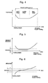
- the heart rate of the subject 10 during breath holding period transits in general as shown in Fig. 4. More specifically, at the beginning of the breath holding period the heart rate tends to decrease, at the middle of the period the heart rate is stable, and at the end of the period the heart rate tends to increase.
- Fig. 5 shows diagrammatically the heart rate transition when indicating the transition of the heart rate in a standard deviation graph
- the standard deviation used here is the deviation of a plurality of heartbeats immediately adjoining. The combination of adjoining heartbeats is movingly altered. Using the standard deviation the stability of the heart rate can be precisely disclosed.
- the stability of the heart rate may be indicated by the differential between heartbeats, instead of the standard deviation.
- the differential is a difference between the maximum heart rate and the minimum heart rate in successive adjoining plural heartbeats.
- the combination of successive adjoining plural heartbeats is movingly altered for each heartbeat.
- Fig. 6 for example is yielded, which indicates the stability of the heart rate by the decrease of differential.
- Using the differential facilitates to indicate the stability of the heart rate.
- the timing of imaging is controlled so as to start imaging when the heart rate is stably settled.
- the control is performed in the operator console 300.
- Fig. 7 shows diagrammatically a schematic flow diagram of the operation of an exemplary embodiment in accordance with the present invention.
- the heart rate is computed.
- the computation of the heart rate is based on the electrocardiogram signals. More specifically, the reciprocal is solved from the period of electrocardiogram signals and is multiplied by 60 to yield the beat per minute (bpm).
- step 403 the stability of the heart rate is computed.
- the index of stability of the heart rate the standard deviation for example is computed.
- the differential between heartbeats may be computed instead of or in addition to the standard deviation.
- step 407 it is determined whether or not the stability of the heart rate is within the tolerance range.
- the tolerance of the heart rate stability is predefined.
- the upper limit of the tolerance in the standard deviation may be defined as 1 or 2.
- the upper and lower limit of the tolerance in the differential may be ⁇ 1. If the heart rate stability is not within the tolerance, the process will proceed back to step 401. While the heart rate stability is not fallen within the tolerance, the system will iteratively repeat the operation of steps 401 to 407.
- the imaging is conducted in step 411. More specifically, the operator console 300 issues an imaging instruction to the gantry 100, which, in response to the instruction, images the subject 10. Since the X-ray detector 150 is a multi-column X-ray detector which may obtain the data for a plurality of slices at once, the heart may be entirely scanned while the heart rate is being stably settled. In this manner, images of better quality can be obtained without being affected by the fluctuation of heart rate at the beginning of breath holding period.
- Fig. 8 shows diagrammatically a schematic flow diagram of the operation of another embodiment of the apparatus in accordance with the present invention.
- the heart rate is computed, then the stability of the heart rate is computed in step 403.
- the standard deviation and/or differential as the indices of the heart rate stability are computed.
- step 407 it is determined whether or not the heart rate stability is fallen within the tolerance. If the heart rate stability is not within the tolerance then the process proceeds back to step 401. While the heart rate stability is not fallen within the tolerance, the process will iteratively repeat the operation of steps 401 to 407.
- an imaging button is lit.
- the imaging button is an illuminated operable button provided on the operator console 300. The operator is informed that the imaging is enabled when the imaging button is lit.
- Fig. 9 shows diagrammatically a schematic flow diagram of the operation of another exemplary apparatus in accordance with the present invention.
- the heart rate is computed, and the heart rate stability is computed in step 403.
- the standard deviation and/or differential as the indices of the heart rate stability are computed.
- step 405 the computation result of the heart rate stability is displayed.
- the result is displayed on the display 302.
- the contents of the display includes the transition of the standard deviation or differential values, a graph as shown in Fig. 5 or Fig. 6 is displayed along with the elapsed time. At this point the tolerance of the stability is also displayed.
- the item displayed on the display 302 may be altematively a graph indicative of the transition of the heart rate as shown in Fig. 4.
- the heart rate stability can also be recognized from this graph. In addition, by storing this graph in the memory, it can be used for the verification after the imaging.
- step 407 it is determined whether or not the heart rate stability is fallen within the tolerance range. The determination may be conducted by the operator monitoring the display 302. While the heart rate stability is not within the tolerance, the system will iteratively repeat the operation of steps 401 to 407.
- the operator pushes the imaging button when he/she decides that the heart rate stability is well within the tolerance. Responsively the imaging will be conducted in step 411. In this manner, images of better quality can be obtained without being affected by the fluctuation of heart rate at the beginning of breath holding period.
- the transition of the heart rate during the breath holding period may vary dependent on a personal error, it is preferable to recognize in advance the way of individual transition by conducting a dry rehearsal with the subject of breath holding to determine the standard deviation and the differential, in order to effectively run the imaging.
Landscapes
- Health & Medical Sciences (AREA)
- Life Sciences & Earth Sciences (AREA)
- Engineering & Computer Science (AREA)
- Medical Informatics (AREA)
- Radiology & Medical Imaging (AREA)
- Molecular Biology (AREA)
- Biophysics (AREA)
- Nuclear Medicine, Radiotherapy & Molecular Imaging (AREA)
- Optics & Photonics (AREA)
- Pathology (AREA)
- Physics & Mathematics (AREA)
- Biomedical Technology (AREA)
- Heart & Thoracic Surgery (AREA)
- High Energy & Nuclear Physics (AREA)
- Surgery (AREA)
- Animal Behavior & Ethology (AREA)
- General Health & Medical Sciences (AREA)
- Public Health (AREA)
- Veterinary Medicine (AREA)
- Pulmonology (AREA)
- Theoretical Computer Science (AREA)
- Physiology (AREA)
- Apparatus For Radiation Diagnosis (AREA)
Applications Claiming Priority (1)
| Application Number | Priority Date | Filing Date | Title |
|---|---|---|---|
| JP2005168221A JP2006340838A (ja) | 2005-06-08 | 2005-06-08 | 撮影制御方法およびx線ct装置 |
Publications (2)
| Publication Number | Publication Date |
|---|---|
| EP1733682A2 true EP1733682A2 (de) | 2006-12-20 |
| EP1733682A3 EP1733682A3 (de) | 2007-02-28 |
Family
ID=37307295
Family Applications (1)
| Application Number | Title | Priority Date | Filing Date |
|---|---|---|---|
| EP06252921A Withdrawn EP1733682A3 (de) | 2005-06-08 | 2006-06-06 | Bildaufnahmesteuerung für eine Röntgen-CT-Vorrichtung |
Country Status (5)
| Country | Link |
|---|---|
| US (1) | US20060280284A1 (de) |
| EP (1) | EP1733682A3 (de) |
| JP (1) | JP2006340838A (de) |
| KR (1) | KR20060128707A (de) |
| CN (1) | CN1973770A (de) |
Families Citing this family (8)
| Publication number | Priority date | Publication date | Assignee | Title |
|---|---|---|---|---|
| JP5773575B2 (ja) * | 2010-03-31 | 2015-09-02 | 株式会社東芝 | X線コンピュータ断層撮影装置 |
| WO2011158136A1 (en) * | 2010-06-17 | 2011-12-22 | Koninklijke Philips Electronics N.V. | Automated heart rate detection for 3d ultrasonic fetal imaging |
| JP5920786B2 (ja) * | 2010-08-31 | 2016-05-18 | 株式会社日立メディコ | 超音波診断装置と心機能検査区間の検索表示方法 |
| JP5762121B2 (ja) * | 2011-05-11 | 2015-08-12 | 株式会社日立メディコ | X線ct装置 |
| KR101351095B1 (ko) | 2011-07-19 | 2014-01-15 | 삼성전자주식회사 | 다중 에너지 엑스선 영상 장치 및 그 제어 방법 |
| CN104337520B (zh) * | 2013-07-30 | 2016-09-07 | 陈德路 | 患者呼吸状态和体位精确记录检测方法 |
| KR102205353B1 (ko) | 2013-09-26 | 2021-01-20 | 삼성전자주식회사 | 엑스선 촬영 장치 및 그 제어 방법 |
| JP7151125B2 (ja) * | 2018-03-29 | 2022-10-12 | コニカミノルタ株式会社 | 撮影支援装置、放射線撮影システム及びプログラム |
Citations (1)
| Publication number | Priority date | Publication date | Assignee | Title |
|---|---|---|---|---|
| JP2004275440A (ja) | 2003-03-14 | 2004-10-07 | Toshiba Corp | X線コンピュータ断層撮影装置 |
Family Cites Families (11)
| Publication number | Priority date | Publication date | Assignee | Title |
|---|---|---|---|---|
| US4547892A (en) * | 1977-04-01 | 1985-10-15 | Technicare Corporation | Cardiac imaging with CT scanner |
| CA1101936A (en) * | 1977-04-01 | 1981-05-26 | Robert H. Wake | Cardiac imaging with ct scanner |
| US5594772A (en) * | 1993-11-26 | 1997-01-14 | Kabushiki Kaisha Toshiba | Computer tomography apparatus |
| US6275560B1 (en) * | 1998-12-22 | 2001-08-14 | General Electric Company | Cardiac gated computed tomography system |
| US6708052B1 (en) * | 2001-04-11 | 2004-03-16 | Harbor Ucla Research And Education Institute | Method and apparatus for cardiac imaging with minimized cardiac motion artifact |
| US6438196B1 (en) * | 2001-06-28 | 2002-08-20 | General Electric Company | EKG driven CT image reconstruction for cardiac imaging |
| US7006862B2 (en) * | 2001-07-17 | 2006-02-28 | Accuimage Diagnostics Corp. | Graphical user interfaces and methods for retrospectively gating a set of images |
| US7020511B2 (en) * | 2002-02-22 | 2006-03-28 | Ge Medical Systems Global Technology Company, Llc | Method for three dimensional cine EBA/CTA imaging |
| US6763082B2 (en) * | 2002-02-27 | 2004-07-13 | Kabushiki Kaisha Toshiba | X-ray computer tomography apparatus |
| US20040077941A1 (en) * | 2002-10-21 | 2004-04-22 | Ge Medical Systems Global Technology Company, Llc | Method and system for image improvement with ECG gating and dose reduction in CT imaging |
| US6865250B2 (en) * | 2002-12-23 | 2005-03-08 | Ge Medical Systems Global Technology Company Llc | High pitch cardiac helical scan with extended reconstruction windows |
-
2005
- 2005-06-08 JP JP2005168221A patent/JP2006340838A/ja active Pending
-
2006
- 2006-05-22 US US11/438,737 patent/US20060280284A1/en not_active Abandoned
- 2006-06-06 EP EP06252921A patent/EP1733682A3/de not_active Withdrawn
- 2006-06-08 KR KR1020060051501A patent/KR20060128707A/ko not_active Ceased
- 2006-06-08 CN CNA2006101718397A patent/CN1973770A/zh active Pending
Patent Citations (1)
| Publication number | Priority date | Publication date | Assignee | Title |
|---|---|---|---|---|
| JP2004275440A (ja) | 2003-03-14 | 2004-10-07 | Toshiba Corp | X線コンピュータ断層撮影装置 |
Also Published As
| Publication number | Publication date |
|---|---|
| CN1973770A (zh) | 2007-06-06 |
| EP1733682A3 (de) | 2007-02-28 |
| KR20060128707A (ko) | 2006-12-14 |
| US20060280284A1 (en) | 2006-12-14 |
| JP2006340838A (ja) | 2006-12-21 |
Similar Documents
| Publication | Publication Date | Title |
|---|---|---|
| EP2238906B1 (de) | Röntgenstrahlen-Computer-Tomographie Gerät | |
| US8379792B2 (en) | X-ray CT apparatus | |
| JP6233980B2 (ja) | X線ct装置及び画像再構成方法 | |
| JP4945203B2 (ja) | X線コンピュータ断層撮影装置 | |
| EP1512375A1 (de) | Verfahren und Gerät zum Ermitteln eines Computertomographiebildgebungsprotokolls | |
| US20080049890A1 (en) | Step-and-shoot cardiac ct imaging | |
| JP4130088B2 (ja) | Ct投影データを用いて運動ゲ−ティングするための方法及び装置 | |
| CN1973771B (zh) | X-射线计算机断层扫描设备和控制该设备的方法 | |
| CN101711682A (zh) | X射线ct装置以及x射线ct装置的控制方法 | |
| JP4175875B2 (ja) | 信号獲得装置およびx線ct装置 | |
| CN100518652C (zh) | X射线计算机断层摄影装置 | |
| EP1733682A2 (de) | Bildaufnahmesteuerung für eine Röntgen-CT-Vorrichtung | |
| JP2001061835A (ja) | マルチスライス型スキャナのシネ・スキャンによる遡及的心同期法 | |
| JP2015058227A (ja) | 医用画像診断装置 | |
| JP4464161B2 (ja) | 放射線画像撮影制御装置及びその制御方法及びプログラム | |
| JP5762121B2 (ja) | X線ct装置 | |
| JP4679951B2 (ja) | X線ct装置 | |
| CN103222877B (zh) | X射线ct装置 | |
| JP2003126081A (ja) | Ct装置 | |
| JP2009207686A (ja) | 心電同期スキャン方法及びx線コンピュータ断層撮影装置 | |
| JP2005125084A (ja) | 放射線撮像装置及び撮像方法 |
Legal Events
| Date | Code | Title | Description |
|---|---|---|---|
| PUAI | Public reference made under article 153(3) epc to a published international application that has entered the european phase |
Free format text: ORIGINAL CODE: 0009012 |
|
| AK | Designated contracting states |
Kind code of ref document: A2 Designated state(s): AT BE BG CH CY CZ DE DK EE ES FI FR GB GR HU IE IS IT LI LT LU LV MC NL PL PT RO SE SI SK TR |
|
| AX | Request for extension of the european patent |
Extension state: AL BA HR MK YU |
|
| PUAL | Search report despatched |
Free format text: ORIGINAL CODE: 0009013 |
|
| AK | Designated contracting states |
Kind code of ref document: A3 Designated state(s): AT BE BG CH CY CZ DE DK EE ES FI FR GB GR HU IE IS IT LI LT LU LV MC NL PL PT RO SE SI SK TR |
|
| AX | Request for extension of the european patent |
Extension state: AL BA HR MK YU |
|
| 17P | Request for examination filed |
Effective date: 20070828 |
|
| 17Q | First examination report despatched |
Effective date: 20071001 |
|
| AKX | Designation fees paid |
Designated state(s): DE FR GB |
|
| STAA | Information on the status of an ep patent application or granted ep patent |
Free format text: STATUS: THE APPLICATION IS DEEMED TO BE WITHDRAWN |
|
| 18D | Application deemed to be withdrawn |
Effective date: 20091231 |