EP1732991B1 - Method of delaminating aggregated particles with a coating agent in a supercritical fluid - Google Patents
Method of delaminating aggregated particles with a coating agent in a supercritical fluid Download PDFInfo
- Publication number
- EP1732991B1 EP1732991B1 EP05760868A EP05760868A EP1732991B1 EP 1732991 B1 EP1732991 B1 EP 1732991B1 EP 05760868 A EP05760868 A EP 05760868A EP 05760868 A EP05760868 A EP 05760868A EP 1732991 B1 EP1732991 B1 EP 1732991B1
- Authority
- EP
- European Patent Office
- Prior art keywords
- particles
- coating agent
- supercritical fluid
- polymer
- delaminated
- Prior art date
- Legal status (The legal status is an assumption and is not a legal conclusion. Google has not performed a legal analysis and makes no representation as to the accuracy of the status listed.)
- Expired - Lifetime
Links
- 239000002245 particle Substances 0.000 title claims abstract description 139
- 239000012530 fluid Substances 0.000 title claims abstract description 83
- 239000011248 coating agent Substances 0.000 title claims abstract description 61
- 238000000034 method Methods 0.000 title claims abstract description 42
- BPQQTUXANYXVAA-UHFFFAOYSA-N Orthosilicate Chemical group [O-][Si]([O-])([O-])[O-] BPQQTUXANYXVAA-UHFFFAOYSA-N 0.000 claims abstract description 18
- 239000002064 nanoplatelet Chemical group 0.000 claims abstract description 18
- 239000002121 nanofiber Chemical group 0.000 claims abstract description 15
- 239000002071 nanotube Chemical group 0.000 claims abstract description 15
- 229920000642 polymer Polymers 0.000 claims description 73
- CURLTUGMZLYLDI-UHFFFAOYSA-N Carbon dioxide Chemical compound O=C=O CURLTUGMZLYLDI-UHFFFAOYSA-N 0.000 claims description 38
- 239000001569 carbon dioxide Substances 0.000 claims description 19
- 229910002092 carbon dioxide Inorganic materials 0.000 claims description 19
- 239000002114 nanocomposite Substances 0.000 claims description 19
- -1 ethylene propylene, propane Chemical class 0.000 claims description 12
- UHOVQNZJYSORNB-UHFFFAOYSA-N Benzene Chemical compound C1=CC=CC=C1 UHOVQNZJYSORNB-UHFFFAOYSA-N 0.000 claims description 6
- OKKJLVBELUTLKV-UHFFFAOYSA-N Methanol Chemical compound OC OKKJLVBELUTLKV-UHFFFAOYSA-N 0.000 claims description 6
- 238000013329 compounding Methods 0.000 claims description 6
- 238000002156 mixing Methods 0.000 claims description 6
- 239000000203 mixture Substances 0.000 claims description 5
- QGZKDVFQNNGYKY-UHFFFAOYSA-N Ammonia Chemical compound N QGZKDVFQNNGYKY-UHFFFAOYSA-N 0.000 claims description 4
- XKRFYHLGVUSROY-UHFFFAOYSA-N Argon Chemical compound [Ar] XKRFYHLGVUSROY-UHFFFAOYSA-N 0.000 claims description 4
- IJGRMHOSHXDMSA-UHFFFAOYSA-N Atomic nitrogen Chemical compound N#N IJGRMHOSHXDMSA-UHFFFAOYSA-N 0.000 claims description 4
- LFQSCWFLJHTTHZ-UHFFFAOYSA-N Ethanol Chemical compound CCO LFQSCWFLJHTTHZ-UHFFFAOYSA-N 0.000 claims description 4
- XPDWGBQVDMORPB-UHFFFAOYSA-N Fluoroform Chemical compound FC(F)F XPDWGBQVDMORPB-UHFFFAOYSA-N 0.000 claims description 4
- GQPLMRYTRLFLPF-UHFFFAOYSA-N Nitrous Oxide Chemical compound [O-][N+]#N GQPLMRYTRLFLPF-UHFFFAOYSA-N 0.000 claims description 4
- OFBQJSOFQDEBGM-UHFFFAOYSA-N Pentane Chemical compound CCCCC OFBQJSOFQDEBGM-UHFFFAOYSA-N 0.000 claims description 4
- JUJWROOIHBZHMG-UHFFFAOYSA-N Pyridine Chemical compound C1=CC=NC=C1 JUJWROOIHBZHMG-UHFFFAOYSA-N 0.000 claims description 4
- VNWKTOKETHGBQD-UHFFFAOYSA-N methane Chemical compound C VNWKTOKETHGBQD-UHFFFAOYSA-N 0.000 claims description 4
- 239000000835 fiber Substances 0.000 claims description 3
- 239000000178 monomer Substances 0.000 claims description 3
- 239000000843 powder Substances 0.000 claims description 3
- 238000009987 spinning Methods 0.000 claims description 3
- XLYOFNOQVPJJNP-UHFFFAOYSA-N water Substances O XLYOFNOQVPJJNP-UHFFFAOYSA-N 0.000 claims description 3
- OTMSDBZUPAUEDD-UHFFFAOYSA-N Ethane Chemical compound CC OTMSDBZUPAUEDD-UHFFFAOYSA-N 0.000 claims description 2
- NINIDFKCEFEMDL-UHFFFAOYSA-N Sulfur Chemical compound [S] NINIDFKCEFEMDL-UHFFFAOYSA-N 0.000 claims description 2
- 125000005233 alkylalcohol group Chemical group 0.000 claims description 2
- 229910021529 ammonia Inorganic materials 0.000 claims description 2
- 229910052786 argon Inorganic materials 0.000 claims description 2
- 238000005266 casting Methods 0.000 claims description 2
- AFYPFACVUDMOHA-UHFFFAOYSA-N chlorotrifluoromethane Chemical compound FC(F)(F)Cl AFYPFACVUDMOHA-UHFFFAOYSA-N 0.000 claims description 2
- 230000005684 electric field Effects 0.000 claims description 2
- 235000019441 ethanol Nutrition 0.000 claims description 2
- WMIYKQLTONQJES-UHFFFAOYSA-N hexafluoroethane Chemical compound FC(F)(F)C(F)(F)F WMIYKQLTONQJES-UHFFFAOYSA-N 0.000 claims description 2
- 238000000465 moulding Methods 0.000 claims description 2
- 229910052757 nitrogen Inorganic materials 0.000 claims description 2
- 239000001272 nitrous oxide Substances 0.000 claims description 2
- UMJSCPRVCHMLSP-UHFFFAOYSA-N pyridine Natural products COC1=CC=CN=C1 UMJSCPRVCHMLSP-UHFFFAOYSA-N 0.000 claims description 2
- 229910052717 sulfur Inorganic materials 0.000 claims description 2
- 239000011593 sulfur Substances 0.000 claims description 2
- 229920000435 poly(dimethylsiloxane) Polymers 0.000 description 24
- 239000004205 dimethyl polysiloxane Substances 0.000 description 23
- 235000013870 dimethyl polysiloxane Nutrition 0.000 description 23
- CXQXSVUQTKDNFP-UHFFFAOYSA-N octamethyltrisiloxane Chemical compound C[Si](C)(C)O[Si](C)(C)O[Si](C)(C)C CXQXSVUQTKDNFP-UHFFFAOYSA-N 0.000 description 23
- 238000004987 plasma desorption mass spectroscopy Methods 0.000 description 23
- 239000004927 clay Substances 0.000 description 22
- 238000002441 X-ray diffraction Methods 0.000 description 14
- 230000008569 process Effects 0.000 description 10
- 230000001965 increasing effect Effects 0.000 description 9
- 239000000463 material Substances 0.000 description 9
- 230000004888 barrier function Effects 0.000 description 7
- 239000007788 liquid Substances 0.000 description 7
- 150000004760 silicates Chemical class 0.000 description 7
- 239000007789 gas Substances 0.000 description 6
- 238000010438 heat treatment Methods 0.000 description 6
- 239000010410 layer Substances 0.000 description 6
- 229910052901 montmorillonite Inorganic materials 0.000 description 6
- 239000000126 substance Substances 0.000 description 5
- 238000005341 cation exchange Methods 0.000 description 4
- 238000004519 manufacturing process Methods 0.000 description 4
- 239000002244 precipitate Substances 0.000 description 4
- 206010040844 Skin exfoliation Diseases 0.000 description 3
- 238000004299 exfoliation Methods 0.000 description 3
- 239000011521 glass Substances 0.000 description 3
- 230000006872 improvement Effects 0.000 description 3
- 229920000139 polyethylene terephthalate Polymers 0.000 description 3
- 239000005020 polyethylene terephthalate Substances 0.000 description 3
- 238000006116 polymerization reaction Methods 0.000 description 3
- 239000000047 product Substances 0.000 description 3
- 150000001767 cationic compounds Chemical class 0.000 description 2
- 239000002131 composite material Substances 0.000 description 2
- 150000001875 compounds Chemical class 0.000 description 2
- 230000003750 conditioning effect Effects 0.000 description 2
- GUJOJGAPFQRJSV-UHFFFAOYSA-N dialuminum;dioxosilane;oxygen(2-);hydrate Chemical compound O.[O-2].[O-2].[O-2].[Al+3].[Al+3].O=[Si]=O.O=[Si]=O.O=[Si]=O.O=[Si]=O GUJOJGAPFQRJSV-UHFFFAOYSA-N 0.000 description 2
- 238000009792 diffusion process Methods 0.000 description 2
- 239000000945 filler Substances 0.000 description 2
- 229920001903 high density polyethylene Polymers 0.000 description 2
- 239000004700 high-density polyethylene Substances 0.000 description 2
- 238000001746 injection moulding Methods 0.000 description 2
- 229910001411 inorganic cation Inorganic materials 0.000 description 2
- 238000009830 intercalation Methods 0.000 description 2
- 230000002687 intercalation Effects 0.000 description 2
- 239000011229 interlayer Substances 0.000 description 2
- 229920001684 low density polyethylene Polymers 0.000 description 2
- 239000004702 low-density polyethylene Substances 0.000 description 2
- 239000012528 membrane Substances 0.000 description 2
- 150000002892 organic cations Chemical class 0.000 description 2
- 229920003023 plastic Polymers 0.000 description 2
- 239000004033 plastic Substances 0.000 description 2
- 229920003229 poly(methyl methacrylate) Polymers 0.000 description 2
- 230000002787 reinforcement Effects 0.000 description 2
- 230000003381 solubilizing effect Effects 0.000 description 2
- 230000008961 swelling Effects 0.000 description 2
- AYCANDRGVPTASA-UHFFFAOYSA-N 1-bromo-1,2,2-trifluoroethene Chemical group FC(F)=C(F)Br AYCANDRGVPTASA-UHFFFAOYSA-N 0.000 description 1
- 239000004801 Chlorinated PVC Substances 0.000 description 1
- LCGLNKUTAGEVQW-UHFFFAOYSA-N Dimethyl ether Chemical compound COC LCGLNKUTAGEVQW-UHFFFAOYSA-N 0.000 description 1
- 229920000877 Melamine resin Polymers 0.000 description 1
- 239000006057 Non-nutritive feed additive Substances 0.000 description 1
- 239000004677 Nylon Substances 0.000 description 1
- 239000004952 Polyamide Substances 0.000 description 1
- 239000004698 Polyethylene Substances 0.000 description 1
- 239000004721 Polyphenylene oxide Substances 0.000 description 1
- 239000004743 Polypropylene Substances 0.000 description 1
- 239000004793 Polystyrene Substances 0.000 description 1
- 229910000831 Steel Inorganic materials 0.000 description 1
- 229920001807 Urea-formaldehyde Polymers 0.000 description 1
- 150000001241 acetals Chemical class 0.000 description 1
- 229920002877 acrylic styrene acrylonitrile Polymers 0.000 description 1
- 229920006397 acrylic thermoplastic Polymers 0.000 description 1
- XECAHXYUAAWDEL-UHFFFAOYSA-N acrylonitrile butadiene styrene Chemical compound C=CC=C.C=CC#N.C=CC1=CC=CC=C1 XECAHXYUAAWDEL-UHFFFAOYSA-N 0.000 description 1
- 239000004676 acrylonitrile butadiene styrene Substances 0.000 description 1
- 229920000122 acrylonitrile butadiene styrene Polymers 0.000 description 1
- 125000005210 alkyl ammonium group Chemical group 0.000 description 1
- AZDRQVAHHNSJOQ-UHFFFAOYSA-N alumane Chemical group [AlH3] AZDRQVAHHNSJOQ-UHFFFAOYSA-N 0.000 description 1
- 229920003180 amino resin Polymers 0.000 description 1
- 239000007864 aqueous solution Substances 0.000 description 1
- 230000015572 biosynthetic process Effects 0.000 description 1
- DQXBYHZEEUGOBF-UHFFFAOYSA-N but-3-enoic acid;ethene Chemical compound C=C.OC(=O)CC=C DQXBYHZEEUGOBF-UHFFFAOYSA-N 0.000 description 1
- 239000003054 catalyst Substances 0.000 description 1
- 230000008859 change Effects 0.000 description 1
- 229920000457 chlorinated polyvinyl chloride Polymers 0.000 description 1
- UUAGAQFQZIEFAH-UHFFFAOYSA-N chlorotrifluoroethylene Chemical group FC(F)=C(F)Cl UUAGAQFQZIEFAH-UHFFFAOYSA-N 0.000 description 1
- 238000000576 coating method Methods 0.000 description 1
- 238000004891 communication Methods 0.000 description 1
- 230000003247 decreasing effect Effects 0.000 description 1
- 230000032798 delamination Effects 0.000 description 1
- 238000010586 diagram Methods 0.000 description 1
- 238000005516 engineering process Methods 0.000 description 1
- 230000002708 enhancing effect Effects 0.000 description 1
- 239000003822 epoxy resin Substances 0.000 description 1
- 239000005038 ethylene vinyl acetate Substances 0.000 description 1
- 230000002349 favourable effect Effects 0.000 description 1
- SLGWESQGEUXWJQ-UHFFFAOYSA-N formaldehyde;phenol Chemical compound O=C.OC1=CC=CC=C1 SLGWESQGEUXWJQ-UHFFFAOYSA-N 0.000 description 1
- 238000005194 fractionation Methods 0.000 description 1
- 239000000446 fuel Substances 0.000 description 1
- 239000002828 fuel tank Substances 0.000 description 1
- 239000003365 glass fiber Substances 0.000 description 1
- 230000005484 gravity Effects 0.000 description 1
- LNEPOXFFQSENCJ-UHFFFAOYSA-N haloperidol Chemical compound C1CC(O)(C=2C=CC(Cl)=CC=2)CCN1CCCC(=O)C1=CC=C(F)C=C1 LNEPOXFFQSENCJ-UHFFFAOYSA-N 0.000 description 1
- 230000002209 hydrophobic effect Effects 0.000 description 1
- 230000003993 interaction Effects 0.000 description 1
- 238000005342 ion exchange Methods 0.000 description 1
- JEIPFZHSYJVQDO-UHFFFAOYSA-N iron(III) oxide Inorganic materials O=[Fe]O[Fe]=O JEIPFZHSYJVQDO-UHFFFAOYSA-N 0.000 description 1
- 238000011068 loading method Methods 0.000 description 1
- 229920002521 macromolecule Polymers 0.000 description 1
- 239000011159 matrix material Substances 0.000 description 1
- 230000007246 mechanism Effects 0.000 description 1
- JDSHMPZPIAZGSV-UHFFFAOYSA-N melamine Chemical compound NC1=NC(N)=NC(N)=N1 JDSHMPZPIAZGSV-UHFFFAOYSA-N 0.000 description 1
- 239000000155 melt Substances 0.000 description 1
- 239000002105 nanoparticle Substances 0.000 description 1
- 229920001778 nylon Polymers 0.000 description 1
- 239000003921 oil Substances 0.000 description 1
- 230000000149 penetrating effect Effects 0.000 description 1
- ISWSIDIOOBJBQZ-UHFFFAOYSA-N phenol group Chemical group C1(=CC=CC=C1)O ISWSIDIOOBJBQZ-UHFFFAOYSA-N 0.000 description 1
- 229920001568 phenolic resin Polymers 0.000 description 1
- 229920003199 poly(diethylsiloxane) Polymers 0.000 description 1
- 229920001200 poly(ethylene-vinyl acetate) Polymers 0.000 description 1
- 229920002432 poly(vinyl methyl ether) polymer Polymers 0.000 description 1
- 229920001921 poly-methyl-phenyl-siloxane Polymers 0.000 description 1
- 229920002647 polyamide Polymers 0.000 description 1
- 229920001748 polybutylene Polymers 0.000 description 1
- 229920001707 polybutylene terephthalate Polymers 0.000 description 1
- 239000004417 polycarbonate Substances 0.000 description 1
- 229920000515 polycarbonate Polymers 0.000 description 1
- 229920000647 polyepoxide Polymers 0.000 description 1
- 229920000728 polyester Polymers 0.000 description 1
- 229920000570 polyether Polymers 0.000 description 1
- 229920000573 polyethylene Polymers 0.000 description 1
- 239000002952 polymeric resin Substances 0.000 description 1
- 239000004926 polymethyl methacrylate Substances 0.000 description 1
- ODGAOXROABLFNM-UHFFFAOYSA-N polynoxylin Chemical compound O=C.NC(N)=O ODGAOXROABLFNM-UHFFFAOYSA-N 0.000 description 1
- 229920000098 polyolefin Polymers 0.000 description 1
- 229920006380 polyphenylene oxide Polymers 0.000 description 1
- 229920001155 polypropylene Polymers 0.000 description 1
- 229920002223 polystyrene Polymers 0.000 description 1
- 229920001343 polytetrafluoroethylene Polymers 0.000 description 1
- 229920002635 polyurethane Polymers 0.000 description 1
- 239000004814 polyurethane Substances 0.000 description 1
- 239000004800 polyvinyl chloride Substances 0.000 description 1
- 238000000746 purification Methods 0.000 description 1
- 230000003014 reinforcing effect Effects 0.000 description 1
- 238000009877 rendering Methods 0.000 description 1
- 230000008521 reorganization Effects 0.000 description 1
- 229920005989 resin Polymers 0.000 description 1
- 239000011347 resin Substances 0.000 description 1
- 230000003678 scratch resistant effect Effects 0.000 description 1
- 239000000565 sealant Substances 0.000 description 1
- 238000000926 separation method Methods 0.000 description 1
- 238000007493 shaping process Methods 0.000 description 1
- 239000000243 solution Substances 0.000 description 1
- 239000002904 solvent Substances 0.000 description 1
- 238000000807 solvent casting Methods 0.000 description 1
- 239000010959 steel Substances 0.000 description 1
- 229920003002 synthetic resin Polymers 0.000 description 1
- ISXSCDLOGDJUNJ-UHFFFAOYSA-N tert-butyl prop-2-enoate Chemical compound CC(C)(C)OC(=O)C=C ISXSCDLOGDJUNJ-UHFFFAOYSA-N 0.000 description 1
- 229920001169 thermoplastic Polymers 0.000 description 1
- 229920005992 thermoplastic resin Polymers 0.000 description 1
- 229920001187 thermosetting polymer Polymers 0.000 description 1
- 239000004416 thermosoftening plastic Substances 0.000 description 1
- 230000003313 weakening effect Effects 0.000 description 1
Images

Classifications
-
- C—CHEMISTRY; METALLURGY
- C09—DYES; PAINTS; POLISHES; NATURAL RESINS; ADHESIVES; COMPOSITIONS NOT OTHERWISE PROVIDED FOR; APPLICATIONS OF MATERIALS NOT OTHERWISE PROVIDED FOR
- C09C—TREATMENT OF INORGANIC MATERIALS, OTHER THAN FIBROUS FILLERS, TO ENHANCE THEIR PIGMENTING OR FILLING PROPERTIES ; PREPARATION OF CARBON BLACK ; PREPARATION OF INORGANIC MATERIALS WHICH ARE NO SINGLE CHEMICAL COMPOUNDS AND WHICH ARE MAINLY USED AS PIGMENTS OR FILLERS
- C09C3/00—Treatment in general of inorganic materials, other than fibrous fillers, to enhance their pigmenting or filling properties
- C09C3/12—Treatment with organosilicon compounds
-
- B—PERFORMING OPERATIONS; TRANSPORTING
- B82—NANOTECHNOLOGY
- B82Y—SPECIFIC USES OR APPLICATIONS OF NANOSTRUCTURES; MEASUREMENT OR ANALYSIS OF NANOSTRUCTURES; MANUFACTURE OR TREATMENT OF NANOSTRUCTURES
- B82Y30/00—Nanotechnology for materials or surface science, e.g. nanocomposites
-
- C—CHEMISTRY; METALLURGY
- C09—DYES; PAINTS; POLISHES; NATURAL RESINS; ADHESIVES; COMPOSITIONS NOT OTHERWISE PROVIDED FOR; APPLICATIONS OF MATERIALS NOT OTHERWISE PROVIDED FOR
- C09C—TREATMENT OF INORGANIC MATERIALS, OTHER THAN FIBROUS FILLERS, TO ENHANCE THEIR PIGMENTING OR FILLING PROPERTIES ; PREPARATION OF CARBON BLACK ; PREPARATION OF INORGANIC MATERIALS WHICH ARE NO SINGLE CHEMICAL COMPOUNDS AND WHICH ARE MAINLY USED AS PIGMENTS OR FILLERS
- C09C1/00—Treatment of specific inorganic materials other than fibrous fillers; Preparation of carbon black
- C09C1/28—Compounds of silicon
-
- C—CHEMISTRY; METALLURGY
- C09—DYES; PAINTS; POLISHES; NATURAL RESINS; ADHESIVES; COMPOSITIONS NOT OTHERWISE PROVIDED FOR; APPLICATIONS OF MATERIALS NOT OTHERWISE PROVIDED FOR
- C09C—TREATMENT OF INORGANIC MATERIALS, OTHER THAN FIBROUS FILLERS, TO ENHANCE THEIR PIGMENTING OR FILLING PROPERTIES ; PREPARATION OF CARBON BLACK ; PREPARATION OF INORGANIC MATERIALS WHICH ARE NO SINGLE CHEMICAL COMPOUNDS AND WHICH ARE MAINLY USED AS PIGMENTS OR FILLERS
- C09C1/00—Treatment of specific inorganic materials other than fibrous fillers; Preparation of carbon black
- C09C1/40—Compounds of aluminium
- C09C1/42—Clays
-
- C—CHEMISTRY; METALLURGY
- C09—DYES; PAINTS; POLISHES; NATURAL RESINS; ADHESIVES; COMPOSITIONS NOT OTHERWISE PROVIDED FOR; APPLICATIONS OF MATERIALS NOT OTHERWISE PROVIDED FOR
- C09C—TREATMENT OF INORGANIC MATERIALS, OTHER THAN FIBROUS FILLERS, TO ENHANCE THEIR PIGMENTING OR FILLING PROPERTIES ; PREPARATION OF CARBON BLACK ; PREPARATION OF INORGANIC MATERIALS WHICH ARE NO SINGLE CHEMICAL COMPOUNDS AND WHICH ARE MAINLY USED AS PIGMENTS OR FILLERS
- C09C3/00—Treatment in general of inorganic materials, other than fibrous fillers, to enhance their pigmenting or filling properties
- C09C3/10—Treatment with macromolecular organic compounds
-
- C—CHEMISTRY; METALLURGY
- C01—INORGANIC CHEMISTRY
- C01P—INDEXING SCHEME RELATING TO STRUCTURAL AND PHYSICAL ASPECTS OF SOLID INORGANIC COMPOUNDS
- C01P2002/00—Crystal-structural characteristics
- C01P2002/70—Crystal-structural characteristics defined by measured X-ray, neutron or electron diffraction data
- C01P2002/72—Crystal-structural characteristics defined by measured X-ray, neutron or electron diffraction data by d-values or two theta-values, e.g. as X-ray diagram
-
- C—CHEMISTRY; METALLURGY
- C01—INORGANIC CHEMISTRY
- C01P—INDEXING SCHEME RELATING TO STRUCTURAL AND PHYSICAL ASPECTS OF SOLID INORGANIC COMPOUNDS
- C01P2004/00—Particle morphology
- C01P2004/10—Particle morphology extending in one dimension, e.g. needle-like
-
- C—CHEMISTRY; METALLURGY
- C01—INORGANIC CHEMISTRY
- C01P—INDEXING SCHEME RELATING TO STRUCTURAL AND PHYSICAL ASPECTS OF SOLID INORGANIC COMPOUNDS
- C01P2004/00—Particle morphology
- C01P2004/10—Particle morphology extending in one dimension, e.g. needle-like
- C01P2004/13—Nanotubes
-
- C—CHEMISTRY; METALLURGY
- C01—INORGANIC CHEMISTRY
- C01P—INDEXING SCHEME RELATING TO STRUCTURAL AND PHYSICAL ASPECTS OF SOLID INORGANIC COMPOUNDS
- C01P2004/00—Particle morphology
- C01P2004/20—Particle morphology extending in two dimensions, e.g. plate-like
-
- C—CHEMISTRY; METALLURGY
- C01—INORGANIC CHEMISTRY
- C01P—INDEXING SCHEME RELATING TO STRUCTURAL AND PHYSICAL ASPECTS OF SOLID INORGANIC COMPOUNDS
- C01P2004/00—Particle morphology
- C01P2004/60—Particles characterised by their size
- C01P2004/61—Micrometer sized, i.e. from 1-100 micrometer
-
- C—CHEMISTRY; METALLURGY
- C01—INORGANIC CHEMISTRY
- C01P—INDEXING SCHEME RELATING TO STRUCTURAL AND PHYSICAL ASPECTS OF SOLID INORGANIC COMPOUNDS
- C01P2004/00—Particle morphology
- C01P2004/60—Particles characterised by their size
- C01P2004/62—Submicrometer sized, i.e. from 0.1-1 micrometer
-
- C—CHEMISTRY; METALLURGY
- C01—INORGANIC CHEMISTRY
- C01P—INDEXING SCHEME RELATING TO STRUCTURAL AND PHYSICAL ASPECTS OF SOLID INORGANIC COMPOUNDS
- C01P2004/00—Particle morphology
- C01P2004/60—Particles characterised by their size
- C01P2004/64—Nanometer sized, i.e. from 1-100 nanometer
-
- Y—GENERAL TAGGING OF NEW TECHNOLOGICAL DEVELOPMENTS; GENERAL TAGGING OF CROSS-SECTIONAL TECHNOLOGIES SPANNING OVER SEVERAL SECTIONS OF THE IPC; TECHNICAL SUBJECTS COVERED BY FORMER USPC CROSS-REFERENCE ART COLLECTIONS [XRACs] AND DIGESTS
- Y02—TECHNOLOGIES OR APPLICATIONS FOR MITIGATION OR ADAPTATION AGAINST CLIMATE CHANGE
- Y02P—CLIMATE CHANGE MITIGATION TECHNOLOGIES IN THE PRODUCTION OR PROCESSING OF GOODS
- Y02P20/00—Technologies relating to chemical industry
- Y02P20/50—Improvements relating to the production of bulk chemicals
- Y02P20/54—Improvements relating to the production of bulk chemicals using solvents, e.g. supercritical solvents or ionic liquids
Definitions
- the present invention relates to a method of delaminating aggregated particles of silicate, nanoplatelet, nanofiber, or nanotube structures.
- the delaminated structures are useful for mixing with a polymer to produce a reinforced polymer having improved properties.
- polymer-based materials may comprise a significant portion, e.g., at least 15 percent, of a given vehicle's weight. These materials are used in various automotive components, such as, interior and exterior trim and side panels. As the industry seeks to improve fuel economy, more steel and aluminum parts may be targeted for replacement by polymer-based materials.
- mechanical properties include stiffness, dimensional stability, modulus, heat deflection temperature, barrier properties, and rust and dent resistance.
- Improved mechanical properties may reduce manufacturing costs by reducing the part thickness and weight of the manufactured part and the manufacturing time thereof.
- nanocomposite there are a number of ways to improve the properties of a polymer, including reinforcement with particulate fillers or glass fibers. It is known that polymers reinforced with nanometer-sized platelets or particles of layered silicates or clay can significantly improve the mechanical properties at much lower loading than conventional fillers. (See U.S. Patent No. 6,469,073 issued to Manke et al. (2002 ).) This type of composite is termed a "nanocomposite.” More specifically, polymer-silicate nanocomposites are compositions in which nano-sized particles of a layered silicate, e.g., montmorillonite clay, are dispersed into a thermoplastic or a thermoset matrix. The improvement in mechanical properties of nanocomposites is believed to be due to factors such as the increased surface area of the particles.
- a layered silicate e.g., montmorillonite clay
- clay In its natural state, clay is made up of stacks of individual particles held together by ionic forces. The spacing between the layers is in the order of about 1 nanometer (nm) which is smaller than the radius of gyration of typical polymers. Consequently, there is a large entropic barrier that inhibits the polymer from penetrating this gap and intermixing with the clay.
- nm nanometer
- Organically treated clays have been achieved by performing intercalation chemistry to exchange a naturally occurring inorganic cation with a bulky organic cation.
- the first step involves a process of conditioning or preparing the clay to make it more compatible with a selected polymer.
- the conditioning step is performed because the clay is generally hydrophilic and many polymer resins of interest are hydrophobic, thus rendering the two relatively incompatible.
- a cation exchange is then performed to exchange a naturally occurring inorganic cation with an organic cation.
- this process may increase the interlayer spacing between each particle, lessening the attractive forces between them. This allows the clay to be compatible with the polymer for subsequent polymerization or compounding.
- cation exchange This preparatory step is known as "cation exchange.”
- cation exchange is performed with a batch reactor containing an aqueous solution wherein an organic molecule, usually an alkyl ammonium salt, is dissolved into water along with the clay particles. The reactor is then heated. Once ion exchange takes place, the clay particles precipitate out and are then dried.
- a monomer may be further intercalated into the clay galleries.
- the organically modified clay is then ready for melt compounding to combine the clay with the polymer to make a workable material.
- Both the polymerization step and the melt compounding step involve known processing conditions in which the particles disperse and exfoliate in the polymer.
- any gaseous compound becomes supercritical when compressed to a pressure higher than its critical pressure (Pc) above its critical temperature (Tc).
- Pc critical pressure
- Tc critical temperature
- the spacing between the layers may increase, may remain the same due to reformation of the weak bonds, or may decrease due to the relaxation and reorganization of organic moieties.
- the present invention generally provides a method of delaminating aggregated particles of natural silicate, nanoplatelet, nanofiber, or nanotube structures with a coating agent solubilized in a substantially supercritical fluid.
- the deliminated particles may be implemented to reinforce materials such as polymers for enhanced mechanical, chemical, barrier and fire retardancy properties of the polymer.
- the method of the invention comprises diffusing a coating agent in a supercritical fluid between the aggregated particles.
- the method further comprises catastrophically depressurizing the substantially supercritical fluid to form delaminated particles.
- the method of the present invention includes a method of preparing a reinforced polymer.
- the method comprises diffusing a coating agent solubilized in a substantially supercritical fluid between aggregated particles of silicate, nanoplatelet, nanofiber, or nanotube structures defining contacted particles.
- the method further comprises catastrophically depressurizing the supercritical fluid to exfoliate the contacted particles and reduce reaggregation of the structures.
- the coating agent is precipitated from the substantially supercritical fluid and deposited on the contacted particles during depressurization defining delaminated particles.
- the method further comprises processing the delaminated particles with a miscible polymer or an immiscible polymer to form delaminated particle-polymer nanocomposites defining the reinforced polymer.
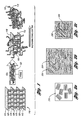
- Figure 1 is a perspective view of a schematic representation of diffusing aggregated particles of natural silicate, nanoplatelet, nanofiber, or nanotube structures by a coating agent solubilized in a supercritical fluid;
- Figure 2a is a cross-sectional view of a conceptual image of aggregated particles of silicate, nanoplatelet, nanofiber, or nanotube structures before processing with a coating agent in a supercritical fluid in accordance with one embodiment of the present invention
- Figure 2b is a cross-sectional view of a conceptual image of the particles when diffused with a coating agent in a supercritical fluid;
- Figure 2c is a cross-sectional view of a conceptual image of the particles after depressurization from supercritical conditions
- Figure 3 is a side view of a system for delaminating aggregated particles of silicate, nanoplatelet, nanofiber, or nanotube structures in accordance with one embodiment of the present invention
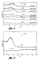
- Figure 5 is a plot of x-ray diffraction patterns of untreated and treated particles of silicate, nanoplatelet, nanofiber, or nanotube structures having different amounts of coating agent;
- Figure 4 is a plot of x-ray diffraction patterns of treated particles with a supercritical fluid having a coating agent at different molecular weights
- Figure 6 is a plot of x-ray diffraction patterns of untreated and treated particles with a coating agent and mixed with an immiscible polymer
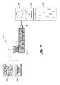
- Figure 7 is a schematic diagram of a process for mixing delaminated particles to prepare reinforced polymers.
- An example of the present invention comprises a method of delaminating aggregated particles with a coating agent solubilized in a substantially supercritical fluid, e.g., a supercritical fluid or a near-critical fluid.
- the method comprises providing aggregated particles and providing the coating agent solubilized in the substantially supercritical fluid.
- the aggregated particles comprise natural layered silicate, layered nanoplatelet, aggregated nanofiber, or aggregated nanotube structures.
- Suitable particles for use in the present invention has one or more of the following properties: layered or aggregated individual particles in powder form having a size between about 2nm and 1 mm, a specific gravity of about 1 to 4, and perpendicular space between the layers of about 2 to 30 angstroms.
- a near critical fluid may have a parameter such as a pressure or a temperature slightly below the pressure or the temperature of its critical condition.
- the critical pressure of carbon dioxide is 73.8 bar and its critical temperature is 301 K.
- carbon dioxide may have a near critical pressure of between about 3.0 bar and 73.7 bar.
- carbon dioxide may have a near critical temperature of between 100K and 300K.
- a fluid at its near critical condition typically experiences properties such as enhanced compressibility and low surface tension to name a few.
- the supercritical fluid of the present invention is preferably a supercritical fluid.
- the supercritical fluid is preferably carbon dioxide which may exist as a fluid having properties of both a liquid and a gas when above its critical temperature and critical pressure. Carbon dioxide at its supercritical conditions has both a gaseous property, being able to penetrate through many materials and a liquid property, being able to dissolve materials into their components.
- the supercritical fluid is preferably carbon dioxide
- the supercritical fluid may comprise other suitable fluids such as methane, ethane, nitrogen, argon, nitrous oxide, alkyl alcohols, ethylene propylene, propane, pentane, benzene, pyridine, water, ethyl alcohol, methyl alcohol, ammonia, sulfur hexaflouride, hexafluoroethane, fluoroform, chlorotrifluoromethane, or mixtures thereof.
- suitable fluids such as methane, ethane, nitrogen, argon, nitrous oxide, alkyl alcohols, ethylene propylene, propane, pentane, benzene, pyridine, water, ethyl alcohol, methyl alcohol, ammonia, sulfur hexaflouride, hexafluoroethane, fluoroform, chlorotrifluoromethane, or mixtures thereof.
- the substantially supercritical fluid is preferably a supercritical fluid.
- a near-critical fluid may be used in lieu of the supercritical fluid which is referred to hereafter.
- a coating agent in accordance with the present invention comprises compounds which can be solubilized in the supercritical fluid to diffuse between the layered silicate, layered nanoplatelet, aggregated nanofiber, or aggregated nanotube structures.
- the coating agent may include polymers, oligomers, monomers, and oils or mixtures thereof soluble in the supercritical fluid.
- the coating agent is poly-(dimethylsiloxane) ("PDMS”) having a weight average molecular weight of preferably between about 500 and 300000.
- Suitable coating agents may be used such as poly- (tetrafluoroethylene-co-hexafluoropropylene), poly-(perfluoropropylene oxide), poly-(diethylsiloxane), poly-(dimethylsilicone), poly-(phenylmethylsilicone), perfluoroalkylpolyethers, chlorotrifluoroethylene, and bromotrifluoroethylene, poly (vinly methyl ether) (PVME), polyethers.
- PVME poly (vinly methyl ether)
- the aggregated particles and the coating agent are preferably placed in a compartment of a high-pressurized vessel isolatable from the atmosphere.
- the aggregated particles comprise about 10 to 90 weight percent and the coating agent comprises about 90 to 10 weight percent of material placed in the vessel.
- the weight ratio of aggregated particles to coating agent is preferably at least about 1 :10. Then, the compartment is sealed off from the atmosphere.
- the compartment may be isolated by any conventional means.
- high-pressurized carbon dioxide is then introduced into the compartment and is pressurized in the vessel to above about 7.24MPa to 70MPa, and preferably to above about 7.58MPa. Then, heat is applied to the vessel to heat the vessel to a temperature above about 35 to 150 degrees Celsius, and preferably to above about 70 degrees Celsius.
- These conditions define a supercritical condition of carbon dioxide whereby the coating agent solubilizes in the supercritical carbon dioxide.
- other ranges may be used for other supercritical fluids. Pressurizing and heating the particles with the supercritical fluid may be accomplished by any conventional means.
- the coating agent When the coating agent solubilizes in the supercritical fluid, the coating agent diffuses between the aggregated particles, defining contacted particles. It is to be understood that the term “diffuses” mentioned above may be equated to "expands” or “swells” with respect to the coating agent and the aggregated particles.
- the vessel is heated by any conventional heating jacket or electrical heating tape disposed about the vessel.
- diffusing the coating agent between the aggregated particles includes maintaining diffusion for between about 10 minutes to 24 hours at supercritical conditions and preferably 3 hours, to produce contacted particles.
- the method further comprises catastrophically depressurizing the contacted particles to precipitate the coating agent from the supercritical fluid and to deposit the coating agent on the contacted particles, defining delaminated particles.
- the supercritical fluid expands which mechanically intercalates the aggregated particles and the coating agent precipitates from the depressurized fluid onto the layers.
- the contacted particles are exfoliated such that the particles are substantially delaminated and disordered, preventing reaggregation of the structures.
- the "intercalation” of the particles is understood to mean when the coating agent or supercritical fluid moves into the gallery spacing between the particles, but causes less than about 20-30A of separation between the particles. Moreover, it is also to be understood that “exfoliation” or “delamination” occurs when the coating agent or supercritical fluid further separates the clay platelets by at least about 8 ⁇ A.
- depressurizing comprises immediately depressurizing the vessel down to a considerably lower pressure, preferably ambient pressure. This may be accomplished in a time period of between about 5 and 30 seconds, and preferably 15 seconds. The pressure decrease may be accomplished by opening the compartment to the atmosphere.
- heating is stopped, thus lowering the temperature of the particles.
- immediate depressurization occurs, the particles are delaminated or substantially singly dispersed apart from each other.
- the low viscosity and high diffusivity of the supercritical fluid allows the coating agent solubilized therein to become disposed or intercalated between the particles during supercritical conditions, providing an increase in interlayer spacing therebetween. It is further believed that, upon depressurization, the supercritical fluid disposed interstitially between the particles force the particles to exfoliate or delaminate from each other, and the coating agent previously solubilized in the supercritical fluid precipitates therefrom to deposit on the contacted particles, preventing reaggregation of the structures. That is, the coating agent precipitates from the supercritical fluid and attaches to each of the delaminated particles. Thus, a substantially uniformly dispersed amount of delaminated particles results.
- the delaminated particles may be prepared for use in several applications.
- the delaminated particles may be mixed or incorporated with a polymer to form a particle-polymer nanocomposite having high surface area contact between the particles and the polymer.
- the particle-polymer nanocomposites may comprise between about 0.1 and 40 weight percent of the particles of silicate, nanoplatelet, nanofiber, or nanotube structures.
- the particles contained in the particle-polymer nanocomposites have a relatively high surface area to weight ratio. The high surface area substantially enhances the polymer by an increase in interfacial interactions while having little added weight. It has been found that polymers reinforced with delaminated particles of silicate, nanoplatelet, nanofiber, or nanotube structures provide substantially increased chemical resistance, heat conductivity, barrier, fire retardancy, and mechanical properties along with lower manufacturing time and cost.
- the polymer may be any suitable polymer, such as the following plastics: polyvinyl chloride (PVC), polyethylene terephthalate, polyacrylonitrite, high density polyethylene (HDPE), polyethylene terephthalate (PETE), polyethylene triphallate (PET), polycarbonate, polyolefins, polypropylene, polystyrene, low density polyethylene (LDPE), polybutylene terephthalate, ethylene-vinyl acetate, acrylic-styrene-acrylonitrile, melamine and urea formaldehyde, polyurethane, acrylonitrile-butadiene-styrene, phenolic, polybutylene, polyester, chlorinated polyvinyl chloride, polyphenylene oxide, epoxy resins, polyacrylics, polymethyl methacrylate, acetals, acrylics, amino resins cellulosics, polyamides, phenol formaldehyde, nylon, or polytetrafluroethylene.
- Particle-polymer nanocomposites such as those described above may be manufactured by disposing the delaminated particles and the polymer using processing.
- the processing may be performed using a conventional mixer, extruder, injection molding machine, fiber spinning, compounding, solvent casting known in the art which has been used to mix finely divided reinforcing particles with polymer to form a particle-polymer nanocomposites.
- Figure 1 depicts a schematic representation of aggregated particles 110 of layered nanoplatelet structures prior to diffusing a coating agent in the supercritical fluid between the particles and after diffusing coating agent in the supercritical fluid between the aggregated particles.
- Figure 1 shows aggregated particles 112 with affinity via weak bonds 120 therebetween.
- the coating agents 123 diffuse between the aggregated particles 112. This may also be referred to as “swelling” or “expanding” the particles of layered nanoplatelet structure with the supercritical fluid to intercalate the coating agent between the particles.
- swelling or “expanding” the particles of layered nanoplatelet structure with the supercritical fluid to intercalate the coating agent between the particles.
- coating agent diffusion or swelling between the particles increases, as coating agent concentration increases within the supercritical fluid.
- Figures 2a-2c illustrate conceptual images of supercritical fluid processing of aggregated particles of silicate or nanoplatelet structures.
- Figure 2a depicts aggregated particles 210 before being diffused by the coating agent in the supercritical fluid. As mentioned, the particles 210 are held together by chemical bonds.
- Figure 2b illustrates contacted particles 220 diffused by the coating agent 224 in the supercritical fluid 222 between the contacted particles.
- Figure 2c depicts delaminated particles 230 after catastrophic depressurization wherein the coating agent 224 is precipitated from the depressurized fluid 222 and deposited on the delaminated particles 230.
- a system 310 comprises a high-pressurized vessel 312 with a heating jacket 314 and temperature controller 316.
- the vessel 312 may be any conventional pressure vessel configured to receive aggregated particles and a coating agent 313, preferably but not necessarily in a porous membrane 317, and supercritical fluid from any conventional source.
- the vessel 312 has the capability of maintaining high pressure and high temperature therein.
- the vessel 312 comprises an isolatable compartment 318 which receives aggregated particles and the coating agent 313 and vents to the atmosphere by any suitable means such as a ball valve.
- the system 310 may further comprise a removable top 320 to allow placement of the aggregated particles and the coating agent in the vessel 312.
- the removable top 320 may comprise a ring and security clamps 322 for securing the top to the vessel.
- the system 310 may further comprise piping means for a supercritical fluid inlet 323 and a supercritical fluid outlet 325.
- the system may also include any suitable depressurization mechanism such as a blow-off valve 326 capable of releasing pressure from the vessel.
- the source of supercritical fluid may be any conventional fluid source such as a high-pressure gas cylinder containing the fluid of choice.
- Figure 4 illustrates plots of x-ray diffraction patterns 410 of treated and untreated aggregated particle samples (Na+-montmorillonite). Clay to coating agent As shown, pattern 412 of untreated aggregated particles without the coating agent (PDMS) provides a well-defined peak indicating a substantially ordered structure. On the other hand, patterns 414, 416, and 418 of treated delaminated particles provide diffraction patterns, indicating a disordered morphology. Pattern 414 is a plot of the x-ray diffraction pattern of delaminated particles with PDMS at a weight average molecular weight of 170300.
- PDMS coating agent
- Pattern 416 is a plot of the x-ray diffraction pattern of delaminated particles with PDMS at a weight average molecular weight of 90200.
- Pattern 418 is a plot of the x-ray diffraction pattern of delaminated particles with PDMS at a weight average molecular weight of 38900.
- Figure 5 illustrates plots of x-ray diffraction patterns 510 of untreated and treated depressurized particle samples (Na+-montmorillonite) with varied amounts of the coating agent in a supercritical fluid.
- the processing periods (3 hours) and the PDMS weight average molecular weight (38900) were kept constant.
- Pattern 512 is a plot of the x-ray diffraction pattern as received Na+-montmorillonite and pattern 514 is a plot of the x-ray diffraction pattern without coating agent.
- Patterns 516, 518, 520, 522, and 524 are plots of the x-ray diffraction patterns using PDMS at increasing amounts of 5% wt, 10% wt, 30% wt, 50% wt, and 95% wt PDMS, respectively.
- Figure 5 indicates that increasing the PDMS loads provides an increased disordered morphology.
- a mixer or a processing system may be used to mix the delaminated particles with a polymer to form a particle-polymer nanocomposites.
- the delaminated particles may be mixed with any polymer regardless of the miscibility of the coating agent with a host polymer.
- the coating agent is PDMS.
- PVME poly-(vinyl methyl ether)
- the delaminated particles with a PDMS coating agent is mixed with PVME, the delaminated particles are substantially uniformly dispersed within the polymer.
- Figure 6 illustrates a plot of x-ray diffraction patterns 610 of untreated and treated aggregated particle samples (Na+-montmorillonite) with PDMS, PVME, and a supercritical fluid.
- Pattern 612 is a plot of the x-ray diffraction pattern of untreated particle samples as received.
- Pattern 614 is a plot of the x-ray diffraction pattern of the particle samples after being coated with PDMS first and mixed with PVME in the presence of supercritical fluid.
- Figure 6 shows that the efficiency of exfoliations is not affected by using both PDMS and PVME to treat the particle samples.
- the miscibility of the coating agent with a host polymer is not substantially relevant to achieve exfoliation of the particle sample.
- the mixer may be any conventional system, e.g., an extruder or injection molding machine, configured to receive delaminated particles and a polymer into which the delaminated particles are mixed and by means of which a particle-polymer nanocomposites is produced.
- the particles may be mixed by one or a combination of the following processes: extruding, molding, melt mixing, solution casting, compounding, fiber spinning, supercritical fluid processing or combinations thereof.
- the reinforced polymer may undergo further property enhancement processes.
- the method may include a process of applying an external field on the reinforced polymer to orient the delaminated particles uniaxially or multiaxially therein.
- the process of applying an external field may include any suitable means such as shear flowing, extensional flowing, mechanical procuring, electrical field procuring, magnetic field procuring, or combinations thereof. Applying an external field provides orientation of the delaminated particles in an uniaxial or a multiaxial configuration to further enhance properties of the reinforced polymer, e.g., sealant or barrier properties.
- Figure 7 schematically illustrates a process 710 of mixing delaminated particles within a polymer and then applying an external field to the resulting reinforced polymer.
- delaminated particles 713 and thermoplastic resins 716 are deposited in hopper 720 to feed extruder 723.
- the particles and resins are mixed in extruder 723 and are shaped based on the configuration of shaping die 726.
- the delaminated particle- polymer nanocomposites are formed into a film 730.
- the film 730 then undergoes a shear flowing process 733 to shear the film and orient the delaminated particles within the polymer as indicated by reference numeral 736.
- the particle-polymer nanocomposites may be applied to form interior and exterior parts of a vehicle, e.g., interior trim panels, while requiring less weight than a typical vehicle part made by prior art technology.
- the particle-polymer nanocomposites of the present invention allows parts to be relatively lighter in weight than previous parts, while providing the same or better mechanical properties.
- the particle-polymer nanocomposites containing the delaminated particles experiences increased thermal conductivity of the polymer.
- the particle-polymer nanocomposites also enhances fire retardation. Additionally, due to the dimensional features of the particles, barrier properties of polymers are also enhanced, providing increased resistance to permeation.
- the delaminated structure in accordance with the present invention may be used in other applications, in addition to polymer reinforcement.
- the delaminated particles may be used in catalyst supports and anisotropic colloidal particles, to name a few.
- a near-critical fluid may be used in replacement of the supercritical fluid discussed above. It is also understood that substantially supercritical fluids may include near-critical fluids or supercritical fluids.
- This example provides a method of delaminating aggregated particles of natural silicate, nanoplatelet, nanofiber, or nanotube structures to be used in enhancing the properties of polymers.
- a sample of clay silicates Na+-montmorillonite in dry powdered form, high-pressurized carbon dioxide gas, and a sample of PDMS at 38900 weight average molecular weight were provided.
- the sample of clay silicates (Cloisite Na+) were provided by Southern Clay Products.
- Cloisite Na+ is a natural montmorillonite with cation exchange capacity of 92.6meq/100g clay.
- the sample comprised about 2.0 grams of 0.5 to 4 ⁇ m sized clay silicates.
- the clay silicates comprised layered particles having perpendicular spacing between each other of about 10 to 15 angstroms.
- the weight ratio of the particles to PDMS was about 1 :1.
- the samples of clay silicates and PDMS were placed in a glass vial.
- a porous membrane was used as a lid to close the glass vial.
- the glass vial containing the clay silicates and the PDMS was placed in a 100- milliliter high-pressure single compartment vessel.
- the vessel was capable of being isolated from the atmosphere by security clamps and ring.
- the vessel was in fluid communication with the high-pressure carbon dioxide by way of piping means and limited by valves.
- a heating jacket was disposed about the vessel to achieve and maintain the critical temperature of carbon dioxide.
- the vessel When the vessel was isolated, the high-pressurized carbon dioxide was introduced therein and maintained at about 7.58MPa. Then, the vessel was heated to about 70 degrees Celsius at which the supercritical conditions of carbon dioxide were achieved and maintained for about 3 hours, thereby solubilizing the PDMS in the carbon dioxide and diffusing between the particles with the PDMS within the supercritical carbon dioxide.
- the vessel was immediately depressurized at a rate of about 3 milliliters per second, thus catastrophically lowering the pressure within the vessel. This was accomplished by opening a connected blow-off valve of the vessel. As a result, delaminated particles were formed having PDMS precipitated out and deposited about the delaminated particles.
Landscapes
- Chemical & Material Sciences (AREA)
- Organic Chemistry (AREA)
- Engineering & Computer Science (AREA)
- Nanotechnology (AREA)
- Condensed Matter Physics & Semiconductors (AREA)
- General Physics & Mathematics (AREA)
- Materials Engineering (AREA)
- Crystallography & Structural Chemistry (AREA)
- Physics & Mathematics (AREA)
- Dispersion Chemistry (AREA)
- Composite Materials (AREA)
- Compositions Of Macromolecular Compounds (AREA)
- Glanulating (AREA)
- Application Of Or Painting With Fluid Materials (AREA)
- Manufacturing Of Micro-Capsules (AREA)
- Silicates, Zeolites, And Molecular Sieves (AREA)
- Paints Or Removers (AREA)
Priority Applications (1)
| Application Number | Priority Date | Filing Date | Title |
|---|---|---|---|
| PL05760868T PL1732991T3 (pl) | 2004-02-20 | 2005-02-04 | Sposób delaminacji zagregowanych cząstek środkiem powłokowym w płynie nadkrytycznym |
Applications Claiming Priority (2)
| Application Number | Priority Date | Filing Date | Title |
|---|---|---|---|
| US10/783,060 US7387749B2 (en) | 2004-02-20 | 2004-02-20 | Method of delaminating aggregated particles with a coating agent in a substantially supercritical fluid |
| PCT/US2005/003861 WO2005095524A2 (en) | 2004-02-20 | 2005-02-04 | Method of delaminating aggregated particles with a coating agent in a substantially supercritical fluid |
Publications (2)
| Publication Number | Publication Date |
|---|---|
| EP1732991A2 EP1732991A2 (en) | 2006-12-20 |
| EP1732991B1 true EP1732991B1 (en) | 2010-12-01 |
Family
ID=34861135
Family Applications (1)
| Application Number | Title | Priority Date | Filing Date |
|---|---|---|---|
| EP05760868A Expired - Lifetime EP1732991B1 (en) | 2004-02-20 | 2005-02-04 | Method of delaminating aggregated particles with a coating agent in a supercritical fluid |
Country Status (9)
| Country | Link |
|---|---|
| US (1) | US7387749B2 (pl) |
| EP (1) | EP1732991B1 (pl) |
| AT (1) | ATE490292T1 (pl) |
| DE (1) | DE602005025097D1 (pl) |
| DK (1) | DK1732991T3 (pl) |
| ES (1) | ES2355398T3 (pl) |
| PL (1) | PL1732991T3 (pl) |
| PT (1) | PT1732991E (pl) |
| WO (1) | WO2005095524A2 (pl) |
Families Citing this family (14)
| Publication number | Priority date | Publication date | Assignee | Title |
|---|---|---|---|---|
| KR100911884B1 (ko) * | 2006-08-30 | 2009-08-11 | 한국전기연구원 | 비상용성 이성분계 고분자 나노입자 복합체에 전단응력을 인가한 나노입자 배향채널의 제조방법 |
| WO2009017859A2 (en) * | 2007-08-02 | 2009-02-05 | The Texas A & M University System | Dispersion, alignment and deposition of nanotubes |
| ATE543782T1 (de) * | 2007-10-11 | 2012-02-15 | Det Selvejende Inst Cismi Fond | Verfahren zur delamination/exfoliation von chalcogeniden |
| TW201041956A (en) * | 2009-02-19 | 2010-12-01 | Sumitomo Chemical Co | Thermoplastic resin composition, method for producing the same, and molded article obtained from the same |
| US20110288223A1 (en) | 2010-01-22 | 2011-11-24 | Kannan Rangaramanujam M | Supercritical Carbon-Dioxide Processed Biodegradable Polymer Nanocomposites |
| US9436758B1 (en) | 2011-12-27 | 2016-09-06 | Google Inc. | Methods and systems for partitioning documents having customer feedback and support content |
| US9517583B2 (en) | 2012-12-11 | 2016-12-13 | Ford Global Technologies, Llc | Method of forming natural fiber polymer composite |
| CN106794430B (zh) * | 2014-09-24 | 2020-11-06 | 陶氏环球技术有限责任公司 | 碳分子筛(cms)中空纤维膜和其始于预氧化聚酰亚胺的制备 |
| WO2016053988A1 (en) | 2014-09-29 | 2016-04-07 | Board Of Regents Of The University Of Nebraska | Nanofiber structures and methods of synthesis and use thereof |
| EP3240813B1 (en) * | 2014-12-29 | 2021-03-31 | Braskem S.A. | Process for treatment of nanoparticles of mineral filler for use in polymerization in the presence of nanoparticles |
| US11318224B2 (en) | 2016-09-28 | 2022-05-03 | Board Of Regents Of The University Of Nebraska | Nanofiber structures and methods of use thereof |
| US11738116B2 (en) | 2017-06-09 | 2023-08-29 | Board Of Regents Of The University Of Nebraska | Expanded nanofiber structures comprising electrospun nanofibers and a plurality of holes and methods of making and use thereof |
| CN111479771B (zh) * | 2017-09-19 | 2024-03-08 | 内布拉斯加大学董事会 | 纳米纤维结构及其使用方法 |
| EP3893950A4 (en) | 2018-12-14 | 2023-02-15 | Board of Regents of the University of Nebraska | NANOFIBER STRUCTURES AND METHODS FOR SYNTHESIZING THEM AND USING THEM |
Family Cites Families (14)
| Publication number | Priority date | Publication date | Assignee | Title |
|---|---|---|---|---|
| US4946892A (en) | 1987-10-05 | 1990-08-07 | Ucar Carbon Technology Corporation | Composites of in-situ exfoliated graphite |
| WO1993017724A1 (en) * | 1992-03-02 | 1993-09-16 | Bioeng, Inc. | Viral inactivation method |
| JPH08259846A (ja) * | 1995-03-24 | 1996-10-08 | Kao Corp | 樹脂被覆超微粉状珪酸塩、該珪酸塩含有組成物、及びその製造方法 |
| GB9618377D0 (en) | 1996-09-03 | 1996-10-16 | Flexitallic Sealing Materials | Strengthened graphite sheet material |
| DE19821477A1 (de) | 1998-05-14 | 1999-11-18 | Basf Ag | Thermoplastische Nanocomposite |
| US20020054995A1 (en) | 1999-10-06 | 2002-05-09 | Marian Mazurkiewicz | Graphite platelet nanostructures |
| DE10036336A1 (de) | 2000-07-26 | 2002-02-07 | Bayer Ag | Polyamidcomposite mit homogen verteiltem, delaminiertem, organisch-modifiziertem, synthetischen Dreischichtsilikat |
| US6469073B1 (en) * | 2000-12-22 | 2002-10-22 | Ford Global Technologies, Inc. | System and method of delaminating a layered silicate material by supercritical fluid treatment |
| US6753360B2 (en) * | 2000-12-22 | 2004-06-22 | Ford Global Technologies, Llc | System and method of preparing a reinforced polymer by supercritical fluid treatment |
| EP1247829A1 (fr) | 2001-04-06 | 2002-10-09 | University of Liege | Méthode de préparation de polyester nanocomposite |
| US6927250B2 (en) | 2002-08-15 | 2005-08-09 | Advanced Energy Technology Inc. | Graphite composites and methods of making such composites |
| US7105108B2 (en) | 2002-08-15 | 2006-09-12 | Advanced Energy Technology Inc. | Graphite intercalation and exfoliation process |
| US20040127621A1 (en) * | 2002-09-12 | 2004-07-01 | Board Of Trustees Of Michigan State University | Expanded graphite and products produced therefrom |
| US7157517B2 (en) * | 2003-07-16 | 2007-01-02 | Wayne State University | Method of delaminating a graphite structure with a coating agent in a supercritical fluid |
-
2004
- 2004-02-20 US US10/783,060 patent/US7387749B2/en not_active Expired - Fee Related
-
2005
- 2005-02-04 DE DE602005025097T patent/DE602005025097D1/de not_active Expired - Lifetime
- 2005-02-04 ES ES05760868T patent/ES2355398T3/es not_active Expired - Lifetime
- 2005-02-04 AT AT05760868T patent/ATE490292T1/de active
- 2005-02-04 WO PCT/US2005/003861 patent/WO2005095524A2/en not_active Ceased
- 2005-02-04 EP EP05760868A patent/EP1732991B1/en not_active Expired - Lifetime
- 2005-02-04 PL PL05760868T patent/PL1732991T3/pl unknown
- 2005-02-04 DK DK05760868.9T patent/DK1732991T3/da active
- 2005-02-04 PT PT05760868T patent/PT1732991E/pt unknown
Also Published As
| Publication number | Publication date |
|---|---|
| ES2355398T3 (es) | 2011-03-25 |
| WO2005095524A2 (en) | 2005-10-13 |
| HK1092495A1 (en) | 2007-02-09 |
| PT1732991E (pt) | 2011-02-11 |
| PL1732991T3 (pl) | 2011-05-31 |
| ATE490292T1 (de) | 2010-12-15 |
| EP1732991A2 (en) | 2006-12-20 |
| US20050187330A1 (en) | 2005-08-25 |
| WO2005095524A3 (en) | 2006-03-16 |
| DE602005025097D1 (de) | 2011-01-13 |
| DK1732991T3 (da) | 2011-03-14 |
| US7387749B2 (en) | 2008-06-17 |
Similar Documents
| Publication | Publication Date | Title |
|---|---|---|
| EP1648821B1 (en) | Method of delaminating a graphite structure | |
| US7387749B2 (en) | Method of delaminating aggregated particles with a coating agent in a substantially supercritical fluid | |
| CA2603405C (en) | Thermoplastic molding material and molding elements containing nanometric inorganic particles for making said molding material and said molding elements, and uses thereof | |
| Vaia et al. | Polymer nanocomposites: status and opportunities | |
| US7223359B2 (en) | Method of producing an exfoliated polymer-clay nanocomposite through solid-state shear pulverization | |
| Okpala | Nanocomposites–an overview | |
| Jordan et al. | Experimental trends in polymer nanocomposites—a review | |
| Furuichi et al. | Preparation and properties of polypropylene reinforced by smectite | |
| JP2020063447A (ja) | グラフェン強化ポリマーマトリクス複合体を製造するためのin situでの剥離方法 | |
| US6753360B2 (en) | System and method of preparing a reinforced polymer by supercritical fluid treatment | |
| US6469073B1 (en) | System and method of delaminating a layered silicate material by supercritical fluid treatment | |
| Jesionowski et al. | The influence of filler modification on its aggregation and dispersion behaviour in silica/PBT composite | |
| JP2008514748A (ja) | 組成物およびそれからのナノコンポジットの作製方法 | |
| HK1092495B (en) | Method of delaminating aggregated particles with a coating agent in a supercritical fluid | |
| Tanahashi et al. | Organic/inorganic nanocomposites prepared by mechanical smashing of agglomerated silica ultrafine particles in molten thermoplastic resin | |
| US20140271970A1 (en) | Modular supercritical fluid materials processing system | |
| Tanahashi et al. | Dispersion of nano-sized hydrophilic silica particles into various hydrophobic polymer networks | |
| Lee et al. | Rheology of PP/clay hybrid produced by supercritical CO2 assisted extrusion | |
| EP1219672B1 (en) | Thermoplastic resin foam and process for producing the same | |
| KR20120128736A (ko) | 친수성을 띄는 고분자 나노복합체 제조방법 및 그 복합체 | |
| KR20120128524A (ko) | 나노충진제의 완전 박리화 공정과 효율적인 분산 및 이를 함유하는 고분자 나노복합체 제조방법 | |
| Zhang et al. | Design, Synthesis, and Application of Anisotropic Janus Particles | |
| Shenoy | Steady shear viscous properties | |
| KR100496982B1 (ko) | 초임계 유체와 초음파를 이용한 나노복합체의 제조방법 | |
| Haldorai et al. | Synthesis of polymer nanocomposites in supercritical CO2 |
Legal Events
| Date | Code | Title | Description |
|---|---|---|---|
| PUAI | Public reference made under article 153(3) epc to a published international application that has entered the european phase |
Free format text: ORIGINAL CODE: 0009012 |
|
| 17P | Request for examination filed |
Effective date: 20060821 |
|
| AK | Designated contracting states |
Kind code of ref document: A2 Designated state(s): AT BE BG CH CY CZ DE DK EE ES FI FR GB GR HU IE IS IT LI LT LU MC NL PL PT RO SE SI SK TR |
|
| REG | Reference to a national code |
Ref country code: HK Ref legal event code: DE Ref document number: 1092495 Country of ref document: HK |
|
| DAX | Request for extension of the european patent (deleted) | ||
| 17Q | First examination report despatched |
Effective date: 20090129 |
|
| GRAP | Despatch of communication of intention to grant a patent |
Free format text: ORIGINAL CODE: EPIDOSNIGR1 |
|
| GRAS | Grant fee paid |
Free format text: ORIGINAL CODE: EPIDOSNIGR3 |
|
| GRAA | (expected) grant |
Free format text: ORIGINAL CODE: 0009210 |
|
| AK | Designated contracting states |
Kind code of ref document: B1 Designated state(s): AT BE BG CH CY CZ DE DK EE ES FI FR GB GR HU IE IS IT LI LT LU MC NL PL PT RO SE SI SK TR |
|
| REG | Reference to a national code |
Ref country code: GB Ref legal event code: FG4D |
|
| REG | Reference to a national code |
Ref country code: CH Ref legal event code: EP |
|
| REG | Reference to a national code |
Ref country code: IE Ref legal event code: FG4D |
|
| REF | Corresponds to: |
Ref document number: 602005025097 Country of ref document: DE Date of ref document: 20110113 Kind code of ref document: P |
|
| REG | Reference to a national code |
Ref country code: PT Ref legal event code: SC4A Free format text: AVAILABILITY OF NATIONAL TRANSLATION Effective date: 20110204 |
|
| REG | Reference to a national code |
Ref country code: HK Ref legal event code: GR Ref document number: 1092495 Country of ref document: HK |
|
| REG | Reference to a national code |
Ref country code: CH Ref legal event code: NV Representative=s name: TROESCH SCHEIDEGGER WERNER AG |
|
| REG | Reference to a national code |
Ref country code: NL Ref legal event code: T3 |
|
| REG | Reference to a national code |
Ref country code: DK Ref legal event code: T3 |
|
| REG | Reference to a national code |
Ref country code: SE Ref legal event code: TRGR |
|
| REG | Reference to a national code |
Ref country code: ES Ref legal event code: FG2A Ref document number: 2355398 Country of ref document: ES Kind code of ref document: T3 Effective date: 20110325 |
|
| PG25 | Lapsed in a contracting state [announced via postgrant information from national office to epo] |
Ref country code: LT Free format text: LAPSE BECAUSE OF FAILURE TO SUBMIT A TRANSLATION OF THE DESCRIPTION OR TO PAY THE FEE WITHIN THE PRESCRIBED TIME-LIMIT Effective date: 20101201 |
|
| LTIE | Lt: invalidation of european patent or patent extension |
Effective date: 20101201 |
|
| PG25 | Lapsed in a contracting state [announced via postgrant information from national office to epo] |
Ref country code: SI Free format text: LAPSE BECAUSE OF FAILURE TO SUBMIT A TRANSLATION OF THE DESCRIPTION OR TO PAY THE FEE WITHIN THE PRESCRIBED TIME-LIMIT Effective date: 20101201 Ref country code: BG Free format text: LAPSE BECAUSE OF FAILURE TO SUBMIT A TRANSLATION OF THE DESCRIPTION OR TO PAY THE FEE WITHIN THE PRESCRIBED TIME-LIMIT Effective date: 20110301 Ref country code: CY Free format text: LAPSE BECAUSE OF FAILURE TO SUBMIT A TRANSLATION OF THE DESCRIPTION OR TO PAY THE FEE WITHIN THE PRESCRIBED TIME-LIMIT Effective date: 20101201 |
|
| PGFP | Annual fee paid to national office [announced via postgrant information from national office to epo] |
Ref country code: PL Payment date: 20110203 Year of fee payment: 7 |
|
| REG | Reference to a national code |
Ref country code: PL Ref legal event code: T3 |
|
| PG25 | Lapsed in a contracting state [announced via postgrant information from national office to epo] |
Ref country code: GR Free format text: LAPSE BECAUSE OF FAILURE TO SUBMIT A TRANSLATION OF THE DESCRIPTION OR TO PAY THE FEE WITHIN THE PRESCRIBED TIME-LIMIT Effective date: 20110302 |
|
| PG25 | Lapsed in a contracting state [announced via postgrant information from national office to epo] |
Ref country code: CZ Free format text: LAPSE BECAUSE OF FAILURE TO SUBMIT A TRANSLATION OF THE DESCRIPTION OR TO PAY THE FEE WITHIN THE PRESCRIBED TIME-LIMIT Effective date: 20101201 Ref country code: IS Free format text: LAPSE BECAUSE OF FAILURE TO SUBMIT A TRANSLATION OF THE DESCRIPTION OR TO PAY THE FEE WITHIN THE PRESCRIBED TIME-LIMIT Effective date: 20110401 Ref country code: EE Free format text: LAPSE BECAUSE OF FAILURE TO SUBMIT A TRANSLATION OF THE DESCRIPTION OR TO PAY THE FEE WITHIN THE PRESCRIBED TIME-LIMIT Effective date: 20101201 |
|
| PG25 | Lapsed in a contracting state [announced via postgrant information from national office to epo] |
Ref country code: SK Free format text: LAPSE BECAUSE OF FAILURE TO SUBMIT A TRANSLATION OF THE DESCRIPTION OR TO PAY THE FEE WITHIN THE PRESCRIBED TIME-LIMIT Effective date: 20101201 Ref country code: RO Free format text: LAPSE BECAUSE OF FAILURE TO SUBMIT A TRANSLATION OF THE DESCRIPTION OR TO PAY THE FEE WITHIN THE PRESCRIBED TIME-LIMIT Effective date: 20101201 |
|
| PG25 | Lapsed in a contracting state [announced via postgrant information from national office to epo] |
Ref country code: MC Free format text: LAPSE BECAUSE OF NON-PAYMENT OF DUE FEES Effective date: 20110228 |
|
| PLBE | No opposition filed within time limit |
Free format text: ORIGINAL CODE: 0009261 |
|
| STAA | Information on the status of an ep patent application or granted ep patent |
Free format text: STATUS: NO OPPOSITION FILED WITHIN TIME LIMIT |
|
| 26N | No opposition filed |
Effective date: 20110902 |
|
| REG | Reference to a national code |
Ref country code: DE Ref legal event code: R097 Ref document number: 602005025097 Country of ref document: DE Effective date: 20110902 |
|
| PGFP | Annual fee paid to national office [announced via postgrant information from national office to epo] |
Ref country code: IE Payment date: 20120127 Year of fee payment: 8 Ref country code: CH Payment date: 20120126 Year of fee payment: 8 Ref country code: FR Payment date: 20120203 Year of fee payment: 8 |
|
| PGFP | Annual fee paid to national office [announced via postgrant information from national office to epo] |
Ref country code: DE Payment date: 20120229 Year of fee payment: 8 Ref country code: PT Payment date: 20120126 Year of fee payment: 8 |
|
| PGFP | Annual fee paid to national office [announced via postgrant information from national office to epo] |
Ref country code: DK Payment date: 20120126 Year of fee payment: 8 Ref country code: GB Payment date: 20120127 Year of fee payment: 8 Ref country code: FI Payment date: 20120207 Year of fee payment: 8 Ref country code: IT Payment date: 20120217 Year of fee payment: 8 Ref country code: BE Payment date: 20120312 Year of fee payment: 8 Ref country code: SE Payment date: 20120207 Year of fee payment: 8 |
|
| PGFP | Annual fee paid to national office [announced via postgrant information from national office to epo] |
Ref country code: NL Payment date: 20120215 Year of fee payment: 8 |
|
| PGFP | Annual fee paid to national office [announced via postgrant information from national office to epo] |
Ref country code: AT Payment date: 20120126 Year of fee payment: 8 |
|
| PG25 | Lapsed in a contracting state [announced via postgrant information from national office to epo] |
Ref country code: LU Free format text: LAPSE BECAUSE OF NON-PAYMENT OF DUE FEES Effective date: 20110204 |
|
| PGFP | Annual fee paid to national office [announced via postgrant information from national office to epo] |
Ref country code: ES Payment date: 20120220 Year of fee payment: 8 |
|
| REG | Reference to a national code |
Ref country code: PT Ref legal event code: MM4A Free format text: LAPSE DUE TO NON-PAYMENT OF FEES Effective date: 20130805 |
|
| BERE | Be: lapsed |
Owner name: WAYNE STATE UNIVERSITY Effective date: 20130228 |
|
| REG | Reference to a national code |
Ref country code: NL Ref legal event code: V1 Effective date: 20130901 |
|
| REG | Reference to a national code |
Ref country code: DK Ref legal event code: EBP |
|
| PG25 | Lapsed in a contracting state [announced via postgrant information from national office to epo] |
Ref country code: TR Free format text: LAPSE BECAUSE OF FAILURE TO SUBMIT A TRANSLATION OF THE DESCRIPTION OR TO PAY THE FEE WITHIN THE PRESCRIBED TIME-LIMIT Effective date: 20101201 |
|
| REG | Reference to a national code |
Ref country code: CH Ref legal event code: PL |
|
| REG | Reference to a national code |
Ref country code: SE Ref legal event code: EUG |
|
| REG | Reference to a national code |
Ref country code: AT Ref legal event code: MM01 Ref document number: 490292 Country of ref document: AT Kind code of ref document: T Effective date: 20130228 |
|
| GBPC | Gb: european patent ceased through non-payment of renewal fee |
Effective date: 20130204 |
|
| PG25 | Lapsed in a contracting state [announced via postgrant information from national office to epo] |
Ref country code: NL Free format text: LAPSE BECAUSE OF NON-PAYMENT OF DUE FEES Effective date: 20130901 Ref country code: PT Free format text: LAPSE BECAUSE OF NON-PAYMENT OF DUE FEES Effective date: 20130805 Ref country code: AT Free format text: LAPSE BECAUSE OF NON-PAYMENT OF DUE FEES Effective date: 20130228 Ref country code: FI Free format text: LAPSE BECAUSE OF NON-PAYMENT OF DUE FEES Effective date: 20130204 Ref country code: CH Free format text: LAPSE BECAUSE OF NON-PAYMENT OF DUE FEES Effective date: 20130228 Ref country code: SE Free format text: LAPSE BECAUSE OF NON-PAYMENT OF DUE FEES Effective date: 20130205 Ref country code: HU Free format text: LAPSE BECAUSE OF FAILURE TO SUBMIT A TRANSLATION OF THE DESCRIPTION OR TO PAY THE FEE WITHIN THE PRESCRIBED TIME-LIMIT Effective date: 20101201 Ref country code: LI Free format text: LAPSE BECAUSE OF NON-PAYMENT OF DUE FEES Effective date: 20130228 |
|
| REG | Reference to a national code |
Ref country code: FR Ref legal event code: ST Effective date: 20131031 |
|
| REG | Reference to a national code |
Ref country code: IE Ref legal event code: MM4A |
|
| REG | Reference to a national code |
Ref country code: DE Ref legal event code: R119 Ref document number: 602005025097 Country of ref document: DE Effective date: 20130903 |
|
| PG25 | Lapsed in a contracting state [announced via postgrant information from national office to epo] |
Ref country code: IT Free format text: LAPSE BECAUSE OF NON-PAYMENT OF DUE FEES Effective date: 20130204 |
|
| PG25 | Lapsed in a contracting state [announced via postgrant information from national office to epo] |
Ref country code: DK Free format text: LAPSE BECAUSE OF NON-PAYMENT OF DUE FEES Effective date: 20130228 Ref country code: GB Free format text: LAPSE BECAUSE OF NON-PAYMENT OF DUE FEES Effective date: 20130204 Ref country code: IE Free format text: LAPSE BECAUSE OF NON-PAYMENT OF DUE FEES Effective date: 20130204 Ref country code: BE Free format text: LAPSE BECAUSE OF NON-PAYMENT OF DUE FEES Effective date: 20130228 Ref country code: DE Free format text: LAPSE BECAUSE OF NON-PAYMENT OF DUE FEES Effective date: 20130903 Ref country code: FR Free format text: LAPSE BECAUSE OF NON-PAYMENT OF DUE FEES Effective date: 20130228 |
|
| REG | Reference to a national code |
Ref country code: ES Ref legal event code: FD2A Effective date: 20140408 |
|
| PG25 | Lapsed in a contracting state [announced via postgrant information from national office to epo] |
Ref country code: PL Free format text: LAPSE BECAUSE OF NON-PAYMENT OF DUE FEES Effective date: 20130204 |
|
| REG | Reference to a national code |
Ref country code: PL Ref legal event code: LAPE |
|
| PG25 | Lapsed in a contracting state [announced via postgrant information from national office to epo] |
Ref country code: ES Free format text: LAPSE BECAUSE OF NON-PAYMENT OF DUE FEES Effective date: 20130205 |