EP1731925A1 - Verarbeitungseinrichtung und objektdetektionseinrichtung - Google Patents
Verarbeitungseinrichtung und objektdetektionseinrichtung Download PDFInfo
- Publication number
- EP1731925A1 EP1731925A1 EP04818244A EP04818244A EP1731925A1 EP 1731925 A1 EP1731925 A1 EP 1731925A1 EP 04818244 A EP04818244 A EP 04818244A EP 04818244 A EP04818244 A EP 04818244A EP 1731925 A1 EP1731925 A1 EP 1731925A1
- Authority
- EP
- European Patent Office
- Prior art keywords
- signal
- opening
- sensor
- electrical signal
- approach
- Prior art date
- Legal status (The legal status is an assumption and is not a legal conclusion. Google has not performed a legal analysis and makes no representation as to the accuracy of the status listed.)
- Withdrawn
Links
Images





Classifications
-
- G—PHYSICS
- G01—MEASURING; TESTING
- G01S—RADIO DIRECTION-FINDING; RADIO NAVIGATION; DETERMINING DISTANCE OR VELOCITY BY USE OF RADIO WAVES; LOCATING OR PRESENCE-DETECTING BY USE OF THE REFLECTION OR RERADIATION OF RADIO WAVES; ANALOGOUS ARRANGEMENTS USING OTHER WAVES
- G01S13/00—Systems using the reflection or reradiation of radio waves, e.g. radar systems; Analogous systems using reflection or reradiation of waves whose nature or wavelength is irrelevant or unspecified
- G01S13/02—Systems using reflection of radio waves, e.g. primary radar systems; Analogous systems
- G01S13/04—Systems determining presence of a target
-
- G—PHYSICS
- G01—MEASURING; TESTING
- G01S—RADIO DIRECTION-FINDING; RADIO NAVIGATION; DETERMINING DISTANCE OR VELOCITY BY USE OF RADIO WAVES; LOCATING OR PRESENCE-DETECTING BY USE OF THE REFLECTION OR RERADIATION OF RADIO WAVES; ANALOGOUS ARRANGEMENTS USING OTHER WAVES
- G01S7/00—Details of systems according to groups G01S13/00, G01S15/00, G01S17/00
- G01S7/02—Details of systems according to groups G01S13/00, G01S15/00, G01S17/00 of systems according to group G01S13/00
- G01S7/28—Details of pulse systems
- G01S7/285—Receivers
- G01S7/292—Extracting wanted echo-signals
-
- G—PHYSICS
- G01—MEASURING; TESTING
- G01V—GEOPHYSICS; GRAVITATIONAL MEASUREMENTS; DETECTING MASSES OR OBJECTS; TAGS
- G01V3/00—Electric or magnetic prospecting or detecting; Measuring magnetic field characteristics of the earth, e.g. declination, deviation
- G01V3/38—Processing data, e.g. for analysis, for interpretation, for correction
Definitions
- the present invention relates to a signal processing technique when approach of a target object to a vehicle, a building or the like is detected.
- sensors for detecting approach of a target object to a vehicle, a building or the like have been recently noted.
- Such sensors detect approach of a person, a part of a human body (for example, hand) or the like as a target object by emission of electromagnetic wave or light and reception of the reflected wave.
- an impulse sensor for detecting a target object by emitting intermittent electromagnetic wave As one of these sensors has been known an impulse sensor for detecting a target object by emitting intermittent electromagnetic wave.
- the signal component and the noise component are separated from each other by an analog low pass filter, a high pass filter, a band pas filter or the like.
- a high-frequency noise is removed by averaging processing.
- it is impossible to perfectly remove noises by using a simple analog filter or executing the averaging processing on digital data. That is, when the frequency band of the signal component and the frequency band of the noise component are sufficiently separated from each other, the signal and the noise can be discriminated from each other by even a simple filter.
- the frequency band of the signal component and the frequency band of the noise component are proximate to each other, it is difficult to discriminate these components from each other.
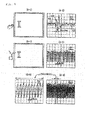
- Fig. 1 shows a door in which an impulse sensor for detecting approach of a human hand to the door is installed, and an example of a detection signal of the sensor.
- (A-1) shows a state that the human hand approaches to the door. In this case, it is assumed that the impulse sensor is installed in the neighborhood of the knob of the door.
- (A-2) shows an output of the impulse sensor when the human hand approaches to the door as shown in (A-1). As shown in (A-2).
- a vibration waveform 100 comprising a mountain and a valley each of which has a half bandwidth of about 30 to 40 ms is detected.
- the waveforms 101 and 102 before and after the vibration wave 100 correspond to noises received by the impulse sensor.
- (B-1) shows a state that a TDMA (Time Division Multiple Access) type cellular phone approaches to this door and (B-2) shows an output of the impulse sensor when the cellular phone approaches to the door like (B-1) .
- one slot corresponds to 6.6 ms (when a frame has a period of 20 ms, and one frame is constructed by 3 slots). Accordingly, a vibration wave having a mountain or valley of about 6.6 ms in width is detected due to approach of such a cellular phone.
- (C-2) shows an output of the impulse sensor when PHS (Personal Handyphone System) approaches to this door in place of the cellular phone.
- (C-3) is a diagram of the waveform of (C-2) which is enlarged on the time axis.
- one slot corresponds to 625 ⁇ s (when the period of the frame is 5 ms, and one frame is constructed by 8 slots).
- a vibration waveform having a mountain or valley of about 625 ⁇ s in waveform width is detected by the impulse sensor due to approach of such PHS.
- Communication equipment such as a cellular phone, PHS or the like serves as an oscillation source for interference waves to the impulse sensor.
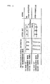
- Fig. 2 shows a processing result of a detection signal of a conventional impulse sensor containing a band pass filter.
- the upper stage of Fig. 2 shows the processing of the band pass filter to which an interference wave having small power is input.
- the interference wave is removed by the band pass filter, and thus the signal passed through the band pass filter does not reach a threshold value. Accordingly, an over-operation (an operation of recognizing that a target object exists although no target object actually exists) of the impulse sensor can be prevented.
- the lower stage of Fig. 2 shows the processing of the band pass filter when an interference wave having large power is input.
- the interference wave cannot be perfectly removed by the band pass filter.
- the signal passed through the band pass filter may reach the threshold value in some cases.
- the over-operation of the impulse sensor cannot be prevented, and it is judged that a human exists although no human exists.
- the over-operation of the impulse sensor which is caused by the interference wave in the band near the band of the detection signal of the impulse sensor cannot be perfectly prevented.
- an object of the present invention pays attention to the signal characteristic of a sensor for detecting approach of a detection target and proposes a signal processing technique of solving the problem of the prior art. That is, an object of the present invention is to provide a technique in which even noises in a band proximate to the detection signal of a sensor for detecting approach of a detection target by emission of electromagnetic wave or light and reception of the reflected wave can be easily and surely removed.
- the present invention is a processing device that is connected to a sensor for generating an electrical signal varying in connection with approach of a detection target and processes the electrical signal, and comprises means for extracting the electrical signal from a superposition signal in which the electrical signal varying in connection with the approach of the detection target and a high frequency signal higher in frequency than the electrical signal are superposed, and means for judging the approach of the detection target from the waveform of the electrical signal.
- the processing device extracts the electrical signal from the signal in which the electrical signal varying in connection with the approach of the detection target and the high frequency signal higher in frequency than the electrical signal concerned are superposed, and judges the approach of the detection target from the waveform of the electrical signal. Therefore, the approach of the detection target can be judged with removing the effect of the high frequency signal.
- the present invention may be a target object detecting device that comprises a sensor for generating an electrical signal varying in connection with approach of a detection target, means for extracting the electrical signal from a superposition signal in which the electrical signal varying in connection with the approach of the detection target and a high frequency signal higher in frequency than the electrical signal are superposed, and means for judging the approach of the detection target from the waveform of the electrical signal.
- the senor may be equipped with a generator for generating an impulse signal at a predetermined time interval, an emitting portion for emitting the impulse signal, a receiving portion for receiving a reflection signal of the emitted impulse signal from a detection target, and a detecting portion for generating an electrical signal varying with the impulse signal and the reflection signal.
- a generator for generating an impulse signal at a predetermined time interval
- an emitting portion for emitting the impulse signal
- a receiving portion for receiving a reflection signal of the emitted impulse signal from a detection target
- a detecting portion for generating an electrical signal varying with the impulse signal and the reflection signal.
- the emitting portion may emit the impulse signal by electromagnetic wave or light
- the receiving portion may receive the reflection signal of electromagnetic wave or light
- the sensor may be mounted in opening/closing operation means for an entrance of a building, opening/closing operation means for a platform of a vehicle, opening/closing operation means for a platform of a ship, opening/closing operation means of a platform of passenger transporting means, opening/closing operation means for an entrance of transporting means or operating means for operating a predetermined operation target object.
- the senor may be mounted in the outer wall of an entrance opening/closing portion at which operating means providing an opening/closing function of an entrance of a building is disposed, in the outer wall of an platform opening/closing portion at which opening/closing operation means of an entrance of a vehicle is disposed, in the outer wall of a platform opening/closing portion at which opening/closing operation means of a platform of a ship is disposed, in the outer wall of a platform opening/closing portion at which operation means providing an opening/closing function of a platform of passenger transporting means is disposed, in the outer wall of an entrance opening/closing portion at which operating means providing an opening/closing function of an entrance of transporting means is disposed, or in a housing in which operating means providing a function of operating a predetermined operation target object is disposed.
- the sensor is provided to these opening/closing operation means, in the outer walls to which the opening/closing operating means is disposed or in the housing, whereby the approach of the detection target which will operate these opening/closing operation means can be surely detected.
- the noises in the band near to the detection signal band of the sensor can be easily and surely removed.
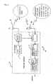
- Fig. 3 is a diagram showing the principle of this embodiment
- Fig. 4 is a diagram showing the principle construction of an impulse sensor 10 according to an embodiment.
- (A-1) and (A-2) are the same as shown in Fig. 1, and show examples of a door in which the impulse sensor is installed and a detection signal of the sensor.
- (B-4) shows a detection signal (the period is equal to about several tens ms) associated with the approach of the hand, the detection signal being superposed on the high-frequency noise (the period is equal to 20 ms and one slot is equal to about 6.6 ms) and indicated in the neighborhood of a circle 100.
- (C-5) shows a detection signal caused by the approach of the hand superposed on a high-frequency noise (the period is equal to 5 ms and one slot is equal to about 625 ⁇ s) in the neighborhood of a circle 101.
- a detection signal having a relatively low frequency which is caused by the approach of a hand appears as a variation of an envelope curve at an upper side (or lower side) of a noise having a high frequency when the approach of the hand is detected by the impulse sensor.
- the approach of the hand could be accurately detected by the impulse sensor if the detection signal of the low frequency which is caused by the approach of the hand can be separated and extracted.
- the impulse sensor 10 has a sensor circuit 11, a transmission antenna 32, and a reception antenna 33.
- the sensor circuit 11 has a local oscillator 1, an impulse generator 2, a detector 3, an approaching object variation extracting portion 7 and an approaching object presence or absence judging portion 8.
- the local oscillator 1 generates a reference clock of impulse radar.
- the impulse generator 2 forms a predetermined rectangular wave from reference clocks generated in the local oscillator 1 (plural clock pulses are made continuous, and high frequency pulses continuing for a predetermined period and corresponding to the rectangular wave is formed), and input to the transmission antenna 32. Accordingly, the transmission antenna 32 is turned on and off for the predetermined period corresponding to the rectangular wave, and a transmission wave is radiated.
- the transmission wave thus radiated is reflected by a human hand or the like as a detection target, and received as a reflection wave from the reception antenna 33.
- the detector 3 detects a reflection wave signal on the basis of the reception signal received from the reception antenna 33 and the high frequency pulse from the impulse generator 2.
- the detector 3 is implemented by a beat generating circuit of a transmission clock and a reception clock and a sample hold circuit.
- the phase thereof with respect to the signal of the local oscillator 1 or the impulse generator 2 is varied by the motion of a human hand as a detection target.
- the reflection wave signal is varied in connection with the motion of the human hand.
- the amplitude of the reflection wave signal is the value corresponding to the dielectric constant of the human hand or the like as the detection target.
- a reflection wave signal is detected while superposed on an interference wave having a high frequency as shown in Fig. 3.
- the approaching object variation extracting portion 7 extracts the reflection wave signal portion from the superposition signal of the reflection wave signal and the high-frequency interference wave.
- the approaching object presence or absence judging portion 8 judges that a detection object such as a human hand or the like is detected.
- FIG. 5 is a diagram showing an impulse sensor 10 according to this embodiment in which a binary integration unit is mounted
- Fig. 6 shows an example of the processing of processing the detection signal of the impulse sensor 10 according to this embodiment by the binary integration unit.
- the impulse sensor 10 has a sensor circuit 11, a transmission antenna 32 and a reception antenna 33.
- the sensor circuit 11 comprises a local oscillator 1, an impulse generator 2, a detector 3, a binary processor 5, an integration processor 6, and a threshold value judging portion 4.
- the transmission antenna 32, the reception antenna 33, the local oscillator 1, the impulse generator 2 and the detector 3 have the same constructions as shown in Fig. 4, and the description thereof is omitted.
- the binary processor 5, the integration processor 6 and the threshold value judging portion 4 are provided as the constituent elements corresponding to the approaching object variation extracting portion 7 and the approaching object presence or absence judging portion 8 as shown in Fig. 5.
- the output of the detector 3 (hereinafter referred to as detection signal) is input to the binary processor 5.
- the binary processor 5 has a comparator, and binarizes the output of the detector 3 to high potential or low potential in accordance with whether the detection signal is equal to a predetermined value or more (exceeds a predetermined value).
- the binarization generates a signal having a rectangular shape.
- the integration processor 6 is a so-called analog integration circuit, and integrates a signal input from the binarization processor (hereinafter referred to as binary signal).
- the binarization processor 5 and the integration processor 6 are called as a binarization integration unit.
- the binary signal has the shape corresponding to a combination of plural rectangular waveforms, and the signal after the integration becomes a ramp waveform (so-called sawtooth wave).
- the slope of the sawtooth wave has a predetermined value dependent on the time constant of the integration circuit of the integration processor 6. Accordingly, when the width of the rectangular shape of the binary signal is large (the time corresponding to the width of the rectangle is long), the variation amount of the ramp waveform (the variation amount of the output value) increases. That is, the height of the mountain of the sawtooth wave is high (the depth of the valley is deep).
- the variation of the ramp waveform decreases. That is, the height of the mountain of the sawtooth wave is low (the depth of the valley is shallow).
- the threshold value judging portion 4 contains a comparator, for example, and outputs a high-potential (H) or low potential (LO) signal in accordance with whether the output of the detector 3 is above a predetermined value or not (whether it exceeds a predetermined value or not).
- H high-potential
- LO low potential
- the threshold value judging portion 4 to which the output of the integration processor 6 (hereinafter referred to as integration signal) is input with respect to the binary signal whose rectangular waveform has a sufficiently large width, the integration signal value thereof after the binary signal integration exceeds a predetermined threshold value.
- the integration signal value thereof after the binary signal integration does not exceed the predetermined threshold value.
- Fig. 6 shows a processing example achieved by processing the detection signal of the impulse sensor 10 (detector 3) by the binarization integration unit.
- the upper stage shows the signal waveform when a hand is approached.
- the detector 3 outputs a vibration waveform 100 having a mountain and a valley of about 30 ms to 40 ms in half width to the peak.
- the rectangular signal 120 is generated by binarizing the vibration waveform 100 with a predetermined slice level 110. Then, by integrating the rectangular signal 120, the ramp waveform 130 is generated.
- the ramp waveform continuously varies with a predetermined slope for a section during which the rectangular waveform of the rectangular signal continues (for example, during the section 121, 122). As a result, the ramp waveform starts from an initial value 131 and reaches a threshold value 132, for example.
- the section of ON after the ramp waveform reaches the threshold value 132 (the section indicated by a character "ON" in Fig. 6) is dependent on the width of the rectangular signal 120, thus the width of the waveform of the detection signal (for example, a half width).
- the processing for an interference wave 200 is shown at the lower stage of Fig. 6.
- the detection signal With respect to the interference wave 200 caused by a cellular phone, the detection signal has a waveform of about 6.6 ms in width. With respect to the interference wave 200 caused by PHS, the detection signal has a waveform of about 625 ⁇ s.
- a rectangular signal 210 having a narrower width is generated as compared with the detection achieved when a hand is approached. Accordingly, even when the rectangular signal 210 is integrated by the integration circuit having the same time constant as when the hand is approached, the section of the rectangle is finished before the integration signal value output reaches the threshold value because the rectangle width of the rectangular signal 210 is narrow. As a result, the threshold judging portion 4 is not set to ON.
- the impulse sensor 10 containing the binarization integration unit discriminates the signal on the basis of the time width, and exercises the stable interference wave removing function irrespective of the magnitude of power of the interference wave.
- the noses in a band proximate to the detection signal band of the impulse sensor for example, the period of the fundamental wave ranges from 30 ms to 40 ms
- the threshold value of the threshold value judging portion 4 can be surely discriminated by combining the time constant of the integration processor 6 and the threshold value of the threshold value judging portion 4.
- the binarization processor 5 is constructed by the comparator
- the integration processor 6 is constructed by the analog integration circuit.
- the embodiment of the present invention is not limited to the above construction.
- the signal binary processor 5 and the integration processor 6 may be implemented by signal processing on digital data, for example, a signal processing program installed in DSP (Digital Signal Processor).
- the binarization integration is applied to the target object detection processing based on the impulse type radar.
- the embodiment of the present invention is not limited to the above mode.
- the present invention may be implemented in a sensor for emitting light and receiving the reflection waveform thereof.
- FIG. 1 An embodiment 2 of the present invention will be described with reference to Figs. 7 to 9.
- the construction of the sensor circuit 11 for discriminating the detection signal and the processing example thereof are shown by the binarization processor 5, the integration processor 6 and the threshold value judging portion 4 even when the noise in the band approximate to the band of the detection signal of the impulse sensor 10 is superposed on the detection signal.
- the integration processor 6 and the threshold value judging portion 4 by analyzing a waveform shape, a reflection wave signal is extracted from a signal in which a high-frequency noise of a higher band than the reflection wave signal is superposed on the reflection wave signal.
- the other construction and action of this embodiment are the same as those of the embodiment 1. Therefore, the same constituent elements are represented by the same reference numerals, and the description thereof is omitted.
- Fig. 7 is a diagram showing the construction of an impulse sensor 10A according to this embodiment.
- the impulse sensor 10A is different from the embodiment 1 in that the sensor circuit 11A has an A/D converter 15 for receiving a detection signal of the detector 3, an operating portion 16 for processing the detection signal converted to digital data by the A/D converter 15 and an approaching object presence or absence judging portion 8 for judging the presence or absence of an approaching object on the basis of the output signal of the operating portion 16.
- the A/D converter 15 converts the detection signal detected by the detector 3 into digital data.
- the operating portion 16 is implemented by CPU (Central Processing Unit), DSP (Digital Signal Processor) or the like, and executes the signal processing on the detection signal converted to the digital data. For example, the operating portion 16 extracts an envelop curve signal from a waveform like (B-4) (C-5) shown in Fig. 3.
- the approaching object judging portion 8 judges the presence or absence of the approaching object from the result of the signal processing in the operating portion 16. For example, the approaching object judging portion 8 detects the presence or absence of the approaching object by judging whether the envelop curve signal extracted by the operating portion 16 satisfies a predetermined standard.
- the operating portion 16 and the approaching object presence or absence judging portion 8 are shown by different function blocks, however, the operating portion 16 and the approaching object judging portion 8 may be a signal processing program executed on single CPU. Furthermore, these may be a signal processing program executed on single DSP. Still furthermore, the operating portion 16 and the approaching object presence or absence judging portion 8 may be implemented by hardware such as an addition/subtraction circuit, a multiplying circuit, a logical operation circuit or the like.
- Fig. 8 shows a flowchart showing the processing executed in the approaching object presence or absence judging portion 8.
- the detection signal (electrical signal) converted to the digital data are input from the A/D converter 15 to the operating portion 16 by the minute.
- the operating portion 16 shapes the waveform of the detection signal converted to the digital data and delivers it to the approaching object presence or absence judging portion 8.
- the operating portion 16 extracts an envelop curve signal from the detection signal converted to the digital data.
- the extracting procedure of the envelop curve is broadly known, and thus the description thereof is omitted.
- the approaching object presence or absence judging portion 8 successively takes in the detection signal at each time (the electrical signal corresponding to the envelop curve during unit time section) (S1). Subsequently, the approaching object presence or absence judging portion 8 judges whether the detection signal is smaller than a predetermined threshold value Vth1 (S2). If the detection signal is not smaller than the predetermined threshold value Vth1, the approaching object presence or absence judging portion 8 returns the control to S1, and processes the next detection signal.
- the approaching object presence or absence judging portion 8 adds the unit time of the electrical signal and calculates the continuing time (S3).
- This continuing time is a time for which the detection signal is continuously lower than the threshold value Vth1.
- the operating portion 8 judges whether the continuing time is larger than a predetermined threshold value Tth (S4).
- the approaching object presence or absence judging portion 8 When the continuing time is not larger than the predetermined threshold value Tth, the approaching object presence or absence judging portion 8 returns the control to S1 to process the next detection signal. On the other hand, when the continuing time is larger than the predetermined threshold value Vth, the approaching object presence or absence judging portion 8 detects that the object approaches (S5). The above processing is finished when the power source is turned off.
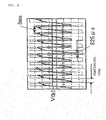
- Fig. 9 shows the relationship between Vth1 and the continuing time.
- Fig. 9 is an enlarged view of the waveform of (B-4) (C-5) shown in Fig. 3.
- the threshold value Vth1 is a reference value for the value of the detection signal (for example, the voltage value).
- the continuing time is a time for which the detection signal is continuously lower than this threshold value Vth1.
- the continuing time is equal to about 30 to 40 ms.
- the presence or absence of the approaching object is judged in accordance with whether the envelop curve of a detection signal of the detector 3 is lower than the predetermined threshold value Vth1 for a time longer than the predetermined time Tth. Accordingly, even when the reflection wave signal of the approaching object is detected as an envelop curve at the upper side of the high-frequency noise as shown in (B-4)(C-5) of Fig. 3, the presence or absence of an approaching object can be surely detected.
- Fig. 10 shows an example in which the transmission antenna 32 and the reception antenna 33 of the impulse sensor 10 are accommodated in a projection of a push button switch 40.
- the sensor circuit 11 of the impulse sensor 10 may be accommodated in the projection or provided at another position, for example, on a control board (not shown).
- Such a push button is used as opening/closing operation means at an entrance of a building, opening/closing operation means at a platform of a vehicle, opening/closing operation means at a platform of a ship, opening/closing operation means at a platform of passenger transport means, opening/closing operation means at an entrance of transport means or as operating means for operating a predetermined operation target object. Accordingly, by accommodating the impulse sensor 10 (at least the transmission antenna 32 and the reception antenna 33) in the push button switch 40, a part of a human who approaches to operate these machines or facilities can be detected.
- Fig. 11 shows an example in which the transmission antenna 32 and the reception antenna 33 of the impulse sensor 10 are accommodated in a door handle 41.
- the sensor circuit 11 of the impulse sensor 10 may be stored in the door handle 41 or provided at another position, for example, on a control board (not shown).
- the shape of the door handle 41 is not limited to the handle type (rod shape) as shown in Fig. 11, and it may be applied to various shapes such as a lever type, a knob type, a bar type, a flap type, etc.
- the impulse sensor 10 (at least the transmission antenna 32 and the reception antenna 33) in the door handle 41 as shown in Fig. 11, the motion of a part of a human body approaching from all sides to the door handle 41 can be detected.
- Fig. 12 shows an example in which the transmission antenna 32 and the reception antenna 33 of the impulse sensor 10 are accommodated in a door having a door handle 41 mounted thereon.
- the impulse sensor 10 (or at least the transmission antenna 32 and the reception antenna 33) are installed in the wall portion on which the door handle serving as an operating portion to be operated by a human like the inside of the door shown in Fig. 11, whereby a part of a human body approaching from the front side of the wall portion can be detected.
- the shape of the door handle 41 is not limited to the handle type (rod type) as shown in Fig. 12, and it may be applied to various kinds of shapes such as a lever type, a knob type, a bar type, a flap type, etc.
- Fig. 13 shows a list of examples of the door handle as examples of the operating portion to which the impulse sensor 10 (or at least the transmission antenna 32 and the reception antenna 33) is applied.
- the impulse sensor 10 (or at least the transmission antenna 32 and the reception antenna 33) may be installed in each of the lever type, the knob type, the bar type and the flap type as the door handle as shown in Fig. 13.
- the impulse sensor 10 may be provided at a position to which the human hand surely approaches.
- it may be provided inside the lever 50 of a lever type knob handle, or inside a rotational shaft 51 supporting the lever 50, or, furthermore, inside a knob 52, or inside a rotational shaft 53 supporting the knob 52.
- the impulse sensor 10 is preferably provided in the bar 55.
- the flap type door handle it is provided to the back side of a flap 56, inside a housing portion 57 for supporting the flap 56 or the like.
- the impulse sensor 10 may be provided in the door on which the door handle is set.
- the above embodiments are mainly directed to the detection processing when a part of a human body, for example, a human hand or the like approaches.
- the detection target is not limited to a human.
- the gain of the reflection wave may be adjusted on the basis of the dielectric constant. Accordingly, the present invention may be applied to the detection processing for various targets such as animals other than the human beings, machines, etc.
Landscapes
- Engineering & Computer Science (AREA)
- Remote Sensing (AREA)
- Radar, Positioning & Navigation (AREA)
- General Physics & Mathematics (AREA)
- Physics & Mathematics (AREA)
- Computer Networks & Wireless Communication (AREA)
- Life Sciences & Earth Sciences (AREA)
- Geophysics (AREA)
- General Life Sciences & Earth Sciences (AREA)
- Geology (AREA)
- Environmental & Geological Engineering (AREA)
- Geophysics And Detection Of Objects (AREA)
- Power-Operated Mechanisms For Wings (AREA)
- Burglar Alarm Systems (AREA)
- Alarm Systems (AREA)
- Radar Systems Or Details Thereof (AREA)
Applications Claiming Priority (2)
| Application Number | Priority Date | Filing Date | Title |
|---|---|---|---|
| JP2003380398 | 2003-11-10 | ||
| PCT/JP2004/016639 WO2005045473A1 (ja) | 2003-11-10 | 2004-11-10 | 処理装置および対象物検出装置 |
Publications (2)
| Publication Number | Publication Date |
|---|---|
| EP1731925A1 true EP1731925A1 (de) | 2006-12-13 |
| EP1731925A4 EP1731925A4 (de) | 2009-01-14 |
Family
ID=34567233
Family Applications (1)
| Application Number | Title | Priority Date | Filing Date |
|---|---|---|---|
| EP04818244A Withdrawn EP1731925A4 (de) | 2003-11-10 | 2004-11-10 | Verarbeitungseinrichtung und objektdetektionseinrichtung |
Country Status (4)
| Country | Link |
|---|---|
| US (1) | US20080129500A1 (de) |
| EP (1) | EP1731925A4 (de) |
| JP (1) | JPWO2005045473A1 (de) |
| WO (1) | WO2005045473A1 (de) |
Families Citing this family (3)
| Publication number | Priority date | Publication date | Assignee | Title |
|---|---|---|---|---|
| JP4711128B2 (ja) * | 2005-11-24 | 2011-06-29 | アイシン精機株式会社 | 自動ドアの挟み込み検出装置 |
| US8330600B2 (en) | 2006-11-29 | 2012-12-11 | Raytheon Company | Cold noise source system |
| JP6740895B2 (ja) * | 2016-12-27 | 2020-08-19 | Tdk株式会社 | 金属異物検出装置、ワイヤレス給電装置、ワイヤレス受電装置、及びワイヤレス電力伝送システム |
Family Cites Families (21)
| Publication number | Priority date | Publication date | Assignee | Title |
|---|---|---|---|---|
| US2562188A (en) * | 1945-12-27 | 1951-07-31 | Harold V Hance | Time base generator |
| US3852592A (en) * | 1973-06-07 | 1974-12-03 | Stanley Works | Automatic door operator |
| US4107684A (en) * | 1977-05-02 | 1978-08-15 | E-Systems, Inc. | Phase locked detector |
| US4238723A (en) * | 1977-11-30 | 1980-12-09 | Jenks William C | Power control system |
| US4216387A (en) * | 1977-12-20 | 1980-08-05 | Reed Lockwood W | Sawtooth waveform generator |
| IL113653A (en) * | 1994-05-30 | 1998-10-30 | Cerberus Ag | Active infrared sensor |
| JPH08159871A (ja) * | 1994-12-04 | 1996-06-21 | Horiba Ltd | 焦電型赤外線検出器 |
| DE19537615B4 (de) * | 1995-10-09 | 2005-02-17 | Sick Ag | Verfahren zum Betrieb eines optischen Lichttasters |
| DE69809748T2 (de) * | 1997-07-18 | 2003-09-11 | Kohler Co., Kohler | Radarvorrichtung für niedrige leistungsverwendungen und sanitäranlagen |
| JP2001194450A (ja) * | 2000-01-13 | 2001-07-19 | Toto Ltd | 可動体検知装置、トイレ装置、及びトイレ室 |
| US6362735B2 (en) * | 2000-01-21 | 2002-03-26 | Rosario G. Sicuranza | Vehicle door stop safety system |
| JP2001222775A (ja) * | 2000-02-09 | 2001-08-17 | Omron Corp | 盗難防止装置、カバンおよび展示台 |
| JP2001254549A (ja) * | 2000-03-10 | 2001-09-21 | Omron Corp | 制御装置 |
| JP2002243536A (ja) * | 2001-02-19 | 2002-08-28 | Ngk Spark Plug Co Ltd | 超音波伝播時間測定方法及びガス濃度センサ |
| US6456231B1 (en) * | 2001-06-01 | 2002-09-24 | Mcewan Technologies, Llc | Radar sensor having a CFAR detector |
| JP2003107150A (ja) * | 2001-09-27 | 2003-04-09 | Hitachi Metals Ltd | マイクロ波センサ、マイクロ波センサ用部材及びマイクロ波センサ応用機器 |
| JP2003185735A (ja) * | 2001-10-12 | 2003-07-03 | Sony Corp | 侵入物検出システムおよびその方法と受信装置 |
| US6697013B2 (en) * | 2001-12-06 | 2004-02-24 | Atheros Communications, Inc. | Radar detection and dynamic frequency selection for wireless local area networks |
| CN100476153C (zh) * | 2001-12-10 | 2009-04-08 | 欧姆龙株式会社 | 物体探测装置及控制装置 |
| JP4022859B2 (ja) * | 2002-03-19 | 2007-12-19 | オムロン株式会社 | ドアロック制御装置 |
| JP4196172B2 (ja) * | 2003-01-10 | 2008-12-17 | オムロン株式会社 | 検知装置及び錠制御装置 |
-
2004
- 2004-11-10 WO PCT/JP2004/016639 patent/WO2005045473A1/ja not_active Ceased
- 2004-11-10 EP EP04818244A patent/EP1731925A4/de not_active Withdrawn
- 2004-11-10 JP JP2005515356A patent/JPWO2005045473A1/ja active Pending
- 2004-11-10 US US11/547,426 patent/US20080129500A1/en not_active Abandoned
Also Published As
| Publication number | Publication date |
|---|---|
| JPWO2005045473A1 (ja) | 2007-05-17 |
| EP1731925A4 (de) | 2009-01-14 |
| WO2005045473A1 (ja) | 2005-05-19 |
| US20080129500A1 (en) | 2008-06-05 |
Similar Documents
| Publication | Publication Date | Title |
|---|---|---|
| JP6533759B2 (ja) | モーションセンサ、車両制御装置、車両使用者の挙動判別方法 | |
| US7339517B2 (en) | Radar | |
| US6618003B2 (en) | Method of detecting interference conditions of a radar device and a radar device | |
| EP0901642B1 (de) | Homodyner impulsfeldstörungssensor | |
| US8125375B2 (en) | Radar | |
| Won et al. | Range resolution improvement of a 24 GHz ISM band pulse radar—A feasibility study | |
| KR20060085679A (ko) | 근접 센서 | |
| US4698632A (en) | Radar detector | |
| US6400305B1 (en) | Wide band radar detector with three-sweep input stage | |
| JP2002507728A (ja) | 差動パルスレーダー動きセンサー | |
| MXPA97001648A (en) | Intervalo gate field disturbance sensor with deinterv sensitivity compensation | |
| US11480654B2 (en) | Radar transceiver | |
| US20080129500A1 (en) | Processing Device And Object Detection Device | |
| US6087976A (en) | Radar object detection system having normalized range sensitivity | |
| JP2000009828A (ja) | レーダ装置および物体探知方法 | |
| Guidi et al. | A low complexity scheme for passive UWB-RFID: Proof of concept | |
| EP3789788B1 (de) | Laserradarvorrichtung | |
| JPH07141577A (ja) | 室内侵入者検知装置 | |
| US8102905B2 (en) | Pulse detection in wireless communications system | |
| EP4321901A1 (de) | Zieldetektionsverfahren und -system | |
| JP2002277536A (ja) | 周波数変調連続波レーダ装置、リフレクタ装置およびレーダシステム | |
| JP4307443B2 (ja) | データ処理装置 | |
| RU2413242C2 (ru) | Способ обнаружения одноконтурных параметрических рассеивателей | |
| KR20250083992A (ko) | 탐지 장치 및 동작 방법 | |
| JP3044004B2 (ja) | マイクロ波検出器 |
Legal Events
| Date | Code | Title | Description |
|---|---|---|---|
| PUAI | Public reference made under article 153(3) epc to a published international application that has entered the european phase |
Free format text: ORIGINAL CODE: 0009012 |
|
| 17P | Request for examination filed |
Effective date: 20060925 |
|
| AK | Designated contracting states |
Kind code of ref document: A1 Designated state(s): DE FR GB IT |
|
| DAX | Request for extension of the european patent (deleted) | ||
| RBV | Designated contracting states (corrected) |
Designated state(s): DE FR GB IT |
|
| A4 | Supplementary search report drawn up and despatched |
Effective date: 20081212 |
|
| 17Q | First examination report despatched |
Effective date: 20090914 |
|
| STAA | Information on the status of an ep patent application or granted ep patent |
Free format text: STATUS: THE APPLICATION IS DEEMED TO BE WITHDRAWN |
|
| 18D | Application deemed to be withdrawn |
Effective date: 20100126 |