EP1731844B1 - Ofen - Google Patents
Ofen Download PDFInfo
- Publication number
- EP1731844B1 EP1731844B1 EP05025457A EP05025457A EP1731844B1 EP 1731844 B1 EP1731844 B1 EP 1731844B1 EP 05025457 A EP05025457 A EP 05025457A EP 05025457 A EP05025457 A EP 05025457A EP 1731844 B1 EP1731844 B1 EP 1731844B1
- Authority
- EP
- European Patent Office
- Prior art keywords
- air layer
- air
- partition unit
- cooking
- inlet
- Prior art date
- Legal status (The legal status is an assumption and is not a legal conclusion. Google has not performed a legal analysis and makes no representation as to the accuracy of the status listed.)
- Expired - Lifetime
Links
Images

Classifications
-
- F—MECHANICAL ENGINEERING; LIGHTING; HEATING; WEAPONS; BLASTING
- F24—HEATING; RANGES; VENTILATING
- F24C—DOMESTIC STOVES OR RANGES ; DETAILS OF DOMESTIC STOVES OR RANGES, OF GENERAL APPLICATION
- F24C15/00—Details
- F24C15/32—Arrangements of ducts for hot gases, e.g. in or around baking ovens
- F24C15/322—Arrangements of ducts for hot gases, e.g. in or around baking ovens with forced circulation
- F24C15/325—Arrangements of ducts for hot gases, e.g. in or around baking ovens with forced circulation electrically-heated
-
- F—MECHANICAL ENGINEERING; LIGHTING; HEATING; WEAPONS; BLASTING
- F24—HEATING; RANGES; VENTILATING
- F24C—DOMESTIC STOVES OR RANGES ; DETAILS OF DOMESTIC STOVES OR RANGES, OF GENERAL APPLICATION
- F24C7/00—Stoves or ranges heated by electric energy
- F24C7/04—Stoves or ranges heated by electric energy with heat radiated directly from the heating element
- F24C7/046—Ranges
-
- F—MECHANICAL ENGINEERING; LIGHTING; HEATING; WEAPONS; BLASTING
- F24—HEATING; RANGES; VENTILATING
- F24C—DOMESTIC STOVES OR RANGES ; DETAILS OF DOMESTIC STOVES OR RANGES, OF GENERAL APPLICATION
- F24C15/00—Details
- F24C15/16—Shelves, racks or trays inside ovens; Supports therefor
- F24C15/166—Shelves, racks or trays inside ovens; Supports therefor with integrated heating means
-
- F—MECHANICAL ENGINEERING; LIGHTING; HEATING; WEAPONS; BLASTING
- F24—HEATING; RANGES; VENTILATING
- F24C—DOMESTIC STOVES OR RANGES ; DETAILS OF DOMESTIC STOVES OR RANGES, OF GENERAL APPLICATION
- F24C15/00—Details
- F24C15/32—Arrangements of ducts for hot gases, e.g. in or around baking ovens
- F24C15/322—Arrangements of ducts for hot gases, e.g. in or around baking ovens with forced circulation
-
- F—MECHANICAL ENGINEERING; LIGHTING; HEATING; WEAPONS; BLASTING
- F24—HEATING; RANGES; VENTILATING
- F24C—DOMESTIC STOVES OR RANGES ; DETAILS OF DOMESTIC STOVES OR RANGES, OF GENERAL APPLICATION
- F24C15/00—Details
- F24C15/34—Elements and arrangements for heat storage or insulation
-
- F—MECHANICAL ENGINEERING; LIGHTING; HEATING; WEAPONS; BLASTING
- F24—HEATING; RANGES; VENTILATING
- F24C—DOMESTIC STOVES OR RANGES ; DETAILS OF DOMESTIC STOVES OR RANGES, OF GENERAL APPLICATION
- F24C7/00—Stoves or ranges heated by electric energy
- F24C7/06—Arrangement or mounting of electric heating elements
Definitions
- the present invention relates to an oven. More particularly, to an oven having a partition unit to partition a cooking space into a plurality of independent cooking chambers wherein the partition unit includes a heat-insulating structure to prevent heat transfer between the respective cooking chambers, whereby several kinds of food are cooked at optimum temperatures in the respective cooking chambers.
- Each oven includes a plurality of partitions mounted in a cooking space, which is partitioned into a plurality of independent cooking chambers by the partitions, whereby several kinds of food is simultaneously cooked, and therefore, cooking time is reduced.
- the above-mentioned conventional oven includes upper, middle, and lower shelves, by which a cooling space of the oven is vertically partitioned into a plurality of cooking chambers, and magnetron assemblies and electric heaters mounted at the side surfaces and the upper part of the cooling chambers, respectively, whereby several kinds of food are simultaneously cooked.
- each of the shelves to partition the cooking chambers does not include a heat-insulating structure.
- heat transfer is performed between the respective cooking chambers. Consequently, it is difficult to maintain the respective cooking chambers at optimum temperatures, and therefore, it is difficult to cook food under optimum cooking conditions.
- US application US 2002/0060215 A1 discloses a cooking oven with several cavities being separated by an insulating plate that can be removed. Furthermore, the document discloses several types of heating elements and ways to arrange them. The insulating effect of the plate is achieved by several different disclosed materials or by the means of a vacuum inside the plate.
- Patent document GB 290 340 A discloses a way of improving heat insulating devices by separating inner and outer walls of a chamber by metal sheets enabling a gap with air between the two walls. In order to reduce the quantity of heat lost by convection, the sheet divides the chamber into a plurality of horizontal compartments.
- an oven with a partition unit that insulates partitions of a cooking space in an easy and efficient way shall be provided.
- an oven having a partition unit to partition a cooking space into a plurality of independent cooking chambers wherein the partition unit includes a heat-insulating structure to prevent heat transfer between the respective cooking chambers.
- an oven including at least one partition unit to partition a cooking space into a plurality of independent cooking chambers, wherein the at least one partition unit includes an air layer defined therein and the at least one partition unit further includes first and second heat-insulating layers opposite to each other about the air layer.
- the at least one partition unit further includes an inlet and an outlet formed at the air layer while being spaced a predetermined distance from each other, whereby air is circulated in the air layer through the inlet and the outlet.
- the at least one partition unit further includes a blowing fan mounted at the inlet, whereby air is forcibly circulated in the air layer.
- the at least one partition unit further includes at least one guide member disposed in the air layer to guide air introduced into the air layer through the inlet such that the air uniformly flows throughout the air layer.
- the at least one guide member is bent from the inlet toward the outlet.
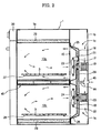
- FIG. 1 is a front view schematically illustrating the structure of an oven according to the present invention
- FIG. 2 is a sectional view taken along line II-II of FIG. 1 .
- the oven comprises a cabinet 1, formed of a box-shape having an opened front surface, the cabinet comprising a cooking space 10 defined therein, and a door 2 hingedly connected with a lower end of the cabinet 2 to open and close the opened front surface of the cabinet 1.
- the cabinet 1 and the door 2 form the outer appearance of the oven.
- the cooking space 10 is defined by a top plate 11, a bottom plate 12, two side plates 13 and 14, and a rear plate 15.
- the top plate 11 and the rear plate 15 are spaced predetermined distances from a top plate 1 a and a rear plate 1 b of the cabinet 1, respectively.
- the cooking space 10 is partitioned into a first cooking chamber 10a and a second cooking chamber 10b by a partition unit 40 disposed in the cooking space 10 to vertically partition the cooking space 10 such that different kinds of food are simultaneously cooked in the first cooking chamber 10a and the second cooking chamber 10b.
- a plurality of partition units 40 may be disposed in the cooking space 10 to partition the cooking space 10 into a larger number of independent cooking chambers.
- the partition unit 40 is connected with the side plates 13 and 14 and the rear plate 15.
- the partition unit 40 comprises a heat-insulating structure to prevent heat transfer between the first cooking chamber 10a and the second cooking chamber 10b.
- the heat-insulating structure of the partition unit 40 will be described below with reference to FIGS. 3 and 4 .
- a fan cover 16 is attached with an outside of the rear plate 15.
- First and second convection fans 17 and 18 are mounted between the rear plate 15 and the fan cover 16 to circulate air through the first cooking chamber 10a and air through the second cooking chamber 10b, respectively.
- first and second electric heaters 21 and 22 are mounted at the outer circumferences of the first and second convection fans 17 and 18 .
- First and second drive motors 19 and 20 are disposed between the fan cover 16 and the rear plate 1b of the cabinet 1 , the first drive motor 19 is connected with the first convection fan 17, and a second drive motor 20 is connected with the second convection fan 18.
- first and second suction holes 23 and 24 are formed at the upper and lower parts of the rear plate 15, which are opposite to the first and second convection fans 17 and 18, respectively. At the edge of the rear plate 15 are formed a plurality of first and second discharge holes 25 and 26.
- first and second rails 27 and 28 are provided at the side plates 13 and 14 corresponding to the lower parts of the first and second cooking chambers 10a and 10b.
- first and second rails 27 and 28 are provided to the first and second rails 27 and 28.
- racks 3 are detachably attached to the first and second rails 27 and 28 such that the racks 3 are supported by the first and second rails 27 and 28.
- Food to be cooked is placed on the racks 3 in the first and second cooking chambers 10a and 10b.
- a control panel 30 to control a cooking process.
- the first and second cooking chambers 10a and 10b which are maintained at different high temperatures, are thermally insulated by the partition unit 40. As a result, heat exchange is not performed between the first and second cooking chambers 10a and 10b, and therefore, the different kinds of food are simultaneously cooked at different optimum cooking temperatures.
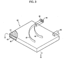
- FIG. 3 is a perspective view illustrating the partition unit shown in FIG. 2
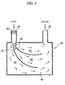
- FIG. 4 is a sectional view taken along line IV-IV of FIG. 3 .
- the partition unit 40 comprises a first heat-insulating layer 41, which forms the bottom surface of the first cooking chamber 10a disposed at the upper part of the cooking space 10, a second heat-insulating layer 42, which forms the top surface of the second cooking chamber 10b disposed at the lower part of the cooking space 10, and an air layer, having a uniform height, disposed between the first heat-insulating layer 41 and the second heat-insulating layer 42.
- the first and second heat-insulating layers 41 and 42 each comprise a material having excellent heat resistance and heat insulation properties. Consequently, heat transfer between the first and second cooking chambers 10a and 10b is maximally prevented by the first and second heat-insulating layers 41 and 42. Furthermore, the air layer 43, which is filled with air having a very low heat transfer property, is disposed between the first and second heat-insulating layers 41 and 42. Consequently, heat transfer between the first and second cooking chambers 10a and 10b is further effectively prevented by the air layer 43.
- Air is circulated through the air layer 43 to improve heat-insulating efficiency of the partition unit 40.
- an inlet 44 and an outlet 45 are formed at both side parts of the air layer 43, and a blowing fan 46 is mounted at the inlet 44.
- first and second guide members 47 and 48 are disposed in the air layer 43. Consequently, air introduced into the air layer 43 through the inlet 44 by the blowing fan 46 uniformly flows throughout the air layer 43 while being guided by the first and second guide members 47 and 48, and is then discharged out of the air layer 43 through the outlet 45.
- the first and second guide members 47 and 48 are bent from the inlet 44 to positions adjacent to the outlet 45, and a plurality of air flow channels 49, 50, and 51 is formed in the air layer 43 by the first and second guide members 47 and 48. Consequently, air introduced into the air layer 43 through the inlet 44 flows to the outlet 45 through the air flow channels 49, 50, and 51 without flow resistance.
- blowing fan 46 As the blowing fan 46 is operated, outside air is introduced into the air layer 43 through the inlet 44, flows though the air flow channels 49, 50, and 51 in the air layer 43 while being guided by the first and second guide members 47 and 48, and is then discharged out of the cabinet 1 through the outlet 45.
- a plurality of through-holes 1c through which outside air is guided to the inlet 44, and the outlet 45 extends outward through the rear plate 1b of the cabinet 1 (see FIG. 2 ).
- Heat transfer between the first and second cooking chambers 10a and 10b is prevented by the partition unit 40 with the above-stated construction. Consequently, different kinds of food are simultaneously cooked in the first and second cooking chambers 10a and 10b at optimum cooking conditions. Especially, different kinds of food are effectively cooked without being affected by each other although the difference in optimum cooking temperatures is great.
- the present invention provides an oven having a partition unit to partition a cooking space into a plurality of cooking chambers wherein the partition unit comprises a heat-insulating structure to prevent heat transfer between the respective cooking chambers. Consequently, the present invention provides the advantage of quickly and effectively cooking different kinds of food having different optimum cooking temperatures while maximally preventing heat loss.
Landscapes
- Engineering & Computer Science (AREA)
- Chemical & Material Sciences (AREA)
- Combustion & Propulsion (AREA)
- Mechanical Engineering (AREA)
- General Engineering & Computer Science (AREA)
- Electric Stoves And Ranges (AREA)
- Baking, Grill, Roasting (AREA)
Claims (8)
- Herd, der umfasst:wenigstens eine Unterteilungseinheit (40) zum Unterteilen eines Kochraums (10) in eine Vielzahl voneinander unabhängiger Kochkammern (10a, 10b),dadurch gekennzeichnet, dass
die wenigstens eine Unterteilungseinheit (40) eine darin ausgebildete Luftschicht (43) umfasst, und
die wenigstens eine Unterteilungseinheit (40) des Weiteren eine erste und eine zweite Wärmeisolierschicht (41, 42) umfasst, die einander über die Luftschicht (43) gegenüberliegen. - Herd nach Anspruch 1, wobei die wenigstens eine Unterteilungseinheit (40) des Weiteren einen Einlass (44) und einen Auslass (45) umfasst, die an der Luftschicht (43) ausgebildet und um eine vorgegebene Strecke voneinander beabstandet sind, wobei Luft in der Luftschicht (43) über den Einlass (44) und den Auslass (45) zirkuliert.
- Herd nach Anspruch 2, wobei die wenigstens eine Trenneinheit (40) des Weiteren ein an dem Einlass (44) angebrachtes Gebläse (46) umfasst, mit dem Luft zwangsweise in der Luftschicht (43) in Zirkulation gebracht wird.
- Herd nach Anspruch 3, wobei die wenigstens eine Trenneinheit (40) des Weiteren wenigstens ein Leitelement (47) umfasst, das in der Luftschicht (43) angeordnet ist, um über den Einlass (44) in die Luftschicht (43) eingeleitete Luft so zu leiten, dass die Luft in der gesamten Luftschicht (43) gleichmäßig strömt.
- Herd nach Anspruch 4, wobei das wenigstens eine Leitelement (47) von dem Einlass (44) auf den Auslass (45) zu gebogen ist.
- Herd nach Anspruch 1, der des Weiteren umfasst:ein Gehäuse (1) mit einer offenen Vorderseite;eine Tür (2) zum Öffnen und Schließen der offenen Vorderseite des Gehäuses (1);
undelektrische Heizeinrichtungen (21, 22), die in den jeweiligen Kochkammern (10a, 10b) angebracht sind, um Lebensmittel zu erhitzen, wobeidie wenigstens eine Trenneinheit (40) den Innenraum des Gehäuses (1) in eine Vielzahl unabhängiger Kochkammern (10a, 10b) unterteilt. - Herd nach Anspruch 6, wobei die wenigstens eine Trenneinheit (40) des Weiteren einen Einlass (44) und einen Auslass (45), die an der Luftschicht (43) ausgebildet und dabei um eine vorgegebene Strecke voneinander beabstandet sind, sowie ein an dem Einlass (44) angebrachtes Gebläse (46) umfasst, mit dem Luft zwangsweise in der Luftschicht (43) in Zirkulation gebracht wird.
- Herd nach Anspruch 6, wobei die wenigstens eine Trenneinheit (40) des Weiteren eine Vielzahl von Leitelementen (47, 48) umfasst, die in der Luftschicht angeordnet sind, um über den Einlass (44) in die Luftschicht (43) eingeleitete Luft so zu leiten, dass die Luft in der gesamten Luftschicht (43) gleichmäßig strömt, wobei die Leitelemente (47, 48) von dem Einlass (44) auf den Auslass (45) zu gebogen sind.
Applications Claiming Priority (1)
| Application Number | Priority Date | Filing Date | Title |
|---|---|---|---|
| KR1020050049796A KR101106636B1 (ko) | 2005-06-10 | 2005-06-10 | 오븐 |
Publications (2)
| Publication Number | Publication Date |
|---|---|
| EP1731844A1 EP1731844A1 (de) | 2006-12-13 |
| EP1731844B1 true EP1731844B1 (de) | 2009-09-02 |
Family
ID=37036941
Family Applications (1)
| Application Number | Title | Priority Date | Filing Date |
|---|---|---|---|
| EP05025457A Expired - Lifetime EP1731844B1 (de) | 2005-06-10 | 2005-11-22 | Ofen |
Country Status (5)
| Country | Link |
|---|---|
| US (1) | US7129447B1 (de) |
| EP (1) | EP1731844B1 (de) |
| KR (1) | KR101106636B1 (de) |
| DE (1) | DE602005016379D1 (de) |
| RU (1) | RU2312274C2 (de) |
Cited By (1)
| Publication number | Priority date | Publication date | Assignee | Title |
|---|---|---|---|---|
| RU196428U1 (ru) * | 2019-02-14 | 2020-02-28 | Федеральное государственное казенное военное образовательное учреждение высшего образования "Военная академия материально-технического обеспечения имени генерала армии А.В. Хрулёва" Министерства обороны Российской Федерации | Устройство для повышения коэффициента полезного действия электрической плиты |
Families Citing this family (31)
| Publication number | Priority date | Publication date | Assignee | Title |
|---|---|---|---|---|
| US20070108179A1 (en) * | 2005-03-14 | 2007-05-17 | Hines Robert S Jr | Cooking oven |
| CA2601635C (en) * | 2006-09-11 | 2015-07-07 | Moffat Pty Limited | Improved insulation for baking chambers in a multi-deck baking oven |
| WO2008066267A1 (en) * | 2006-11-29 | 2008-06-05 | Lg Electronics Inc. | Method of controlling oven |
| AU2007347943B2 (en) * | 2007-01-17 | 2011-02-24 | Lg Electronics Inc. | Oven |
| RU2350846C2 (ru) * | 2007-04-24 | 2009-03-27 | Государственное образовательное учреждение высшего профессионального образования "Санкт-Петербургский государственный университет низкотемпературных и пищевых технологий" | Электрическая плита |
| ITTO20080296A1 (it) * | 2008-04-15 | 2009-10-16 | Indesit Co Spa | Forno ventilato |
| RU2473844C2 (ru) * | 2008-09-23 | 2013-01-27 | Каваринг Кукинг Системс Б.В. | Устройство для приготовления пищи и используемый в нем элемент для направления воздуха |
| KR101617283B1 (ko) * | 2009-05-04 | 2016-05-02 | 엘지전자 주식회사 | 조리기기 및 그 운전 방법 |
| GB2482331A (en) * | 2010-07-30 | 2012-02-01 | V Group Uk Ltd | Oven for hot food delivery vehicles |
| GB2509207B (en) * | 2012-11-06 | 2014-11-05 | Alan Nuttall Ltd | Open fronted cabinet |
| US20140131345A1 (en) * | 2012-11-12 | 2014-05-15 | General Electric Company | Inductively heated divider for an oven appliance |
| KR101438675B1 (ko) * | 2012-11-30 | 2014-11-03 | 린나이코리아 주식회사 | 전기그릴용 히터구조 |
| KR101279880B1 (ko) * | 2013-01-07 | 2013-06-28 | 전성용 | 삼면포장기의 배접 상판 구조체 |
| DE102013206219A1 (de) * | 2013-04-09 | 2014-10-09 | BSH Bosch und Siemens Hausgeräte GmbH | Garraumteiler für ein Gargerät sowie Gargerät mit einem derartigen Garraumteiler |
| GB201316911D0 (en) | 2013-09-24 | 2013-11-06 | Alan Nuttall Ltd | Energy saving food storage unit |
| WO2015099648A1 (en) | 2013-12-23 | 2015-07-02 | Whirlpool Corporation | Multiple cavity microwave oven door |
| KR102208562B1 (ko) * | 2014-07-22 | 2021-01-28 | 삼성전자주식회사 | 오븐 |
| EP3497372B1 (de) | 2016-08-11 | 2021-07-07 | Whirlpool Corporation | Teileranordnung für einen mikrowellenofen |
| KR102549151B1 (ko) * | 2016-09-09 | 2023-06-30 | 삼성전자주식회사 | 조리기기 |
| CN109990595B (zh) * | 2017-12-29 | 2023-11-17 | 宁波方太厨具有限公司 | 一种烤箱风机系统 |
| CN109990596B (zh) * | 2017-12-29 | 2023-11-17 | 宁波方太厨具有限公司 | 一种烤箱风机系统 |
| CN109984628B (zh) * | 2017-12-29 | 2024-01-16 | 宁波方太厨具有限公司 | 一种烤箱风机系统 |
| US11937736B2 (en) * | 2020-03-06 | 2024-03-26 | Spectrum Brands, Inc. | Cooking appliance with conductive heating capabilities |
| RU208512U1 (ru) * | 2020-04-03 | 2021-12-22 | Федеральное государственное казенное военное образовательное учреждение высшего образования "Военный учебно-научный центр Военно-Морского Флота "Военно-морская академия им. Адмирала Флота Советского Союза Н.Г. Кузнецова" | Электрическая плита |
| CN111973003A (zh) * | 2020-08-31 | 2020-11-24 | 珠海格力电器股份有限公司 | 箱体结构及烹饪设备 |
| CN112806867A (zh) * | 2021-03-19 | 2021-05-18 | 佛山市威王日用电器有限公司 | 一种可视化的多腔节能空气炸锅 |
| US12492824B2 (en) * | 2022-04-01 | 2025-12-09 | Conair Llc | Dual door oven |
| CN116965694A (zh) * | 2022-04-24 | 2023-10-31 | 广东美的生活电器制造有限公司 | 一种烹饪器具 |
| US12504175B2 (en) | 2022-12-08 | 2025-12-23 | Whirlpool Corporation | Air-tight removable divider and thermal break |
| KR20260054299A (ko) * | 2024-10-15 | 2026-04-22 | 삼성전자주식회사 | 조리 기기 및 조리 기기의 제어방법 |
| KR102847409B1 (ko) * | 2025-05-31 | 2025-08-18 | 주식회사 다하는이사 | 이중패널구조를 이용한 창고의 공조시스템 |
Family Cites Families (15)
| Publication number | Priority date | Publication date | Assignee | Title |
|---|---|---|---|---|
| US1657205A (en) | 1925-11-12 | 1928-01-24 | Bernard Gloekler Company | Electric bake oven |
| GB290340A (en) | 1927-02-09 | 1928-05-09 | South Metropolitan Gas Co | Improvements in or relating to heat insulating devices |
| JPS57169908U (de) * | 1981-04-17 | 1982-10-26 | ||
| JPS57169908A (en) * | 1981-08-10 | 1982-10-19 | Tdk Corp | Cassette type magnetic head erasing device |
| JPS63172837A (ja) * | 1987-01-10 | 1988-07-16 | World Seiki:Kk | オ−ブン |
| IT213940Z2 (it) * | 1988-03-23 | 1990-03-01 | Trevigiana Apparecchi Riscald | Forno di cottura plurifunzionale ad ambienti separati. |
| DE4217545A1 (de) | 1992-05-27 | 1993-12-02 | Licentia Gmbh | Elektrischer Back- und Bratofen |
| US5618458A (en) * | 1994-05-10 | 1997-04-08 | Thomas; Peris W. | Cooking appliance |
| EP0685161B1 (de) * | 1994-05-19 | 1999-10-20 | Industrial Salva, S.A. | Mit zirkulierenden Verbrennungsgasen beheizter Ofen für Backwaren |
| GB2321962B (en) * | 1997-02-05 | 2000-09-20 | Destech | Cooking apparatus |
| DE19910815A1 (de) * | 1999-03-11 | 2000-09-21 | Blanco Gmbh & Co Kg | Speisentransporteinheit sowie Speisentransportwagen zur Aufnahme derartiger Speisentransporteinheiten |
| EP1172022B1 (de) | 1999-04-19 | 2007-01-17 | Enersyst Development Center, L.L.C. | Konvektions- und mikrowellenofen mit mehreren einschüben |
| JP2001311520A (ja) * | 2000-04-27 | 2001-11-09 | Toshiba Corp | 加熱調理器 |
| JP2002008846A (ja) * | 2000-06-26 | 2002-01-11 | Mitsubishi Electric Corp | 電子レンジ |
| BR0104740B1 (pt) * | 2000-10-26 | 2009-05-05 | forno de cozimento. |
-
2005
- 2005-06-10 KR KR1020050049796A patent/KR101106636B1/ko not_active Expired - Fee Related
- 2005-11-17 US US11/280,197 patent/US7129447B1/en not_active Expired - Fee Related
- 2005-11-22 DE DE602005016379T patent/DE602005016379D1/de not_active Expired - Lifetime
- 2005-11-22 EP EP05025457A patent/EP1731844B1/de not_active Expired - Lifetime
- 2005-11-29 RU RU2005137137/03A patent/RU2312274C2/ru not_active IP Right Cessation
Cited By (1)
| Publication number | Priority date | Publication date | Assignee | Title |
|---|---|---|---|---|
| RU196428U1 (ru) * | 2019-02-14 | 2020-02-28 | Федеральное государственное казенное военное образовательное учреждение высшего образования "Военная академия материально-технического обеспечения имени генерала армии А.В. Хрулёва" Министерства обороны Российской Федерации | Устройство для повышения коэффициента полезного действия электрической плиты |
Also Published As
| Publication number | Publication date |
|---|---|
| KR20060128383A (ko) | 2006-12-14 |
| DE602005016379D1 (de) | 2009-10-15 |
| RU2312274C2 (ru) | 2007-12-10 |
| RU2005137137A (ru) | 2007-06-10 |
| US7129447B1 (en) | 2006-10-31 |
| EP1731844A1 (de) | 2006-12-13 |
| KR101106636B1 (ko) | 2012-01-18 |
Similar Documents
| Publication | Publication Date | Title |
|---|---|---|
| US7129447B1 (en) | Oven | |
| US7183520B2 (en) | Oven | |
| EP2363648B1 (de) | Ofen | |
| US7102105B2 (en) | Electric oven | |
| US7686009B2 (en) | Oven with cooling door | |
| EP3302191B1 (de) | Konvektionsofen mit abnehmbaren luftkammern | |
| CA2537617C (en) | Self-cleaning over the range oven | |
| EP1672284B1 (de) | Trennwand für eine Ofenmuffel | |
| US7087863B1 (en) | Oven | |
| CA2454010C (en) | Ventilation system for a cooking appliance | |
| EP1913308B1 (de) | Kochvorrichtung | |
| KR100790391B1 (ko) | 전기오븐레인지 | |
| KR100679425B1 (ko) | 오븐 | |
| KR100730964B1 (ko) | 복수의 트레이를 갖는 오븐 | |
| KR20080021937A (ko) | 조리기기 | |
| EP0584933B1 (de) | Heizapparat eingeschlossen in einem Schrank während seiner Verwendung | |
| KR100735184B1 (ko) | 전기 오븐 | |
| JP2012007797A (ja) | 加熱装置 | |
| KR100635909B1 (ko) | 전기오븐 | |
| KR100676142B1 (ko) | 전기오븐 | |
| JP2004085111A (ja) | 加熱調理器 | |
| JPH08210643A (ja) | 加熱調理器 |
Legal Events
| Date | Code | Title | Description |
|---|---|---|---|
| PUAI | Public reference made under article 153(3) epc to a published international application that has entered the european phase |
Free format text: ORIGINAL CODE: 0009012 |
|
| AK | Designated contracting states |
Kind code of ref document: A1 Designated state(s): AT BE BG CH CY CZ DE DK EE ES FI FR GB GR HU IE IS IT LI LT LU LV MC NL PL PT RO SE SI SK TR |
|
| AX | Request for extension of the european patent |
Extension state: AL BA HR MK YU |
|
| RIN1 | Information on inventor provided before grant (corrected) |
Inventor name: KIM, CHEOL JIN Inventor name: HA, YU JEUB Inventor name: KIM, SUNG KWANG Inventor name: HWANG, YUN IC Inventor name: KIM, KYOUNG HO Inventor name: HONG, SEOK WEON Inventor name: CHO, PUNG YEUN Inventor name: PARK, SUNG SOO Inventor name: KANG, SANG HYUN Inventor name: KIM, TAE HO Inventor name: LEE, KIL YOUNG |
|
| RIN1 | Information on inventor provided before grant (corrected) |
Inventor name: KANG, SANG HYUN Inventor name: LEE, KIL YOUNG Inventor name: CHO, PUNG YEUN Inventor name: KIM, KYOUNG HO Inventor name: PARK, SUNG SOO Inventor name: KIM, TAE HO Inventor name: HONG, SEOK WEON Inventor name: HWANG, YUN IC Inventor name: KIM, CHEOL JIN Inventor name: KIM, SUNG KWANG Inventor name: HA, YU JEUB |
|
| 17P | Request for examination filed |
Effective date: 20070530 |
|
| 17Q | First examination report despatched |
Effective date: 20070628 |
|
| AKX | Designation fees paid |
Designated state(s): DE FR GB |
|
| GRAP | Despatch of communication of intention to grant a patent |
Free format text: ORIGINAL CODE: EPIDOSNIGR1 |
|
| RIN1 | Information on inventor provided before grant (corrected) |
Inventor name: HWANG, YUN IC Inventor name: KIM, CHEOL JIN Inventor name: HONG, SEOK WEON Inventor name: KIM, SUNG KWANG Inventor name: KIM, TAE HO Inventor name: CHO, PUNG YEUN Inventor name: LEE, KIL YOUNG Inventor name: KIM, KYOUNG HO Inventor name: PARK, SUNG SOO Inventor name: HA, YU JEUB Inventor name: KANG, SANG HYUN |
|
| GRAS | Grant fee paid |
Free format text: ORIGINAL CODE: EPIDOSNIGR3 |
|
| GRAA | (expected) grant |
Free format text: ORIGINAL CODE: 0009210 |
|
| AK | Designated contracting states |
Kind code of ref document: B1 Designated state(s): DE FR GB |
|
| REF | Corresponds to: |
Ref document number: 602005016379 Country of ref document: DE Date of ref document: 20091015 Kind code of ref document: P |
|
| PLBE | No opposition filed within time limit |
Free format text: ORIGINAL CODE: 0009261 |
|
| STAA | Information on the status of an ep patent application or granted ep patent |
Free format text: STATUS: NO OPPOSITION FILED WITHIN TIME LIMIT |
|
| 26N | No opposition filed |
Effective date: 20100603 |
|
| PGFP | Annual fee paid to national office [announced via postgrant information from national office to epo] |
Ref country code: FR Payment date: 20131115 Year of fee payment: 9 Ref country code: GB Payment date: 20131112 Year of fee payment: 9 Ref country code: DE Payment date: 20131113 Year of fee payment: 9 |
|
| REG | Reference to a national code |
Ref country code: DE Ref legal event code: R119 Ref document number: 602005016379 Country of ref document: DE |
|
| GBPC | Gb: european patent ceased through non-payment of renewal fee |
Effective date: 20141122 |
|
| REG | Reference to a national code |
Ref country code: FR Ref legal event code: ST Effective date: 20150731 |
|
| PG25 | Lapsed in a contracting state [announced via postgrant information from national office to epo] |
Ref country code: DE Free format text: LAPSE BECAUSE OF NON-PAYMENT OF DUE FEES Effective date: 20150602 Ref country code: GB Free format text: LAPSE BECAUSE OF NON-PAYMENT OF DUE FEES Effective date: 20141122 |
|
| PG25 | Lapsed in a contracting state [announced via postgrant information from national office to epo] |
Ref country code: FR Free format text: LAPSE BECAUSE OF NON-PAYMENT OF DUE FEES Effective date: 20141201 |