EP1731366A1 - Apparatus and method for displaying images - Google Patents
Apparatus and method for displaying images Download PDFInfo
- Publication number
- EP1731366A1 EP1731366A1 EP06252939A EP06252939A EP1731366A1 EP 1731366 A1 EP1731366 A1 EP 1731366A1 EP 06252939 A EP06252939 A EP 06252939A EP 06252939 A EP06252939 A EP 06252939A EP 1731366 A1 EP1731366 A1 EP 1731366A1
- Authority
- EP
- European Patent Office
- Prior art keywords
- obstacle
- image
- bird
- vehicle
- eye view
- Prior art date
- Legal status (The legal status is an assumption and is not a legal conclusion. Google has not performed a legal analysis and makes no representation as to the accuracy of the status listed.)
- Withdrawn
Links
- 238000000034 method Methods 0.000 title claims abstract description 22
- 240000004050 Pentaglottis sempervirens Species 0.000 claims abstract description 151
- 235000004522 Pentaglottis sempervirens Nutrition 0.000 claims abstract description 151
- 230000008859 change Effects 0.000 claims description 12
- 238000001514 detection method Methods 0.000 description 35
- 238000010586 diagram Methods 0.000 description 12
- 238000006243 chemical reaction Methods 0.000 description 7
- 230000003466 anti-cipated effect Effects 0.000 description 5
- 238000012986 modification Methods 0.000 description 2
- 230000004048 modification Effects 0.000 description 2
- 238000002360 preparation method Methods 0.000 description 2
- 241001465754 Metazoa Species 0.000 description 1
- 230000015572 biosynthetic process Effects 0.000 description 1
- 230000003247 decreasing effect Effects 0.000 description 1
- 230000000694 effects Effects 0.000 description 1
- 230000006870 function Effects 0.000 description 1
- 238000010191 image analysis Methods 0.000 description 1
- 230000008569 process Effects 0.000 description 1
- 238000003786 synthesis reaction Methods 0.000 description 1
- 230000002194 synthesizing effect Effects 0.000 description 1
- 230000009466 transformation Effects 0.000 description 1
Images


Classifications
-
- G—PHYSICS
- G06—COMPUTING; CALCULATING OR COUNTING
- G06T—IMAGE DATA PROCESSING OR GENERATION, IN GENERAL
- G06T3/00—Geometric image transformations in the plane of the image
- G06T3/40—Scaling of whole images or parts thereof, e.g. expanding or contracting
- G06T3/4038—Image mosaicing, e.g. composing plane images from plane sub-images
-
- B—PERFORMING OPERATIONS; TRANSPORTING
- B60—VEHICLES IN GENERAL
- B60R—VEHICLES, VEHICLE FITTINGS, OR VEHICLE PARTS, NOT OTHERWISE PROVIDED FOR
- B60R1/00—Optical viewing arrangements; Real-time viewing arrangements for drivers or passengers using optical image capturing systems, e.g. cameras or video systems specially adapted for use in or on vehicles
- B60R1/20—Real-time viewing arrangements for drivers or passengers using optical image capturing systems, e.g. cameras or video systems specially adapted for use in or on vehicles
- B60R1/22—Real-time viewing arrangements for drivers or passengers using optical image capturing systems, e.g. cameras or video systems specially adapted for use in or on vehicles for viewing an area outside the vehicle, e.g. the exterior of the vehicle
- B60R1/23—Real-time viewing arrangements for drivers or passengers using optical image capturing systems, e.g. cameras or video systems specially adapted for use in or on vehicles for viewing an area outside the vehicle, e.g. the exterior of the vehicle with a predetermined field of view
- B60R1/26—Real-time viewing arrangements for drivers or passengers using optical image capturing systems, e.g. cameras or video systems specially adapted for use in or on vehicles for viewing an area outside the vehicle, e.g. the exterior of the vehicle with a predetermined field of view to the rear of the vehicle
-
- B—PERFORMING OPERATIONS; TRANSPORTING
- B60—VEHICLES IN GENERAL
- B60R—VEHICLES, VEHICLE FITTINGS, OR VEHICLE PARTS, NOT OTHERWISE PROVIDED FOR
- B60R1/00—Optical viewing arrangements; Real-time viewing arrangements for drivers or passengers using optical image capturing systems, e.g. cameras or video systems specially adapted for use in or on vehicles
- B60R1/20—Real-time viewing arrangements for drivers or passengers using optical image capturing systems, e.g. cameras or video systems specially adapted for use in or on vehicles
- B60R1/22—Real-time viewing arrangements for drivers or passengers using optical image capturing systems, e.g. cameras or video systems specially adapted for use in or on vehicles for viewing an area outside the vehicle, e.g. the exterior of the vehicle
- B60R1/23—Real-time viewing arrangements for drivers or passengers using optical image capturing systems, e.g. cameras or video systems specially adapted for use in or on vehicles for viewing an area outside the vehicle, e.g. the exterior of the vehicle with a predetermined field of view
- B60R1/27—Real-time viewing arrangements for drivers or passengers using optical image capturing systems, e.g. cameras or video systems specially adapted for use in or on vehicles for viewing an area outside the vehicle, e.g. the exterior of the vehicle with a predetermined field of view providing all-round vision, e.g. using omnidirectional cameras
-
- H—ELECTRICITY
- H04—ELECTRIC COMMUNICATION TECHNIQUE
- H04N—PICTORIAL COMMUNICATION, e.g. TELEVISION
- H04N7/00—Television systems
- H04N7/18—Closed-circuit television [CCTV] systems, i.e. systems in which the video signal is not broadcast
- H04N7/181—Closed-circuit television [CCTV] systems, i.e. systems in which the video signal is not broadcast for receiving images from a plurality of remote sources
-
- B—PERFORMING OPERATIONS; TRANSPORTING
- B60—VEHICLES IN GENERAL
- B60R—VEHICLES, VEHICLE FITTINGS, OR VEHICLE PARTS, NOT OTHERWISE PROVIDED FOR
- B60R2300/00—Details of viewing arrangements using cameras and displays, specially adapted for use in a vehicle
- B60R2300/10—Details of viewing arrangements using cameras and displays, specially adapted for use in a vehicle characterised by the type of camera system used
- B60R2300/102—Details of viewing arrangements using cameras and displays, specially adapted for use in a vehicle characterised by the type of camera system used using 360 degree surveillance camera system
-
- B—PERFORMING OPERATIONS; TRANSPORTING
- B60—VEHICLES IN GENERAL
- B60R—VEHICLES, VEHICLE FITTINGS, OR VEHICLE PARTS, NOT OTHERWISE PROVIDED FOR
- B60R2300/00—Details of viewing arrangements using cameras and displays, specially adapted for use in a vehicle
- B60R2300/10—Details of viewing arrangements using cameras and displays, specially adapted for use in a vehicle characterised by the type of camera system used
- B60R2300/105—Details of viewing arrangements using cameras and displays, specially adapted for use in a vehicle characterised by the type of camera system used using multiple cameras
-
- B—PERFORMING OPERATIONS; TRANSPORTING
- B60—VEHICLES IN GENERAL
- B60R—VEHICLES, VEHICLE FITTINGS, OR VEHICLE PARTS, NOT OTHERWISE PROVIDED FOR
- B60R2300/00—Details of viewing arrangements using cameras and displays, specially adapted for use in a vehicle
- B60R2300/30—Details of viewing arrangements using cameras and displays, specially adapted for use in a vehicle characterised by the type of image processing
- B60R2300/301—Details of viewing arrangements using cameras and displays, specially adapted for use in a vehicle characterised by the type of image processing combining image information with other obstacle sensor information, e.g. using RADAR/LIDAR/SONAR sensors for estimating risk of collision
-
- B—PERFORMING OPERATIONS; TRANSPORTING
- B60—VEHICLES IN GENERAL
- B60R—VEHICLES, VEHICLE FITTINGS, OR VEHICLE PARTS, NOT OTHERWISE PROVIDED FOR
- B60R2300/00—Details of viewing arrangements using cameras and displays, specially adapted for use in a vehicle
- B60R2300/30—Details of viewing arrangements using cameras and displays, specially adapted for use in a vehicle characterised by the type of image processing
- B60R2300/303—Details of viewing arrangements using cameras and displays, specially adapted for use in a vehicle characterised by the type of image processing using joined images, e.g. multiple camera images
-
- B—PERFORMING OPERATIONS; TRANSPORTING
- B60—VEHICLES IN GENERAL
- B60R—VEHICLES, VEHICLE FITTINGS, OR VEHICLE PARTS, NOT OTHERWISE PROVIDED FOR
- B60R2300/00—Details of viewing arrangements using cameras and displays, specially adapted for use in a vehicle
- B60R2300/60—Details of viewing arrangements using cameras and displays, specially adapted for use in a vehicle characterised by monitoring and displaying vehicle exterior scenes from a transformed perspective
- B60R2300/607—Details of viewing arrangements using cameras and displays, specially adapted for use in a vehicle characterised by monitoring and displaying vehicle exterior scenes from a transformed perspective from a bird's eye viewpoint
-
- B—PERFORMING OPERATIONS; TRANSPORTING
- B60—VEHICLES IN GENERAL
- B60R—VEHICLES, VEHICLE FITTINGS, OR VEHICLE PARTS, NOT OTHERWISE PROVIDED FOR
- B60R2300/00—Details of viewing arrangements using cameras and displays, specially adapted for use in a vehicle
- B60R2300/70—Details of viewing arrangements using cameras and displays, specially adapted for use in a vehicle characterised by an event-triggered choice to display a specific image among a selection of captured images
-
- B—PERFORMING OPERATIONS; TRANSPORTING
- B60—VEHICLES IN GENERAL
- B60R—VEHICLES, VEHICLE FITTINGS, OR VEHICLE PARTS, NOT OTHERWISE PROVIDED FOR
- B60R2300/00—Details of viewing arrangements using cameras and displays, specially adapted for use in a vehicle
- B60R2300/80—Details of viewing arrangements using cameras and displays, specially adapted for use in a vehicle characterised by the intended use of the viewing arrangement
- B60R2300/806—Details of viewing arrangements using cameras and displays, specially adapted for use in a vehicle characterised by the intended use of the viewing arrangement for aiding parking
-
- B—PERFORMING OPERATIONS; TRANSPORTING
- B60—VEHICLES IN GENERAL
- B60R—VEHICLES, VEHICLE FITTINGS, OR VEHICLE PARTS, NOT OTHERWISE PROVIDED FOR
- B60R2300/00—Details of viewing arrangements using cameras and displays, specially adapted for use in a vehicle
- B60R2300/80—Details of viewing arrangements using cameras and displays, specially adapted for use in a vehicle characterised by the intended use of the viewing arrangement
- B60R2300/8093—Details of viewing arrangements using cameras and displays, specially adapted for use in a vehicle characterised by the intended use of the viewing arrangement for obstacle warning
-
- G—PHYSICS
- G01—MEASURING; TESTING
- G01S—RADIO DIRECTION-FINDING; RADIO NAVIGATION; DETERMINING DISTANCE OR VELOCITY BY USE OF RADIO WAVES; LOCATING OR PRESENCE-DETECTING BY USE OF THE REFLECTION OR RERADIATION OF RADIO WAVES; ANALOGOUS ARRANGEMENTS USING OTHER WAVES
- G01S13/00—Systems using the reflection or reradiation of radio waves, e.g. radar systems; Analogous systems using reflection or reradiation of waves whose nature or wavelength is irrelevant or unspecified
- G01S13/88—Radar or analogous systems specially adapted for specific applications
- G01S13/93—Radar or analogous systems specially adapted for specific applications for anti-collision purposes
- G01S13/931—Radar or analogous systems specially adapted for specific applications for anti-collision purposes of land vehicles
- G01S2013/9314—Parking operations
Definitions
- the present invention relates to an apparatus and method for displaying images and particularly, but not exclusively, to an image display device and method for a vehicle for displaying images of the vehicle surroundings to the driver during, for example, the parking of the vehicle. Aspects of the invention also relate to a vehicle.
- Conventional technology discloses a method for processing multiple camera images of vehicle surroundings for display to the driver as described in, for example, Figure 7 of Japanese Kokai Patent Application No. 2004 254219 .
- the vehicle surrounding image-processing device described in that reference provides an image (a bird's-eye view image hereafter) from pickup devices mounted on the vehicle by converting one or more camera images into an image as if picked up from an imaginary overhead viewing point by coordinate transformation with respect to a reference plane and superimposing a computer-generated image of the vehicle prepared beforehand with computer-generated technology on the images.
- the ground surface is often used as the reference plane. Since the positional relationship between the white line, the kerb, etc., on the ground surface and the vehicle is expressed objectively, this bird's-eye view image is an effective aid when parking in a marked parking space or when moving the vehicle alongside a kerb.
- an image display device for a vehicle comprising multiple image pickup devices operable to capture multiple images of the vehicle surroundings in different directions, an image-processing device for composing a bird's-eye view image using the multiple images, a display device for providing the bird's-eye view image to the driver and an obstacle detector operative to detect obstacles in the vicinity of the vehicle; and wherein the image-processing device is operable to display simultaneously on the display device the bird's-eye view image and a direct image picked up by one of the multiple image pickup devices in the direction of an obstacle detected by the obstacle detector.
- the display device is operable to display an obstacle alarm in the bird's-eye view image to emphasize a portion of the vehicle approaching the obstacle.
- the obstacle alarm is a display concealing the portion of the vehicle approaching the obstacle in the bird's-eye view image using the direct image.
- the device may comprise at least one guideline for indicating a positional relationship of the vehicle to vehicle surroundings, the at least one guideline displayed on at least one of the bird's-eye view image and the direct image.
- the at least one guideline has a first display state; and wherein the display device is operable to change the first display state to a second display state of at least a portion of the at least one guideline when the obstacle is detected by the obstacle detector.
- the at least one guideline has a first display state; and wherein the display device is operable to erase a portion of the at least one guideline closest to the obstacle when the obstacle is detected by the obstacle detector.
- the display device is operable to flash a portion of the at least one guideline closest to the obstacle when the obstacle is detected by the obstacle detector.
- the display device is operable to change a color of a portion of the at least one guideline closest to the obstacle when the obstacle is detected by the obstacle detector.
- the display device is operable to emphasize a portion of the direct image closest the obstacle when the obstacle is detected by the obstacle detector.
- the device may comprise a line enclosing and emphasizing the portion of the direct image closest the obstacle.
- a display size of the bird's-eye view image is larger than a display size of the direct image when the obstacle is no longer detected by the obstacle detector; and wherein the display size of the direct image is larger than the display size of the bird's-eye view image when the obstacle is detected by the obstacle detector.
- the apparatus may comprise a first background color of at least one of the direct image and the bird's-eye view image; and wherein the display device is operable to change the first background color to a second background color when the obstacle is detected by the obstacle detector.
- an image display device for a vehicle comprising means for capturing vehicle surroundings from a plurality of directions, means for composing a bird's-eye view image from multiple images of the vehicle surroundings so captured, means for displaying the bird's-eye view image to the driver, means for detecting a presence of any obstacles in the vicinity of the vehicle and means for simultaneously displaying the bird's-eye view image and a direct image picked up in a direction of an obstacle when the obstacle is detected.
- an image display method for a vehicle comprising capturing vehicle surroundings from a plurality of directions, composing a bird's-eye view image from multiple images of the vehicle surroundings so captured, displaying the bird's-eye view image to the driver, detecting a presence of any obstacles in the vicinity of the vehicle and simultaneously displaying the bird's-eye view image and a direct image picked up in a direction of an obstacle when the obstacle is detected.
- the method may comprise displaying guidelines indicating a positional relationship between the vehicle and vehicle surroundings on at least one of the bird's-eye view image and the direct image.
- the method may comprise changing a display state of the guidelines when the obstacle is detected.
- changing the display state of the guidelines when the obstacle is detected further comprises at least one of erasing a portion of the guidelines closest to the obstacle when the obstacle is detected, flashing the portion of the guidelines closest to the obstacle when the obstacle is detected, and changing the color of a portion of the guidelines closest to the obstacle when the obstacle is detected.
- the method may comprise emphasizing at least a portion of the vehicle approaching the obstacle on at least one of the bird's-eye view image and the direct image.
- emphasizing at least the portion of the vehicle approaching the obstacle further comprises at least one of concealing the portion of the vehicle approaching the obstacle on the bird's-eye view image using the direct image, enclosing the portion of the direct image closest the obstacle with a line, making a display size of the direct image larger than a display size of the bird's-eye view image, and changing a background color of the display image.
- the method may comprise making a display size of the bird's-eye view image larger than a display size of the direct image when the obstacle is no longer detected.
- An image display device for a vehicle may comprise multiple cameras for pickup of multiple images in different directions of the vehicle surroundings, an image-processing device for composing a bird's-eye view image using the multiple images, a display device for providing the bird's-eye view image to the driver, and an obstacle detector operative to detect obstacles in the vicinity of the vehicle.
- the image-processing device may be operable to display simultaneously on the display device the bird's-eye view image and a direct image picked up by one of the multiple cameras in the direction of an obstacle detected by the obstacle detector.
- a method may comprise capturing vehicle surroundings with from a plurality of directions, composing a bird's-eye view image from multiple images of the vehicle surroundings so captured, displaying the bird's-eye view image to the driver, detecting a presence of any obstacles in the vicinity of the vehicle, and simultaneously displaying the bird's-eye view image and a direct image picked up in a direction of an obstacle when the obstacle is detected.
- the bumper of an SUV or another vehicle with a high bumper will appear in the bird's-eye view image at a position farther than the actual position of the bumper.
- the actual position of the driver's vehicle with respect to the position of another vehicle in the bird's-eye view image varies, there is the possibility that the predetermined path of the driver's vehicle that can be checked on the bird's-eye view image and the actual travel path will not be in agreement.
- multiple direct images are processed to compose a bird's-eye view image from which the vehicle surroundings can be made known to the driver at a glance.
- the display simultaneously displays the bird's-eye view images prepared by the image-processing means and the direct images picked up in the direction of the obstacle detected by the obstacle-detection means.
- the display means simultaneously displays the bird's-eye view images and the direct images picked up in the direction of the obstacle with respect to the vehicle. Therefore, any differences between the relative position of the obstacle in the bird's-eye view image and the relative position of the actual obstacle can be checked on the same screen.
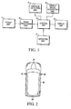
- one driving support device is constructed as shown in the block diagram of Figure 1.
- This driving support device has the function of an image display device that shows the vehicle surroundings to the driver by simultaneously displaying on the same screen a bird's-eye view image and images (to be called direct images hereafter) from the cameras mounted on various parts of the vehicle body and not subjected to image-processing as information used to check the position of the vehicle. It assists the driving operation by showing images required by the driver.
- This driving support device is provided with pickup unit 1 consisting of multiple cameras mounted on the body of the vehicle and a display unit 2 provided in a position in which the display screen provided inside the vehicle can be seen by the driver. Furthermore, in this driving support device, the control unit 3 for the overall control of the image display of the multiple camera images picked up by the pickup unit 1 is connected to the image-processing unit 4, the obstacle-detection unit 5, the vehicle signal acquisition unit 6 and the operating unit 7.
- the control unit 3 can be, for example, a standard microprocessor coupled to memory or a standard microcontroller incorporating on-board memory, where the memory stores a control program for controlling the image display as described below. Each of these parts is discussed in more detail below.
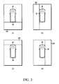
- the pickup unit 1 is comprised of the front camera 1F provided in the front portion of the vehicle 10, the rear camera 1B provided in the rear of the vehicle 10, the right side camera 1R provided on the right door mirror on the right side of the vehicle 10, and the left side camera 1L provided on the left door mirror on the left side of the vehicle 10.
- the front camera 1F, rear camera 1B, right side camera 1R and left side camera 1L are preferably so-called wide-angle cameras and are designed with a viewing angle of 180°. Of course other cameras mounted in other positions are possible.
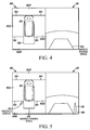
- the pickup unit 1 picks up a rear direct image (A) that includes conditions in rear pickup region 11B of the vehicle 10 with the rear camera 1B, a left side direct image (B) that includes conditions in left side pickup region 11L of the vehicle 10 with the left side camera 1L, a front direct image (C) that includes conditions in front pickup region 11F of the vehicle 10 with the front camera 1F, and a right side direct image (D) that includes conditions in the right side pickup region 11R of the vehicle 10 with the right side camera 1R.
- A rear direct image
- B left side direct image
- C front direct image
- D right side direct image
- the driving support device can acquire images of all of the vehicle surroundings.
- the images are displayed simultaneously corresponding to operations by the driver, obstacle-detection information in the obstacle-detection unit 5, etc.
- the obstacle-detection unit 5 detects the presence or absence of an obstacle in the vehicle surroundings and its position relative to the vehicle 10 (i.e., the direction and distance with respect to the vehicle 10).
- the obstacle-detection unit 5 detects obstacles, for example, by using ultrasonic or infrared sensors, or by inputting the direct images obtained by the pickup unit 1 and carrying out image analysis, etc.
- the obstacle-detection unit 5 outputs the presence or absence of an obstacle with respect to the vehicle 10 and the obstacle-detection information including the relative position to the control unit 3.
- the vehicle signal acquisition unit 6 acquires such signals as the vehicle speed, the vehicle travel direction and so on as information representing the state of the vehicle 10 and outputs them to the control unit 3.
- the image-processing unit 4 acquires multiple direct images picked up by the pickup unit 1 and image processes these images to generate a bird's-eye view image from which the vehicle surroundings can be known at a glance.
- the reader is referred to U.S. Patent Application Serial No. 11/366,091, filed March 2, 2006 , which is assigned to the current assignee and is incorporated herein in its entirety by reference.
- the image-processing unit 4 contains a prestored conversion table in which the pixel arrangement for the relationship between the input multiple direct images and the output bird's-eye view images is recorded.
- the image-processing unit 4 stores the various direct images in a specified input memory.
- These stored direct images are read in units of pixels according to the conversion table by the processing unit 4 and are stored in an output memory.
- the output memory from the front direct images, the rear direct images, the right side direct images and the left side direct images, the bird's-eye view images can be composed with cutouts of their respective necessary image regions.
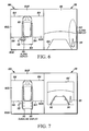
- the bird's-eye view image 100 of Figure 4 prepared by the image-processing unit 4 is an image in which the viewing point positions of four types of direct images converge at a single virtual viewing point high above the vehicle.
- Such a bird's-eye view image 100 allows the driver to view the vehicle surroundings as if the vehicle 10 were being seen from high up in the air.
- the bird's-eye view image 100 is constituted by arranging the vehicle computer-generated (CG) image 101 in the center and arranging the left side bird's-eye view image 102L, the right side bird's-eye view image 102R, the front bird's-eye view image 102F and the rear bird's-eye view image 102B, which are subjected to the viewing point conversion, around the vehicle CG image 101.
- the bird's-eye view image 100 is further constituted by providing a mask line 104 between the front bird's-eye view image 102F and both the left side bird's-eye view image 102L and the right side bird's-eye view image 102R.
- Another mask line 104 is provided between the rear bird's-eye view image 102B and both the left side bird's-eye view image 102L and the right side bird's-eye view image 102R.
- a variety of bird's-eye view images 102 can be divided into multiple regions.
- the driver can orient himself by the seams.
- other more finely divided patterns are acceptable, e.g., three or more divisions.
- the direct image 110 of the rear pickup region 11B is displayed simultaneously.
- This direct image 110 can also be that of the front pickup region 11F, the left side pickup region 11L, the right side pickup region 11R or the rear pickup region 11B, according to the shift position information or the vehicle speed signal obtained from the vehicle signal acquisition unit 6.
- the control unit 3 carries out the appropriate control measures for notifying the driver with an image or sound or the like, so that attention of the driver can be drawn, or directed, toward information used to check the positional relationship. Furthermore, the control unit 3 acquires the current state of the vehicle from the vehicle speed signal from the vehicle signal acquisition unit 6 or the shift position information from the operating unit 7. A variety of information can be provided to the driver by means of an image, sound or the like depending on given conditions.
- the control section 3 simultaneously displays the bird's-eye view image 100, and the direct image 110 that includes the obstacle. Furthermore, the control unit 3 displays the direct image with the direction in which the obstacle has been detected as the pickup region from the vehicle speed signal or the shift position information.
- the control unit 3 controls the display unit 2 to display the image obtained by combining the bird's-eye view image 100 prepared by the image-processing unit 4 and the rear direct image 110 picked up with the rear camera 1B.
- the control unit 3 controls the displays to display the bird's-eye view image 100 and the rear direct image 110 from the vehicle speed data obtained by the vehicle signal acquisition unit 6 and the shift position information from the operating unit 7, irrespective of the obstacle-detection information is contained in the obstacle-detection unit 5.
- the marked parking space display 103 appears in the left side bird's-eye view image 102L, the right side bird's-eye view image 102R, and the rear bird's-eye view image 102B.
- the obstacle display 121 is displayed in the display position in agreement with its relative position to the vehicle 10 as transmitted according to the obstacle-detection information.
- the ways in which the obstacle appears in the bird's-eye view image 100 and in the direct image 110 differ. This is due to the fact that, in the bird's-eye view image 100, the image picked up by the pickup unit 1 has been subjected to the processing required for conversion to the bird's-eye view image 100.
- the reference plane reappears in the bird's-eye view image 100 with the correct relative position. However, obstacles located above or below the reference plane do not reappear with the correct relative position.
- the pylon in the bird's-eye view image 100 in Figure 5 is a spatial body, it reappears with a distorted shape. Specifically, the front tip portion of the pylon reappears in the bird's-eye view image 100 farther away than its actual position relative to the vehicle 10. Since objects close to the camera of the pickup unit 1 mounted on the vehicle appear farther away, the bumpers of the SUVs and other vehicles with high bumpers will appear farther away in the bird's-eye view image 100 than their actual locations. In this way, there will be an error in the relative position of the driver's vehicle to the actual position of another vehicle.
- the driving support device displays the rear view of the rear side of the vehicle in the direct image 110.
- the driving support device displays the obstacle display 121 closer to its actual position by exploiting the fact that the direct image 110 has less distortion with respect to a spatial body than the bird's-eye view image 100 and appears more natural.
- the control unit 3 displays the obstacle alarm display 131 that may conceal the vicinity of the portion of the vehicle 10 in the direction of the detection of the obstacle.
- the obstacle alarm display 131 displayed in Figure 6 with a rectangular shape and color, is highlighted. Since the perceived distance between the vehicle 10 and the obstacle (the pylon) is distorted by the bird's-eye view conversion, there is the possibility of an error when the positional relationship is checked.
- the shape of the obstacle alarm display 131 can be round, L-shaped, or a variety of other shapes. Furthermore, the size of the obstacle alarm display 131 can also be changed corresponding to the distance of the vehicle 10 from the obstacle. The display can also flash corresponding to the distance of the vehicle 10 from the obstacle.
- the direct image 110 alongside the bird's-eye view image 100 displays the obstacle alarm display 132 so that the obstacle display 121 is included.
- This obstacle alarm display 132 is displayed in an ellipse so that the obstacle display 121 is emphasized.
- the obstacle alarm display 132 may also surround the obstacle display 121 with a square, triangle, etc. It may also be displayed by emphasizing the obstacle display 121 of the direct image 110 with an icon or the like. Furthermore, it is also acceptable to flash or change the highlighting color of the obstacle alarm display 132 so that the eye is directed to the direct image 110 rather than to the bird's-eye view image 100.
- the driver can assess the proximity of the vehicle 10 to the obstacle by referring to the direct image 110 rather than the bird's-eye view image 100 and errors in judgment due to the distortion of the spatial body in the bird's-eye view image 100 can thereby be inhibited.
- the bird's-eye view image 100 and the direct image 110 are displayed in parallel. However, it is also acceptable for the bird's-eye view image 100 and the direct image 110 to be displayed separately; if the displayed image is the bird's-eye view image 100, the obstacle alarm display 131 is displayed together with the bird's-eye view image 100; and if the displayed image is the direct image 110, the obstacle alarm display 132 is displayed together with the bird's-eye view image 100.
- the type of obstacle to be subjected to image-recognition by the image-processing unit 4 via the direct image captured with the pickup unit 1 and for the virtual display to be carried out corresponding to the type of obstacle.
- an icon simulating the shape of people, animals, other vehicles or the like prepared beforehand is displayed as the obstacle alarm display 131 or 132.
- the approximate shape of the obstacle is detected by image recognition and combined with a basic pattern (a square, triangle, circle, etc.), simplified beforehand for synthesis and displayed.
- the direct image 110 be displayed on the concealed portion inside.
- the shape or the color of the obstacle is optionally subjected to image recognition by image-processing unit 4 from the direct image picked up with the pickup unit 1, and a virtual display corresponding to the shape or the color of the obstacle is carried out. For example, if a person is detected from the results of image recognition, a rectangle representing the form of the person and a virtual pattern representing clothes are displayed as the obstacle alarm display 131 or 132. Or, in the case of a block or some other small object, a square representing the small object and a graphic pattern representing the surface can also be displayed as the obstacle alarm display 131 or 132.
- the portion of the vehicle 10 for which an erroneous recognition of the positional relationship of the vehicle 10 to the obstacle is anticipated should not to be completely concealed. It is acceptable that it be surrounded by a frame or colored with yellow, red or some other translucent highlighting color. In this way, by the utilization of the image in the bird's-eye view image 100 with little or no concealment, the driver can be warned.
- the second display example of the bird's-eye view 100 and the direct image 110 will be explained.
- the display size of the direct image 110' is made smaller than the display size of the bird's-eye view image 100. In this way, during the period in which no obstacle is detected, attention is directed to the bird's-eye view image 100 rather than to the direct image 110.
- a guideline display 141 is displayed to make the positional relationship of the vehicle 10 to the vehicle surroundings.
- This guideline display 141 can comprise lines indicating the vehicle width that extend from the vehicle CG image 101 in the direction of travel. It can also comprise anticipated path-of-travel lines that change according to the steering angle detected by the vehicle signal acquisition unit 6.
- either the guideline display 141 in the bird's-eye view image 100 or the guideline display 141 in the direct image 110' may be displayed, or both may be displayed simultaneously.
- the display sizes of the bird's-eye view image 100' and of the direct image 110 can be respectively decreased and increased from the display state shown in Figure 7 to that shown in Figure 8 by the control unit 3. In this way, the display size of the bird's-eye view image 100' is made smaller than that of the direct image 110, so that during obstacle-detection, attention will be directed to the direct image 110 rather than to the bird's-eye view image 100'.
- the guideline display 141B farthest from the obstacle is not flashed, and the guideline display 141A on the obstacle-detection side is flashed.
- the position at which the obstacle appears in the direct image 110 can be made known to the driver.
- the guideline display 141A on the obstacle-detection side is highlighted by color or by boldface.
- it may be represented by animation, having a motion like the flow of the guideline display 141A so that the eye of the driver is drawn toward it.
- the display state is such that attention is drawn to the guideline display 141A on the obstacle-detection side.
- the control unit 3 can avoid mistakes in the judgment of the positional relationship with respect to a spatial obj ect.
- the third display example of the bird's-eye view image 100 and the direct image 110 will be explained.
- the display size of the direct image 110 is made smaller than the display size of the bird's-eye view image 100.
- the attention and eye of the driver is directed. In this way, by emphasizing the background color of the variable background color region 151, the attention of the driver can be directed in a more reliable manner.
- the detection of an obstacle has been made known to the driver by changing the display contents of the display unit 2.
- the driver can be urged to look at the direct image 110 by means of a voice or sound.
- the bird's-eye view image 100 and the direct image 110 picked up in the direction of the obstacle detected with respect to the vehicle are displayed simultaneously. Even in the case of the display of the bird's-eye view image 100, the difference between the relative position of the obstacle in the bird's-eye view image 100 and the relative position of the actual obstacle can be checked on the same screen.
- the positional relationship between the actual vehicle 10 and another vehicle 160 is shown in (A) of Figure 10.
- Extending predicted travel path 161 for the straight backing-up of the vehicle 10 shows the possibility that the other vehicle 160 is in the anticipated travel path 161 of the vehicle 10.
- the positional relationship between the vehicle 10 and the other vehicle 160 deviates from the actual position 160'.
- the direct image 110 can be displayed at the same time.
- the direct image 110 a sense of the distance between the vehicle 10 and the actual obstacle can be ascertained.
- the obstacle display 121 for emphasizing the portion of the vehicle approaching said obstacle is carried out.
- the direction of the actual obstacle with respect to the vehicle 10 can be ascertained.
- the obstacle display 121 of the bird's-eye view image 100 for the display concealing the portion of the vehicle approaching the obstacle, the approach to the obstacle can be checked with the direct image 110.
- the direct image 110 picked up in the direction of the obstacle with respect to the vehicle can be displayed. From the display of the obstacle display 121, the obstacle can be perceived by looking at the direct image 110.
- a virtual display that indicates the type of obstacle is presented. Not only can the direction of the obstacle with respect to the vehicle 10 be ascertained, but also the type of obstacle can be ascertained.
- a graphical display that indicates the shape and color of the obstacle can be carried out. Not only can the direction of the obstacle with respect to the vehicle 10 be ascertained, but also the shape and color of the obstacle.
- the display state of the guideline display 141 for indicating the positional relationship of the vehicle and the vehicle can be changed in the bird's-eye view image 100.
- the presence of the obstacle can be reliably ascertained by the driver.
- the guideline display 141 for indicating the positional relationship of the vehicle and the vehicle surroundings in the bird's-eye view image 100, if an obstacle is detected the guideline display 141 closest to the obstacle is optionally erased. Thus, the presence of the obstacle can be reliably ascertained by the driver.
- an obstacle alarm display 131 that emphasizes the portions closest to said obstacle appears in the direct image 110.
- presence of the obstacle can be reliably ascertained by the driver.
- the part of the display that contains the portion closest to the obstacle can be enclosed with a line.
- the presence of the obstacle can be further reliably ascertained by the driver.
- the display state of the guideline display 141 for indicating the positional relationship of the vehicle and the vehicle surroundings can be changed.
- the presence of the obstacle can be reliably ascertained by the driver.
- the part of the guideline display 141 closest to the obstacle can be flashed, while the rest of the guideline display 141 is not.
- the presence of the obstacle can be reliably ascertained by the driver.
- the displayed color of the guideline display closest to the obstacle can be changed.
- the presence of the obstacle can be reliably ascertained by the driver.
- the display size of the bird's-eye view image 100 can be made larger than the display size of the direct image 110 so that the direction of a marked space or the like with respect to the vehicle 10 can be made known from the bird's-eye view image 100. If an obstacle is detected, the display size of the direct image 110 can be made larger rather than the display size of the bird's-eye view image 100 so that the relative position of the obstacle with respect to the vehicle 10 can be made known.
Landscapes
- Engineering & Computer Science (AREA)
- Multimedia (AREA)
- Mechanical Engineering (AREA)
- Physics & Mathematics (AREA)
- General Physics & Mathematics (AREA)
- Theoretical Computer Science (AREA)
- Signal Processing (AREA)
- Closed-Circuit Television Systems (AREA)
- Image Processing (AREA)
- Traffic Control Systems (AREA)
- Fittings On The Vehicle Exterior For Carrying Loads, And Devices For Holding Or Mounting Articles (AREA)
Abstract
Description
- The present invention relates to an apparatus and method for displaying images and particularly, but not exclusively, to an image display device and method for a vehicle for displaying images of the vehicle surroundings to the driver during, for example, the parking of the vehicle. Aspects of the invention also relate to a vehicle.
- Conventional technology discloses a method for processing multiple camera images of vehicle surroundings for display to the driver as described in, for example, Figure 7 of
Japanese Kokai Patent Application No. 2004 254219 - It is an aim of the invention to improve upon such existing technology and methods. Other aims and advantages of the invention will become apparent from the following description, claims and drawings.
- Aspects of the invention therefore provide an apparatus, a method and a vehicle as claimed in the appended claims.
- According to another aspect of the invention there is provided an image display device for a vehicle, comprising multiple image pickup devices operable to capture multiple images of the vehicle surroundings in different directions, an image-processing device for composing a bird's-eye view image using the multiple images, a display device for providing the bird's-eye view image to the driver and an obstacle detector operative to detect obstacles in the vicinity of the vehicle; and wherein the image-processing device is operable to display simultaneously on the display device the bird's-eye view image and a direct image picked up by one of the multiple image pickup devices in the direction of an obstacle detected by the obstacle detector.
- In an embodiment the display device is operable to display an obstacle alarm in the bird's-eye view image to emphasize a portion of the vehicle approaching the obstacle.
- In an embodiment the obstacle alarm is a display concealing the portion of the vehicle approaching the obstacle in the bird's-eye view image using the direct image.
- The device may comprise at least one guideline for indicating a positional relationship of the vehicle to vehicle surroundings, the at least one guideline displayed on at least one of the bird's-eye view image and the direct image.
- In an embodiment the at least one guideline has a first display state; and wherein the display device is operable to change the first display state to a second display state of at least a portion of the at least one guideline when the obstacle is detected by the obstacle detector.
- In an embodiment the at least one guideline has a first display state; and wherein the display device is operable to erase a portion of the at least one guideline closest to the obstacle when the obstacle is detected by the obstacle detector.
- In an embodiment the display device is operable to flash a portion of the at least one guideline closest to the obstacle when the obstacle is detected by the obstacle detector.
- In an embodiment the display device is operable to change a color of a portion of the at least one guideline closest to the obstacle when the obstacle is detected by the obstacle detector.
- In an embodiment the display device is operable to emphasize a portion of the direct image closest the obstacle when the obstacle is detected by the obstacle detector.
- The device may comprise a line enclosing and emphasizing the portion of the direct image closest the obstacle.
- In an embodiment a display size of the bird's-eye view image is larger than a display size of the direct image when the obstacle is no longer detected by the obstacle detector; and wherein the display size of the direct image is larger than the display size of the bird's-eye view image when the obstacle is detected by the obstacle detector.
- The apparatus may comprise a first background color of at least one of the direct image and the bird's-eye view image; and wherein the display device is operable to change the first background color to a second background color when the obstacle is detected by the obstacle detector.
- According to another aspect of the invention there is provided an image display device for a vehicle, comprising means for capturing vehicle surroundings from a plurality of directions, means for composing a bird's-eye view image from multiple images of the vehicle surroundings so captured, means for displaying the bird's-eye view image to the driver, means for detecting a presence of any obstacles in the vicinity of the vehicle and means for simultaneously displaying the bird's-eye view image and a direct image picked up in a direction of an obstacle when the obstacle is detected.
- According to a further aspect of the invention there is provided an image display method for a vehicle, comprising capturing vehicle surroundings from a plurality of directions, composing a bird's-eye view image from multiple images of the vehicle surroundings so captured, displaying the bird's-eye view image to the driver, detecting a presence of any obstacles in the vicinity of the vehicle and simultaneously displaying the bird's-eye view image and a direct image picked up in a direction of an obstacle when the obstacle is detected.
- The method may comprise displaying guidelines indicating a positional relationship between the vehicle and vehicle surroundings on at least one of the bird's-eye view image and the direct image.
- The method may comprise changing a display state of the guidelines when the obstacle is detected.
- In an embodiment changing the display state of the guidelines when the obstacle is detected further comprises at least one of erasing a portion of the guidelines closest to the obstacle when the obstacle is detected, flashing the portion of the guidelines closest to the obstacle when the obstacle is detected, and changing the color of a portion of the guidelines closest to the obstacle when the obstacle is detected.
- The method may comprise emphasizing at least a portion of the vehicle approaching the obstacle on at least one of the bird's-eye view image and the direct image.
- In an embodiment emphasizing at least the portion of the vehicle approaching the obstacle further comprises at least one of concealing the portion of the vehicle approaching the obstacle on the bird's-eye view image using the direct image, enclosing the portion of the direct image closest the obstacle with a line, making a display size of the direct image larger than a display size of the bird's-eye view image, and changing a background color of the display image.
- The method may comprise making a display size of the bird's-eye view image larger than a display size of the direct image when the obstacle is no longer detected.
- An image display device for a vehicle may comprise multiple cameras for pickup of multiple images in different directions of the vehicle surroundings, an image-processing device for composing a bird's-eye view image using the multiple images, a display device for providing the bird's-eye view image to the driver, and an obstacle detector operative to detect obstacles in the vicinity of the vehicle. The image-processing device may be operable to display simultaneously on the display device the bird's-eye view image and a direct image picked up by one of the multiple cameras in the direction of an obstacle detected by the obstacle detector.
- A method may comprise capturing vehicle surroundings with from a plurality of directions, composing a bird's-eye view image from multiple images of the vehicle surroundings so captured, displaying the bird's-eye view image to the driver, detecting a presence of any obstacles in the vicinity of the vehicle, and simultaneously displaying the bird's-eye view image and a direct image picked up in a direction of an obstacle when the obstacle is detected.
- Within the scope of this application it is envisaged that the various aspects, embodiments and alternatives set out in the preceding paragraphs, in the claims and in the gollowing description may be taken individually or in any combination thereof.
- The present invention will now be described, by way of example only, with reference to the accompanying drawings in which:
- Figure 1 is a block diagram showing one possible driving support device according embodying the invention;
- Figure 2 is a top-view diagram showing a pickup unit;
- Figure 3 is a diagram used to explain the pickup regions of the cameras where (A) is the rear pickup region, (B) is the left side pickup region, (C) is the front pickup region, and (D) is the right side pickup region;
- Figure 4 is a diagram of a display example in which the bird's-eye view image and the direct image appear alongside each other;
- Figure 5 is a diagram of a display example in which a bird's-eye view image that includes an obstacle display and a direct image appear alongside each other;
- Figure 6 is a diagram of a display example in which a bird's-eye view image that includes an obstacle alarm display and a direct image appear alongside each other;
- Figure 7 is a diagram of a display example in which a bird's-eye view image that includes a guideline display and a direct image appear alongside each other;
- Figure 8 is a diagram of a display example in which a bird's-eye view image that includes a guideline display with a change in the display state and a direct image appear alongside each other;
- Figure 9 is a diagram of a display example in which a bird's-eye view image with a change in the background color and a direct image appear alongside each other; and
- Figure 10 is a diagram used to explain the effects of embodiments of the driving support device wherein (A) shows the positional relationship of the vehicle and another vehicle, and (B) shows the positional relationship of the vehicle and another vehicle that can be ascertained from the bird's-eye view image.
- In the case of synthesizing the bird's-eye view image by using the technology previously described, in theory the complete positional relationship of objects present on the reference plane is maintained, and image conversion is possible. However, there can be a problem in regard to spatial objects at a position higher or lower than the reference plane. That is, the positional relationship of the vehicle computer-generated (CG) image to the obstacles in the vicinity of the vehicle might vary.
- For example, the bumper of an SUV or another vehicle with a high bumper will appear in the bird's-eye view image at a position farther than the actual position of the bumper. Thus, if the actual position of the driver's vehicle with respect to the position of another vehicle in the bird's-eye view image varies, there is the possibility that the predetermined path of the driver's vehicle that can be checked on the bird's-eye view image and the actual travel path will not be in agreement.
- Thus, embodiments of the invention are proposed in light of the situation described above. It is designed to provide an image display device and method with which any differences between the relative position of an obstacle as it appears in the bird's-eye view image and the relative position of the actual obstacle can be checked on the same screen.
- In order to resolve these problems and display the vehicle surroundings to the driver by using multiple unmodified direct images obtained from multiple cameras oriented in different directions with respect to the vehicle surroundings, multiple direct images are processed to compose a bird's-eye view image from which the vehicle surroundings can be made known to the driver at a glance. When an obstacle in the vicinity of the driver's vehicle is detected, the display simultaneously displays the bird's-eye view images prepared by the image-processing means and the direct images picked up in the direction of the obstacle detected by the obstacle-detection means.
- Accordingly, when an obstacle in the vicinity of the driver's vehicle is detected, the display means simultaneously displays the bird's-eye view images and the direct images picked up in the direction of the obstacle with respect to the vehicle. Therefore, any differences between the relative position of the obstacle in the bird's-eye view image and the relative position of the actual obstacle can be checked on the same screen.
- Additional details of embodiments are explained below with reference to the attached figures. For example, one driving support device is constructed as shown in the block diagram of Figure 1. This driving support device has the function of an image display device that shows the vehicle surroundings to the driver by simultaneously displaying on the same screen a bird's-eye view image and images (to be called direct images hereafter) from the cameras mounted on various parts of the vehicle body and not subjected to image-processing as information used to check the position of the vehicle. It assists the driving operation by showing images required by the driver.
- This driving support device is provided with pickup unit 1 consisting of multiple cameras mounted on the body of the vehicle and a display unit 2 provided in a position in which the display screen provided inside the vehicle can be seen by the driver. Furthermore, in this driving support device, the
control unit 3 for the overall control of the image display of the multiple camera images picked up by the pickup unit 1 is connected to the image-processing unit 4, the obstacle-detection unit 5, the vehicle signal acquisition unit 6 and the operating unit 7. Thecontrol unit 3 can be, for example, a standard microprocessor coupled to memory or a standard microcontroller incorporating on-board memory, where the memory stores a control program for controlling the image display as described below. Each of these parts is discussed in more detail below. - The pickup unit 1, as shown in Figure 2, is comprised of the
front camera 1F provided in the front portion of thevehicle 10, therear camera 1B provided in the rear of thevehicle 10, theright side camera 1R provided on the right door mirror on the right side of thevehicle 10, and theleft side camera 1L provided on the left door mirror on the left side of thevehicle 10. Thefront camera 1F,rear camera 1B,right side camera 1R andleft side camera 1L are preferably so-called wide-angle cameras and are designed with a viewing angle of 180°. Of course other cameras mounted in other positions are possible. Herein, as shown in Figure 3, the pickup unit 1 picks up a rear direct image (A) that includes conditions inrear pickup region 11B of thevehicle 10 with therear camera 1B, a left side direct image (B) that includes conditions in leftside pickup region 11L of thevehicle 10 with theleft side camera 1L, a front direct image (C) that includes conditions infront pickup region 11F of thevehicle 10 with thefront camera 1F, and a right side direct image (D) that includes conditions in the rightside pickup region 11R of thevehicle 10 with theright side camera 1R. - By the acquisition of the front direct image, the rear direct image, the right side direct image and the left side direct image picked up at the same time by the
front camera 1F, therear camera 1B, theright side camera 1R and theleft side camera 1L, respectively, the driving support device can acquire images of all of the vehicle surroundings. - Images picked up by the pickup unit 1 and subjected to image processing for composing a bird's-eye view image (discussed in more detail below) from which all of the vehicle surroundings can be known at a glance, and the direct images, including portions of the vehicle surroundings, are input to the display unit 2. The images are displayed simultaneously corresponding to operations by the driver, obstacle-detection information in the obstacle-
detection unit 5, etc. - The obstacle-
detection unit 5 detects the presence or absence of an obstacle in the vehicle surroundings and its position relative to the vehicle 10 (i.e., the direction and distance with respect to the vehicle 10). The obstacle-detection unit 5 detects obstacles, for example, by using ultrasonic or infrared sensors, or by inputting the direct images obtained by the pickup unit 1 and carrying out image analysis, etc. The obstacle-detection unit 5 outputs the presence or absence of an obstacle with respect to thevehicle 10 and the obstacle-detection information including the relative position to thecontrol unit 3. - The vehicle signal acquisition unit 6 acquires such signals as the vehicle speed, the vehicle travel direction and so on as information representing the state of the
vehicle 10 and outputs them to thecontrol unit 3. An operating unit 7, for example, the shift lever or the like, outputs the shift position information representing the operating state of the shift lever to thecontrol unit 3. - The image-processing unit 4 acquires multiple direct images picked up by the pickup unit 1 and image processes these images to generate a bird's-eye view image from which the vehicle surroundings can be known at a glance. In regard to additional details for composing the bird's-eye view images, the reader is referred to
U.S. Patent Application Serial No. 11/366,091, filed March 2, 2006 control unit 3. - The bird's-
eye view image 100 of Figure 4 prepared by the image-processing unit 4 is an image in which the viewing point positions of four types of direct images converge at a single virtual viewing point high above the vehicle. Such a bird's-eye view image 100 allows the driver to view the vehicle surroundings as if thevehicle 10 were being seen from high up in the air. - According to Figure 4, the bird's-
eye view image 100 is constituted by arranging the vehicle computer-generated (CG)image 101 in the center and arranging the left side bird's-eye view image 102L, the right side bird's-eye view image 102R, the front bird's-eye view image 102F and the rear bird's-eye view image 102B, which are subjected to the viewing point conversion, around thevehicle CG image 101. The bird's-eye view image 100 is further constituted by providing amask line 104 between the front bird's-eye view image 102F and both the left side bird's-eye view image 102L and the right side bird's-eye view image 102R. Anothermask line 104 is provided between the rear bird's-eye view image 102B and both the left side bird's-eye view image 102L and the right side bird's-eye view image 102R. - By providing the
mask lines 104 to the image seams in this manner, a variety of bird's-eye view images 102 can be divided into multiple regions. The driver can orient himself by the seams. Besides the pattern produced by dividing the bird's-eye view image as shown in Figure 4, other more finely divided patterns are acceptable, e.g., three or more divisions. - Also shown in Figure 4, alongside the bird's-
eye view image 100, is thedirect image 110 of therear pickup region 11B, which is displayed simultaneously. Thisdirect image 110 can also be that of thefront pickup region 11F, the leftside pickup region 11L, the rightside pickup region 11R or therear pickup region 11B, according to the shift position information or the vehicle speed signal obtained from the vehicle signal acquisition unit 6. - If the obstacle-detection information from the obstacle-
detection unit 5 detects that thevehicle 10 is approaching an obstacle, thecontrol unit 3 carries out the appropriate control measures for notifying the driver with an image or sound or the like, so that attention of the driver can be drawn, or directed, toward information used to check the positional relationship. Furthermore, thecontrol unit 3 acquires the current state of the vehicle from the vehicle speed signal from the vehicle signal acquisition unit 6 or the shift position information from the operating unit 7. A variety of information can be provided to the driver by means of an image, sound or the like depending on given conditions. - Specifically, if it is detected that an obstacle is present in the vehicle surroundings from the obstacle-detection information, the
control section 3 simultaneously displays the bird's-eye view image 100, and thedirect image 110 that includes the obstacle. Furthermore, thecontrol unit 3 displays the direct image with the direction in which the obstacle has been detected as the pickup region from the vehicle speed signal or the shift position information. - Display examples with the driving support device described above in which the bird's-
eye view image 100 and thedirect images 110 are simultaneously displayed will be explained below. - In the first example, if there is an
obstacle 121 like a pylon near the left rear side of thevehicle 10, as shown in the first display example of Figure 5, thecontrol unit 3 controls the display unit 2 to display the image obtained by combining the bird's-eye view image 100 prepared by the image-processing unit 4 and the reardirect image 110 picked up with therear camera 1B. Here, thecontrol unit 3 controls the displays to display the bird's-eye view image 100 and the reardirect image 110 from the vehicle speed data obtained by the vehicle signal acquisition unit 6 and the shift position information from the operating unit 7, irrespective of the obstacle-detection information is contained in the obstacle-detection unit 5. - In this situation, in the bird's-
eye view image 100 and the reardirect image 110, the markedparking space display 103 appears in the left side bird's-eye view image 102L, the right side bird's-eye view image 102R, and the rear bird's-eye view image 102B. In the left rear side of thevehicle CG image 101, theobstacle display 121 is displayed in the display position in agreement with its relative position to thevehicle 10 as transmitted according to the obstacle-detection information. - In the case of the display of the bird's-
eye view image 100 and thedirect image 110 that includes the rear of the vehicle in this manner, the ways in which the obstacle appears in the bird's-eye view image 100 and in thedirect image 110 differ. This is due to the fact that, in the bird's-eye view image 100, the image picked up by the pickup unit 1 has been subjected to the processing required for conversion to the bird's-eye view image 100. The reference plane reappears in the bird's-eye view image 100 with the correct relative position. However, obstacles located above or below the reference plane do not reappear with the correct relative position. - Although not shown in the diagram, since the pylon in the bird's-
eye view image 100 in Figure 5 is a spatial body, it reappears with a distorted shape. Specifically, the front tip portion of the pylon reappears in the bird's-eye view image 100 farther away than its actual position relative to thevehicle 10. Since objects close to the camera of the pickup unit 1 mounted on the vehicle appear farther away, the bumpers of the SUVs and other vehicles with high bumpers will appear farther away in the bird's-eye view image 100 than their actual locations. In this way, there will be an error in the relative position of the driver's vehicle to the actual position of another vehicle. - Therefore, the driving support device as shown in Figure 5 displays the rear view of the rear side of the vehicle in the
direct image 110. In this way, the driving support device displays theobstacle display 121 closer to its actual position by exploiting the fact that thedirect image 110 has less distortion with respect to a spatial body than the bird's-eye view image 100 and appears more natural. - Furthermore, in the case in which the relative position of the
vehicle 10 and the pylon is acquired bycontrol unit 3 as obstacle-detection information from the obstacle-detection unit 5, the relative position of the pylon to thevehicle 10 is recognized, and the pylon acknowledged as an obstacle. In this case, as shown in Figure 6, in the bird's-eye view image 100, thecontrol unit 3 displays theobstacle alarm display 131 that may conceal the vicinity of the portion of thevehicle 10 in the direction of the detection of the obstacle. Theobstacle alarm display 131, displayed in Figure 6 with a rectangular shape and color, is highlighted. Since the perceived distance between thevehicle 10 and the obstacle (the pylon) is distorted by the bird's-eye view conversion, there is the possibility of an error when the positional relationship is checked. - The shape of the
obstacle alarm display 131 can be round, L-shaped, or a variety of other shapes. Furthermore, the size of theobstacle alarm display 131 can also be changed corresponding to the distance of thevehicle 10 from the obstacle. The display can also flash corresponding to the distance of thevehicle 10 from the obstacle. - The
direct image 110 alongside the bird's-eye view image 100, as shown in Figure 6, displays theobstacle alarm display 132 so that theobstacle display 121 is included. Thisobstacle alarm display 132 is displayed in an ellipse so that theobstacle display 121 is emphasized. Theobstacle alarm display 132 may also surround theobstacle display 121 with a square, triangle, etc. It may also be displayed by emphasizing theobstacle display 121 of thedirect image 110 with an icon or the like. Furthermore, it is also acceptable to flash or change the highlighting color of theobstacle alarm display 132 so that the eye is directed to thedirect image 110 rather than to the bird's-eye view image 100. In this way, the driver can assess the proximity of thevehicle 10 to the obstacle by referring to thedirect image 110 rather than the bird's-eye view image 100 and errors in judgment due to the distortion of the spatial body in the bird's-eye view image 100 can thereby be inhibited. - In this example, the bird's-
eye view image 100 and thedirect image 110 are displayed in parallel. However, it is also acceptable for the bird's-eye view image 100 and thedirect image 110 to be displayed separately; if the displayed image is the bird's-eye view image 100, theobstacle alarm display 131 is displayed together with the bird's-eye view image 100; and if the displayed image is thedirect image 110, theobstacle alarm display 132 is displayed together with the bird's-eye view image 100. - Furthermore, in addition to those shapes of the obstacle alarm displays 131 and 132 described previously, it is also for that the type of obstacle to be subjected to image-recognition by the image-processing unit 4 via the direct image captured with the pickup unit 1 and for the virtual display to be carried out corresponding to the type of obstacle. For example, from the results of the image recognition, an icon simulating the shape of people, animals, other vehicles or the like prepared beforehand is displayed as the
obstacle alarm display - Furthermore, inside the bird's-
eye view image 100 and with the shape of the obstacle alarm as a square, it is also acceptable that thedirect image 110 be displayed on the concealed portion inside. - The shape or the color of the obstacle is optionally subjected to image recognition by image-processing unit 4 from the direct image picked up with the pickup unit 1, and a virtual display corresponding to the shape or the color of the obstacle is carried out. For example, if a person is detected from the results of image recognition, a rectangle representing the form of the person and a virtual pattern representing clothes are displayed as the
obstacle alarm display obstacle alarm display - For the
obstacle alarm display vehicle 10 for which an erroneous recognition of the positional relationship of thevehicle 10 to the obstacle is anticipated should not to be completely concealed. It is acceptable that it be surrounded by a frame or colored with yellow, red or some other translucent highlighting color. In this way, by the utilization of the image in the bird's-eye view image 100 with little or no concealment, the driver can be warned. - Next, the second display example of the bird's-
eye view 100 and thedirect image 110 will be explained. In this second display example, before the obstacle is detected around thevehicle 10 from the obstacle-detection information, as shown in Figure 7, the display size of the direct image 110' is made smaller than the display size of the bird's-eye view image 100. In this way, during the period in which no obstacle is detected, attention is directed to the bird's-eye view image 100 rather than to thedirect image 110. - Furthermore, in the second display example in the bird's-
eye view image 100 and the direct image 110', aguideline display 141 is displayed to make the positional relationship of thevehicle 10 to the vehicle surroundings. Thisguideline display 141 can comprise lines indicating the vehicle width that extend from thevehicle CG image 101 in the direction of travel. It can also comprise anticipated path-of-travel lines that change according to the steering angle detected by the vehicle signal acquisition unit 6. Moreover, in this second display example, either theguideline display 141 in the bird's-eye view image 100 or theguideline display 141 in the direct image 110' may be displayed, or both may be displayed simultaneously. - During the display of the bird's-
eye view image 100 and the direct image 110' in this way, if an obstacle is detected from the obstacle-detection information, the display sizes of the bird's-eye view image 100' and of thedirect image 110 can be respectively decreased and increased from the display state shown in Figure 7 to that shown in Figure 8 by thecontrol unit 3. In this way, the display size of the bird's-eye view image 100' is made smaller than that of thedirect image 110, so that during obstacle-detection, attention will be directed to thedirect image 110 rather than to the bird's-eye view image 100'. - In this example, as indicated by the dotted line inside the
direct image 110 of Figure 8, theguideline display 141B farthest from the obstacle is not flashed, and theguideline display 141A on the obstacle-detection side is flashed. In this way, the position at which the obstacle appears in thedirect image 110 can be made known to the driver. Furthermore, without being restricted to the case of flashing theguideline display 141A, in comparison to theguideline display 141B on the obstacle non-detection side, it is also acceptable if theguideline display 141A on the obstacle-detection side is highlighted by color or by boldface. Furthermore, it may be represented by animation, having a motion like the flow of theguideline display 141A so that the eye of the driver is drawn toward it. Moreover, even in the case in which theguideline display 141 is displayed as the anticipated travel path according to the steering angle detected by the vehicle signal acquisition unit 6, in the same manner, the display state is such that attention is drawn to theguideline display 141A on the obstacle-detection side. - By erasing the
guideline display 141A displayed in the bird's-eye view image 100 when no obstacle is detected at the time that an obstacle is detected, thecontrol unit 3 can avoid mistakes in the judgment of the positional relationship with respect to a spatial obj ect. - In the explanation of the second display example during the detection of an obstacle using Figure 7 and Figure 8 described above, the simultaneous decrease of the display size of the bird's-
eye view image 100 and increase of the display size of thedirect image 110, flashing the obstacle side of theguideline display 141A in thedirect image 110 and so on has been shown. However, as long as the attention of the driver can be directed, the change in the display size and the change in the display state of theguideline display 141A may also be done separately. It is also acceptable if theguideline display 141A of the bird's-eye view image 100 during obstacle-detection is flashed without being erased. - Next, the third display example of the bird's-
eye view image 100 and thedirect image 110 will be explained. In this third display example, before an obstacle is detected around thevehicle 10 from the obstacle-detection information in the same manner as in Figure 7, the display size of thedirect image 110 is made smaller than the display size of the bird's-eye view image 100. During obstacle-detection, as shown in Figure 9, by changing the color of the backgroundcolor variable region 151 as the background of the direct image 110' without changing the display size of thedirect image 110, the attention and eye of the driver is directed. In this way, by emphasizing the background color of the variablebackground color region 151, the attention of the driver can be directed in a more reliable manner. - Furthermore, in the first, second and third display examples described above, the detection of an obstacle has been made known to the driver by changing the display contents of the display unit 2. However, it is possible that, at the same time that the display contents are changed, the driver can be urged to look at the
direct image 110 by means of a voice or sound. - As explained in detail above, with the driving support device using the present invention, when an obstacle is detected, the bird's-
eye view image 100 and thedirect image 110 picked up in the direction of the obstacle detected with respect to the vehicle are displayed simultaneously. Even in the case of the display of the bird's-eye view image 100, the difference between the relative position of the obstacle in the bird's-eye view image 100 and the relative position of the actual obstacle can be checked on the same screen. - For example, the positional relationship between the
actual vehicle 10 and anothervehicle 160 is shown in (A) of Figure 10. Extending predictedtravel path 161 for the straight backing-up of thevehicle 10 shows the possibility that theother vehicle 160 is in the anticipatedtravel path 161 of thevehicle 10. However, as shown in (B) of Figure 10, due to the image distortion during the preparation of the bird's-eye view image 100, the positional relationship between thevehicle 10 and theother vehicle 160 deviates from the actual position 160'. In the case of extending the predictedtravel path 161, there is the possibility of an erroneous identification since theother vehicle 160 is not actually in the anticipatedtravel path 161 of thevehicle 10. In this respect with the driving support device during obstacle-detection, not only the bird's-eye view image 100 but also thedirect image 110 can be displayed at the same time. With thedirect image 110, a sense of the distance between thevehicle 10 and the actual obstacle can be ascertained. - Furthermore, during the detection of an obstacle, in the bird's-
eye view image 100 theobstacle display 121 for emphasizing the portion of the vehicle approaching said obstacle is carried out. Thus, by referring to the bird's-eye view image 100 including theobstacle display 121 the direction of the actual obstacle with respect to thevehicle 10 can be ascertained. As theobstacle display 121 of the bird's-eye view image 100, for the display concealing the portion of the vehicle approaching the obstacle, the approach to the obstacle can be checked with thedirect image 110. - With the disclosed driving support device, as the
obstacle display 121 of the bird's-eye view image 100, in the portion concealing the portion of the vehicle approaching the obstacle, thedirect image 110 picked up in the direction of the obstacle with respect to the vehicle can be displayed. From the display of theobstacle display 121, the obstacle can be perceived by looking at thedirect image 110. - Also with this driving support device, in the part that conceals the portion of the vehicle approaching the obstacle in the bird's-
eye view image 100, a virtual display that indicates the type of obstacle is presented. Not only can the direction of the obstacle with respect to thevehicle 10 be ascertained, but also the type of obstacle can be ascertained. - In the part that conceals the portion of the vehicle approaching the obstacle in the bird's-
eye view image 100, a graphical display that indicates the shape and color of the obstacle can be carried out. Not only can the direction of the obstacle with respect to thevehicle 10 be ascertained, but also the shape and color of the obstacle. - Furthermore, upon detection of an obstacle, the display state of the
guideline display 141 for indicating the positional relationship of the vehicle and the vehicle can be changed in the bird's-eye view image 100. The presence of the obstacle can be reliably ascertained by the driver. - During the display of the
guideline display 141 for indicating the positional relationship of the vehicle and the vehicle surroundings in the bird's-eye view image 100, if an obstacle is detected theguideline display 141 closest to the obstacle is optionally erased. Thus, the presence of the obstacle can be reliably ascertained by the driver. - Alternatively, or in addition thereto, an
obstacle alarm display 131 that emphasizes the portions closest to said obstacle appears in thedirect image 110. Thus, presence of the obstacle can be reliably ascertained by the driver. - As the
obstacle alarm display 131 in thedirect image 110, the part of the display that contains the portion closest to the obstacle can be enclosed with a line. Thus, the presence of the obstacle can be further reliably ascertained by the driver. - Furthermore, upon detection of an obstacle in the
direct image 110, the display state of theguideline display 141 for indicating the positional relationship of the vehicle and the vehicle surroundings can be changed. Thus, the presence of the obstacle can be reliably ascertained by the driver. - In the
direct image 110, during the actuation of theguideline display 141 for indicating the positional relationship of the vehicle and the vehicle surroundings, in the case of the detection of an obstacle, the part of theguideline display 141 closest to the obstacle can be flashed, while the rest of theguideline display 141 is not. Thus, the presence of the obstacle can be reliably ascertained by the driver. - Also, in the
direct image 110, during the actuation of theguideline display 141 for indicating the positional relationship of the vehicle and the vehicle surroundings in the case of the detection of an obstacle, the displayed color of the guideline display closest to the obstacle can be changed. Thus, the presence of the obstacle can be reliably ascertained by the driver. - If an obstacle is not detected, the display size of the bird's-
eye view image 100 can be made larger than the display size of thedirect image 110 so that the direction of a marked space or the like with respect to thevehicle 10 can be made known from the bird's-eye view image 100. If an obstacle is detected, the display size of thedirect image 110 can be made larger rather than the display size of the bird's-eye view image 100 so that the relative position of the obstacle with respect to thevehicle 10 can be made known. - Finally, with this driving support device, if an obstacle is detected the background color of the
direct image 110 can be changed. This would reliably draw the eyes to thedirect image 110 rather than to the bird's-eye view image 100. - This application claims priority from
Japanese Patent Application No. 2005-166865 - The above-described embodiments have been described in order to allow easy understanding of the present invention and do not limit the present invention. On the contrary, the invention is intended to cover various modifications and equivalent arrangements included within the scope of the appended claims, which scope is to be accorded the broadest interpretation so as to encompass all such modifications and equivalent structure as is permitted under the law.
Claims (15)
- An apparatus for a vehicle, comprising:image pickup means for capturing a plurality of images of the vehicle surroundings in different directions;image-processing means for generating a bird's-eye view image of at least a part of an area surrounding the vehicle using the plurality of images;display means for displaying the bird's-eye view image; andobstacle detector means for detecting obstacles in the vicinity of the vehicle;wherein the apparatus is arranged to display simultaneously on the display means the bird's-eye view image and an individual image captured by the image pickup means in the direction of an obstacle detected by the obstacle detector means.
- An apparatus as claimed in claim 1 wherein the display means is operable to display an obstacle alarm in the bird's-eye view image to emphasize a portion of the vehicle approaching the obstacle.
- An apparatus as claimed in claim 2 wherein the obstacle alarm is a display concealing the portion of the vehicle approaching the obstacle in the bird's-eye view image using the individual image.
- An apparatus as claimed in any preceding claim comprising guideline means for indicating a positional relationship of the vehicle to the vehicle surroundings, the guideline means being displayed on at least one of the bird's-eye view image and the individual image.
- An apparatus as claimed in claim 4 wherein the guideline means has a first display state and wherein the display means is operable to:a) change the first display state to a second display state of at least a portion of the guideline means; and/orb) erase a portion of the guideline means closest to the obstacle;when the obstacle is detected by the obstacle detector means.
- An apparatus as claimed in claim 4 or claim 5 wherein the display means is operable toa) flash a portion of the guideline means closest to the obstacle;b) change a color of a portion of the guideline means closest to the obstacle; and/orc) emphasize a portion of the individual image closest the obstacle; when the obstacle is detected by the obstacle detector means.
- An apparatus as claimed in any preceding claim wherein a display size of the bird's-eye view image is larger than a display size of the individual image when the obstacle is no longer detected by the obstacle detector means and wherein the display size of the individual image is larger than the display size of the bird's-eye view image when the obstacle is detected by the obstacle detector means.
- An apparatus as claimed in any preceding comprising a first background color of at least one of the individual image and the bird's-eye view image; and wherein the display means is operable to change the first background color to a second background color when the obstacle is detected by the obstacle detector means.
- A method for a vehicle, comprising:capturing vehicle surroundings from a plurality of directions;generating a bird's-eye view image from multiple images of the vehicle surroundings so captured;displaying the bird's-eye view image;detecting a presence of an obstacle in the vicinity of the vehicle; andsimultaneously displaying the bird's-eye view image and a direct image picked up in a direction of an obstacle when the obstacle is detected.
- A method as claimed in claim 9 comprising displaying at least one guideline or the like indicating a positional relationship between the vehicle and vehicle surroundings on at least one of the bird's-eye view image and the direct image.
- A method as claimed in claim 9 or claim 10 comprising changing the display state of the at least one guideline or the like when the obstacle is detected including at least one of erasing a portion of the at least one guideline or the like closest to the obstacle when the obstacle is detected, flashing the portion of the at least one guideline or the like closest to the obstacle when the obstacle is detected, and changing the color of a portion of the at least one guideline or the like closest to the obstacle when the obstacle is detected.
- A method as claimed in any of claims 9 to 11 comprising emphasizing at least a portion of the vehicle approaching the obstacle on at least one of the bird's-eye view image and the direct image.
- A method as claimed in claim 12 wherein emphasizing at least the portion of the vehicle approaching the obstacle further comprises at least one of concealing the portion of the vehicle approaching the obstacle on the bird's-eye view image using the direct image, enclosing the portion of the direct image closest the obstacle with a line, making a display size of the direct image larger than a display size of the bird's-eye view image, and changing a background color of the display image.
- A method as claimed in any of claims 9 to 13 comprising making a display size of the bird's-eye view image larger than a display size of the direct image when the obstacle is no longer detected.
- A vehicle having an apparatus or adapted to use a method as claimed in any preceding claim.
Applications Claiming Priority (1)
| Application Number | Priority Date | Filing Date | Title |
|---|---|---|---|
| JP2005166865A JP2006341641A (en) | 2005-06-07 | 2005-06-07 | Image display apparatus and image display method |
Publications (1)
| Publication Number | Publication Date |
|---|---|
| EP1731366A1 true EP1731366A1 (en) | 2006-12-13 |
Family
ID=36954106
Family Applications (1)
| Application Number | Title | Priority Date | Filing Date |
|---|---|---|---|
| EP06252939A Withdrawn EP1731366A1 (en) | 2005-06-07 | 2006-06-07 | Apparatus and method for displaying images |
Country Status (4)
| Country | Link |
|---|---|
| US (1) | US7592928B2 (en) |
| EP (1) | EP1731366A1 (en) |
| JP (1) | JP2006341641A (en) |
| CN (2) | CN1878299B (en) |
Cited By (13)
| Publication number | Priority date | Publication date | Assignee | Title |
|---|---|---|---|---|
| GB2459889A (en) * | 2008-05-08 | 2009-11-11 | Shih-Hsiung Li | Vehicle auxiliary device comprising multiple cameras and ultrasonic transducers on the front and rear of the vehicle |
| EP2163431A1 (en) * | 2008-09-16 | 2010-03-17 | Honda Motor Co., Ltd | Vehicle surroundings monitoring apparatus |
| EP2163458A3 (en) * | 2008-09-16 | 2010-04-14 | Honda Motor Co., Ltd | Vehicle parking assistance device |
| EP2181892A1 (en) * | 2008-10-28 | 2010-05-05 | Volkswagen AG | Parking assistance system and method for operating a parking assistance system for a motor vehicle |
| EP2200312A1 (en) * | 2007-10-19 | 2010-06-23 | Kabushiki Kaisha Toyota Jidoshokki | Video display device and video display method |
| EP2058762A3 (en) * | 2007-11-09 | 2010-09-22 | Alpine Electronics, Inc. | Method and apparatus for generating bird's-eye image |
| WO2012069330A1 (en) * | 2010-11-23 | 2012-05-31 | Valeo Schalter Und Sensoren Gmbh | Method and device for assisting a driver of a motor vehicle when exiting a parking space, and motor vehicle |
| GB2490131A (en) * | 2011-04-19 | 2012-10-24 | Acard Technology Corp | A vehicular around-view driving monitor and recorder |
| RU2533645C2 (en) * | 2010-05-27 | 2014-11-20 | Сергей Анатольевич Королев | Intelligent transport system and method for use thereof |
| EP2360054B1 (en) * | 2010-01-26 | 2015-03-18 | Delphi Technologies, Inc. | A parking guidance system |
| CN108367721A (en) * | 2015-12-08 | 2018-08-03 | 松下知识产权经营株式会社 | Parking aid, parking assistance method and parking assistance program |
| EP3389026A1 (en) * | 2017-04-12 | 2018-10-17 | Volvo Car Corporation | Apparatus and method for road vehicle driver assistance |
| EP3462733A4 (en) * | 2016-09-20 | 2019-07-17 | JVC Kenwood Corporation | Overhead view video image generation device, overhead view video image generation system, overhead view video image generation method, and program |
Families Citing this family (194)
| Publication number | Priority date | Publication date | Assignee | Title |
|---|---|---|---|---|
| FR2891934B1 (en) * | 2005-10-12 | 2008-01-18 | Valeo Electronique Sys Liaison | DEVICE FOR PROCESSING VIDEO DATA FOR A MOTOR VEHICLE |
| JP4742953B2 (en) * | 2006-03-31 | 2011-08-10 | 株式会社デンソー | Image processing apparatus, image display system, and program |
| JP4899826B2 (en) * | 2006-11-28 | 2012-03-21 | アイシン・エィ・ダブリュ株式会社 | Parking support method and parking support device |
| JP5294562B2 (en) * | 2007-01-18 | 2013-09-18 | クラリオン株式会社 | Vehicle periphery monitoring device and display method thereof |
| JP2008174075A (en) * | 2007-01-18 | 2008-07-31 | Xanavi Informatics Corp | Vehicle periphery-monitoring device, and its displaying method |
| JP4893945B2 (en) * | 2007-02-06 | 2012-03-07 | 株式会社デンソー | Vehicle periphery monitoring device |
| JP2008219063A (en) * | 2007-02-28 | 2008-09-18 | Sanyo Electric Co Ltd | Apparatus and method for monitoring vehicle's surrounding |
| JP4458138B2 (en) * | 2007-09-18 | 2010-04-28 | 株式会社デンソー | Vehicle periphery monitoring device |
| JP5088074B2 (en) | 2007-10-01 | 2012-12-05 | 日産自動車株式会社 | Parking support apparatus and method |
| JP5380941B2 (en) * | 2007-10-01 | 2014-01-08 | 日産自動車株式会社 | Parking support apparatus and method |
| JP5003395B2 (en) * | 2007-10-05 | 2012-08-15 | 日産自動車株式会社 | Vehicle periphery image processing apparatus and vehicle periphery state presentation method |
| JP5120880B2 (en) * | 2007-10-15 | 2013-01-16 | アルパイン株式会社 | Image processing apparatus and image processing method |
| JP5053043B2 (en) * | 2007-11-09 | 2012-10-17 | アルパイン株式会社 | Vehicle peripheral image generation device and vehicle peripheral image distortion correction method |
| CN201145741Y (en) * | 2007-11-28 | 2008-11-05 | 严伟文 | 2.4G wireless screen display language prompting reverse drive indicator |
| TW200925023A (en) * | 2007-12-07 | 2009-06-16 | Altek Corp | Method of displaying shot image on car reverse video system |
| JP4900232B2 (en) * | 2007-12-26 | 2012-03-21 | 日産自動車株式会社 | Vehicle parking assist device and video display method |
| JP5286811B2 (en) * | 2008-02-06 | 2013-09-11 | 株式会社デンソー | Parking assistance device |
| JP5422902B2 (en) * | 2008-03-27 | 2014-02-19 | 三洋電機株式会社 | Image processing apparatus, image processing program, image processing system, and image processing method |
| JP5108605B2 (en) * | 2008-04-23 | 2012-12-26 | 三洋電機株式会社 | Driving support system and vehicle |
| US20110063444A1 (en) * | 2008-05-19 | 2011-03-17 | Panasonic Corporation | Vehicle surroundings monitoring device and vehicle surroundings monitoring method |
| JP2009292339A (en) * | 2008-06-05 | 2009-12-17 | Aisin Seiki Co Ltd | Parking assistant device |
| JP4661917B2 (en) * | 2008-07-25 | 2011-03-30 | 日産自動車株式会社 | Parking assistance device and parking assistance method |
| JP5420216B2 (en) * | 2008-09-16 | 2014-02-19 | 本田技研工業株式会社 | Vehicle perimeter monitoring device |
| EP2179892A1 (en) | 2008-10-24 | 2010-04-28 | Magna Electronics Europe GmbH & Co. KG | Method for automatic calibration of a virtual camera |
| US8305444B2 (en) * | 2008-11-14 | 2012-11-06 | Toyota Motor Engineering & Manufacturing North America, Inc. | Integrated visual display system |
| KR100966288B1 (en) * | 2009-01-06 | 2010-06-28 | 주식회사 이미지넥스트 | Around image generating method and apparatus |
| EP2401176B1 (en) | 2009-02-27 | 2019-05-08 | Magna Electronics | Alert system for vehicle |
| JP5344227B2 (en) * | 2009-03-25 | 2013-11-20 | アイシン精機株式会社 | Vehicle periphery monitoring device |
| US8289189B2 (en) * | 2009-05-11 | 2012-10-16 | Robert Bosch Gmbh | Camera system for use in vehicle parking |
| US8376595B2 (en) | 2009-05-15 | 2013-02-19 | Magna Electronics, Inc. | Automatic headlamp control |
| JP5321267B2 (en) * | 2009-06-16 | 2013-10-23 | 日産自動車株式会社 | Vehicular image display device and overhead image display method |
| CN102804762A (en) * | 2009-06-29 | 2012-11-28 | 松下电器产业株式会社 | Vehicle-mounted video display device |
| JP5377119B2 (en) * | 2009-07-02 | 2013-12-25 | トヨタ自動車株式会社 | Parking support system and control method for parking support system |
| US20110001819A1 (en) * | 2009-07-02 | 2011-01-06 | Sanyo Electric Co., Ltd. | Image Processing Apparatus |
| JP5108840B2 (en) * | 2009-07-29 | 2012-12-26 | クラリオン株式会社 | Vehicle periphery monitoring device and vehicle periphery image display method |
| US20110106448A1 (en) * | 2009-10-29 | 2011-05-05 | Delphi Technologies, Inc. | Database System and Method of Obtaining and Communicating Data |
| JP2011135253A (en) * | 2009-12-24 | 2011-07-07 | Fujitsu Ten Ltd | Image processor, image processing system and image processing method |
| TWI392366B (en) | 2009-12-31 | 2013-04-01 | Ind Tech Res Inst | Method and system for generating surrounding seamless bird-view image with distance interface |
| JP5696872B2 (en) * | 2010-03-26 | 2015-04-08 | アイシン精機株式会社 | Vehicle periphery monitoring device |
| JP5494130B2 (en) * | 2010-03-31 | 2014-05-14 | アイシン・エィ・ダブリュ株式会社 | VEHICLE CHARGE SUPPORT DEVICE, VEHICLE CHARGE SUPPORT METHOD, AND COMPUTER PROGRAM |
| JP5501452B2 (en) * | 2010-05-19 | 2014-05-21 | 三菱電機株式会社 | Vehicle rear monitoring device |
| CN102259618B (en) * | 2010-05-25 | 2015-04-22 | 德尔福(中国)科技研发中心有限公司 | Warning treatment method for fusion of vehicle backward ultrasonic and camera |
| KR101465905B1 (en) * | 2010-06-11 | 2014-11-26 | 닛산 지도우샤 가부시키가이샤 | Parking assistance device and method |
| JP5052707B2 (en) * | 2010-06-15 | 2012-10-17 | 三菱電機株式会社 | Vehicle periphery monitoring device |
| JP5522492B2 (en) * | 2010-06-15 | 2014-06-18 | アイシン精機株式会社 | Driving assistance device |
| US8665116B2 (en) | 2010-07-18 | 2014-03-04 | Ford Global Technologies | Parking assist overlay with variable brightness intensity |
| JP5251947B2 (en) | 2010-09-17 | 2013-07-31 | 日産自動車株式会社 | Image display device for vehicle |
| DE102010042026B4 (en) * | 2010-10-06 | 2020-11-26 | Robert Bosch Gmbh | Method for generating an image of at least one object in the surroundings of a vehicle |
| US9210307B2 (en) | 2010-11-04 | 2015-12-08 | Magna Electronics, Inc. | Vehicular camera system with reduced number of pins and conduits |
| DE102010051206A1 (en) * | 2010-11-12 | 2012-05-16 | Valeo Schalter Und Sensoren Gmbh | A method of generating an image of a vehicle environment and imaging device |
| US9180908B2 (en) | 2010-11-19 | 2015-11-10 | Magna Electronics Inc. | Lane keeping system and lane centering system |
| JP5519479B2 (en) * | 2010-11-29 | 2014-06-11 | パナソニック株式会社 | Driving support display device |
| WO2012071858A1 (en) * | 2010-12-02 | 2012-06-07 | Liu Ansheng | Driving safety device |
| JP5728929B2 (en) * | 2010-12-20 | 2015-06-03 | 日産自動車株式会社 | Vehicle periphery monitoring device |
| US9264672B2 (en) | 2010-12-22 | 2016-02-16 | Magna Mirrors Of America, Inc. | Vision display system for vehicle |
| US9233641B2 (en) | 2011-02-25 | 2016-01-12 | Magna Electronics Inc. | Vehicular camera with aligned housing members and electrical connection between aligned housing members |
| JP5765995B2 (en) * | 2011-03-31 | 2015-08-19 | 富士通テン株式会社 | Image display system |
| US9194943B2 (en) | 2011-04-12 | 2015-11-24 | Magna Electronics Inc. | Step filter for estimating distance in a time-of-flight ranging system |
| JP5435172B2 (en) * | 2011-04-20 | 2014-03-05 | トヨタ自動車株式会社 | Perimeter warning device for vehicles |
| US9547795B2 (en) | 2011-04-25 | 2017-01-17 | Magna Electronics Inc. | Image processing method for detecting objects using relative motion |
| JP2012244600A (en) * | 2011-05-24 | 2012-12-10 | Fujitsu Ten Ltd | Image display system, image processing apparatus, and image display method |
| JP5722127B2 (en) * | 2011-06-07 | 2015-05-20 | 株式会社小松製作所 | Work vehicle perimeter monitoring device |
| JP5597596B2 (en) * | 2011-06-07 | 2014-10-01 | 株式会社小松製作所 | Work vehicle perimeter monitoring device |
| CN103080990B (en) | 2011-06-07 | 2015-04-01 | 株式会社小松制作所 | Work vehicle vicinity monitoring device |
| JP5858650B2 (en) * | 2011-06-08 | 2016-02-10 | 富士通テン株式会社 | Image generation apparatus, image display system, and image generation method |
| WO2012169355A1 (en) * | 2011-06-09 | 2012-12-13 | アイシン精機株式会社 | Image generation device |
| WO2012172923A1 (en) * | 2011-06-16 | 2012-12-20 | アイシン精機株式会社 | Vehicle periphery monitoring device |
| GB2494414A (en) * | 2011-09-06 | 2013-03-13 | Land Rover Uk Ltd | Terrain visualisation for vehicle using combined colour camera and time of flight (ToF) camera images for augmented display |
| DE112012003931T5 (en) | 2011-09-21 | 2014-07-10 | Magna Electronics, Inc. | Image processing system for a motor vehicle with image data transmission and power supply via a coaxial cable |
| US9681062B2 (en) | 2011-09-26 | 2017-06-13 | Magna Electronics Inc. | Vehicle camera image quality improvement in poor visibility conditions by contrast amplification |
| US9264673B2 (en) | 2011-11-20 | 2016-02-16 | Magna Electronics, Inc. | Vehicle vision system with enhanced functionality |
| US10099614B2 (en) | 2011-11-28 | 2018-10-16 | Magna Electronics Inc. | Vision system for vehicle |
| WO2013086249A2 (en) | 2011-12-09 | 2013-06-13 | Magna Electronics, Inc. | Vehicle vision system with customized display |
| JP5938222B2 (en) * | 2012-02-07 | 2016-06-22 | 日立建機株式会社 | Transportation vehicle surrounding monitoring device |
| US8694224B2 (en) | 2012-03-01 | 2014-04-08 | Magna Electronics Inc. | Vehicle yaw rate correction |
| US9565342B2 (en) | 2012-03-06 | 2017-02-07 | Magna Electronics Inc. | Vehicle camera with tolerance compensating connector |
| US10609335B2 (en) | 2012-03-23 | 2020-03-31 | Magna Electronics Inc. | Vehicle vision system with accelerated object confirmation |
| US9751465B2 (en) | 2012-04-16 | 2017-09-05 | Magna Electronics Inc. | Vehicle vision system with reduced image color data processing by use of dithering |
| US10089537B2 (en) | 2012-05-18 | 2018-10-02 | Magna Electronics Inc. | Vehicle vision system with front and rear camera integration |
| US9340227B2 (en) | 2012-08-14 | 2016-05-17 | Magna Electronics Inc. | Vehicle lane keep assist system |
| DE102013217430A1 (en) | 2012-09-04 | 2014-03-06 | Magna Electronics, Inc. | Driver assistance system for a motor vehicle |
| JP5529943B2 (en) | 2012-09-21 | 2014-06-25 | 株式会社小松製作所 | Work vehicle periphery monitoring system and work vehicle |
| JP6014442B2 (en) * | 2012-09-27 | 2016-10-25 | 富士通テン株式会社 | Image generation apparatus, image display system, and image generation method |
| KR101417399B1 (en) * | 2012-11-09 | 2014-07-08 | 현대자동차주식회사 | Apparatus and method for parking position display of vehicle |
| US9307640B2 (en) | 2012-11-19 | 2016-04-05 | Magna Electronics Inc. | PCB pad for imager of vehicle vision system |
| US9743002B2 (en) | 2012-11-19 | 2017-08-22 | Magna Electronics Inc. | Vehicle vision system with enhanced display functions |
| US9090234B2 (en) | 2012-11-19 | 2015-07-28 | Magna Electronics Inc. | Braking control system for vehicle |
| US9393869B2 (en) * | 2012-11-27 | 2016-07-19 | Nissan Motor Co., Ltd. | Vehicle acceleration suppression device and vehicle acceleration suppression method |
| US10025994B2 (en) | 2012-12-04 | 2018-07-17 | Magna Electronics Inc. | Vehicle vision system utilizing corner detection |
| US9481301B2 (en) | 2012-12-05 | 2016-11-01 | Magna Electronics Inc. | Vehicle vision system utilizing camera synchronization |
| CN103879352A (en) * | 2012-12-22 | 2014-06-25 | 鸿富锦精密工业(深圳)有限公司 | Car parking assistant system and car parking assistant method |
| CN103879353A (en) * | 2012-12-22 | 2014-06-25 | 鸿富锦精密工业(深圳)有限公司 | Parking assist system and method |
| CN103895573A (en) * | 2012-12-27 | 2014-07-02 | 鸿富锦精密工业(深圳)有限公司 | Automobile parking assisting system and method |
| US9092986B2 (en) | 2013-02-04 | 2015-07-28 | Magna Electronics Inc. | Vehicular vision system |
| US20140218529A1 (en) | 2013-02-04 | 2014-08-07 | Magna Electronics Inc. | Vehicle data recording system |
| US10057544B2 (en) | 2013-03-04 | 2018-08-21 | Magna Electronics Inc. | Vehicle vision system camera with integrated physical layer components |
| JP6169381B2 (en) * | 2013-03-19 | 2017-07-26 | 住友重機械工業株式会社 | Excavator |
| US20150077560A1 (en) * | 2013-03-22 | 2015-03-19 | GM Global Technology Operations LLC | Front curb viewing system based upon dual cameras |
| US10027930B2 (en) | 2013-03-29 | 2018-07-17 | Magna Electronics Inc. | Spectral filtering for vehicular driver assistance systems |
| US9327693B2 (en) | 2013-04-10 | 2016-05-03 | Magna Electronics Inc. | Rear collision avoidance system for vehicle |
| US10232797B2 (en) | 2013-04-29 | 2019-03-19 | Magna Electronics Inc. | Rear vision system for vehicle with dual purpose signal lines |
| US10567705B2 (en) | 2013-06-10 | 2020-02-18 | Magna Electronics Inc. | Coaxial cable with bidirectional data transmission |
| US9260095B2 (en) | 2013-06-19 | 2016-02-16 | Magna Electronics Inc. | Vehicle vision system with collision mitigation |
| US20140375476A1 (en) | 2013-06-24 | 2014-12-25 | Magna Electronics Inc. | Vehicle alert system |
| US10326969B2 (en) | 2013-08-12 | 2019-06-18 | Magna Electronics Inc. | Vehicle vision system with reduction of temporal noise in images |
| US9619716B2 (en) | 2013-08-12 | 2017-04-11 | Magna Electronics Inc. | Vehicle vision system with image classification |
| US9881220B2 (en) | 2013-10-25 | 2018-01-30 | Magna Electronics Inc. | Vehicle vision system utilizing communication system |
| JP5825323B2 (en) * | 2013-11-01 | 2015-12-02 | アイシン精機株式会社 | Vehicle periphery monitoring device |
| US9499139B2 (en) | 2013-12-05 | 2016-11-22 | Magna Electronics Inc. | Vehicle monitoring system |
| US9988047B2 (en) | 2013-12-12 | 2018-06-05 | Magna Electronics Inc. | Vehicle control system with traffic driving control |
| US10017114B2 (en) | 2014-02-19 | 2018-07-10 | Magna Electronics Inc. | Vehicle vision system with display |
| US9688199B2 (en) | 2014-03-04 | 2017-06-27 | Magna Electronics Inc. | Vehicle alert system utilizing communication system |
| US9623878B2 (en) | 2014-04-02 | 2017-04-18 | Magna Electronics Inc. | Personalized driver assistance system for vehicle |
| US9487235B2 (en) | 2014-04-10 | 2016-11-08 | Magna Electronics Inc. | Vehicle control system with adaptive wheel angle correction |
| JP5926315B2 (en) * | 2014-04-17 | 2016-05-25 | 株式会社小松製作所 | Work vehicle periphery monitoring system and work vehicle |
| US9975485B2 (en) | 2014-04-25 | 2018-05-22 | Komatsu Ltd. | Surroundings monitoring system, work vehicle, and surroundings monitoring method |
| DE102014107235A1 (en) * | 2014-05-22 | 2015-11-26 | Dr. Ing. H.C. F. Porsche Aktiengesellschaft | A method of displaying a vehicle environment on a display device; a display device; a system of a plurality of image capture units and a display device; a computer program |
| JP2014222877A (en) * | 2014-06-04 | 2014-11-27 | 株式会社小松製作所 | Periphery monitoring device of work vehicle |
| US9971947B2 (en) | 2014-07-31 | 2018-05-15 | Magna Electronics Inc. | Vehicle vision system with camera power control |
| US9729636B2 (en) | 2014-08-01 | 2017-08-08 | Magna Electronics Inc. | Smart road system for vehicles |
| US10931934B2 (en) * | 2014-09-02 | 2021-02-23 | FLIR Belgium BVBA | Watercraft thermal monitoring systems and methods |
| US9925980B2 (en) | 2014-09-17 | 2018-03-27 | Magna Electronics Inc. | Vehicle collision avoidance system with enhanced pedestrian avoidance |
| DE102014014662A1 (en) | 2014-09-19 | 2016-03-24 | Mekra Lang North America, Llc | Display device for vehicles, in particular commercial vehicles |
| US10356337B2 (en) | 2014-10-07 | 2019-07-16 | Magna Electronics Inc. | Vehicle vision system with gray level transition sensitive pixels |
| US9834141B2 (en) | 2014-10-28 | 2017-12-05 | Nissan North America, Inc. | Vehicle object detection system |
| US9725040B2 (en) | 2014-10-28 | 2017-08-08 | Nissan North America, Inc. | Vehicle object detection system |
| US9880253B2 (en) | 2014-10-28 | 2018-01-30 | Nissan North America, Inc. | Vehicle object monitoring system |
| WO2016088151A1 (en) * | 2014-12-01 | 2016-06-09 | 日産自動車株式会社 | Vehicle-mounted display device, vehicle, and display method |
| US9740945B2 (en) | 2015-01-14 | 2017-08-22 | Magna Electronics Inc. | Driver assistance system for vehicle |
| US10032369B2 (en) | 2015-01-15 | 2018-07-24 | Magna Electronics Inc. | Vehicle vision system with traffic monitoring and alert |
| US9764744B2 (en) | 2015-02-25 | 2017-09-19 | Magna Electronics Inc. | Vehicle yaw rate estimation system |
| US10286855B2 (en) | 2015-03-23 | 2019-05-14 | Magna Electronics Inc. | Vehicle vision system with video compression |
| US10298818B2 (en) | 2015-03-23 | 2019-05-21 | Magna Electronics Inc. | Vehicle camera with enhanced imager and PCB assembly |
| US10819943B2 (en) | 2015-05-07 | 2020-10-27 | Magna Electronics Inc. | Vehicle vision system with incident recording function |
| JP6595219B2 (en) * | 2015-06-08 | 2019-10-23 | 株式会社デンソーテン | Object notification device and object notification method |
| US10486599B2 (en) | 2015-07-17 | 2019-11-26 | Magna Mirrors Of America, Inc. | Rearview vision system for vehicle |
| US10875403B2 (en) | 2015-10-27 | 2020-12-29 | Magna Electronics Inc. | Vehicle vision system with enhanced night vision |
| US10144419B2 (en) | 2015-11-23 | 2018-12-04 | Magna Electronics Inc. | Vehicle dynamic control system for emergency handling |
| JP6477444B2 (en) * | 2015-11-25 | 2019-03-06 | 株式会社デンソー | Display control apparatus and display control program |
| US11027654B2 (en) | 2015-12-04 | 2021-06-08 | Magna Electronics Inc. | Vehicle vision system with compressed video transfer via DSRC link |
| US10132971B2 (en) | 2016-03-04 | 2018-11-20 | Magna Electronics Inc. | Vehicle camera with multiple spectral filters |
| US10055651B2 (en) | 2016-03-08 | 2018-08-21 | Magna Electronics Inc. | Vehicle vision system with enhanced lane tracking |
| JP6068710B1 (en) * | 2016-05-30 | 2017-01-25 | 株式会社ネクスコ・エンジニアリング北海道 | Overhead image adjustment apparatus and overhead image adjustment program |
| US10007854B2 (en) * | 2016-07-07 | 2018-06-26 | Ants Technology (Hk) Limited | Computer vision based driver assistance devices, systems, methods and associated computer executable code |
| CN109691088B (en) * | 2016-08-22 | 2022-04-15 | 索尼公司 | Image processing apparatus, image processing method, and program |
| US10380439B2 (en) | 2016-09-06 | 2019-08-13 | Magna Electronics Inc. | Vehicle sensing system for detecting turn signal indicators |
| EP3293717B1 (en) * | 2016-09-08 | 2021-11-10 | KNORR-BREMSE Systeme für Nutzfahrzeuge GmbH | An electronically controlled braking system |
| CN107077145A (en) | 2016-09-09 | 2017-08-18 | 深圳市大疆创新科技有限公司 | Show the method and system of the obstacle detection of unmanned vehicle |
| JP6730617B2 (en) * | 2016-09-20 | 2020-07-29 | 株式会社Jvcケンウッド | Overhead video generation device, overhead video generation system, overhead video generation method and program |
| WO2018055873A1 (en) * | 2016-09-20 | 2018-03-29 | 株式会社Jvcケンウッド | Overhead view video image generation device, overhead view video image generation system, overhead view video image generation method, and program |
| JP6644264B2 (en) * | 2016-09-21 | 2020-02-12 | 株式会社Jvcケンウッド | Overhead video generation device, overhead video generation system, overhead video generation method and program |
| JP6572862B2 (en) | 2016-10-14 | 2019-09-11 | 株式会社デンソー | Display control device |
| US10594934B2 (en) * | 2016-11-17 | 2020-03-17 | Bendix Commercial Vehicle Systems Llc | Vehicle display |
| US10607094B2 (en) | 2017-02-06 | 2020-03-31 | Magna Electronics Inc. | Vehicle vision system with traffic sign recognition |
| EP3584120B1 (en) * | 2017-02-17 | 2021-04-14 | Sumitomo Heavy Industries, Ltd. | Work machine surroundings monitoring system |
| CN108460815B (en) * | 2017-02-22 | 2022-06-17 | 腾讯科技(深圳)有限公司 | Method and device for editing map road elements |
| CN107024821A (en) * | 2017-05-18 | 2017-08-08 | 深圳市沃特沃德股份有限公司 | The method and lighting device of a kind of lighting device capturing information |
| US10549853B2 (en) * | 2017-05-26 | 2020-02-04 | The Boeing Company | Apparatus, system, and method for determining an object's location in image video data |
| JP6419894B2 (en) * | 2017-06-02 | 2018-11-07 | 株式会社デンソーテン | Image processing apparatus, display apparatus, portable display apparatus, image processing method, display apparatus display method, portable display apparatus display method, and program |
| US10789682B2 (en) | 2017-06-16 | 2020-09-29 | The Boeing Company | Apparatus, system, and method for enhancing an image |
| US10933798B2 (en) | 2017-09-22 | 2021-03-02 | Magna Electronics Inc. | Vehicle lighting control system with fog detection |
| US10583779B2 (en) * | 2017-10-02 | 2020-03-10 | Magna Electronics Inc. | Parking assist system using backup camera |
| JP7201315B2 (en) | 2017-11-08 | 2023-01-10 | トヨタ自動車株式会社 | Electronic mirror device |
| US10682966B2 (en) | 2017-11-16 | 2020-06-16 | Magna Electronics Inc. | Vehicle light/display control system using camera |
| US11417107B2 (en) | 2018-02-19 | 2022-08-16 | Magna Electronics Inc. | Stationary vision system at vehicle roadway |
| CN110246359A (en) * | 2018-03-08 | 2019-09-17 | 比亚迪股份有限公司 | Method, vehicle and system for parking stall where positioning vehicle |
| JP7113348B2 (en) * | 2018-03-15 | 2022-08-05 | パナソニックIpマネジメント株式会社 | VEHICLE AREA DISPLAY SYSTEM, DISPLAY CONTROL DEVICE AND COMPUTER PROGRAM |
| CN109298553A (en) * | 2018-03-22 | 2019-02-01 | 苏州故善得电子科技有限公司 | A method of the appearance foreign matter of detection liquid crystal display |
| CN109298554A (en) * | 2018-03-22 | 2019-02-01 | 苏州故善得电子科技有限公司 | A kind of new method for the foreign matter detecting liquid crystal display |
| JP7006460B2 (en) * | 2018-04-02 | 2022-01-24 | 株式会社Jvcケンウッド | Vehicle display control device, vehicle display system, vehicle display control method, and program |
| CN112272946B (en) * | 2018-06-14 | 2023-06-09 | 日立安斯泰莫株式会社 | Vehicle control device |
| KR20200005282A (en) * | 2018-07-06 | 2020-01-15 | 현대모비스 주식회사 | Apparatus and method for lateral image processing of a mirrorless car |
| US11683911B2 (en) | 2018-10-26 | 2023-06-20 | Magna Electronics Inc. | Vehicular sensing device with cooling feature |
| JP6557843B1 (en) * | 2018-12-05 | 2019-08-14 | パナソニックIpマネジメント株式会社 | VEHICLE CONTROL DEVICE, CONTROL SYSTEM, AND CONTROL PROGRAM |
| JP7454461B2 (en) * | 2019-01-28 | 2024-03-22 | 住友重機械工業株式会社 | excavator |
| JP2019071677A (en) * | 2019-01-28 | 2019-05-09 | 住友重機械工業株式会社 | Shovel |
| DE112019006793T5 (en) * | 2019-01-31 | 2021-11-04 | Mitsubishi Electric Corporation | Driving assistance device |
| US11609304B2 (en) | 2019-02-07 | 2023-03-21 | Magna Electronics Inc. | Vehicular front camera testing system |
| US11535158B2 (en) | 2019-03-28 | 2022-12-27 | Magna Electronics Inc. | Vehicular camera with automatic lens defogging feature |
| EP3722522B1 (en) | 2019-04-11 | 2024-03-27 | Mitsubishi Logisnext Co., Ltd. | Control device, control method, and program |
| US11135883B2 (en) | 2019-05-13 | 2021-10-05 | Magna Electronics Inc. | Vehicular sensing system with ultrasonic sensor at trailer hitch |
| JP7354649B2 (en) | 2019-07-26 | 2023-10-03 | 株式会社アイシン | Peripheral monitoring device |
| DE102019123778A1 (en) * | 2019-09-05 | 2021-03-11 | Valeo Schalter Und Sensoren Gmbh | Representing a vehicle environment for moving the vehicle to a target position |
| US11814816B2 (en) * | 2019-09-11 | 2023-11-14 | Deere & Company | Mobile work machine with object detection and machine path visualization |
| US11755028B2 (en) | 2019-09-11 | 2023-09-12 | Deere & Company | Mobile work machine with object detection using vision recognition |
| US10981507B1 (en) | 2019-11-07 | 2021-04-20 | Focused Technology Solutions, Inc. | Interactive safety system for vehicles |
| US11472416B2 (en) | 2020-04-30 | 2022-10-18 | Deere & Company | Multi-dimensional mobile machine path visualization and control system |
| US11750905B2 (en) | 2020-08-14 | 2023-09-05 | Magna Electronics Inc. | Vehicular camera with inductive lens heater |
| JP2022035746A (en) * | 2020-08-21 | 2022-03-04 | 株式会社小松製作所 | Obstacle notification system for work machine and obstacle notification method for work machine |
| US11801795B2 (en) | 2020-09-18 | 2023-10-31 | Magna Electronics Inc. | Vehicular camera with lens heater with connectors |
| US11749105B2 (en) | 2020-10-01 | 2023-09-05 | Magna Electronics Inc. | Vehicular communication system with turn signal identification |
| US11721113B2 (en) | 2020-10-09 | 2023-08-08 | Magna Electronics Inc. | Vehicular driving assist system with lane detection using rear camera |
| US11968639B2 (en) | 2020-11-11 | 2024-04-23 | Magna Electronics Inc. | Vehicular control system with synchronized communication between control units |
| GB2609482A (en) * | 2021-08-05 | 2023-02-08 | Continental Automotive Gmbh | Method and system for creating a virtual lane for a vehicle |
Citations (5)
| Publication number | Priority date | Publication date | Assignee | Title |
|---|---|---|---|---|
| US5949331A (en) * | 1993-02-26 | 1999-09-07 | Donnelly Corporation | Display enhancements for vehicle vision system |
| EP1179958A1 (en) * | 1999-04-16 | 2002-02-13 | Matsushita Electric Industries Co., Ltd. | Image processing device and monitoring system |
| EP1231110A2 (en) * | 2001-02-09 | 2002-08-14 | Matsushita Electric Industrial Co., Ltd. | Picture synthesizing apparatus |
| US20020145663A1 (en) * | 2001-04-09 | 2002-10-10 | Matsushita Electric Industrial Co., Ltd. | Driving aiding system |
| JP2004254219A (en) | 2003-02-21 | 2004-09-09 | Denso Corp | Vehicular surrounding image processing apparatus and program, and recording medium |
Family Cites Families (19)
| Publication number | Priority date | Publication date | Assignee | Title |
|---|---|---|---|---|
| JP3102250B2 (en) * | 1994-02-14 | 2000-10-23 | 三菱自動車工業株式会社 | Ambient information display device for vehicles |
| JP4108210B2 (en) * | 1998-12-11 | 2008-06-25 | 富士通テン株式会社 | Vehicle parking assist device |
| JP4723703B2 (en) * | 1999-06-25 | 2011-07-13 | 富士通テン株式会社 | Vehicle driving support device |
| EP1094337B1 (en) * | 1999-10-21 | 2004-03-17 | Matsushita Electric Industrial Co., Ltd. | Parking assistance system |
| JP4536889B2 (en) * | 1999-10-27 | 2010-09-01 | 富士通テン株式会社 | Vehicle driving support device |
| JP2001339716A (en) | 2000-05-25 | 2001-12-07 | Matsushita Electric Ind Co Ltd | Device for monitoring around vehicle and its method |
| JP3762855B2 (en) * | 2000-05-30 | 2006-04-05 | アイシン精機株式会社 | Parking assistance device |
| JP2002019556A (en) * | 2000-07-04 | 2002-01-23 | Matsushita Electric Ind Co Ltd | Monitoring system |
| JP2002316602A (en) * | 2001-04-24 | 2002-10-29 | Matsushita Electric Ind Co Ltd | Pickup image displaying method of onboard camera, and device therefor |
| JP3606853B2 (en) * | 2001-09-07 | 2005-01-05 | 松下電器産業株式会社 | Vehicle ambient condition display device |
| JP3695377B2 (en) * | 2001-10-01 | 2005-09-14 | 日産自動車株式会社 | Image composition apparatus and image composition method |
| JP2003252151A (en) * | 2002-03-06 | 2003-09-10 | Auto Network Gijutsu Kenkyusho:Kk | Parking support system |
| JP3855814B2 (en) * | 2002-03-22 | 2006-12-13 | 日産自動車株式会社 | Image processing apparatus for vehicle |
| JP3928509B2 (en) | 2002-07-16 | 2007-06-13 | 日産自動車株式会社 | Image composition apparatus and image composition method |
| JP2004064441A (en) | 2002-07-29 | 2004-02-26 | Sumitomo Electric Ind Ltd | Onboard image processor and ambient monitor system |
| JP2004104478A (en) * | 2002-09-10 | 2004-04-02 | Auto Network Gijutsu Kenkyusho:Kk | Device and method for assisting parking |
| JP2004297405A (en) * | 2003-03-26 | 2004-10-21 | Sumitomo Electric Ind Ltd | Apparatus, system, and method for photographing |
| US20050031169A1 (en) * | 2003-08-09 | 2005-02-10 | Alan Shulman | Birds eye view virtual imaging for real time composited wide field of view |
| DE10347168A1 (en) * | 2003-10-06 | 2005-04-21 | Valeo Schalter & Sensoren Gmbh | Maneuvering aid for motor vehicles |
-
2005
- 2005-06-07 JP JP2005166865A patent/JP2006341641A/en active Pending
-
2006
- 2006-06-06 US US11/447,435 patent/US7592928B2/en active Active
- 2006-06-07 CN CN200610083571.1A patent/CN1878299B/en active Active
- 2006-06-07 EP EP06252939A patent/EP1731366A1/en not_active Withdrawn
- 2006-06-07 CN CN200910005577.0A patent/CN101489117B/en active Active
Patent Citations (5)
| Publication number | Priority date | Publication date | Assignee | Title |
|---|---|---|---|---|
| US5949331A (en) * | 1993-02-26 | 1999-09-07 | Donnelly Corporation | Display enhancements for vehicle vision system |
| EP1179958A1 (en) * | 1999-04-16 | 2002-02-13 | Matsushita Electric Industries Co., Ltd. | Image processing device and monitoring system |
| EP1231110A2 (en) * | 2001-02-09 | 2002-08-14 | Matsushita Electric Industrial Co., Ltd. | Picture synthesizing apparatus |
| US20020145663A1 (en) * | 2001-04-09 | 2002-10-10 | Matsushita Electric Industrial Co., Ltd. | Driving aiding system |
| JP2004254219A (en) | 2003-02-21 | 2004-09-09 | Denso Corp | Vehicular surrounding image processing apparatus and program, and recording medium |
Cited By (22)
| Publication number | Priority date | Publication date | Assignee | Title |
|---|---|---|---|---|
| EP2200312A4 (en) * | 2007-10-19 | 2010-10-20 | Toyota Jidoshokki Kk | Video display device and video display method |
| EP2200312A1 (en) * | 2007-10-19 | 2010-06-23 | Kabushiki Kaisha Toyota Jidoshokki | Video display device and video display method |
| EP2058762A3 (en) * | 2007-11-09 | 2010-09-22 | Alpine Electronics, Inc. | Method and apparatus for generating bird's-eye image |
| US8854463B2 (en) | 2007-11-09 | 2014-10-07 | Alpine Electronics, Inc. | Method and apparatus for generating a bird's-eye view image |
| GB2459889B (en) * | 2008-05-08 | 2010-02-24 | Shih-Hsiung Li | Vehicle auxiliary device |
| GB2459889A (en) * | 2008-05-08 | 2009-11-11 | Shih-Hsiung Li | Vehicle auxiliary device comprising multiple cameras and ultrasonic transducers on the front and rear of the vehicle |
| US8340870B2 (en) | 2008-09-16 | 2012-12-25 | Honda Motor Co., Ltd. | Vehicle maneuver assistance device |
| EP2163431A1 (en) * | 2008-09-16 | 2010-03-17 | Honda Motor Co., Ltd | Vehicle surroundings monitoring apparatus |
| EP2163458A3 (en) * | 2008-09-16 | 2010-04-14 | Honda Motor Co., Ltd | Vehicle parking assistance device |
| US8675069B2 (en) | 2008-09-16 | 2014-03-18 | Honda Motor Co., Ltd. | Vehicle surroundings monitoring apparatus |
| EP2181892A1 (en) * | 2008-10-28 | 2010-05-05 | Volkswagen AG | Parking assistance system and method for operating a parking assistance system for a motor vehicle |
| EP2360054B1 (en) * | 2010-01-26 | 2015-03-18 | Delphi Technologies, Inc. | A parking guidance system |
| RU2533645C2 (en) * | 2010-05-27 | 2014-11-20 | Сергей Анатольевич Королев | Intelligent transport system and method for use thereof |
| WO2012069330A1 (en) * | 2010-11-23 | 2012-05-31 | Valeo Schalter Und Sensoren Gmbh | Method and device for assisting a driver of a motor vehicle when exiting a parking space, and motor vehicle |
| US9035760B2 (en) | 2010-11-23 | 2015-05-19 | Valeo Schalter Und Sensoren Gmbh | Method and device for assisting a driver of a motor vehicle when he is removing his vehicle from a parking space, and motor vehicle |
| GB2490131A (en) * | 2011-04-19 | 2012-10-24 | Acard Technology Corp | A vehicular around-view driving monitor and recorder |
| GB2490131B (en) * | 2011-04-19 | 2016-10-12 | Acard Tech Corp | A vehicular around-view driving monitor and recorder |
| CN108367721A (en) * | 2015-12-08 | 2018-08-03 | 松下知识产权经营株式会社 | Parking aid, parking assistance method and parking assistance program |
| EP3462733A4 (en) * | 2016-09-20 | 2019-07-17 | JVC Kenwood Corporation | Overhead view video image generation device, overhead view video image generation system, overhead view video image generation method, and program |
| US10587801B2 (en) | 2016-09-20 | 2020-03-10 | JVC Kenwood Corporation | Bird's-eye view video generation device, bird'S-eye view video generation system, bird's-eye view video generation method, and non-transitory storage medium |
| EP3389026A1 (en) * | 2017-04-12 | 2018-10-17 | Volvo Car Corporation | Apparatus and method for road vehicle driver assistance |
| US10692372B2 (en) | 2017-04-12 | 2020-06-23 | Volvo Car Corporation | Appartus and method for road vehicle driver assistance |
Also Published As
| Publication number | Publication date |
|---|---|
| US7592928B2 (en) | 2009-09-22 |
| CN1878299A (en) | 2006-12-13 |
| CN1878299B (en) | 2010-06-23 |
| US20060274147A1 (en) | 2006-12-07 |
| JP2006341641A (en) | 2006-12-21 |
| CN101489117B (en) | 2015-04-29 |
| CN101489117A (en) | 2009-07-22 |
Similar Documents
| Publication | Publication Date | Title |
|---|---|---|
| US7592928B2 (en) | Image display device and method | |
| JP5408198B2 (en) | Video display device and video display method | |
| US8044781B2 (en) | System and method for displaying a 3D vehicle surrounding with adjustable point of view including a distance sensor | |
| US10896335B2 (en) | Adaptive transparency of virtual vehicle in simulated imaging system | |
| JP4793307B2 (en) | Vehicle periphery monitoring device | |
| KR100481248B1 (en) | Picture synthesizing apparatus for presenting circumferencial images to driver, and display apparatus, warning apparatus and position recognition apparatus using it | |
| EP2936065B1 (en) | A system for a vehicle | |
| US20110228980A1 (en) | Control apparatus and vehicle surrounding monitoring apparatus | |
| US7554573B2 (en) | Drive assisting system | |
| JP6148887B2 (en) | Image processing apparatus, image processing method, and image processing system | |
| WO2018105417A1 (en) | Imaging device, image processing device, display system, and vehicle | |
| JP4583883B2 (en) | Ambient condition display device for vehicles | |
| JP5093611B2 (en) | Vehicle periphery confirmation device | |
| WO2014130049A1 (en) | Systems and methods for augmented rear-view displays | |
| US20190100145A1 (en) | Three-dimensional image driving assistance device | |
| WO2007015446A1 (en) | Device for monitoring around vehicle and method for monitoring around vehicle | |
| US10846833B2 (en) | System and method for visibility enhancement | |
| JP5516998B2 (en) | Image generation device | |
| JP6762863B2 (en) | Imaging equipment, image processing equipment, display systems, and vehicles | |
| CN110831840B (en) | Method for assisting a user of a motor vehicle in avoiding an obstacle, driver assistance device and motor vehicle | |
| US20190100146A1 (en) | Three-dimensional driving image reminder device | |
| CN108725321A (en) | Information presentation device | |
| JP6964276B2 (en) | Display control device, vehicle peripheral display system and computer program | |
| CN111032430A (en) | Visual recognition device for vehicle | |
| JP2004350303A (en) | Image processing system for vehicle |
Legal Events
| Date | Code | Title | Description |
|---|---|---|---|
| PUAI | Public reference made under article 153(3) epc to a published international application that has entered the european phase |
Free format text: ORIGINAL CODE: 0009012 |
|
| AK | Designated contracting states |
Kind code of ref document: A1 Designated state(s): AT BE BG CH CY CZ DE DK EE ES FI FR GB GR HU IE IS IT LI LT LU LV MC NL PL PT RO SE SI SK TR |
|
| AX | Request for extension of the european patent |
Extension state: AL BA HR MK YU |
|
| 17P | Request for examination filed |
Effective date: 20070613 |
|
| 17Q | First examination report despatched |
Effective date: 20070712 |
|
| AKX | Designation fees paid |
Designated state(s): DE FR GB |
|
| GRAP | Despatch of communication of intention to grant a patent |
Free format text: ORIGINAL CODE: EPIDOSNIGR1 |
|
| STAA | Information on the status of an ep patent application or granted ep patent |
Free format text: STATUS: THE APPLICATION IS DEEMED TO BE WITHDRAWN |
|
| 18D | Application deemed to be withdrawn |
Effective date: 20080401 |