EP2200312A1 - Video display device and video display method - Google Patents
Video display device and video display method Download PDFInfo
- Publication number
- EP2200312A1 EP2200312A1 EP08839973A EP08839973A EP2200312A1 EP 2200312 A1 EP2200312 A1 EP 2200312A1 EP 08839973 A EP08839973 A EP 08839973A EP 08839973 A EP08839973 A EP 08839973A EP 2200312 A1 EP2200312 A1 EP 2200312A1
- Authority
- EP
- European Patent Office
- Prior art keywords
- image
- camera
- positional relationship
- cameras
- moving
- Prior art date
- Legal status (The legal status is an assumption and is not a legal conclusion. Google has not performed a legal analysis and makes no representation as to the accuracy of the status listed.)
- Withdrawn
Links
- 238000000034 method Methods 0.000 title claims description 12
- 238000004364 calculation method Methods 0.000 claims abstract description 62
- 239000000203 mixture Substances 0.000 claims abstract description 37
- 230000002194 synthesizing effect Effects 0.000 claims description 7
- 239000002131 composite material Substances 0.000 abstract description 7
- 238000001514 detection method Methods 0.000 abstract description 5
- 238000010586 diagram Methods 0.000 description 10
- 230000014509 gene expression Effects 0.000 description 7
- 239000000284 extract Substances 0.000 description 3
- 230000005540 biological transmission Effects 0.000 description 2
- 238000005457 optimization Methods 0.000 description 2
- 239000003086 colorant Substances 0.000 description 1
- 230000000694 effects Effects 0.000 description 1
- 238000002945 steepest descent method Methods 0.000 description 1
Images


Classifications
-
- G—PHYSICS
- G06—COMPUTING; CALCULATING OR COUNTING
- G06T—IMAGE DATA PROCESSING OR GENERATION, IN GENERAL
- G06T7/00—Image analysis
- G06T7/70—Determining position or orientation of objects or cameras
- G06T7/73—Determining position or orientation of objects or cameras using feature-based methods
-
- B—PERFORMING OPERATIONS; TRANSPORTING
- B60—VEHICLES IN GENERAL
- B60R—VEHICLES, VEHICLE FITTINGS, OR VEHICLE PARTS, NOT OTHERWISE PROVIDED FOR
- B60R1/00—Optical viewing arrangements; Real-time viewing arrangements for drivers or passengers using optical image capturing systems, e.g. cameras or video systems specially adapted for use in or on vehicles
- B60R1/20—Real-time viewing arrangements for drivers or passengers using optical image capturing systems, e.g. cameras or video systems specially adapted for use in or on vehicles
- B60R1/22—Real-time viewing arrangements for drivers or passengers using optical image capturing systems, e.g. cameras or video systems specially adapted for use in or on vehicles for viewing an area outside the vehicle, e.g. the exterior of the vehicle
- B60R1/23—Real-time viewing arrangements for drivers or passengers using optical image capturing systems, e.g. cameras or video systems specially adapted for use in or on vehicles for viewing an area outside the vehicle, e.g. the exterior of the vehicle with a predetermined field of view
- B60R1/26—Real-time viewing arrangements for drivers or passengers using optical image capturing systems, e.g. cameras or video systems specially adapted for use in or on vehicles for viewing an area outside the vehicle, e.g. the exterior of the vehicle with a predetermined field of view to the rear of the vehicle
-
- H—ELECTRICITY
- H04—ELECTRIC COMMUNICATION TECHNIQUE
- H04N—PICTORIAL COMMUNICATION, e.g. TELEVISION
- H04N5/00—Details of television systems
- H04N5/222—Studio circuitry; Studio devices; Studio equipment
- H04N5/262—Studio circuits, e.g. for mixing, switching-over, change of character of image, other special effects ; Cameras specially adapted for the electronic generation of special effects
-
- B—PERFORMING OPERATIONS; TRANSPORTING
- B60—VEHICLES IN GENERAL
- B60R—VEHICLES, VEHICLE FITTINGS, OR VEHICLE PARTS, NOT OTHERWISE PROVIDED FOR
- B60R11/00—Arrangements for holding or mounting articles, not otherwise provided for
- B60R11/04—Mounting of cameras operative during drive; Arrangement of controls thereof relative to the vehicle
-
- B—PERFORMING OPERATIONS; TRANSPORTING
- B60—VEHICLES IN GENERAL
- B60R—VEHICLES, VEHICLE FITTINGS, OR VEHICLE PARTS, NOT OTHERWISE PROVIDED FOR
- B60R2300/00—Details of viewing arrangements using cameras and displays, specially adapted for use in a vehicle
- B60R2300/30—Details of viewing arrangements using cameras and displays, specially adapted for use in a vehicle characterised by the type of image processing
- B60R2300/301—Details of viewing arrangements using cameras and displays, specially adapted for use in a vehicle characterised by the type of image processing combining image information with other obstacle sensor information, e.g. using RADAR/LIDAR/SONAR sensors for estimating risk of collision
-
- B—PERFORMING OPERATIONS; TRANSPORTING
- B60—VEHICLES IN GENERAL
- B60R—VEHICLES, VEHICLE FITTINGS, OR VEHICLE PARTS, NOT OTHERWISE PROVIDED FOR
- B60R2300/00—Details of viewing arrangements using cameras and displays, specially adapted for use in a vehicle
- B60R2300/30—Details of viewing arrangements using cameras and displays, specially adapted for use in a vehicle characterised by the type of image processing
- B60R2300/303—Details of viewing arrangements using cameras and displays, specially adapted for use in a vehicle characterised by the type of image processing using joined images, e.g. multiple camera images
-
- B—PERFORMING OPERATIONS; TRANSPORTING
- B60—VEHICLES IN GENERAL
- B60R—VEHICLES, VEHICLE FITTINGS, OR VEHICLE PARTS, NOT OTHERWISE PROVIDED FOR
- B60R2300/00—Details of viewing arrangements using cameras and displays, specially adapted for use in a vehicle
- B60R2300/60—Details of viewing arrangements using cameras and displays, specially adapted for use in a vehicle characterised by monitoring and displaying vehicle exterior scenes from a transformed perspective
- B60R2300/607—Details of viewing arrangements using cameras and displays, specially adapted for use in a vehicle characterised by monitoring and displaying vehicle exterior scenes from a transformed perspective from a bird's eye viewpoint
-
- B—PERFORMING OPERATIONS; TRANSPORTING
- B60—VEHICLES IN GENERAL
- B60R—VEHICLES, VEHICLE FITTINGS, OR VEHICLE PARTS, NOT OTHERWISE PROVIDED FOR
- B60R2300/00—Details of viewing arrangements using cameras and displays, specially adapted for use in a vehicle
- B60R2300/80—Details of viewing arrangements using cameras and displays, specially adapted for use in a vehicle characterised by the intended use of the viewing arrangement
- B60R2300/806—Details of viewing arrangements using cameras and displays, specially adapted for use in a vehicle characterised by the intended use of the viewing arrangement for aiding parking
-
- G—PHYSICS
- G06—COMPUTING; CALCULATING OR COUNTING
- G06T—IMAGE DATA PROCESSING OR GENERATION, IN GENERAL
- G06T2207/00—Indexing scheme for image analysis or image enhancement
- G06T2207/30—Subject of image; Context of image processing
- G06T2207/30204—Marker
-
- G—PHYSICS
- G06—COMPUTING; CALCULATING OR COUNTING
- G06T—IMAGE DATA PROCESSING OR GENERATION, IN GENERAL
- G06T2207/00—Indexing scheme for image analysis or image enhancement
- G06T2207/30—Subject of image; Context of image processing
- G06T2207/30248—Vehicle exterior or interior
- G06T2207/30252—Vehicle exterior; Vicinity of vehicle
- G06T2207/30264—Parking
Definitions
- the present invention relates to an image display apparatus and an image display method, and more particularly, to an apparatus and method for synthesizing images taken by a plurality of cameras into one image and displaying the image.
- JP 09-114979 A proposes a camera system in which a subject is taken by a plurality of cameras located at different positions from each other and a plurality of the images taken by these cameras are used to generate a virtual image viewed from a viewpoint different from the viewpoints of the respective cameras.
- the three-dimensional position coordinates of the subject in the image taken by each of the cameras is obtained, and an image viewed from an arbitrary viewpoint is reconstructed based on these coordinates.
- the images taken by a plurality of cameras each having fixed positions are used to generate virtual images from different viewpoints. Accordingly, for example, in a case of parking a vehicle into a parking space, if the virtual image such as an overhead image and so on that enable a comfortable driving operation is generated, a plurality of cameras each having fixed positions in the parking space side must be installed. This causes such problems that space for installing the plurality of cameras is required, that costs are increased by installing a plurality of cameras, and that it takes time to install a plurality of cameras.
- the present invention has been made to solve the above-mentioned problem in the conventional art, and therefore has an object of providing an image display method that can display an image viewed from a given viewpoint even if a plurality of cameras having a variable relative positional relationship between each other are used.
- the present image display apparatus comprises: a plurality of cameras for which the relative positional relationship changes; a relative position calculation unit for calculating the relative positional relationship of the plurality of cameras; an image composition unit for creating an image viewed from a given viewpoint by synthesizing images taken by the plurality of cameras based on the relative positional relationship calculated by the relative position calculation unit; and a monitor for displaying the image created by the image composition unit.
- the present image display method comprises: calculating a relative positional relationship of a plurality of cameras, for which the relative positional relationship changes; creating an image viewed from a given viewpoint by synthesizing images taken by the plurality of cameras based on the calculated relative positional relationship; and displaying the created image viewed from the given viewpoint.
- the relative positional relationship of the plurality of cameras is calculated by the relative position calculation unit and the images taken by the plurality of cameras are synthesized by the image composition unit based on the relative positional relationship, an image viewed from a given viewpoint can be displayed even if a plurality of cameras having a variable relative positional relationship between each other are used.
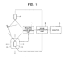
- FIG. 1 illustrates a configuration of an image display apparatus according to Embodiment 1 of the present invention.
- a fixed camera A is previously installed at a given place, and also, a moving camera B is located at a place different from the place of the fixed camera A.
- the moving camera B is mounted on a moving object U such as a vehicle and so on and is configured to be movable along with the moving object U.
- the moving object U is connected to a relative position calculation unit 1 that calculates a relative positional relationship of the moving camera B with respect to the fixed camera A.
- the relative position calculation unit 1, the fixed camera A, and the moving camera B are connected to an image composition unit 2.
- the image composition unit 2 is connected to a monitor 3.
- the moving object U includes a sensor (not shown) for obtaining positional information such as its own current position, orientation and so on, and a detection signal from the sensor is input to the relative position calculation unit 1.
- Step S1 an image is taken by the fixed camera A, and in the subsequent Step S2, an image is taken by the moving camera B. Furthermore, in Step S3, the relative positional relationship of the moving camera B with respect to the fixed camera A is calculated by the relative position calculation unit 1.
- the relative position calculation unit 1 can recognize the current position and orientation of the moving object U based on the input detection signal. Then, by comparing the current position and orientation of the moving object U with the given place at which the fixed camera A is installed, the relative position calculation unit 1 calculates the relative positional relationship of the moving camera B with respect to the fixed camera A.
- Step S4 the image composition unit 2 synthesizes the image taken by the fixed camera A and the image taken by the moving camera B into one image based on the relative positional relationship, thereby creating an overhead image which is a composite image viewed downward.
- Step S5 the overhead image is displayed on the monitor 3.
- any sensor can be employed as long as it can recognize the current position and orientation of the moving object U.
- the sensor include; a speed sensor or a distance amount sensor and a yaw-rate sensor; a GPS sensor and a yaw-rate sensor; and two GPS sensors mounted at different positions of the moving object U.
- the relative position calculation unit 1, the image composition unit 2 and the monitor 3 can be mounted on the moving object U.
- the fixed camera A and the image composition unit 2 may be connected by wire or by wireless.
- communication means has to be provided with both the fixed camera A and the image composition unit 2 respectively.
- the relative position calculation unit 1, the image composition unit 2 and the monitor 3 may be installed at a given place instead of being mounted on the moving object U.
- the sensor for obtaining the positional information of the moving object U is connected to the relative position calculation unit 1 by wire or by wireless, and also, the fixed camera A and the moving camera B are connected to the image composition unit 2 by wire or by wireless.
- the relative position calculation unit 1 may be mounted on the moving object U while the image composition unit 2 and the monitor 3 are installed at a given place. Otherwise, the relative position calculation unit 1 and the image composition unit 2 may be mounted on the moving object U while only the monitor 3 is installed at a given place.
- FIG. 3 illustrates a configuration of an image display apparatus according to Embodiment 2 of the present invention.
- the image display apparatus according to Embodiment 2 of the present invention is configured such that in the image display apparatus according to Embodiment 1 of the present invention illustrated in FIG. 1 , a mark M is previously set as a fixed target at a given fixed position instead of the sensor for obtaining the positional information provided with the moving object U and the relative position calculation unit 1 calculates the relative positional relationship between the fixed camera A and the moving camera B based on the image of the mark M taken by the moving camera B.
- the relative position calculation unit 1 includes image processing means 4, positional parameter calculating means 5 and relative position identifying means 6, which are connected to the moving camera B in the stated order. It is assumed that the mark M as the fixed target is fixed at a given place having a given positional relationship with respect to the fixed camera A and that the given positional relationship of the mark M with respect to the fixed camera A is previously recognized.
- the mark M as illustrated in FIG. 5 , for example, a figure having a square shape that is obtained by making four isosceles right triangles abut against one another may be used.
- the isosceles right triangles adjacent to each other are colored with different colors, and the mark M has five feature points C1 to C5, which are each intersections of a plurality of sides. As described above, as long as the positional relationship of the mark M with respect to the fixed camera A is previously recognized, the mark M may be placed outside the field of view of the fixed camera A.
- Embodiment 2 a composite image such as an overhead image and so on is displayed on the monitor 3 in accordance with Steps S1 to S5 of the flow chart illustrated in FIG. 2 .
- the calculation method for the relative positional relationship between the fixed camera A and the moving camera B in Step S3 is different from the calculation method according to Embodiment 1 of the present invention.
- Steps S6 to S8 illustrated in the flow chart of FIG. 6 the calculation of the relative positional relationship is performed as follows.
- Step S6 the image processing means 4 of the relative position calculation unit 1 extracts the five feature points C1 to C5 of the mark M from the image of the mark M taken by the moving camera B, and then detects and obtains two-dimensional coordinates of each of the feature points C1 to C5 on the image.
- Step S7 based on the two-dimensional coordinates of the respective feature points C1 to C5 detected by the image processing means 4, the positional parameter calculating means 5 calculates positional parameters including six parameters which are three-dimensional coordinates (x, y, z), a tilt angle (angle of depression), a pan angle (angle of direction), and a swing angle (angle of rotation).
- a point on the ground which moves in a downward direction perpendicular to the road surface from a given point on the moving object U, is set as an origin O
- a road surface coordinate system in which an x-axis and a y-axis are set in the horizontal direction and a z-axis is set in the vertical direction is assumed
- an image coordinate system in which an X-axis and a Y-axis are set on the image taken by the moving camera B is assumed.
- the positional parameters are determined by creating more relational expressions than the number (six) of the positional parameters (xm, ym, zm, Kn) to be calculated, it is possible to obtain the positional parameters (xm, ym, zm, Kn) with high accuracy.
- ten relational expressions are created by the five feature points C1 to C5 with respect to the six positional parameters (xm, ym, zm, Kn).
- the number of relational expressions merely has to be more than the number of the positional parameters (xm, ym, zm, Kn) to be calculated. Accordingly, if six relational expressions are created by at least three feature points, the six positional parameters (xm, ym, zm, Kn) can be calculated.
- the relative position identifying means 6 identifies the relative positional relationship of the moving camera B with respect to the fixed camera A. Specifically, based on the positional parameters calculated by the positional parameter calculating means 5, the relative positional relationship between the moving camera B and the mark M is identified. Furthermore, the relative positional relationship between the moving camera B and the fixed camera A is identified because the given positional relationship of the mark M with respect to the fixed camera A is previously recognized.
- the relative positional relationship between the fixed camera A and the moving camera B which has been calculated by the relative position calculation unit 1 in the aforementioned manner, is transmitted to the image composition unit 2.
- the image composition unit 2 combines, based on the relative positional relationship, the image taken by the fixed camera A and the image taken by the moving camera B into one image to create an overhead image, which is then displayed on the monitor 3.
- the positional parameters including the six parameters which are the three-dimensional coordinates (x, y, z) of the moving camera B with reference to the mark M, the tilt angle (angle of depression), the pan angle (angle of direction), and the swing angle (angle of rotation) are calculated. Accordingly, even if there is a step or a tilt between the floor surface on which the mark M is located and the road surface on which the moving object U is currently located, the relative positional relationship between the mark M and the moving camera B, and further, the relative positional relationship between the fixed camera A and the moving camera B are accurately identified, thereby enabling creation of an overhead image with high accuracy.
- the positional parameters including at least four parameters which are the three-dimensional coordinates (x, y, z) of the moving camera B with reference to the mark M and the pan angle (angle of direction), the relative positional relationship between the mark M and the moving camera B can be identified.
- four positional parameters can be obtained by creating four relational expressions by means of two-dimensional coordinates of at least two feature points of the mark M.
- two-dimensional coordinates of more feature points are used to calculate the four positional parameters for higher accuracy by a least-squares method or the like.
- the positional parameters including at least three parameters the two-dimensional coordinates (x, y) of the moving camera B with reference to the mark M and the pan angle (angle of direction), the relative positional relationship between the mark M and the moving camera B can be identified.
- three positional parameters can be obtained by creating four relational expressions by means of two-dimensional coordinates of at least two feature points of the mark M.
- two-dimensional coordinates of more feature points are used to calculate the three positional parameters for higher accuracy by a least-squares method or the like.
- FIG. 7 illustrates a configuration of an image display apparatus according to Embodiment 3 of the present invention.
- Embodiment 3 shows an example using the image display apparatus according to Embodiment 2 illustrated in FIG. 2 for parking support with the fixed camera A being installed in a parking space such as a garage and so on and the moving camera B being mounted on a vehicle to be parked in the parking space.
- a parking-space-side apparatus 11 is provided within a parking space S or in the vicinity thereof, and a vehicle-side apparatus 12 is mounted on the vehicle to be parked in the parking space S.
- the parking-space-side apparatus 11 includes the fixed camera A located at the back of the parking space S to take an image of the vicinity of an entrance of the parking space S, and the fixed camera A is connected to a communication unit 14 via an encoder 13.
- the encoder 13 is for compressing an image taken by the fixed camera A into a format suitable for wireless transmission.
- the communication unit 14 is mainly for transmitting image data compressed by the encoder 13 to the vehicle-side apparatus 12.
- a control unit 15 is connected to the fixed camera A and the communication unit 14.
- the parking-space-side apparatus 11 includes the mark M fixedly provided on the floor surface in the vicinity of the entrance of the parking space S.
- the vehicle-side apparatus 12 includes the moving camera B provided at the rear of the vehicle to take an image behind the vehicle. At the time of backing into the parking space S, an image of the mark M in the parking space S is taken by the moving camera B.
- the moving camera B is connected to the relative position calculation unit 1.
- the vehicle-side apparatus 12 includes a communication unit 16 for communicating with the communication unit 14 of the parking-space-side apparatus 11, and the communication unit 16 is connected to a decoder 17.
- the decoder 17 is for decoding the compressed image data received by the communication unit 16 from the parking-space-side apparatus 11.
- the decoder 17 is connected to the image composition unit 2.
- An image selection unit 18 is connected to both the image composition unit 2 and the moving camera B.
- the image selection unit 18 is connected to the monitor 3 located at the driver's seat of the vehicle.
- a control unit 19 is connected to the moving camera B, the relative position calculation unit 1, the communication unit 16, and the image selection unit 18. It is assumed that internal parameters (focal length, strain constant, and the like) of the moving camera B and the relative position and angle of the moving camera B with respect to the vehicle are previously known.
- the relative position calculation unit 1 of the vehicle-side apparatus 12 includes the image processing means 4, the positional parameter calculating means 5, and the relative position identifying means 6, which are connected in the stated order between the moving camera B and the image composition unit 2.
- Step S11 in a state where the vehicle is located in the vicinity of the parking space S so that the mark M is within the field of view of the moving camera B, the control unit 19 of the vehicle-side apparatus 12 operates the moving camera B to take an image of the mark M.
- the image taken by the moving camera B is input to the relative position calculation unit 1.
- the relative position calculation unit 1 calculates the relative positional relationship between the moving camera B and the fixed camera A according to the flow chart illustrated in FIG. 6 .
- the control unit 19 calculates a relative distance L of the moving camera B with respect to the fixed camera A.
- the relative distance L is compared with a given value Lth, and when the relative distance L is larger than the given value Lth, the control unit 19 causes the image selection unit 18 to select the image data from the moving camera B in Step S14. Consequently, as illustrated in FIG. 9 , an image of the area behind the vehicle, which has been taken by the moving camera B, is displayed on the screen of the monitor 3 located at the driver's seat.
- the control unit 19 transmits a request signal for the image data from the communication unit 16 to the parking-space-side apparatus 11 in Step S15.
- the control unit 15 operates the fixed camera A, thereby taking an image of the vicinity of the entrance of the parking space S in Step S16. Then, after the image data taken by the fixed camera A is compressed by the encoder 13 into a format suitable for wireless transmission, the compressed image data is transmitted from the communication unit 14 to the vehicle-side apparatus 12.
- Step 17 after the image data from the parking-space-side apparatus 11 is received by the communication unit 16 of the vehicle-side apparatus 12, the image data is decoded by the decoder 17, and then transmitted to the image composition unit 2.
- the image composition unit 2 synthesizes the image taken by the fixed camera A and the image taken by the moving camera B into one image to thereby create an overhead image based on the relative positional relationship between the fixed camera A and the moving camera B.
- the control unit 19 causes the image selection unit 18 to select the image data from the image composition unit 2. Consequently, as illustrated in FIG. 10 , the overhead image created by the image composition unit 2 is displayed on the screen of the monitor 3 located at the driver's seat.
- the given value Lth used in Step S13 may be set as follows. For example, after assuming a garage in which the both sides and the rear side of the parking space S are divided by walls or the like, the given value Lth is set with reference to a relative distance between the moving camera B and the fixed camera A when a part of a vehicle V during backward parking begins to enter the field of view of the fixed camera A. If the given value Lth is set in the aforementioned manner, the image of the area behind the vehicle taken by the moving camera B is displayed on the screen of the monitor 3 as illustrated in FIG. 9 when the vehicle V is not within the field of view of the fixed camera A, whereas after the vehicle V enters the field of view of the fixed camera A, as illustrated in FIG.
- the overhead image is displayed on the screen of the monitor 3. Accordingly, operation of the vehicle V can be performed while checking the overhead image displayed on the screen of the monitor 3, thereby making it easier to recognize the relative positional relationship between the vehicle V and the parking space S. As a result, it becomes possible to park the vehicle V into the parking space S with higher accuracy.
- FIG. 11 illustrates a configuration of an image display apparatus according to Embodiment 4 of the present invention.
- the image display apparatus according to Embodiment 4 of the present invention is configured such that in the image display apparatus according to Embodiment 2 of the present invention illustrated in FIG. 3 , a first moving camera B1 mounted on a first moving object U1 and a second moving camera B2 mounted on a second moving object U2 are arranged instead of the fixed camera A and the moving camera B and the moving cameras B1 and B2 are connected to a relative position calculation unit 21 instead of the relative position calculation unit 1 so as to take images of the same mark M by both the moving cameras B1 and B2.
- the relative position calculation unit 21 includes a first calculation unit 22 connected to the first moving camera B1, a second calculation unit 23 connected to the second moving camera B2, and a third calculation unit 24 connected to the first calculation unit 22 and the second calculation unit 23. Furthermore, the third calculation unit 24 is connected to the image composition unit 2.
- Step S21 in a state where the mark M is within the field of view of the first moving camera B1, an image is taken by the first moving camera B1.
- the first calculation unit 22 of the relative position calculation unit 21 extracts five feature points C1 to C5 of the mark M from the image of the mark M taken by the first moving camera B1, and then detects and obtains two-dimensional coordinates of the respective feature points C1 to C5 of the image.
- Step S23 based on the two-dimensional coordinates of the feature points C1 to C5, positional parameters including six parameters which are the three-dimensional coordinates (x, y, z) of the first moving camera B1 with reference to the mark M, the tilt angle (angle of depression), pan angle (angle of direction), and swing angle (angle of rotation) are calculated.
- Step S24 in a state where the mark M is within the field of view of the second moving camera B2, an image is taken by the second moving camera B2.
- the second calculation unit 23 of the relative position calculation unit 21 extracts the five feature points C1 to C5 of the mark M from the image of the mark M taken by the second moving camera B2, and then detects and obtains two-dimensional coordinates of the respective feature points C1 to C5 of the image.
- Step S26 based on the two-dimensional coordinates of the feature points C1 to C5, positional parameters including six parameters which are the three-dimensional coordinates (x, y, z) of the second moving camera B2 with reference to the mark M, the tilt angle (angle of depression), the pan angle (angle of direction), and the swing angle (angle of rotation) are calculated.
- the third calculation unit 24 of the relative position calculation unit 21 identifies the relative positional relationship between the first moving camera B1 and the second moving camera B2 based on the positional parameters of the first moving camera B1 and the second moving camera B2 calculated by the first calculation unit 22 and the second calculation unit 23 respectively.
- the relative positional relationship between the first moving camera B1 and the second moving camera B2 calculated by the relative position calculation unit 21 is transmitted to the image composition unit 2 in the aforementioned manner, and in Step S28, the image composition unit 2 synthesizes the image taken by the first moving camera B1 and the image taken by the second moving camera B2 into one image based on the relative positional relationship, thereby creating an overhead image.
- the overhead image is displayed on the monitor 3.
- FIG. 14 illustrates a configuration of an image display apparatus according to Embodiment 5 of the present invention.
- the image display apparatus according to Embodiment 5 of the present invention is configured such that in the image display apparatus according to Embodiment 4 of the present invention illustrated in FIG. 11 , instead of taking the images of the same mark M with the first moving camera B1 and the second moving camera B2, a plurality of marks M1 and M2 are arranged at different positions from each other and the first moving camera B1 and the second moving camera B2 each take an image of a mark different from each other.
- the relative positional relationship between the mark M1 and the mark M2 is previously known.
- the relative positional relationship between the mark M1 and the mark M2 may be stored in the relative position calculation unit 21.
- the marks M1 and M2 may be configured to record the respective positional information by means of a barcode or the like so that the positional information can be detected from the image taken by each camera. Still alternatively, the positional information of each of the marks M1 and M2 may be output from a wireless transmitter located in the vicinity of each mark, thereby allowing the positional information to be detected by receiving at the first moving object U1 and the second moving object U2.
- the first calculation unit 22 of the relative position calculation unit 21 calculates the positional parameters of the first moving camera B1 with reference to the mark M1 based on the image of the mark M1 taken by the first moving camera B1 and the second calculation unit 23 of the relative position calculation unit 21 calculates the positional parameters of the second moving camera B2 with reference to the mark M2 based on the image of the mark M2 taken by the second moving camera B2.
- the third calculation unit 24 of the relative position calculation unit 21 can identify the relative positional relationship between the first moving camera B1 and the second moving camera B2 based on the respective positional parameters calculated by the first calculation unit 22 and the second calculation unit 23 and the relative positional relationship between the marks M1 and M2.
- the image composition unit 2 can synthesize the image taken by the first moving camera B1 and the image taken by the second moving camera B2 into one image based on the relative positional relationship, thereby creating an overhead image which is then displayed on the monitor 3.
- the marks photographed by each of the moving cameras B1 and B2 is not specified as one of the marks M1 and M2, or in a case where both the marks M1 and M2 are photographed at the same time, in order to determine whether the photographed mark is the mark M1 or the mark M2, it is desirable that the marks M1 and M2 be different from each other in shape, color, or the like.
- the composite image created by the image composition unit 2 is not limited to the overhead image, and hence the image composition unit 2 can create an image viewed from an arbitrary virtual viewpoint P different from the viewpoint of each camera. Furthermore, the composite image is not necessarily limited to the image viewed from the virtual viewpoint P different from the viewpoint of each camera, and hence the image composition unit 2 can create an image viewed from the viewpoint of any one of a plurality of cameras.
- the image composition unit 2 may convert the image taken by the fixed camera A in the parking space side into an image viewed from the viewpoint of the moving camera B mounted on the vehicle, and synthesize the converted image with the image taken by the moving camera B, whereby it is possible to obtain a composite image that is added with a see-through area of such a blind spot within the parking space S as illustrated in FIG. 9 , which is hidden from view by the wall in the image taken by the moving camera B mounted on the vehicle. In other cases, it is possible to obtain a composite image that is added with a blind spot area that is outside the shooting range in the image taken by the moving camera B mounted on the vehicle alone.
- the images taken by one fixed camera A and one moving camera B, or the images taken by two moving cameras B1 and B2 are synthesized.
- the moving objects U, U1, and U2 are not limited to moving equipment such as a vehicle and so on but, for example, may be a person walking with a camera.
- the mark used in Embodiments 2 to 5 of the present invention has a square-like shape obtained by making four isosceles right triangles abut to one another, but is not limited to such marks, as various kinds of marks may be used. However, it is desirable that the mark have a specific shape, color, or the like that makes it easier to identify against other shapes existing in the natural world, whereby the presence of the mark is easily recognized through image detection by the image processing means 4. Moreover, it is desirable that the feature points within the mark are easily detected.
- the mark is sufficiently large for the relative positional relationship between the camera and the mark to be calculated with high accuracy based on the two-dimensional coordinates of the detected feature points and also that the mark is placed at a place where the mark cam be easily detected by the camera.
- the mark may be placed in the vicinity of where the camera is located, such as a floor surface, a wall surface, a ceiling surface and so on.
Abstract
Images are taken by a fixed camera (A) and a moving camera (B), and a relative position calculation unit (1) recognizes a current position and orientation of the moving object (U) based on a detection signal that is input from a sensor for obtaining positional information of a moving object (U) and calculates a relative positional relationship of the moving camera (B) with respect to the fixed camera (A) by comparing the current position and orientation of the moving object (U) with a given position at which the fixed camera (A) is installed. Based on the relative positional relationship, the image taken by the fixed camera (A) and the image taken by the moving camera (B) are synthesized into one image by an image composition unit (2), and a composite image viewed from a virtual viewpoint (P) is displayed on a monitor (3).
Description
- The present invention relates to an image display apparatus and an image display method, and more particularly, to an apparatus and method for synthesizing images taken by a plurality of cameras into one image and displaying the image.
-
JP 09-114979 A - However, with respect to the system disclosed in
JP 09-114979 A
Recently, with the aim of improving the safety and operability of driving, a system has been used in which some cameras for taking the images of the rear part and the side part of a vehicle are mounted on the vehicle and the images taken by the cameras are displayed on a monitor located at the driver's seat at the time of, for example, backing the vehicle up.
By utilizing the aforementioned cameras that are mounted on a vehicle and installing only one fixed camera installed in the parking space side so as to be able to generate an overhead image, the driving operation at the time of parking can be easily and cheaply made more comfortable. However, since the movement of the vehicle changes the relative positional relationship between the cameras mounted on the vehicle and the fixed camera installed in the parking space side, it is difficult for the system disclosed inJP 09-114979 A - The present invention has been made to solve the above-mentioned problem in the conventional art, and therefore has an object of providing an image display method that can display an image viewed from a given viewpoint even if a plurality of cameras having a variable relative positional relationship between each other are used.
- The present image display apparatus comprises: a plurality of cameras for which the relative positional relationship changes; a relative position calculation unit for calculating the relative positional relationship of the plurality of cameras; an image composition unit for creating an image viewed from a given viewpoint by synthesizing images taken by the plurality of cameras based on the relative positional relationship calculated by the relative position calculation unit; and a monitor for displaying the image created by the image composition unit.
- The present image display method comprises: calculating a relative positional relationship of a plurality of cameras, for which the relative positional relationship changes; creating an image viewed from a given viewpoint by synthesizing images taken by the plurality of cameras based on the calculated relative positional relationship; and displaying the created image viewed from the given viewpoint.
- According to the present invention, because the relative positional relationship of the plurality of cameras is calculated by the relative position calculation unit and the images taken by the plurality of cameras are synthesized by the image composition unit based on the relative positional relationship, an image viewed from a given viewpoint can be displayed even if a plurality of cameras having a variable relative positional relationship between each other are used.
-
-
FIG. 1 is a block diagram illustrating a configuration of an image display apparatus according toEmbodiment 1 of the present invention; -
FIG. 2 is a flow chart illustrating an operation according toEmbodiment 1 of the present invention; -
FIG. 3 is a block diagram illustrating a configuration of an image display apparatus according toEmbodiment 2 of the present invention; -
FIG. 4 is a block diagram illustrating a configuration of a relative position calculation unit according toEmbodiment 2 of the present invention; -
FIG. 5 is a diagram illustrating a mark used inEmbodiment 2 of the present invention; -
FIG. 6 is a flow chart illustrating an operation of a step for calculating a relative positional relationship between a moving camera and a fixed camera according toEmbodiment 2 of the present invention; -
FIG. 7 is a block diagram illustrating a configuration of an image display apparatus according toEmbodiment 3 of the present invention; -
FIG. 8 is a flow chart illustrating an operation according toEmbodiment 3 of the present invention; -
FIG. 9 is a diagram illustrating a screen of a monitor according toEmbodiment 3 of the present invention; -
FIG. 10 is a diagram illustrating a screen of the monitor according toEmbodiment 3 of the present invention; -
FIG. 11 is a block diagram illustrating a configuration of an image display apparatus according toEmbodiment 4 of the present invention; -
FIG. 12 is a block diagram illustrating a configuration of a relative position calculation unit according toEmbodiment 4 of the present invention; -
FIG. 13 is a flow chart illustrating an operation according toEmbodiment 4 of the present invention; and -
FIG. 14 is a block diagram illustrating a configuration of an image display apparatus according toEmbodiment 4 of the present invention. - Hereinafter, Embodiments according to the present invention are described with reference to the accompanying drawings.
-
FIG. 1 illustrates a configuration of an image display apparatus according toEmbodiment 1 of the present invention. A fixed camera A is previously installed at a given place, and also, a moving camera B is located at a place different from the place of the fixed camera A. The moving camera B is mounted on a moving object U such as a vehicle and so on and is configured to be movable along with the moving object U.
The moving object U is connected to a relativeposition calculation unit 1 that calculates a relative positional relationship of the moving camera B with respect to the fixed camera A. The relativeposition calculation unit 1, the fixed camera A, and the moving camera B are connected to animage composition unit 2. Furthermore, theimage composition unit 2 is connected to amonitor 3.
Furthermore, the moving object U includes a sensor (not shown) for obtaining positional information such as its own current position, orientation and so on, and a detection signal from the sensor is input to the relativeposition calculation unit 1. - Next, referring to the flow chart of
FIG. 2 , an operation according toEmbodiment 1 of the present invention is described. First, in Step S1, an image is taken by the fixed camera A, and in the subsequent Step S2, an image is taken by the moving camera B.
Furthermore, in Step S3, the relative positional relationship of the moving camera B with respect to the fixed camera A is calculated by the relativeposition calculation unit 1. At this point, because the detection signal from the sensor for obtaining the positional information of the moving object U has been input to the relativeposition calculation unit 1, the relativeposition calculation unit 1 can recognize the current position and orientation of the moving object U based on the input detection signal. Then, by comparing the current position and orientation of the moving object U with the given place at which the fixed camera A is installed, the relativeposition calculation unit 1 calculates the relative positional relationship of the moving camera B with respect to the fixed camera A. - After the relative positional relationship between the fixed camera A and the moving camera B is calculated as described above, in Step S4, the
image composition unit 2 synthesizes the image taken by the fixed camera A and the image taken by the moving camera B into one image based on the relative positional relationship, thereby creating an overhead image which is a composite image viewed downward.
Next, in Step S5, the overhead image is displayed on themonitor 3. - It should be noted that, as an example of synthesizing the image taken by the fixed camera A and the image taken by the moving camera B and creating the overhead image, there can be mentioned
JP 03-099952 A
Furthermore, as the sensor for obtaining the positional information of the moving object U, any sensor can be employed as long as it can recognize the current position and orientation of the moving object U. Examples of the sensor include; a speed sensor or a distance amount sensor and a yaw-rate sensor; a GPS sensor and a yaw-rate sensor; and two GPS sensors mounted at different positions of the moving object U. - The relative
position calculation unit 1, theimage composition unit 2 and themonitor 3 can be mounted on the moving object U. In this case, the fixed camera A and theimage composition unit 2 may be connected by wire or by wireless. When the fixed camera A and theimage composition unit 2 are connected by wireless, communication means has to be provided with both the fixed camera A and theimage composition unit 2 respectively.
Furthermore, the relativeposition calculation unit 1, theimage composition unit 2 and themonitor 3 may be installed at a given place instead of being mounted on the moving object U. In this case, the sensor for obtaining the positional information of the moving object U is connected to the relativeposition calculation unit 1 by wire or by wireless, and also, the fixed camera A and the moving camera B are connected to theimage composition unit 2 by wire or by wireless.
Further, only the relativeposition calculation unit 1 may be mounted on the moving object U while theimage composition unit 2 and themonitor 3 are installed at a given place. Otherwise, the relativeposition calculation unit 1 and theimage composition unit 2 may be mounted on the moving object U while only themonitor 3 is installed at a given place. -
FIG. 3 illustrates a configuration of an image display apparatus according toEmbodiment 2 of the present invention. The image display apparatus according toEmbodiment 2 of the present invention is configured such that in the image display apparatus according toEmbodiment 1 of the present invention illustrated inFIG. 1 , a mark M is previously set as a fixed target at a given fixed position instead of the sensor for obtaining the positional information provided with the moving object U and the relativeposition calculation unit 1 calculates the relative positional relationship between the fixed camera A and the moving camera B based on the image of the mark M taken by the moving camera B. - As illustrated in
FIG. 4 , the relativeposition calculation unit 1 includes image processing means 4, positional parameter calculating means 5 and relative position identifying means 6, which are connected to the moving camera B in the stated order.
It is assumed that the mark M as the fixed target is fixed at a given place having a given positional relationship with respect to the fixed camera A and that the given positional relationship of the mark M with respect to the fixed camera A is previously recognized. For the mark M, as illustrated inFIG. 5 , for example, a figure having a square shape that is obtained by making four isosceles right triangles abut against one another may be used. The isosceles right triangles adjacent to each other are colored with different colors, and the mark M has five feature points C1 to C5, which are each intersections of a plurality of sides.
As described above, as long as the positional relationship of the mark M with respect to the fixed camera A is previously recognized, the mark M may be placed outside the field of view of the fixed camera A. - Similarly, in
Embodiment 2, a composite image such as an overhead image and so on is displayed on themonitor 3 in accordance with Steps S1 to S5 of the flow chart illustrated inFIG. 2 . However, the calculation method for the relative positional relationship between the fixed camera A and the moving camera B in Step S3 is different from the calculation method according toEmbodiment 1 of the present invention. In accordance with Steps S6 to S8 illustrated in the flow chart ofFIG. 6 , the calculation of the relative positional relationship is performed as follows. - At first, in Step S6, the image processing means 4 of the relative
position calculation unit 1 extracts the five feature points C1 to C5 of the mark M from the image of the mark M taken by the moving camera B, and then detects and obtains two-dimensional coordinates of each of the feature points C1 to C5 on the image.
Next, in Step S7, based on the two-dimensional coordinates of the respective feature points C1 to C5 detected by the image processing means 4, the positional parameter calculating means 5 calculates positional parameters including six parameters which are three-dimensional coordinates (x, y, z), a tilt angle (angle of depression), a pan angle (angle of direction), and a swing angle (angle of rotation). - Here, the calculation method for the positional parameters by the positional parameter calculating means 5 is described.
First, a point on the ground, which moves in a downward direction perpendicular to the road surface from a given point on the moving object U, is set as an origin O, a road surface coordinate system in which an x-axis and a y-axis are set in the horizontal direction and a z-axis is set in the vertical direction is assumed, and an image coordinate system in which an X-axis and a Y-axis are set on the image taken by the moving camera B is assumed.
Coordinate values Xm and Ym (m=1 to 5) of the feature points C1 to C5 of the mark M in the image coordinate system are expressed, with the six positional parameters of the respective feature points C1 to C5 of the mark M in the road surface coordinate system, that is, coordinate values xm, ym, and zm, angle parameters Kn (n=1 to 3) of the tilt angle (angle of depression), the pan angle (angle of direction), and the swing angle (angle of rotation), by using functions F and G as follows:

where DXm is the deviation between the X coordinate of each of the feature points C1 to C5 calculated by means of the functions F and G and the coordinate value Xm of each of the feature points C1 to C5 detected by the image processing means 4 and where DYm is the deviation between the Y coordinate of each of the feature points C1 to C5 calculated by means of the functions F and G and the coordinate value Ym of each of the feature points C1 to C5 detected by the image processing means 4. - Specifically, by expressing the X-coordinate and the Y-coordinate of each of the five feature points C1 to C5, a total of ten relational expressions are created with respect to the six positional parameters (xm, ym, zm, Kn).
Here, positional parameters (xm, ym, zm, Kn) which minimize the sum of squares S of the deviations DXm and DYm, which is expressed as follows:
- Because the positional parameters are determined by creating more relational expressions than the number (six) of the positional parameters (xm, ym, zm, Kn) to be calculated, it is possible to obtain the positional parameters (xm, ym, zm, Kn) with high accuracy.
InEmbodiment 2 of the present invention, ten relational expressions are created by the five feature points C1 to C5 with respect to the six positional parameters (xm, ym, zm, Kn). However, the number of relational expressions merely has to be more than the number of the positional parameters (xm, ym, zm, Kn) to be calculated. Accordingly, if six relational expressions are created by at least three feature points, the six positional parameters (xm, ym, zm, Kn) can be calculated. - By using the positional parameters of the moving camera B calculated in the aforementioned manner, in Step S8, the relative position identifying means 6 identifies the relative positional relationship of the moving camera B with respect to the fixed camera A. Specifically, based on the positional parameters calculated by the positional parameter calculating means 5, the relative positional relationship between the moving camera B and the mark M is identified. Furthermore, the relative positional relationship between the moving camera B and the fixed camera A is identified because the given positional relationship of the mark M with respect to the fixed camera A is previously recognized.
- The relative positional relationship between the fixed camera A and the moving camera B, which has been calculated by the relative
position calculation unit 1 in the aforementioned manner, is transmitted to theimage composition unit 2. Theimage composition unit 2 combines, based on the relative positional relationship, the image taken by the fixed camera A and the image taken by the moving camera B into one image to create an overhead image, which is then displayed on themonitor 3. - In
Embodiment 2 of the present invention, the positional parameters including the six parameters which are the three-dimensional coordinates (x, y, z) of the moving camera B with reference to the mark M, the tilt angle (angle of depression), the pan angle (angle of direction), and the swing angle (angle of rotation) are calculated. Accordingly, even if there is a step or a tilt between the floor surface on which the mark M is located and the road surface on which the moving object U is currently located, the relative positional relationship between the mark M and the moving camera B, and further, the relative positional relationship between the fixed camera A and the moving camera B are accurately identified, thereby enabling creation of an overhead image with high accuracy. - However, when there is no tilt between the floor surface on which the mark M is located and the road surface on which the moving object U is currently located, by calculating the positional parameters including at least four parameters which are the three-dimensional coordinates (x, y, z) of the moving camera B with reference to the mark M and the pan angle (angle of direction), the relative positional relationship between the mark M and the moving camera B can be identified. In this case, four positional parameters can be obtained by creating four relational expressions by means of two-dimensional coordinates of at least two feature points of the mark M. However, it is desirable that two-dimensional coordinates of more feature points are used to calculate the four positional parameters for higher accuracy by a least-squares method or the like.
- Furthermore, in a case where the mark M and the moving object U are on the same plane and there is no step or tilt between the floor surface on which the mark M is located and the road surface on which the moving object U is currently located, by calculating the positional parameters including at least three parameters the two-dimensional coordinates (x, y) of the moving camera B with reference to the mark M and the pan angle (angle of direction), the relative positional relationship between the mark M and the moving camera B can be identified. Similarly, in this case, three positional parameters can be obtained by creating four relational expressions by means of two-dimensional coordinates of at least two feature points of the mark M. However, it is desirable that two-dimensional coordinates of more feature points are used to calculate the three positional parameters for higher accuracy by a least-squares method or the like.
-
FIG. 7 illustrates a configuration of an image display apparatus according toEmbodiment 3 of the present invention.Embodiment 3 shows an example using the image display apparatus according toEmbodiment 2 illustrated inFIG. 2 for parking support with the fixed camera A being installed in a parking space such as a garage and so on and the moving camera B being mounted on a vehicle to be parked in the parking space.
A parking-space-side apparatus 11 is provided within a parking space S or in the vicinity thereof, and a vehicle-side apparatus 12 is mounted on the vehicle to be parked in the parking space S. - The parking-space-
side apparatus 11 includes the fixed camera A located at the back of the parking space S to take an image of the vicinity of an entrance of the parking space S, and the fixed camera A is connected to acommunication unit 14 via anencoder 13. Theencoder 13 is for compressing an image taken by the fixed camera A into a format suitable for wireless transmission. Thecommunication unit 14 is mainly for transmitting image data compressed by theencoder 13 to the vehicle-side apparatus 12. Acontrol unit 15 is connected to the fixed camera A and thecommunication unit 14. Furthermore, the parking-space-side apparatus 11 includes the mark M fixedly provided on the floor surface in the vicinity of the entrance of the parking space S.
It is assumed that internal parameters (focal length, strain constant, and the like) and external parameters (relative position, angle, and the like, with respect to the parking space S) of the fixed camera A are previously known. Similarly, it is assumed that the relative position of the mark M with respect to the fixed camera A is known. - On the other hand, the vehicle-
side apparatus 12 includes the moving camera B provided at the rear of the vehicle to take an image behind the vehicle. At the time of backing into the parking space S, an image of the mark M in the parking space S is taken by the moving camera B. The moving camera B is connected to the relativeposition calculation unit 1. Furthermore, the vehicle-side apparatus 12 includes acommunication unit 16 for communicating with thecommunication unit 14 of the parking-space-side apparatus 11, and thecommunication unit 16 is connected to adecoder 17. Thedecoder 17 is for decoding the compressed image data received by thecommunication unit 16 from the parking-space-side apparatus 11. - The
decoder 17 is connected to theimage composition unit 2. Animage selection unit 18 is connected to both theimage composition unit 2 and the moving camera B. Theimage selection unit 18 is connected to themonitor 3 located at the driver's seat of the vehicle.
Furthermore, acontrol unit 19 is connected to the moving camera B, the relativeposition calculation unit 1, thecommunication unit 16, and theimage selection unit 18.
It is assumed that internal parameters (focal length, strain constant, and the like) of the moving camera B and the relative position and angle of the moving camera B with respect to the vehicle are previously known.
As illustrated inFIG. 4 , the relativeposition calculation unit 1 of the vehicle-side apparatus 12 includes the image processing means 4, the positional parameter calculating means 5, and the relative position identifying means 6, which are connected in the stated order between the moving camera B and theimage composition unit 2. - Next, with reference to the flow chart of
FIG. 8 , an operation according toEmbodiment 3 is described.
First, in Step S11, in a state where the vehicle is located in the vicinity of the parking space S so that the mark M is within the field of view of the moving camera B, thecontrol unit 19 of the vehicle-side apparatus 12 operates the moving camera B to take an image of the mark M.
The image taken by the moving camera B is input to the relativeposition calculation unit 1. In the subsequent Step S12, the relativeposition calculation unit 1 calculates the relative positional relationship between the moving camera B and the fixed camera A according to the flow chart illustrated inFIG. 6 . - Accordingly, based on the relative positional relationship calculated by the relative
position calculation unit 1, thecontrol unit 19 calculates a relative distance L of the moving camera B with respect to the fixed camera A. In Step S13, the relative distance L is compared with a given value Lth, and when the relative distance L is larger than the given value Lth, thecontrol unit 19 causes theimage selection unit 18 to select the image data from the moving camera B in Step S14. Consequently, as illustrated inFIG. 9 , an image of the area behind the vehicle, which has been taken by the moving camera B, is displayed on the screen of themonitor 3 located at the driver's seat. - On the other hand, when the relative distance L of the moving camera B with respect to the fixed camera A is less than or equal to the given value Lth, the
control unit 19 transmits a request signal for the image data from thecommunication unit 16 to the parking-space-side apparatus 11 in Step S15.
In the parking-space-side apparatus 11, when thecommunication unit 14 receives the request signal for the image data from the vehicle-side apparatus 12, thecontrol unit 15 operates the fixed camera A, thereby taking an image of the vicinity of the entrance of the parking space S in Step S16. Then, after the image data taken by the fixed camera A is compressed by theencoder 13 into a format suitable for wireless transmission, the compressed image data is transmitted from thecommunication unit 14 to the vehicle-side apparatus 12. - In
Step 17, after the image data from the parking-space-side apparatus 11 is received by thecommunication unit 16 of the vehicle-side apparatus 12, the image data is decoded by thedecoder 17, and then transmitted to theimage composition unit 2.
In Step S18, theimage composition unit 2 synthesizes the image taken by the fixed camera A and the image taken by the moving camera B into one image to thereby create an overhead image based on the relative positional relationship between the fixed camera A and the moving camera B.
In Step S19, because the relative distance L of the moving camera B with respect to the fixed camera A is less than or equal to the given value Lth, thecontrol unit 19 causes theimage selection unit 18 to select the image data from theimage composition unit 2. Consequently, as illustrated inFIG. 10 , the overhead image created by theimage composition unit 2 is displayed on the screen of themonitor 3 located at the driver's seat. - It should be noted that the given value Lth used in Step S13 may be set as follows. For example, after assuming a garage in which the both sides and the rear side of the parking space S are divided by walls or the like, the given value Lth is set with reference to a relative distance between the moving camera B and the fixed camera A when a part of a vehicle V during backward parking begins to enter the field of view of the fixed camera A.
If the given value Lth is set in the aforementioned manner, the image of the area behind the vehicle taken by the moving camera B is displayed on the screen of themonitor 3 as illustrated inFIG. 9 when the vehicle V is not within the field of view of the fixed camera A, whereas after the vehicle V enters the field of view of the fixed camera A, as illustrated inFIG. 10 , the overhead image is displayed on the screen of themonitor 3. Accordingly, operation of the vehicle V can be performed while checking the overhead image displayed on the screen of themonitor 3, thereby making it easier to recognize the relative positional relationship between the vehicle V and the parking space S. As a result, it becomes possible to park the vehicle V into the parking space S with higher accuracy. -
FIG. 11 illustrates a configuration of an image display apparatus according toEmbodiment 4 of the present invention. The image display apparatus according toEmbodiment 4 of the present invention is configured such that in the image display apparatus according toEmbodiment 2 of the present invention illustrated inFIG. 3 , a first moving camera B1 mounted on a first moving object U1 and a second moving camera B2 mounted on a second moving object U2 are arranged instead of the fixed camera A and the moving camera B and the moving cameras B1 and B2 are connected to a relativeposition calculation unit 21 instead of the relativeposition calculation unit 1 so as to take images of the same mark M by both the moving cameras B1 and B2. - As illustrated in
FIG. 12 , the relativeposition calculation unit 21 includes afirst calculation unit 22 connected to the first moving camera B1, asecond calculation unit 23 connected to the second moving camera B2, and athird calculation unit 24 connected to thefirst calculation unit 22 and thesecond calculation unit 23. Furthermore, thethird calculation unit 24 is connected to theimage composition unit 2. - Next, with reference to the flow chart of
FIG. 13 , an operation according toEmbodiment 4 of the present invention is described.
At first, in Step S21, in a state where the mark M is within the field of view of the first moving camera B1, an image is taken by the first moving camera B1. In the subsequent Step S22, thefirst calculation unit 22 of the relativeposition calculation unit 21 extracts five feature points C1 to C5 of the mark M from the image of the mark M taken by the first moving camera B1, and then detects and obtains two-dimensional coordinates of the respective feature points C1 to C5 of the image. Afterwards, in Step S23, based on the two-dimensional coordinates of the feature points C1 to C5, positional parameters including six parameters which are the three-dimensional coordinates (x, y, z) of the first moving camera B1 with reference to the mark M, the tilt angle (angle of depression), pan angle (angle of direction), and swing angle (angle of rotation) are calculated. - Next, in Step S24, in a state where the mark M is within the field of view of the second moving camera B2, an image is taken by the second moving camera B2. In the subsequent Step S25, the
second calculation unit 23 of the relativeposition calculation unit 21 extracts the five feature points C1 to C5 of the mark M from the image of the mark M taken by the second moving camera B2, and then detects and obtains two-dimensional coordinates of the respective feature points C1 to C5 of the image. Afterwards, in Step S26, based on the two-dimensional coordinates of the feature points C1 to C5, positional parameters including six parameters which are the three-dimensional coordinates (x, y, z) of the second moving camera B2 with reference to the mark M, the tilt angle (angle of depression), the pan angle (angle of direction), and the swing angle (angle of rotation) are calculated. - Furthermore, in Step S27, the
third calculation unit 24 of the relativeposition calculation unit 21 identifies the relative positional relationship between the first moving camera B1 and the second moving camera B2 based on the positional parameters of the first moving camera B1 and the second moving camera B2 calculated by thefirst calculation unit 22 and thesecond calculation unit 23 respectively.
The relative positional relationship between the first moving camera B1 and the second moving camera B2 calculated by the relativeposition calculation unit 21 is transmitted to theimage composition unit 2 in the aforementioned manner, and in Step S28, theimage composition unit 2 synthesizes the image taken by the first moving camera B1 and the image taken by the second moving camera B2 into one image based on the relative positional relationship, thereby creating an overhead image. In Step S29, the overhead image is displayed on themonitor 3. -
FIG. 14 illustrates a configuration of an image display apparatus according toEmbodiment 5 of the present invention. The image display apparatus according toEmbodiment 5 of the present invention is configured such that in the image display apparatus according toEmbodiment 4 of the present invention illustrated inFIG. 11 , instead of taking the images of the same mark M with the first moving camera B1 and the second moving camera B2, a plurality of marks M1 and M2 are arranged at different positions from each other and the first moving camera B1 and the second moving camera B2 each take an image of a mark different from each other.
It is assumed that the relative positional relationship between the mark M1 and the mark M2 is previously known. For example, the relative positional relationship between the mark M1 and the mark M2 may be stored in the relativeposition calculation unit 21. Alternatively, the marks M1 and M2 may be configured to record the respective positional information by means of a barcode or the like so that the positional information can be detected from the image taken by each camera. Still alternatively, the positional information of each of the marks M1 and M2 may be output from a wireless transmitter located in the vicinity of each mark, thereby allowing the positional information to be detected by receiving at the first moving object U1 and the second moving object U2. - In the case where the first moving camera B1 takes an image of the mark M1 and the second moving camera B2 takes an image of the mark M2, the
first calculation unit 22 of the relativeposition calculation unit 21 calculates the positional parameters of the first moving camera B1 with reference to the mark M1 based on the image of the mark M1 taken by the first moving camera B1 and thesecond calculation unit 23 of the relativeposition calculation unit 21 calculates the positional parameters of the second moving camera B2 with reference to the mark M2 based on the image of the mark M2 taken by the second moving camera B2.
Here, because the relative positional relationship between the mark M1 and the mark M2 is previously recognized, thethird calculation unit 24 of the relativeposition calculation unit 21 can identify the relative positional relationship between the first moving camera B1 and the second moving camera B2 based on the respective positional parameters calculated by thefirst calculation unit 22 and thesecond calculation unit 23 and the relative positional relationship between the marks M1 and M2.
As a result, theimage composition unit 2 can synthesize the image taken by the first moving camera B1 and the image taken by the second moving camera B2 into one image based on the relative positional relationship, thereby creating an overhead image which is then displayed on themonitor 3. - In a case where the mark photographed by each of the moving cameras B1 and B2 is not specified as one of the marks M1 and M2, or in a case where both the marks M1 and M2 are photographed at the same time, in order to determine whether the photographed mark is the mark M1 or the mark M2, it is desirable that the marks M1 and M2 be different from each other in shape, color, or the like.
- In each of Embodiments described above, the composite image created by the
image composition unit 2 is not limited to the overhead image, and hence theimage composition unit 2 can create an image viewed from an arbitrary virtual viewpoint P different from the viewpoint of each camera. Furthermore, the composite image is not necessarily limited to the image viewed from the virtual viewpoint P different from the viewpoint of each camera, and hence theimage composition unit 2 can create an image viewed from the viewpoint of any one of a plurality of cameras. For example, in theaforementioned Embodiment 3 of the present invention, theimage composition unit 2 may convert the image taken by the fixed camera A in the parking space side into an image viewed from the viewpoint of the moving camera B mounted on the vehicle, and synthesize the converted image with the image taken by the moving camera B, whereby it is possible to obtain a composite image that is added with a see-through area of such a blind spot within the parking space S as illustrated inFIG. 9 , which is hidden from view by the wall in the image taken by the moving camera B mounted on the vehicle. In other cases, it is possible to obtain a composite image that is added with a blind spot area that is outside the shooting range in the image taken by the moving camera B mounted on the vehicle alone. - In the above-mentioned Embodiments of the present invention, the images taken by one fixed camera A and one moving camera B, or the images taken by two moving cameras B1 and B2 are synthesized. However, it is also possible to create an image viewed from the arbitrary virtual viewpoint P by synthesizing images taken by more than three cameras of which the relative positional relationships change.
Furthermore, the moving objects U, U1, and U2 are not limited to moving equipment such as a vehicle and so on but, for example, may be a person walking with a camera. - The mark used in
Embodiments 2 to 5 of the present invention has a square-like shape obtained by making four isosceles right triangles abut to one another, but is not limited to such marks, as various kinds of marks may be used. However, it is desirable that the mark have a specific shape, color, or the like that makes it easier to identify against other shapes existing in the natural world, whereby the presence of the mark is easily recognized through image detection by the image processing means 4. Moreover, it is desirable that the feature points within the mark are easily detected.
Furthermore, it is desirable that the mark is sufficiently large for the relative positional relationship between the camera and the mark to be calculated with high accuracy based on the two-dimensional coordinates of the detected feature points and also that the mark is placed at a place where the mark cam be easily detected by the camera. Specifically, the mark may be placed in the vicinity of where the camera is located, such as a floor surface, a wall surface, a ceiling surface and so on.
Claims (9)
- An image display apparatus comprising:a plurality of cameras of which a relative positional relationship changes;a relative position calculation unit for calculating the relative positional relationship of the plurality of cameras;an image composition unit for creating an image viewed from a given viewpoint by synthesizing images taken by the plurality of cameras based on the relative positional relationship calculated by the relative position calculation unit; anda monitor for displaying the image created by the image composition unit.
- An image display apparatus according to Claim 1, wherein the plurality of cameras comprise at least one moving camera and at least one fixed camera.
- An image display apparatus according to Claim 1, wherein each of the plurality of cameras is a moving camera.
- An image display apparatus according to Claim 2 or 3, further comprising a fixed target including at least one feature point and previously placed at a given fixed position,
wherein the relative position calculation unit:calculates a positional parameter of the moving camera with reference to the fixed target based on an image of the fixed target taken by the moving camera; andcalculates the relative positional relationship of the moving camera with respect to the other cameras based on the calculated positional parameter. - An image display apparatus according to Claim 4, wherein the fixed target is a mark with a given shape.
- An image display apparatus according to any of Claims 1 to 5, wherein the image composition unit creates an image viewed from a virtual viewpoint different from viewpoints of the plurality of cameras as an image viewed from the given viewpoint.
- An image display apparatus according to Claim 6, wherein the image composition unit creates an overhead image as an image viewed from the given viewpoint.
- An image display apparatus according to any of Claims 1 to 5, wherein the image composition unit creates an image obtained by viewing from a viewpoint of any of the plurality of cameras and adding an image to a blind spot area as an image viewed from the given viewpoint.
- An image display method comprising:calculating a relative positional relationship of a plurality of cameras, for which the relative positional relationship changes;creating an image viewed from a given viewpoint by synthesizing images taken by the plurality of cameras based on the calculated relative positional relationship; anddisplaying the created image viewed from the given viewpoint.
Applications Claiming Priority (2)
| Application Number | Priority Date | Filing Date | Title |
|---|---|---|---|
| JP2007272654A JP2009101718A (en) | 2007-10-19 | 2007-10-19 | Image display device and image display method |
| PCT/JP2008/068152 WO2009051028A1 (en) | 2007-10-19 | 2008-10-06 | Video display device and video display method |
Publications (2)
| Publication Number | Publication Date |
|---|---|
| EP2200312A1 true EP2200312A1 (en) | 2010-06-23 |
| EP2200312A4 EP2200312A4 (en) | 2010-10-20 |
Family
ID=40567297
Family Applications (1)
| Application Number | Title | Priority Date | Filing Date |
|---|---|---|---|
| EP08839973A Withdrawn EP2200312A4 (en) | 2007-10-19 | 2008-10-06 | Video display device and video display method |
Country Status (7)
| Country | Link |
|---|---|
| US (1) | US20100201810A1 (en) |
| EP (1) | EP2200312A4 (en) |
| JP (1) | JP2009101718A (en) |
| KR (1) | KR20100053694A (en) |
| CN (1) | CN101828394A (en) |
| TW (1) | TW200926067A (en) |
| WO (1) | WO2009051028A1 (en) |
Cited By (2)
| Publication number | Priority date | Publication date | Assignee | Title |
|---|---|---|---|---|
| FR2985350A1 (en) * | 2012-01-04 | 2013-07-05 | Peugeot Citroen Automobiles Sa | METHOD FOR PROCESSING IMAGE OF A CAMERA ONBOARD ON A VEHICLE AND CORRESPONDING PROCESSING DEVICE |
| US10556586B2 (en) | 2015-03-03 | 2020-02-11 | Volvo Truck Corporation | Vehicle assistance system |
Families Citing this family (16)
| Publication number | Priority date | Publication date | Assignee | Title |
|---|---|---|---|---|
| JP2011086111A (en) * | 2009-10-15 | 2011-04-28 | Mitsubishi Electric Corp | Imaging apparatus calibration method and image synthesis device |
| JP2011237532A (en) * | 2010-05-07 | 2011-11-24 | Nec Casio Mobile Communications Ltd | Terminal device, terminal communication system and program |
| CN102469291A (en) * | 2010-11-05 | 2012-05-23 | 屈世虎 | Video call system and method |
| KR101214471B1 (en) | 2011-04-11 | 2012-12-24 | 주식회사 이미지넥스트 | Method and System for 3D Reconstruction from Surveillance Video |
| JP5725953B2 (en) * | 2011-04-13 | 2015-05-27 | キヤノン株式会社 | Imaging apparatus, control method therefor, and information processing apparatus |
| JP5957838B2 (en) * | 2011-09-30 | 2016-07-27 | カシオ計算機株式会社 | Image processing apparatus, image processing method, and program |
| CN103512557B (en) * | 2012-06-29 | 2016-12-21 | 联想(北京)有限公司 | Electric room is relative to location determining method and electronic equipment |
| US9635950B2 (en) * | 2013-06-18 | 2017-05-02 | Dreamwell, Ltd. | Display device for a plunger matrix mattress |
| JP6601489B2 (en) * | 2015-03-31 | 2019-11-06 | 株式会社ニコン | Imaging system, imaging apparatus, imaging method, and imaging program |
| JP6730177B2 (en) * | 2016-12-28 | 2020-07-29 | 株式会社デンソーテン | Image generating apparatus and image generating method |
| CN109974667B (en) * | 2017-12-27 | 2021-07-23 | 宁波方太厨具有限公司 | Indoor human body positioning method |
| US11394949B2 (en) * | 2018-06-12 | 2022-07-19 | Disney Enterprises, Inc. | See-through operator awareness tool using synthesized viewpoints |
| US20200226787A1 (en) * | 2019-01-14 | 2020-07-16 | Sony Corporation | Information processing apparatus, information processing method, and program |
| US11263780B2 (en) * | 2019-01-14 | 2022-03-01 | Sony Group Corporation | Apparatus, method, and program with verification of detected position information using additional physical characteristic points |
| US20220254192A1 (en) * | 2019-06-06 | 2022-08-11 | Nec Corporation | Processing system, processing method, and non-transitory storage medium |
| JP2021125826A (en) * | 2020-02-06 | 2021-08-30 | キヤノン株式会社 | Imaging apparatus, control method of image processing device, and imaging system |
Citations (5)
| Publication number | Priority date | Publication date | Assignee | Title |
|---|---|---|---|---|
| EP1038734A1 (en) * | 1998-10-08 | 2000-09-27 | Matsushita Electronics Corporation | Driving assisting device and recording medium |
| EP1115250A1 (en) * | 1998-07-31 | 2001-07-11 | Matsushita Electric Industrial Co., Ltd. | Method and apparatus for displaying image |
| WO2002009433A1 (en) * | 2000-07-20 | 2002-01-31 | Daimlerchrysler Ag | Device and method for monitoring the surroundings of an object |
| JP2003319383A (en) * | 2002-04-24 | 2003-11-07 | Equos Research Co Ltd | On-vehicle image processing apparatus |
| EP1731366A1 (en) * | 2005-06-07 | 2006-12-13 | Nissan Motor Company Limited | Apparatus and method for displaying images |
Family Cites Families (7)
| Publication number | Priority date | Publication date | Assignee | Title |
|---|---|---|---|---|
| JPH0399952A (en) | 1989-09-12 | 1991-04-25 | Nissan Motor Co Ltd | Surrounding situation monitor for vehicle |
| JP3328478B2 (en) | 1995-10-18 | 2002-09-24 | 日本電信電話株式会社 | Camera system |
| JP2002135765A (en) * | 1998-07-31 | 2002-05-10 | Matsushita Electric Ind Co Ltd | Camera calibration instruction device and camera calibration device |
| JP2002054320A (en) * | 2000-08-10 | 2002-02-20 | Yazaki Corp | Parking auxiliary equipment |
| JP4643860B2 (en) * | 2001-06-12 | 2011-03-02 | クラリオン株式会社 | VISUAL SUPPORT DEVICE AND SUPPORT METHOD FOR VEHICLE |
| JP2004064696A (en) * | 2002-07-31 | 2004-02-26 | Nissan Motor Co Ltd | Parking support device |
| JP2004351977A (en) * | 2003-05-27 | 2004-12-16 | Matsushita Electric Ind Co Ltd | Vehicle outside image display device |
-
2007
- 2007-10-19 JP JP2007272654A patent/JP2009101718A/en active Pending
-
2008
- 2008-10-06 KR KR1020107008238A patent/KR20100053694A/en not_active Application Discontinuation
- 2008-10-06 WO PCT/JP2008/068152 patent/WO2009051028A1/en active Application Filing
- 2008-10-06 CN CN200880111644A patent/CN101828394A/en active Pending
- 2008-10-06 EP EP08839973A patent/EP2200312A4/en not_active Withdrawn
- 2008-10-06 US US12/676,063 patent/US20100201810A1/en not_active Abandoned
- 2008-10-17 TW TW097139821A patent/TW200926067A/en unknown
Patent Citations (5)
| Publication number | Priority date | Publication date | Assignee | Title |
|---|---|---|---|---|
| EP1115250A1 (en) * | 1998-07-31 | 2001-07-11 | Matsushita Electric Industrial Co., Ltd. | Method and apparatus for displaying image |
| EP1038734A1 (en) * | 1998-10-08 | 2000-09-27 | Matsushita Electronics Corporation | Driving assisting device and recording medium |
| WO2002009433A1 (en) * | 2000-07-20 | 2002-01-31 | Daimlerchrysler Ag | Device and method for monitoring the surroundings of an object |
| JP2003319383A (en) * | 2002-04-24 | 2003-11-07 | Equos Research Co Ltd | On-vehicle image processing apparatus |
| EP1731366A1 (en) * | 2005-06-07 | 2006-12-13 | Nissan Motor Company Limited | Apparatus and method for displaying images |
Non-Patent Citations (1)
| Title |
|---|
| See also references of WO2009051028A1 * |
Cited By (3)
| Publication number | Priority date | Publication date | Assignee | Title |
|---|---|---|---|---|
| FR2985350A1 (en) * | 2012-01-04 | 2013-07-05 | Peugeot Citroen Automobiles Sa | METHOD FOR PROCESSING IMAGE OF A CAMERA ONBOARD ON A VEHICLE AND CORRESPONDING PROCESSING DEVICE |
| WO2013102721A1 (en) * | 2012-01-04 | 2013-07-11 | Peugeot Citroen Automobiles Sa | Image processing method for an on-board camera installed on a vehicle and corresponding processing device |
| US10556586B2 (en) | 2015-03-03 | 2020-02-11 | Volvo Truck Corporation | Vehicle assistance system |
Also Published As
| Publication number | Publication date |
|---|---|
| TW200926067A (en) | 2009-06-16 |
| CN101828394A (en) | 2010-09-08 |
| JP2009101718A (en) | 2009-05-14 |
| WO2009051028A1 (en) | 2009-04-23 |
| US20100201810A1 (en) | 2010-08-12 |
| EP2200312A4 (en) | 2010-10-20 |
| KR20100053694A (en) | 2010-05-20 |
Similar Documents
| Publication | Publication Date | Title |
|---|---|---|
| EP2200312A1 (en) | Video display device and video display method | |
| US20070003162A1 (en) | Image generation device, image generation method, and image generation program | |
| EP2936065B1 (en) | A system for a vehicle | |
| EP1961613B1 (en) | Driving support method and driving support device | |
| US8170752B2 (en) | Parking assistance apparatus, vehicle-side apparatus of parking assistance apparatus, parking assist method, and parking assist program | |
| US7554461B2 (en) | Recording medium, parking support apparatus and parking support screen | |
| EP2775257B1 (en) | Measuring instrument | |
| JP5588812B2 (en) | Image processing apparatus and imaging apparatus using the same | |
| CN101068344B (en) | Object detection apparatus | |
| US20090309970A1 (en) | Vehicle Operation System And Vehicle Operation Method | |
| WO2009119110A1 (en) | Blind spot display device | |
| US20090140881A1 (en) | Vehicle-use visual field assistance system in which information dispatch apparatus transmits images of blind spots to vehicles | |
| US20140152774A1 (en) | Vehicle periphery monitoring device | |
| EP1167120B1 (en) | Rendering device for parking aid | |
| EP1462762A1 (en) | Circumstance monitoring device of a vehicle | |
| KR20150116116A (en) | Apparatus and method for peripheral image generation of vehicle | |
| CN102917205A (en) | Vehicle surround view system | |
| KR102031635B1 (en) | Collision warning device and method using heterogeneous cameras having overlapped capture area | |
| KR20170014451A (en) | System and method for securing a clear view, and terminal for performing the same | |
| JP2005269010A (en) | Image creating device, program and method | |
| KR20100134154A (en) | Device and method for display image around a vehicle | |
| EP3702864B1 (en) | Accounting for latency in teleoperated remote driving | |
| KR101266059B1 (en) | Rear view camera of vehicles using distance information | |
| CN112339771B (en) | Parking process display method and device and vehicle | |
| EP1403139B1 (en) | Movable body circumstance monitoring apparatus |
Legal Events
| Date | Code | Title | Description |
|---|---|---|---|
| PUAI | Public reference made under article 153(3) epc to a published international application that has entered the european phase |
Free format text: ORIGINAL CODE: 0009012 |
|
| 17P | Request for examination filed |
Effective date: 20100301 |
|
| AK | Designated contracting states |
Kind code of ref document: A1 Designated state(s): AT BE BG CH CY CZ DE DK EE ES FI FR GB GR HR HU IE IS IT LI LT LU LV MC MT NL NO PL PT RO SE SI SK TR |
|
| AX | Request for extension of the european patent |
Extension state: AL BA MK RS |
|
| A4 | Supplementary search report drawn up and despatched |
Effective date: 20100917 |
|
| DAX | Request for extension of the european patent (deleted) | ||
| STAA | Information on the status of an ep patent application or granted ep patent |
Free format text: STATUS: THE APPLICATION IS DEEMED TO BE WITHDRAWN |
|
| 18D | Application deemed to be withdrawn |
Effective date: 20110419 |