EP1730833B1 - Dämpferlageranordnung für eine überkritische antriebswelle - Google Patents
Dämpferlageranordnung für eine überkritische antriebswelle Download PDFInfo
- Publication number
- EP1730833B1 EP1730833B1 EP05712445A EP05712445A EP1730833B1 EP 1730833 B1 EP1730833 B1 EP 1730833B1 EP 05712445 A EP05712445 A EP 05712445A EP 05712445 A EP05712445 A EP 05712445A EP 1730833 B1 EP1730833 B1 EP 1730833B1
- Authority
- EP
- European Patent Office
- Prior art keywords
- damping
- bracket
- plate
- shaft
- support system
- Prior art date
- Legal status (The legal status is an assumption and is not a legal conclusion. Google has not performed a legal analysis and makes no representation as to the accuracy of the status listed.)
- Expired - Lifetime
Links
Images


Classifications
-
- F—MECHANICAL ENGINEERING; LIGHTING; HEATING; WEAPONS; BLASTING
- F16—ENGINEERING ELEMENTS AND UNITS; GENERAL MEASURES FOR PRODUCING AND MAINTAINING EFFECTIVE FUNCTIONING OF MACHINES OR INSTALLATIONS; THERMAL INSULATION IN GENERAL
- F16F—SPRINGS; SHOCK-ABSORBERS; MEANS FOR DAMPING VIBRATION
- F16F15/00—Suppression of vibrations in systems; Means or arrangements for avoiding or reducing out-of-balance forces, e.g. due to motion
- F16F15/02—Suppression of vibrations of non-rotating, e.g. reciprocating systems; Suppression of vibrations of rotating systems by use of members not moving with the rotating systems
- F16F15/04—Suppression of vibrations of non-rotating, e.g. reciprocating systems; Suppression of vibrations of rotating systems by use of members not moving with the rotating systems using elastic means
- F16F15/06—Suppression of vibrations of non-rotating, e.g. reciprocating systems; Suppression of vibrations of rotating systems by use of members not moving with the rotating systems using elastic means with metal springs
- F16F15/073—Suppression of vibrations of non-rotating, e.g. reciprocating systems; Suppression of vibrations of rotating systems by use of members not moving with the rotating systems using elastic means with metal springs using only leaf springs
-
- F—MECHANICAL ENGINEERING; LIGHTING; HEATING; WEAPONS; BLASTING
- F16—ENGINEERING ELEMENTS AND UNITS; GENERAL MEASURES FOR PRODUCING AND MAINTAINING EFFECTIVE FUNCTIONING OF MACHINES OR INSTALLATIONS; THERMAL INSULATION IN GENERAL
- F16C—SHAFTS; FLEXIBLE SHAFTS; ELEMENTS OR CRANKSHAFT MECHANISMS; ROTARY BODIES OTHER THAN GEARING ELEMENTS; BEARINGS
- F16C27/00—Elastic or yielding bearings or bearing supports, for exclusively rotary movement
- F16C27/04—Ball or roller bearings, e.g. with resilient rolling bodies
-
- F—MECHANICAL ENGINEERING; LIGHTING; HEATING; WEAPONS; BLASTING
- F16—ENGINEERING ELEMENTS AND UNITS; GENERAL MEASURES FOR PRODUCING AND MAINTAINING EFFECTIVE FUNCTIONING OF MACHINES OR INSTALLATIONS; THERMAL INSULATION IN GENERAL
- F16F—SPRINGS; SHOCK-ABSORBERS; MEANS FOR DAMPING VIBRATION
- F16F15/00—Suppression of vibrations in systems; Means or arrangements for avoiding or reducing out-of-balance forces, e.g. due to motion
- F16F15/02—Suppression of vibrations of non-rotating, e.g. reciprocating systems; Suppression of vibrations of rotating systems by use of members not moving with the rotating systems
- F16F15/04—Suppression of vibrations of non-rotating, e.g. reciprocating systems; Suppression of vibrations of rotating systems by use of members not moving with the rotating systems using elastic means
- F16F15/08—Suppression of vibrations of non-rotating, e.g. reciprocating systems; Suppression of vibrations of rotating systems by use of members not moving with the rotating systems using elastic means with rubber springs ; with springs made of rubber and metal
- F16F15/085—Use of both rubber and metal springs
-
- F—MECHANICAL ENGINEERING; LIGHTING; HEATING; WEAPONS; BLASTING
- F16—ENGINEERING ELEMENTS AND UNITS; GENERAL MEASURES FOR PRODUCING AND MAINTAINING EFFECTIVE FUNCTIONING OF MACHINES OR INSTALLATIONS; THERMAL INSULATION IN GENERAL
- F16F—SPRINGS; SHOCK-ABSORBERS; MEANS FOR DAMPING VIBRATION
- F16F15/00—Suppression of vibrations in systems; Means or arrangements for avoiding or reducing out-of-balance forces, e.g. due to motion
- F16F15/10—Suppression of vibrations in rotating systems by making use of members moving with the system
Definitions
- the present invention relates to the damping of drive shafts. More specifically, the illustrated embodiments of the present invention relate to a support system for a rotating shaft, a bracket assembly for supporting a rotating shaft, and a damping member for use in providing damping support for a shaft.
- US-A-6,057,618 relates to a support assembly for supporting a rotating shaft.
- a magnetic bearing comprising first and second magnetized members provides a noncontacting and substantially frictionless bearing to support rotation of the shaft.
- a support system for a rotating shaft comprising: a fixed bracket; a bracket assembly having a first damping member having a first fixed end and a second movable end, said first fixed end being securably attached to said fixed bracket and said second movable end being movable in a first plane aligned with the shaft, said bracket assembly having a brace securably attached to said second movable end of said first damping member, said first fixed end and said second movable end of said first damping member being independently attached to, respectively, the fixed bracket and the brace, said bracket assembly further having a second damping member having a first end and a second end, said first end being securably attached to said brace and said second end being movable in a second plane that is aligned with the shaft and is generally perpendicular to said first plane; and a roller bearing securably attached to said second end of said second damping member, said roller bearing being constructed and arranged to provide a mechanical interconnection between said second
- the reference numeral 10 refers to a shaft which is supported for rotation relative to a support member, or plate, 12.
- the shaft 10 is the tail rotor drive shaft of a helicopter or the interconnecting drive shaft of a tilt rotor aircraft
- the plate 12 is a structural support member of the helicopter or aircraft. Only one support assembly employing features of the present invention is shown, by the reference numeral 14 and is adapted to support the shaft 10 in a slightly elevated position relative to the plate 12. It should be understood that any number of support assemblies may be employed, including multiple support assemblies 14.
- the support assembly 14 is generally similar, except as discussed herein, to the support assembly disclosed in the related U.S. Patents identified above, for example, U.S. Pat. No. 6,427,308 . Accordingly, certain aspects of the support assembly 14 are not described in detail as they are not necessary for the understanding of the illustrated embodiments of the present invention.
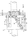
- FIG. 1 includes two spaced brackets 20 and 22 that are bolted to the plate 12.
- a pair of turnbuckles 24 and 26, of a generally conventional design connect the brackets 20 and 22, respectively, to a bracket 30.
- the bracket 30 is generally U-shaped and has two spaced parallel legs 30a and 30b that extend vertically.
- the respective ends of the turnbuckle 24 are mounted for pivotal movement relative to the bracket 20 and the leg 30a of the bracket 30, and the respective ends of the turnbuckle 26 are mounted for pivotal movement relative to the bracket 22 and the leg 30b of the bracket 20, all in a generally conventional manner.
- the turnbuckles 24 and 26 include outer sleeves 24a and 26a, respectively, which, when manually rotated, axially expand or contract the turnbuckles, also in a conventional manner and for reasons to be described.
- An expansion bolt 32 is in threaded engagement with a threaded bore (not shown) provided in the bracket 20 and has a head portion connected to the bracket 30 by a bolt 34 extending through aligned openings in the bracket 30 and through an opening in the head portion.
- An expansion bolt (not shown) similar to bolt 32 is in threaded engagement with a threaded bore (not shown) provided in the bracket 22 and has a head portion connected to the bracket 30 by a bolt (not shown) similar to bolt 34 extending through aligned openings in the bracket 30 and through an opening in the latter head portion.
- the expansion bolt 32 and its corresponding expansion bolt on the opposite side of the assembly 14 can be axially expanded and contracted by rotating the bolts in a conventional manner.
- expansion and contraction of the expansion bolts, including bolt 32, and the turnbuckles 24 and 26, adjust the position of the bracket 30 in an axial direction relative to the shaft 10, as well as its angular position relative to a vertical and horizontal axis.
- Two horizontally-spaced, parallel damping members 40 and 42 are mounted at one of their ends to the bracket 30 by a plurality of bolts, respectively, such as bolt 44.
- the damping members 40 and 42 are rectangular in cross section and extend upright and horizontally.
- a bracket 50 is provided in a spaced relation to the bracket 30 and is connected to the other ends of the damping members 40 and 42 by a plurality of bolts, respectively, such as bolts 52.
- the bracket 50 has a central opening 50a for receiving the shaft 10 with ample clearance.
- Two vertically-spaced, parallel damping members 60 and 62 are mounted at one end to the bracket 50 by a plurality of bolts 64 and 66, respectively.
- the damping members 60 and 62 are rectangular in cross section and extend horizontally relative to the shaft 10.
- the damping members 40, 42, 60 and 62 are angular spaced at ninety degree intervals.
- a generally conventional mechanical bearing such as a roller bearing 170 is connected to the other end of the damping members 60 and 62 by a pair of spaced mounting plates 172a and 172b, respectively, affixed to portion of the roller bearing 170 and provides a mechanical interconnection between the damping members 60 and 62 and the shaft 10.
- a roller bearing 170 has a central opening 170a that receives the shaft 10 as generally known in the art.
- the damping member 60 is formed by three stacked elastomeric damping pads 80a-80c.
- the pad 80a is sandwiched between two relatively thin, plates 82a and 82b, the pad 80b is sandwiched between the plate 82b and an additional plate 82c, and the pad 80c is sandwiched between the plate 82c and an additional plate 82d.
- the damping member 60 will not be completely described herein as it is fully described in the above-identified U.S. patents.
- the damper member 60 has openings therethrough so as to receive the bolts 64 and 74 and thus permit a rigid mounting of the damping member 60 to the bracket 50 and to the plates 172a and 172b. It is understood that the damping members 40, 42 and 62 are substantially identical to the damping member 60 and thus will not be described in detail. The use of two damping members 40 and 42, as well as two damping members 60 and 62, allows radial movement of the roller bearing 170 without causing any tilting, or angular movement, of the bearing 170.
- the mounting plates 172a and 172b and the roller bearing 170 illustrated present merely one example of a mechanical bearing assembly that can be used and the illustration and description of the roller bearing shown in Fig. 2 should not be limiting in any manner in the varieties of mechanical bearings and roller bearing assemblies that can be used to mechanically interconnect the damping plates 60 and 62 and the shaft 10.
- the roller bearing 170 includes an outer race 171a that is securely and rigidly coupled to bracket plate 172a, an inner race 171b securely coupled to and rotatable with shaft 10, and ball bearings 171 c positioned therebetween.
- the general construction of the roller bearing 170 and its interconnection with mounting plates 172a and 172b and shaft 10 are as generally know in the art.
- the support assembly 14 provides a mechanically-coupled support of the shaft 10 in an elevated position relative to the support plate 12 ( FIG. 1 ), transferring radial forces to be carried from the rotating shaft 10 to the support assembly 14 which acts as a damper and a restoring spring to radial displacement of the shaft 10, without any impedance to rotation of the shaft 10.
- the shaft 10 is positioned in the elevated position relative to the support plate 12 as shown in FIG. 1 , and the support assembly 14 is positioned within roller bearing 170.
- the turnbuckles 24 and 26, together with the screws 32 and is opposite-side corresponding screw, are adjusted so that the shaft 10, roller bearing 170 and support assembly 14 can all be properly aligned to decrease forces on the shaft 10 while maximizing the damping abilities of the support assembly 14.
- the support assembly 14 thus provides a low friction, bearing for rotation of the shaft 10. Also, any radial deflection of the shaft 10 causes corresponding movement the support assembly 14. For example, any deflections of the shaft 10 that causes vertical movement of the shaft 10 will cause resultant shear forces to be applied to the damper members 60 and 62 and cause them to move which dampens the deflective movement of the shaft 10.
- any deflections of the shaft 10 that causes movement of roller bearing 170 in a horizontal direction e.g., in a direction substantially parallel to the surface of plate 12, will cause corresponding shear forces to be applied to the damper members 40 and 42 and cause them to deflect in the same manner as discussed above in connection with the damper members 60 and 62.
- deflections of the shaft 10 in a direction having both a horizontal and a vertical component will cause corresponding movement of all of the damper members 40, 42, 60 and 62 in the manners discussed above.
- roller bearing 170 achieves most of the prior benefits of magnetic-type elements as disclosed in the above-identified U.S. patents while using more reliable technology. Additionally, the use of a mechanical bearing such as roller bearing 170 eliminates many of the alignment issues that may possibly come up with respect to use of the magnetic elements. Also, bearings such as roller bearing 170 are smaller, lighter, and less expensive than magnetic elements. Thus, there are no strong axial forces imposed on the shaft that have to be reacted into supporting structure 14 and its damping members. Additionally, bearings such as roller bearing 170 provide less of a blockage for wiring and hydraulics. Also, motion is transferred more efficiently because the mechanical bearing is much stiffer than magnetic disks since there is nothing lost in the spring action between magnets.
- mechanical bearings such as roller bearing 170 may be used when the shaft is part of a curved drive path and may be used with long, flexible, and curved drive shafts while simultaneously providing a source of damping to preclude, for example, excessive motion during start up and dynamic whirl instability while operating at high speeds.
- the mechanical bearing, such as roller bearing 170 therefore provides a low risk approach to quickly achieve many benefits of supercritical shafting regardless of the presence of grease-lubricated mechanical bearings.
- the weight and cost benefits achieved with mechanical bearing in place of magnetic elements may be very significant, and a smaller diameter shaft may be used.
- mechanical bearings, such as roller bearing 170 may provide improved survivability in military applications.
- the additional support assemblies 14 on the shaft 10 will function in a manner substantially identical to that of the support assembly 14 discussed herein and that, when the shaft 10 is of a considerable length, additional support assemblies 14 can be utilized as needed. Also, in situations in which a portion or portions of the shaft 10 must be curved by design due to its particular application, the support assembly 14, and any additional identical support assemblies, can easily be positioned relative to the shaft to deflect the shaft into the desired curvature, thereby avoiding the need for angular misalignment couplings.
- each roller bearing 170 can be formed by a plurality of roller bearings. Further, the number of damping pads, and therefore the associated plates, in each of the damping members can be varied.
- Fig. 3 illustrates another embodiment of the invention.
- Support assembly 214 in Fig. 3 is substantially identical to support 14 described above with respect to Figs. 1 and 2 , except support assembly has four damper members 260 instead of damper members 60, 62, 40 and 42.
- damper members 60, 62, 40, and 42 are a laminate of metal sheets and elastomeric material (as fully disclosed in, for example, U.S. Patent No. 6268676 )
- damper members 260 perform substantially the same function as dampers 60, 62, 40 and 42 but are made as a one-piece, unitary plate member 282 with an elastomeric material 280 positioned within said plate member 282 as seen best in Fig. 4 .
- plate member has a front 284, a rear 286, a top 288, an opposite bottom (not shown in Fig. 4 ) and two sides 290. Each side has at least one slot 292 that extends completely through the plate member 282 between the two corresponding apertures on opposite sides of the plate member 282. As illustrated in Fig. 4 , the plate member 282 can have multiple slots 292 separated by thin portions 294 of the plate member 282. Elastomeric material 280 is inserted into each slot 292 to provide the desired damping characteristics required from the plate member 282. Plate member 282 has bolt holes 296 extending completely therethrough for attachment of the damping member 260 to the other members of the support assembly 214. Plate member 282 is preferably made from metal such as steel. For example, plate member 282 may be formed by electro-discharge machining from a single piece of corrosion resistant steel.
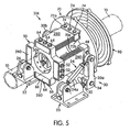
- FIG. 5 illustrates an example substantially identical to the system illustrated, for example, in the above-referenced U.S. Pat. No. 6,427,308 , except that instead of using the laminate damping members as previously known, the support assembly 314 uses damping members 260, which are described above with respect to FIGS. 3 and 4 .
- the support assembly 314 is similar to support assembly 214, except that support assembly 314 employs a magnetic bearing assembly 70, 90 instead of the roller bearing 170 disclosed above.
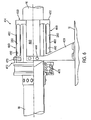
- FIGS. 6-7 illustrate an example of a support assembly 414 that is similar to support assembly 14 illustrated in FIG. 1 except a bracket assembly 450 is employed instead of the assembly of the damping members 40, 42, 60, 62 and the floating bracket 50. That is, bracket assembly 450 replaces the multi-part assembly of damping members 40, 42, 60, 62, bolts, and floating bracket 50. Bracket assembly 450 performs substantially the same functions as the various parts from support assembly 14 that it replaces, except that it, for example, simplifies assembling and replacement associated with those parts it replaces since bracket 450 may be handled as a single part. The bracket assembly 450 is also lighter and more cost-effective than the multi-element part it may replace.
- the support assembly 414 includes a rigid bracket 420 that is rigidly coupled to plate 12.
- Bracket assembly 450 is attached to bracket 420 by bolts 444 extending through bolt holes 445.
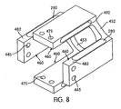
- Bracket assembly 450 includes four damping members 460 and a floating brace 452.
- Each of the damping members 460 includes a plate member 482 having a slot 492 that extends completely through its respective plate member 482 in a manner similar to the slots 292 described above with respect to the embodiment of FIG. 4 .
- Each slot 492 is filled with elastomeric material 280 similar to the material used to fill slots 292 above.
- the elastomeric material 280 can take various forms and can be varied to provide the desired damping characteristics.
- the elastomeric material is a high damping elastomer with a high loss coefficient.
- damping members 460 are illustrated, the number of damping members 40 can be adjusted for the appropriate needs. Also, although only one slot 492 is illustrated, any appropriate number of slots 492 filled with elastomeric material 280 can be used in each damping member 460. For example, there can be three slots 492 in each damping member 460 similar to the three slots 292 illustrated in FIG. 4 .
- the brace 452 interconnects the four spaced plate members 482 and the four plate members 482 and the brace 452 are formed as a one-piece, unitary bracket.
- the unitary bracket that forms brace 452 and plate members 482 is preferably made from metal such as steel.
- the unitary bracket may be formed by electro-discharge machining from a single piece of corrosion resistant steel.
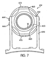
- roller bearing assembly 472 is substantially identical to the roller bearing 170 and the brackets 172a and 172b of support assembly 14, except roller bearing assembly 472 is configured differently to be securably coupled to the two damping members 460. As seen in FIGS. 6 and 7 , the securing that occurs between the damping members 460 and the roller bearing assembly 472 is accomplished with bolts 473 extending through bolt holes 475 in damping members 460.
- roller bearing assembly 472 includes roller bearing 470, which is substantially identical to roller bearing 170 described above and which securably attaches to shaft 10 in a conventional manner.
- brace 452 includes an opening 453 for receiving shaft 10 extending therethrough.
- FIGS. 6-7 includes a support assembly 414 that achieves all of the supporting and damping benefits afforded by support assembly 14 described above, yet includes a one-piece unitary bracket with elastomeric inserts that can be handled as an single element in place of the multiple elements relied upon in support assembly 14 to provide the necessary damping characteristics described. Additionally, the one-piece, unitary bracket is lighter and less expensive to manufacture than the multiple elements it replaces.
- FIG. 9 illustrates yet another example of a support assembly 514 substantially identical to support assembly 414 illustrated in FIGS. 6 and 7 and employs the bracket assembly 450, except the support assembly 514 does not use a mechanical bearing.
- Support assembly 514 instead employs a magnetic bearing assembly 70, 90 similar to that described above with respect to support assembly 314.
Landscapes
- Engineering & Computer Science (AREA)
- General Engineering & Computer Science (AREA)
- Mechanical Engineering (AREA)
- Physics & Mathematics (AREA)
- Acoustics & Sound (AREA)
- Aviation & Aerospace Engineering (AREA)
- Chemical & Material Sciences (AREA)
- Combustion & Propulsion (AREA)
- Vibration Prevention Devices (AREA)
- Support Of The Bearing (AREA)
- Shafts, Cranks, Connecting Bars, And Related Bearings (AREA)
- Pulleys (AREA)
- Fluid-Damping Devices (AREA)
Claims (10)
- Tragsystem (14) für eine sich drehende Welle (10), umfassend:- einen feststehenden Träger;- eine Trägeranordnung (30) mit einem ersten Dämpfungselement (40, 42), das ein erstes feststehendes Ende und ein zweites bewegliches Ende aufweist, wobei das erste feststehende Ende sicher an dem feststehenden Träger befestigt und das zweite bewegliche Ende in einer ersten, mit der Welle bündigen Ebene beweglich ist, wobei die Trägeranordnung eine Halterung (50) aufweist, die sicher an dem zweiten beweglichen Ende des ersten Dämpfungselements (40, 42) befestigt ist, wobei das erste feststehende Ende und das zweite bewegliche Ende des ersten Dämpfungselements (40, 42) unabhängig voneinander an dem feststehenden Träger bzw. der Halterung (50) befestigt sind, wobei die Trägeranordnung weiterhin ein zweites Dämpfungselement (60, 62) mit einem ersten und einem zweiten Ende aufweist, wobei das erste Ende sicher an der Halterung befestigt und das zweite Ende in einer zweiten mit der Welle (10) bündigen Ebene beweglich ist und im Allgemeinen senkrecht zu der ersten Ebene verläuft ist; und- ein Wälzlager (170), das sicher an dem zweiten Ende des zweiten Dämpfungselements befestigt ist, wobei das Wälzlager (170) so ausgestaltet und angeordnet ist, um einen mechanischen Verbund zwischen dem zweiten Ende des Dämpfungselements (60, 62) und der Welle (10) vorzusehen.
- Tragsystem (14) nach Anspruch 1, bei dem das erste Dämpfungselement (40, 42) ein erstes Plattenelement und ein erstes Dämpfungselement, das in dem ersten Plattenelement positioniert ist, einschließt und das zweite Dämpfungselement ein zweites Plattenelement und ein zweites Dämpfungselement, das in dem zweiten Plattenelement positioniert ist, einschließt.
- Tragsystem (14) nach Anspruch 2, bei dem das erste Plattenelement, das zweite Plattenelement und die Halterung gemeinsam ein einstückiges, eigenständiges Trägerelement ausbilden.
- Tragsystem (14) nach Anspruch 3, bei dem sowohl das erste wie auch das zweite Dämpfungselement jeweils aus Elastomermaterial und das Trägerelement aus Metall besteht.
- Tragsystem (14) nach Anspruch 2, bei dem das erste Plattenelement (282) aus einem einstückigen, eigenständigen Element und das zweite Plattenelement (282) aus einem einstückigen, eigenständigen Element besteht.
- Tragsystem (14) nach Anspruch 5, bei dem sowohl das erste wie auch das zweite Dämpfungselement jeweils aus Elastomermaterial (280) und das erste wie auch das zweite Plattenelement aus Metall besteht.
- Tragsystem (14) nach einem der Ansprüche 1 bis 6, bei dem das erste wie auch das zweite Dämpfungselement jeweils eine Einzelplatte einschließt, die eine mittige Durchgangsöffnung und ein in der mittigen Öffnung positioniertes Dämpfungselement aufweist.
- Tragsystem (14) nach Anspruch 7, bei dem das Dämpfungselement ein Material einschließt, das im Wesentlichen einen ganzen, in der mittigen Öffnung definierten Raum einnimmt.
- Tragsystem (14) nach Anspruch 7, bei dem die erste Platte, die zweite Platte und die Halterung gemeinsam ein einstückiges, eigenständiges Trägerelement ausbilden.
- Tragsystem (14) nach einem der Ansprüche 1 bis 6, bei dem das erste wie auch das zweite Dämpfungselement jeweils eine Einzelplatte einschließt, die eine einzelne, mittige Durchgangsöffnung sowie ein in der einzelnen mittigen Öffnung positioniertes Dämpfungselement aufweist, wobei das Dämpfungselement ein Material einschließt, das im Wesentlichen einen ganzen, in der einzigen mittigen Öffnung definierten Raum einnimmt und wobei die Einzelplatte des ersten Dämpfungselements, die Einzelplatte des zweiten Dämpfungselements und die Halterung gemeinsam ein einstückiges, eigenständiges Trägerelement ausbilden.
Priority Applications (2)
| Application Number | Priority Date | Filing Date | Title |
|---|---|---|---|
| EP11167356.2A EP2363943B1 (de) | 2004-03-12 | 2005-01-27 | Dämpfer |
| EP11167337.2A EP2367268B1 (de) | 2004-03-12 | 2005-01-27 | Dämpferlageranordnung für eine überkritische Antriebswelle |
Applications Claiming Priority (2)
| Application Number | Priority Date | Filing Date | Title |
|---|---|---|---|
| US10/798,279 US7109619B2 (en) | 2004-03-12 | 2004-03-12 | Damper support assembly for a supercritical drive shaft |
| PCT/US2005/003009 WO2005091775A2 (en) | 2004-03-12 | 2005-01-27 | Damper support assembly for a supercritical drive shaft |
Related Child Applications (3)
| Application Number | Title | Priority Date | Filing Date |
|---|---|---|---|
| EP11167356.2A Division EP2363943B1 (de) | 2004-03-12 | 2005-01-27 | Dämpfer |
| EP11167356.2 Division-Into | 2011-05-24 | ||
| EP11167337.2 Division-Into | 2011-05-24 |
Publications (3)
| Publication Number | Publication Date |
|---|---|
| EP1730833A2 EP1730833A2 (de) | 2006-12-13 |
| EP1730833A4 EP1730833A4 (de) | 2009-04-01 |
| EP1730833B1 true EP1730833B1 (de) | 2012-02-29 |
Family
ID=34920250
Family Applications (3)
| Application Number | Title | Priority Date | Filing Date |
|---|---|---|---|
| EP11167356.2A Expired - Lifetime EP2363943B1 (de) | 2004-03-12 | 2005-01-27 | Dämpfer |
| EP05712445A Expired - Lifetime EP1730833B1 (de) | 2004-03-12 | 2005-01-27 | Dämpferlageranordnung für eine überkritische antriebswelle |
| EP11167337.2A Expired - Lifetime EP2367268B1 (de) | 2004-03-12 | 2005-01-27 | Dämpferlageranordnung für eine überkritische Antriebswelle |
Family Applications Before (1)
| Application Number | Title | Priority Date | Filing Date |
|---|---|---|---|
| EP11167356.2A Expired - Lifetime EP2363943B1 (de) | 2004-03-12 | 2005-01-27 | Dämpfer |
Family Applications After (1)
| Application Number | Title | Priority Date | Filing Date |
|---|---|---|---|
| EP11167337.2A Expired - Lifetime EP2367268B1 (de) | 2004-03-12 | 2005-01-27 | Dämpferlageranordnung für eine überkritische Antriebswelle |
Country Status (6)
| Country | Link |
|---|---|
| US (1) | US7109619B2 (de) |
| EP (3) | EP2363943B1 (de) |
| JP (1) | JP2007528967A (de) |
| AT (1) | ATE547834T1 (de) |
| CA (2) | CA2766191C (de) |
| WO (1) | WO2005091775A2 (de) |
Families Citing this family (9)
| Publication number | Priority date | Publication date | Assignee | Title |
|---|---|---|---|---|
| FR2908736B1 (fr) * | 2006-11-16 | 2009-07-17 | Eurocopter France | Systeme de transmission mecanique a amortisseur magnetique pour giravion |
| DE102009031887B4 (de) * | 2009-07-06 | 2012-06-06 | Siemens Aktiengesellschaft | Fanglager zum Auffangen einer Rotorwelle einer Maschine |
| US8747054B2 (en) | 2011-01-24 | 2014-06-10 | United Technologies Corporation | Bearing system for gas turbine engine |
| FR2992702B1 (fr) | 2012-06-28 | 2014-07-04 | Eurocopter France | Dispositif d'accouplement par aboutement d'un arbre de transmission supercritique, pour l'entrainement d'un rotor de giravion notamment |
| US10287005B2 (en) * | 2015-03-13 | 2019-05-14 | Bell Helicopter Textron Inc. | Friction damper with centering flexure |
| US11480528B2 (en) * | 2018-09-28 | 2022-10-25 | Hamilton Sundstrand Corporation | And inspection method of aircraft drive shafts |
| CN111431316B (zh) * | 2020-04-13 | 2020-11-27 | 深圳市科创兴电机科技有限公司 | 一种无刷电机 |
| CN112283288B (zh) * | 2020-11-26 | 2022-07-19 | 电子科技大学中山学院 | 一种新能源汽车电驱装置 |
| CN113074216A (zh) * | 2021-04-27 | 2021-07-06 | 上海交通大学 | 一种超临界轴系振动抑制装置 |
Family Cites Families (64)
| Publication number | Priority date | Publication date | Assignee | Title |
|---|---|---|---|---|
| US450867A (en) * | 1891-04-21 | landis | ||
| US1845551A (en) * | 1931-04-29 | 1932-02-16 | Mitzi Josef | Motor supporting arrangement |
| US2063216A (en) * | 1932-11-30 | 1936-12-08 | Fed Spring Company | Resilient connection |
| US2725266A (en) | 1953-04-20 | 1955-11-29 | Gen Electric | Magnetic suspension |
| US3041485A (en) * | 1958-05-29 | 1962-06-26 | Paul L Jolley | Removable power pack for remotely controlled toys |
| DE1020930B (de) * | 1958-11-13 | 1957-12-12 | Siebtechnik G.m.b.H., Mülheim/Ruhr-Speldorf | Schwingzentrifuge |
| DE1162137B (de) * | 1960-05-25 | 1964-01-30 | Barry Controls Inc | Vorgefertigtes lastaufnehmendes Bauelement fuer Bauwerke, Maschinen, Geraete od. dgl. |
| US3293462A (en) * | 1964-07-31 | 1966-12-20 | Spalding A G & Bros Inc | Power unit for toys or the like |
| US3628284A (en) * | 1970-02-02 | 1971-12-21 | Mattel Inc | Miniature high-speed electric toy racing vehicle with rechargeable battery |
| US3622822A (en) * | 1970-03-04 | 1971-11-23 | Philips Corp | Enclosure for electric motor |
| US3634969A (en) * | 1971-03-19 | 1972-01-18 | Mattel Inc | Dune buggy toy |
| US3811740A (en) | 1971-04-24 | 1974-05-21 | Cnen | Self-centering rotary magnetic suspension device |
| US3733744A (en) * | 1972-02-09 | 1973-05-22 | Mattel Inc | Power module for driving vehicle-propelling element,including stationary axle means mounting said element |
| US3827181A (en) * | 1972-03-23 | 1974-08-06 | Mabuchi Motor Co | Electrically driven model airplane |
| US3830595A (en) * | 1972-08-16 | 1974-08-20 | Tappan Co | Motor mounting support |
| US3977758A (en) * | 1973-06-01 | 1976-08-31 | Mabuchi Motor Co. Ltd. | Cell holding device |
| GB1473699A (en) * | 1973-07-31 | 1977-05-18 | Mabuchi Motor Co | Motor and switch assembly |
| US3959921A (en) * | 1974-12-04 | 1976-06-01 | Nylint Corporation | Toy vehicle with operator-simulating doll |
| US4028571A (en) * | 1976-02-25 | 1977-06-07 | Crown Controls Corporation | Control mechanism for remotely mounted motor |
| US4073086A (en) * | 1976-06-09 | 1978-02-14 | Takara Co., Ltd. | Vehicle toy |
| DE2632586C2 (de) * | 1976-07-20 | 1983-05-19 | Gesellschaft für Kernverfahrenstechnik mbH, 5170 Jülich | Verfahren und Vorrichtung zum Durchlaufen kritischer Drehzahlen langgestreckter Rotoren |
| US4145626A (en) | 1977-02-14 | 1979-03-20 | Aroshidze Jury V | Elastic mounting of a core in an electric machine stator |
| US4183173A (en) * | 1978-03-28 | 1980-01-15 | Takara Co., Ltd. | Toy assembly with interchangeable parts and detachable appendages |
| US4202551A (en) | 1978-05-11 | 1980-05-13 | Darnall Tom A Jr | Acoustic dampening assembly for record player turntable |
| LU80296A1 (fr) | 1978-09-28 | 1980-04-21 | Bekaert Sa Nv | Structures amortissant des vibrations mecaniques |
| US4214796A (en) * | 1978-10-19 | 1980-07-29 | General Electric Company | Bearing assembly with multiple squeeze film damper apparatus |
| US4511343A (en) * | 1980-02-14 | 1985-04-16 | Delmar K. Everitt | Wheeled miniature toy vehicle with easily selectable plural modes of use |
| US4425813A (en) * | 1981-06-04 | 1984-01-17 | Wadensten Theodore S | Vibration dampening apparatus for motor actuated eccentric forces |
| US4457667A (en) * | 1980-12-11 | 1984-07-03 | United Technologies Corporation | Viscous damper with rotor centering means |
| US4406642A (en) | 1981-04-13 | 1983-09-27 | Dresser Industries, Inc. | Shaft dampening apparatus |
| JPS622924Y2 (de) | 1981-06-10 | 1987-01-23 | ||
| JPS5822841U (ja) | 1981-08-06 | 1983-02-12 | アルプス電気株式会社 | モ−タ−の保持装置 |
| US4406085A (en) * | 1981-12-21 | 1983-09-27 | Mattel, Inc. | Modular radio control for use with multiple toy vehicles |
| US4430011A (en) * | 1982-08-02 | 1984-02-07 | Union Carbide Corporation | Integral bearing system |
| JPS60125427A (ja) * | 1983-12-08 | 1985-07-04 | Nhk Spring Co Ltd | Frp板ばね |
| US4726112A (en) | 1984-12-14 | 1988-02-23 | General Electric Company | Method of assembling a dynamoelectric machine |
| US4978581A (en) | 1986-02-07 | 1990-12-18 | Bridgestone Construction | Anti-seismic bearing |
| US4764150A (en) * | 1987-04-30 | 1988-08-16 | Kabushiki Kaisha Uchino Shoten | Running toy |
| US4889516A (en) * | 1987-11-16 | 1989-12-26 | Buddy L Corp. | Plug-in module for motorized toy vehicle |
| JPH043793U (de) * | 1990-04-23 | 1992-01-14 | ||
| FR2667916B1 (fr) * | 1990-10-16 | 1992-12-04 | Caoutchouc Manuf Plastique | Dispositif de tension d'un galet tendeur pour transmission par lien souple, fonctionnant par deformation elastique d'un solide parallelepipedique deformable. |
| US5177387A (en) | 1990-12-04 | 1993-01-05 | University Of Houston-University Park | High temperature superconducting magnetic bearings |
| JP3051222B2 (ja) * | 1991-10-25 | 2000-06-12 | マブチモーター株式会社 | 小型モータ |
| US5621260A (en) * | 1992-10-07 | 1997-04-15 | Matsushita Electric Industrial Co., Ltd. | Coreless motor |
| US5376850A (en) | 1993-07-02 | 1994-12-27 | Seagate Technology, Inc. | Audible noise reduction in a disc drive |
| DE4334202A1 (de) | 1993-10-07 | 1995-04-13 | Bosch Gmbh Robert | Elektromotor mit einem zumindest annähernd rohrförmigen Gehäuseabschnitt |
| US5495221A (en) | 1994-03-09 | 1996-02-27 | The Regents Of The University Of California | Dynamically stable magnetic suspension/bearing system |
| US5521448A (en) | 1994-08-01 | 1996-05-28 | Mechanical Technology Incorporated | Damping for passive magnetic bearings |
| US5889349A (en) * | 1995-10-23 | 1999-03-30 | Namiki Precision Jewel Co., Ltd. | Cylindrical coreless vibrating motor |
| US5506459A (en) | 1995-09-15 | 1996-04-09 | Ritts; Gary | Magnetically balanced spinning apparatus |
| US5847480A (en) | 1995-11-03 | 1998-12-08 | The Regents Of The University Of California | Passive magnetic bearing element with minimal power losses |
| JP3400632B2 (ja) * | 1995-12-08 | 2003-04-28 | セイコーインスツルメンツ株式会社 | スピンドルモータ |
| US5762533A (en) * | 1996-01-04 | 1998-06-09 | Mattel, Inc. | Toy vehicle with adjustably positioned wheels |
| US5900685A (en) * | 1996-02-06 | 1999-05-04 | Light & Sound Design, Ltd. | Anti-noise system for a moving object |
| JPH09271155A (ja) * | 1996-03-29 | 1997-10-14 | Matsushita Electric Ind Co Ltd | 円筒型振動発生モータの取付方法 |
| US5835006A (en) * | 1996-05-22 | 1998-11-10 | Moorola, Inc. | Vibrator assembly |
| US6021992A (en) | 1997-06-23 | 2000-02-08 | Taichung Machinery Works Co., Ltd. | Passive vibration isolating system |
| US6074271A (en) * | 1997-08-26 | 2000-06-13 | Derrah; Steven | Radio controlled skateboard with robot |
| DE19811098C2 (de) * | 1998-03-13 | 2003-07-03 | Wifag Maschf | Lagerung eines Rotationskörpers einer Druckmaschine |
| US6057618A (en) | 1998-04-01 | 2000-05-02 | Bell Helicopter Textron, Inc. | Support assembly for a rotating shaft |
| JP2002166064A (ja) * | 2000-12-05 | 2002-06-11 | Tomy Co Ltd | 走行玩具用サスペンション及び走行玩具 |
| JP3925048B2 (ja) * | 2000-07-06 | 2007-06-06 | スズキ株式会社 | 電動車両 |
| US6508322B2 (en) * | 2000-11-09 | 2003-01-21 | Mattel, Inc. | Battery retaining system for children's ride-on vehicles |
| US7094125B2 (en) * | 2000-11-28 | 2006-08-22 | Tomy Company, Ltd. | Steering device for toy and running toy |
-
2004
- 2004-03-12 US US10/798,279 patent/US7109619B2/en not_active Expired - Lifetime
-
2005
- 2005-01-27 CA CA2766191A patent/CA2766191C/en not_active Expired - Lifetime
- 2005-01-27 EP EP11167356.2A patent/EP2363943B1/de not_active Expired - Lifetime
- 2005-01-27 AT AT05712445T patent/ATE547834T1/de active
- 2005-01-27 EP EP05712445A patent/EP1730833B1/de not_active Expired - Lifetime
- 2005-01-27 WO PCT/US2005/003009 patent/WO2005091775A2/en not_active Ceased
- 2005-01-27 EP EP11167337.2A patent/EP2367268B1/de not_active Expired - Lifetime
- 2005-01-27 CA CA2559528A patent/CA2559528C/en not_active Expired - Lifetime
- 2005-01-27 JP JP2007502808A patent/JP2007528967A/ja active Pending
Also Published As
| Publication number | Publication date |
|---|---|
| CA2559528A1 (en) | 2005-10-06 |
| CA2766191A1 (en) | 2005-10-06 |
| WO2005091775A3 (en) | 2006-05-18 |
| EP1730833A4 (de) | 2009-04-01 |
| CA2766191C (en) | 2016-04-05 |
| ATE547834T1 (de) | 2012-03-15 |
| EP1730833A2 (de) | 2006-12-13 |
| WO2005091775A2 (en) | 2005-10-06 |
| WO2005091775B1 (en) | 2006-06-29 |
| CA2559528C (en) | 2013-07-02 |
| JP2007528967A (ja) | 2007-10-18 |
| EP2367268B1 (de) | 2013-05-08 |
| EP2363943A1 (de) | 2011-09-07 |
| US7109619B2 (en) | 2006-09-19 |
| EP2363943B1 (de) | 2014-04-30 |
| EP2367268A1 (de) | 2011-09-21 |
| US20050200219A1 (en) | 2005-09-15 |
Similar Documents
| Publication | Publication Date | Title |
|---|---|---|
| US6057618A (en) | Support assembly for a rotating shaft | |
| EP1730833B1 (de) | Dämpferlageranordnung für eine überkritische antriebswelle | |
| US8157062B2 (en) | Wheel and brake assembly | |
| US5201585A (en) | Fluid film journal bearing with squeeze film damper for turbomachinery | |
| EP2126365B1 (de) | Vakuumpumpe | |
| WO2000017049A1 (en) | Multi-linkage suspension system including outboard isolators | |
| JPS6148611A (ja) | 回転軸又は回転軸用軸受のためのダンパ型支持構造体 | |
| EP0918950B1 (de) | Drehelastische kupplung mit gewölbten elementen um grosse drehsteifheit zu halten trotz axialer fehlausrichtung | |
| US6379046B1 (en) | Modular support structure for hydrodynamic bearing | |
| US6170989B1 (en) | Modular support structure for hydrodynamic bearing | |
| RU1806302C (ru) | Осевой опорный узел с компенсацией перекоса | |
| CN107735594B (zh) | 轴向减振器 | |
| EP0596039B1 (de) | Ausgleichung des kinematischen effektes in einer blattverstellungssteuerung eines drehflügelflugzeuges | |
| JP2015161411A (ja) | 第1の軸受層と第2の軸受層とを備えた軸受装置 | |
| KR20070031884A (ko) | 초임계 구동축의 댐퍼 지지 조립체 | |
| WO2002028710A1 (en) | Elastomeric bearing | |
| EP1262676B1 (de) | Kraftverstärkungsmechanismus | |
| EP2236415B1 (de) | Rotorvorrichtung und verfahren für ein flugzeug mit vertikalem auftrieb | |
| EP1203439B1 (de) | Vorrichtung zum erzeugen einer hin und hergehenden bewegung und lineares aufhängungselement dafür | |
| US5988890A (en) | Rotor shaft | |
| JP2022110863A (ja) | 連結部材 |
Legal Events
| Date | Code | Title | Description |
|---|---|---|---|
| PUAI | Public reference made under article 153(3) epc to a published international application that has entered the european phase |
Free format text: ORIGINAL CODE: 0009012 |
|
| 17P | Request for examination filed |
Effective date: 20060920 |
|
| AK | Designated contracting states |
Kind code of ref document: A2 Designated state(s): AT BE BG CH CY CZ DE DK EE ES FI FR GB GR HU IE IS IT LI LT LU MC NL PL PT RO SE SI SK TR |
|
| AX | Request for extension of the european patent |
Extension state: AL BA HR LV MK YU |
|
| R17D | Deferred search report published (corrected) |
Effective date: 20060629 |
|
| DAX | Request for extension of the european patent (deleted) | ||
| A4 | Supplementary search report drawn up and despatched |
Effective date: 20090303 |
|
| 17Q | First examination report despatched |
Effective date: 20090608 |
|
| GRAP | Despatch of communication of intention to grant a patent |
Free format text: ORIGINAL CODE: EPIDOSNIGR1 |
|
| GRAS | Grant fee paid |
Free format text: ORIGINAL CODE: EPIDOSNIGR3 |
|
| GRAA | (expected) grant |
Free format text: ORIGINAL CODE: 0009210 |
|
| AK | Designated contracting states |
Kind code of ref document: B1 Designated state(s): AT BE BG CH CY CZ DE DK EE ES FI FR GB GR HU IE IS IT LI LT LU MC NL PL PT RO SE SI SK TR |
|
| REG | Reference to a national code |
Ref country code: GB Ref legal event code: FG4D Ref country code: CH Ref legal event code: EP |
|
| REG | Reference to a national code |
Ref country code: AT Ref legal event code: REF Ref document number: 547834 Country of ref document: AT Kind code of ref document: T Effective date: 20120315 |
|
| REG | Reference to a national code |
Ref country code: IE Ref legal event code: FG4D |
|
| REG | Reference to a national code |
Ref country code: DE Ref legal event code: R096 Ref document number: 602005032886 Country of ref document: DE Effective date: 20120426 |
|
| REG | Reference to a national code |
Ref country code: NL Ref legal event code: VDEP Effective date: 20120229 |
|
| LTIE | Lt: invalidation of european patent or patent extension |
Effective date: 20120229 |
|
| PG25 | Lapsed in a contracting state [announced via postgrant information from national office to epo] |
Ref country code: NL Free format text: LAPSE BECAUSE OF FAILURE TO SUBMIT A TRANSLATION OF THE DESCRIPTION OR TO PAY THE FEE WITHIN THE PRESCRIBED TIME-LIMIT Effective date: 20120229 Ref country code: LT Free format text: LAPSE BECAUSE OF FAILURE TO SUBMIT A TRANSLATION OF THE DESCRIPTION OR TO PAY THE FEE WITHIN THE PRESCRIBED TIME-LIMIT Effective date: 20120229 Ref country code: IS Free format text: LAPSE BECAUSE OF FAILURE TO SUBMIT A TRANSLATION OF THE DESCRIPTION OR TO PAY THE FEE WITHIN THE PRESCRIBED TIME-LIMIT Effective date: 20120629 |
|
| PG25 | Lapsed in a contracting state [announced via postgrant information from national office to epo] |
Ref country code: BE Free format text: LAPSE BECAUSE OF FAILURE TO SUBMIT A TRANSLATION OF THE DESCRIPTION OR TO PAY THE FEE WITHIN THE PRESCRIBED TIME-LIMIT Effective date: 20120229 Ref country code: GR Free format text: LAPSE BECAUSE OF FAILURE TO SUBMIT A TRANSLATION OF THE DESCRIPTION OR TO PAY THE FEE WITHIN THE PRESCRIBED TIME-LIMIT Effective date: 20120530 Ref country code: FI Free format text: LAPSE BECAUSE OF FAILURE TO SUBMIT A TRANSLATION OF THE DESCRIPTION OR TO PAY THE FEE WITHIN THE PRESCRIBED TIME-LIMIT Effective date: 20120229 Ref country code: PT Free format text: LAPSE BECAUSE OF FAILURE TO SUBMIT A TRANSLATION OF THE DESCRIPTION OR TO PAY THE FEE WITHIN THE PRESCRIBED TIME-LIMIT Effective date: 20120629 |
|
| REG | Reference to a national code |
Ref country code: AT Ref legal event code: MK05 Ref document number: 547834 Country of ref document: AT Kind code of ref document: T Effective date: 20120229 |
|
| PG25 | Lapsed in a contracting state [announced via postgrant information from national office to epo] |
Ref country code: CY Free format text: LAPSE BECAUSE OF FAILURE TO SUBMIT A TRANSLATION OF THE DESCRIPTION OR TO PAY THE FEE WITHIN THE PRESCRIBED TIME-LIMIT Effective date: 20120229 |
|
| PG25 | Lapsed in a contracting state [announced via postgrant information from national office to epo] |
Ref country code: PL Free format text: LAPSE BECAUSE OF FAILURE TO SUBMIT A TRANSLATION OF THE DESCRIPTION OR TO PAY THE FEE WITHIN THE PRESCRIBED TIME-LIMIT Effective date: 20120229 Ref country code: DK Free format text: LAPSE BECAUSE OF FAILURE TO SUBMIT A TRANSLATION OF THE DESCRIPTION OR TO PAY THE FEE WITHIN THE PRESCRIBED TIME-LIMIT Effective date: 20120229 Ref country code: RO Free format text: LAPSE BECAUSE OF FAILURE TO SUBMIT A TRANSLATION OF THE DESCRIPTION OR TO PAY THE FEE WITHIN THE PRESCRIBED TIME-LIMIT Effective date: 20120229 Ref country code: CZ Free format text: LAPSE BECAUSE OF FAILURE TO SUBMIT A TRANSLATION OF THE DESCRIPTION OR TO PAY THE FEE WITHIN THE PRESCRIBED TIME-LIMIT Effective date: 20120229 Ref country code: SE Free format text: LAPSE BECAUSE OF FAILURE TO SUBMIT A TRANSLATION OF THE DESCRIPTION OR TO PAY THE FEE WITHIN THE PRESCRIBED TIME-LIMIT Effective date: 20120229 Ref country code: SI Free format text: LAPSE BECAUSE OF FAILURE TO SUBMIT A TRANSLATION OF THE DESCRIPTION OR TO PAY THE FEE WITHIN THE PRESCRIBED TIME-LIMIT Effective date: 20120229 Ref country code: EE Free format text: LAPSE BECAUSE OF FAILURE TO SUBMIT A TRANSLATION OF THE DESCRIPTION OR TO PAY THE FEE WITHIN THE PRESCRIBED TIME-LIMIT Effective date: 20120229 |
|
| PG25 | Lapsed in a contracting state [announced via postgrant information from national office to epo] |
Ref country code: SK Free format text: LAPSE BECAUSE OF FAILURE TO SUBMIT A TRANSLATION OF THE DESCRIPTION OR TO PAY THE FEE WITHIN THE PRESCRIBED TIME-LIMIT Effective date: 20120229 |
|
| PLBE | No opposition filed within time limit |
Free format text: ORIGINAL CODE: 0009261 |
|
| STAA | Information on the status of an ep patent application or granted ep patent |
Free format text: STATUS: NO OPPOSITION FILED WITHIN TIME LIMIT |
|
| PG25 | Lapsed in a contracting state [announced via postgrant information from national office to epo] |
Ref country code: AT Free format text: LAPSE BECAUSE OF FAILURE TO SUBMIT A TRANSLATION OF THE DESCRIPTION OR TO PAY THE FEE WITHIN THE PRESCRIBED TIME-LIMIT Effective date: 20120229 |
|
| 26N | No opposition filed |
Effective date: 20121130 |
|
| REG | Reference to a national code |
Ref country code: DE Ref legal event code: R097 Ref document number: 602005032886 Country of ref document: DE Effective date: 20121130 |
|
| PG25 | Lapsed in a contracting state [announced via postgrant information from national office to epo] |
Ref country code: ES Free format text: LAPSE BECAUSE OF FAILURE TO SUBMIT A TRANSLATION OF THE DESCRIPTION OR TO PAY THE FEE WITHIN THE PRESCRIBED TIME-LIMIT Effective date: 20120609 |
|
| PG25 | Lapsed in a contracting state [announced via postgrant information from national office to epo] |
Ref country code: BG Free format text: LAPSE BECAUSE OF FAILURE TO SUBMIT A TRANSLATION OF THE DESCRIPTION OR TO PAY THE FEE WITHIN THE PRESCRIBED TIME-LIMIT Effective date: 20120529 |
|
| PG25 | Lapsed in a contracting state [announced via postgrant information from national office to epo] |
Ref country code: MC Free format text: LAPSE BECAUSE OF NON-PAYMENT OF DUE FEES Effective date: 20130131 |
|
| REG | Reference to a national code |
Ref country code: CH Ref legal event code: PL |
|
| REG | Reference to a national code |
Ref country code: IE Ref legal event code: MM4A |
|
| PG25 | Lapsed in a contracting state [announced via postgrant information from national office to epo] |
Ref country code: LI Free format text: LAPSE BECAUSE OF NON-PAYMENT OF DUE FEES Effective date: 20130131 Ref country code: CH Free format text: LAPSE BECAUSE OF NON-PAYMENT OF DUE FEES Effective date: 20130131 |
|
| PG25 | Lapsed in a contracting state [announced via postgrant information from national office to epo] |
Ref country code: IE Free format text: LAPSE BECAUSE OF NON-PAYMENT OF DUE FEES Effective date: 20130127 |
|
| PG25 | Lapsed in a contracting state [announced via postgrant information from national office to epo] |
Ref country code: TR Free format text: LAPSE BECAUSE OF FAILURE TO SUBMIT A TRANSLATION OF THE DESCRIPTION OR TO PAY THE FEE WITHIN THE PRESCRIBED TIME-LIMIT Effective date: 20120229 |
|
| PG25 | Lapsed in a contracting state [announced via postgrant information from national office to epo] |
Ref country code: HU Free format text: LAPSE BECAUSE OF FAILURE TO SUBMIT A TRANSLATION OF THE DESCRIPTION OR TO PAY THE FEE WITHIN THE PRESCRIBED TIME-LIMIT; INVALID AB INITIO Effective date: 20050127 Ref country code: LU Free format text: LAPSE BECAUSE OF NON-PAYMENT OF DUE FEES Effective date: 20130127 |
|
| REG | Reference to a national code |
Ref country code: FR Ref legal event code: PLFP Year of fee payment: 12 |
|
| REG | Reference to a national code |
Ref country code: FR Ref legal event code: PLFP Year of fee payment: 13 |
|
| REG | Reference to a national code |
Ref country code: FR Ref legal event code: PLFP Year of fee payment: 14 |
|
| PGFP | Annual fee paid to national office [announced via postgrant information from national office to epo] |
Ref country code: FR Payment date: 20230125 Year of fee payment: 19 |
|
| PGFP | Annual fee paid to national office [announced via postgrant information from national office to epo] |
Ref country code: GB Payment date: 20230127 Year of fee payment: 19 Ref country code: DE Payment date: 20230127 Year of fee payment: 19 |
|
| PGFP | Annual fee paid to national office [announced via postgrant information from national office to epo] |
Ref country code: IT Payment date: 20240122 Year of fee payment: 20 |
|
| REG | Reference to a national code |
Ref country code: DE Ref legal event code: R119 Ref document number: 602005032886 Country of ref document: DE |
|
| GBPC | Gb: european patent ceased through non-payment of renewal fee |
Effective date: 20240127 |
|
| PG25 | Lapsed in a contracting state [announced via postgrant information from national office to epo] |
Ref country code: DE Free format text: LAPSE BECAUSE OF NON-PAYMENT OF DUE FEES Effective date: 20240801 |
|
| PG25 | Lapsed in a contracting state [announced via postgrant information from national office to epo] |
Ref country code: GB Free format text: LAPSE BECAUSE OF NON-PAYMENT OF DUE FEES Effective date: 20240127 |
|
| PG25 | Lapsed in a contracting state [announced via postgrant information from national office to epo] |
Ref country code: FR Free format text: LAPSE BECAUSE OF NON-PAYMENT OF DUE FEES Effective date: 20240131 |
|
| PG25 | Lapsed in a contracting state [announced via postgrant information from national office to epo] |
Ref country code: GB Free format text: LAPSE BECAUSE OF NON-PAYMENT OF DUE FEES Effective date: 20240127 Ref country code: FR Free format text: LAPSE BECAUSE OF NON-PAYMENT OF DUE FEES Effective date: 20240131 Ref country code: DE Free format text: LAPSE BECAUSE OF NON-PAYMENT OF DUE FEES Effective date: 20240801 |