EP1729629B1 - Bilddarstellung von verborgenen strukturen - Google Patents
Bilddarstellung von verborgenen strukturen Download PDFInfo
- Publication number
- EP1729629B1 EP1729629B1 EP05710889A EP05710889A EP1729629B1 EP 1729629 B1 EP1729629 B1 EP 1729629B1 EP 05710889 A EP05710889 A EP 05710889A EP 05710889 A EP05710889 A EP 05710889A EP 1729629 B1 EP1729629 B1 EP 1729629B1
- Authority
- EP
- European Patent Office
- Prior art keywords
- image
- light source
- analysis
- visual
- light
- Prior art date
- Legal status (The legal status is an assumption and is not a legal conclusion. Google has not performed a legal analysis and makes no representation as to the accuracy of the status listed.)
- Expired - Lifetime
Links
Images


Classifications
-
- A—HUMAN NECESSITIES
- A61—MEDICAL OR VETERINARY SCIENCE; HYGIENE
- A61B—DIAGNOSIS; SURGERY; IDENTIFICATION
- A61B5/00—Measuring for diagnostic purposes; Identification of persons
- A61B5/0059—Measuring for diagnostic purposes; Identification of persons using light, e.g. diagnosis by transillumination, diascopy, fluorescence
- A61B5/0062—Arrangements for scanning
- A61B5/0064—Body surface scanning
-
- A—HUMAN NECESSITIES
- A61—MEDICAL OR VETERINARY SCIENCE; HYGIENE
- A61B—DIAGNOSIS; SURGERY; IDENTIFICATION
- A61B5/00—Measuring for diagnostic purposes; Identification of persons
- A61B5/48—Other medical applications
- A61B5/4887—Locating particular structures in or on the body
- A61B5/489—Blood vessels
-
- G—PHYSICS
- G06—COMPUTING OR CALCULATING; COUNTING
- G06T—IMAGE DATA PROCESSING OR GENERATION, IN GENERAL
- G06T7/00—Image analysis
- G06T7/10—Segmentation; Edge detection
- G06T7/12—Edge-based segmentation
-
- G—PHYSICS
- G06—COMPUTING OR CALCULATING; COUNTING
- G06T—IMAGE DATA PROCESSING OR GENERATION, IN GENERAL
- G06T7/00—Image analysis
- G06T7/10—Segmentation; Edge detection
- G06T7/174—Segmentation; Edge detection involving the use of two or more images
-
- A—HUMAN NECESSITIES
- A61—MEDICAL OR VETERINARY SCIENCE; HYGIENE
- A61B—DIAGNOSIS; SURGERY; IDENTIFICATION
- A61B2562/00—Details of sensors; Constructional details of sensor housings or probes; Accessories for sensors
- A61B2562/02—Details of sensors specially adapted for in-vivo measurements
- A61B2562/0233—Special features of optical sensors or probes classified in A61B5/00
- A61B2562/0242—Special features of optical sensors or probes classified in A61B5/00 for varying or adjusting the optical path length in the tissue
-
- G—PHYSICS
- G01—MEASURING; TESTING
- G01N—INVESTIGATING OR ANALYSING MATERIALS BY DETERMINING THEIR CHEMICAL OR PHYSICAL PROPERTIES
- G01N21/00—Investigating or analysing materials by the use of optical means, i.e. using sub-millimetre waves, infrared, visible or ultraviolet light
- G01N21/17—Systems in which incident light is modified in accordance with the properties of the material investigated
- G01N21/25—Colour; Spectral properties, i.e. comparison of effect of material on the light at two or more different wavelengths or wavelength bands
- G01N21/31—Investigating relative effect of material at wavelengths characteristic of specific elements or molecules, e.g. atomic absorption spectrometry
- G01N21/35—Investigating relative effect of material at wavelengths characteristic of specific elements or molecules, e.g. atomic absorption spectrometry using infrared light
- G01N21/359—Investigating relative effect of material at wavelengths characteristic of specific elements or molecules, e.g. atomic absorption spectrometry using infrared light using near infrared light
-
- G—PHYSICS
- G06—COMPUTING OR CALCULATING; COUNTING
- G06T—IMAGE DATA PROCESSING OR GENERATION, IN GENERAL
- G06T2207/00—Indexing scheme for image analysis or image enhancement
- G06T2207/10—Image acquisition modality
- G06T2207/10048—Infrared image
-
- G—PHYSICS
- G06—COMPUTING OR CALCULATING; COUNTING
- G06T—IMAGE DATA PROCESSING OR GENERATION, IN GENERAL
- G06T2207/00—Indexing scheme for image analysis or image enhancement
- G06T2207/20—Special algorithmic details
- G06T2207/20212—Image combination
- G06T2207/20224—Image subtraction
-
- G—PHYSICS
- G06—COMPUTING OR CALCULATING; COUNTING
- G06T—IMAGE DATA PROCESSING OR GENERATION, IN GENERAL
- G06T2207/00—Indexing scheme for image analysis or image enhancement
- G06T2207/30—Subject of image; Context of image processing
- G06T2207/30004—Biomedical image processing
- G06T2207/30076—Plethysmography
-
- G—PHYSICS
- G06—COMPUTING OR CALCULATING; COUNTING
- G06T—IMAGE DATA PROCESSING OR GENERATION, IN GENERAL
- G06T2207/00—Indexing scheme for image analysis or image enhancement
- G06T2207/30—Subject of image; Context of image processing
- G06T2207/30004—Biomedical image processing
- G06T2207/30101—Blood vessel; Artery; Vein; Vascular
Definitions
- the invention relates to a method of obtaining an image of buried structures in an object, in particular to imaging structures such as vascular structures in biological tissue by means of selective combining information derived from tissue images in the visible range and the infra-red range.
- WO01/50955 shows a reflective arrangement where specular light is filtered by a polarizator.
- the image of an underlying structure is combined with a visual image to present a single image.
- straightforward combination of these images offers problems, in particular, since certain artefacts occur that are inconvenient to reliably detect and locate an underlying structure.
- US2001/0037811 shows a probe for determining a circumference of a finger. Additionally, the joint is transilluminated for inspecting arthritis inflammation from a scattering analysis. This arrangement cannot be used for visually imaging body parts with a freedom comparable to the human eye.
- WO 01/52735-A suggests detection of structures of interest with edge detection.
- US 2002/181762-A1 shows a composite edge detection system having the edges of several images combined whereby the best focussed edges of each image are selected. No subtraction of edges is suggested.
- the invention has as an object to provide an imaging technique that does not suffer from the afore described problems and that is able to provide an enhanced image of the underlying structure. Moreover, the invention has as an object to provide an imaging enhancement technique to enable a person to combine visual information and information of buried objects in one image.
- the invention offers a method according to the features of claim 1. In another aspect, the invention offers a method according to the features of claim 13.
- the invention is used while aligning said infrared light source with a visual light source; providing a first edge analysis of said infrared image; providing a second edge analysis of said visual image; comparing said first and second edge analysis; and discarding edges in said infrared image that are also detected in said second image.
- This offers the benefit of obtaining a "normal" visual image (as seen by the human eye), that is enhanced by identifying the underlying structure (detected using_infrared light) within the visual image while discarding false edges formed by shadowing or aliasing artifacts (e.g. shadows or reflections from a scalpel or needle).
- the method offers a convenient tool for deciding an optimal entry point in the object, for instance for cutting tissue or the like.
- a camera for imaging visual and infrared-images; providing a bounded light source for partly irradiating said object by infrared light; partly irradiating said object by said bounded light source; imaging a non-irradiated area of said object by said camera to image said buried structure; and combining said buried structure image with a visual image of said object, infrared light incident on the image that is originating from a direct reflection is spatially filtered out of the image.
- the remaining partial image hence does not suffer from saturation effects due to direct illumination of specularly reflected light.
- a full image is provided by varying said partial irradiation in time so as to provide a full image by subsequent combining of said partial images.
- said partial image is obtained by scanning a light beam over said object.
- said partial image is obtained by subsequently irradiating said object by predetermined patterns.
- One particularly preferred embodiment comprises obtaining said partial image by alternatingly irradiating said object by a predetermined complementary patterns.
- said patterns may be matrix-patterns, line patterns, dot patterns, concentric or circular patterns.
- said object is irradiated only at predetermined positions that are spaced apart.
- said object is irradiated only at predetermined positions that are spaced apart.
- a full image may be provided, and wherein all areas of the object are irradiated in a time-dependent manner.
- the invention further offers particular benefits while using a CMOS-camera, since these camera's have a high degree of decorrelation of adjacent pixels. Thus, the effect of "blooming" is prevented, so that there is a high contrast between the directly reflected area (that is discarded) and the remaining area which receives diffuse light originating from deeper layers.
- said edge-detection is performed by a gradient analysis of said first image.
- the invention offers a convenient embodiment when said images are provided stereoscopically.
- said first image may be spectrally analysed, and wherein said spectral analysis is projected into said second image.
- said spectral analysis may comprise a pulsatility analysis and/or a heart beat frequency analysis and/or respiratory frequency analysis.
- Such analysis thus offers a convenient non-contact tool for measuring body parameters of interest.
- pulsatility analysis is understood at least a determination of pulsating parts in the object of interest.
- the invention is further related to a method of enhancing imaging of buried structures in an object, comprising: as defined in claim 14. Furthermore, the invention is related to a system as defined in claim 16.
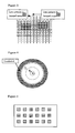
- Figure 1 shows an alternative to the above described polarization filtering method.
- This method comprises dynamic complementary lighting/scanning of alternating patterned image sections. This method does not require the use of polarization filters. It is based on the fact that photons entering biological tissue will strongly scatter within the tissue which partly results in backscattering.
- line sections Furthermore the viewed area is divided into parallel linear areas , which we will call “line sections”. These line sections can be divided into even and uneven line sections 1, 2 respectively.
- the bounded light source will light all even line sections 1 and the camera will acquire image information from all uneven line sections 2.
- the term bounded encompasses light that is bounded spatially, so that an illuminated object comprises, in a direction of view which is also a direction of illumination, non-illuminated areas which are not reached by the bounded light source. Such bounding can be typically reached by focusing, collimating or shielding the light source. Also various other light sources, such as laser lights (e.g. in combination with a holographic grating) and LEDs, can produce bounded lights.
- the uneven line sections 2 are lighted and the camera will acquire image information from the even line sections. This can either be done with a line camera that scans the entire tissue or with a normal camera that scans all even lines simultaneously and during the next period all uneven lines.
- FIG 2 is illustrated how light diffused within the tissue can be used to image deeper parts of the object.
- illumination patterns as will be further described with reference to Figure 3 - Figure 5 , illumination from "within" the object can be achieved, thus imaging deeper parts of the object.
- Figure 5 shows another embodiment, wherein said object is irradiated only at predetermined positions that are spaced apart.
- First areas 3 indicated with horizontal lines are irradiated in a first period; second areas 4 with vertical lines are irradiated in a second period.
- Such a spaced apart configuration is able to show deeper parts of the structure. By varying the spacing, lower and deeper parts of the object may be scanned.
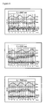
- Figure 6 shows a testing arrangement, where an embodiment of the inventive method was tested using known markers such as an SP02 pulse oximeter, an ECG recording devise and a respiratory frequency monitor.
- the signals were recorded and sampled using the steps indicated in Figure 7 . This leads to a pixel by pixel time-analysis of intensity variation.
- the frames were sampled at a 100Hz Sample rate and the recorded respiration, ECG and plethismographic pulse output were compared. The outcome is illustrated for a variety of wavelengths in Figure 8 . It is clearly shown how well the measured variation of the camera matches with the other pulse signals.
- a special configuration with added value is based upon two cameras (e.g. CCD or CMOS monochromatic or multiband) positioned at a certain distance from each other (e.g. eye-to-eye distance) thus stereoscopically viewing the same object (e.g. biological tissue), a dual channel electronic image processing device and two display devices placed in front of both eyes.
- two cameras e.g. CCD or CMOS monochromatic or multiband
- eye-to-eye distance e.g. eye-to-eye distance
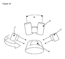
- an additional optical system (maybe combining 2 channels) may be placed (e.g., a dual channel microscope, endoscope, colposcope, etc.) It is possible to incorporate a simple vizor-like construction 5 (see Figure 9 ) so that the device can be either put in front of the eye or be positioned out of the viewing angle to allow normal sight.
- Figure 10 shows as an example the stereoscopic eyepiece 5 of Figure 9 in use.
- a color camera can be applied with a bayer color filter pattern of which all filter colors are highly transparent in the NIR-range.
- a multi-layered camera chip Patent WO 02/27804 to Foveon Inc. or earlier patents like 4,238,760 to Carr
- the approach in our previous patent WO 01 15597 A1 can be applied.
- the images in both spectral ranges match pixel to pixel.
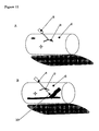
- the surface of the viewed biological tissue region 6 is irradiated at an oblique angle from two opposite sides by two light sources 7. These two sides need not to be aligned with the Left/Right axis of the eyepiece 5, but can be swiveled around in a plane perpendicular to the central axis of the joined cameras.
- the light sources 7 can be controlled to independently send out broadband white light in the visible wavelength range (VIS; 400 - 780nm) or narrowband light in the near infrared range (NIR; e.g. 920 nm) as well as in both ranges (VIS & NIR).
- the light sources 7 are carefully constructed so that the geometrical beam profiles of VIS and NIR are aligned resulting in identical shadowing in the VIS and NIR images.
- a surgical stereo microscope or an endoscopic dual channel camera (as used in stereoscopic robot surgery) with two side fiber light guides can be used to collect the images.
- Figure 11 shows the result of the VIS ( Figure 11 A) and NIR ( Figure 11 B ) images such as collected by the eyepiece 5 illustrated in Figure 10 .
- NIR and VIS beams are matched, shadows produced by irregular shapes at the tissue surface (e.g. skin structure, skin folds, molds, etc.) will also match in both wavelength ranges.
- the beams are oriented at a small angle with respect to the tissue region 6.
- skin folds etc. will produce sharp-edged shadows.
- Shiny areas that produce reflections and/or saturated pixels (marked as a star) will also match in both wavelength ranges. Due to the small angle, objects 8 that are brought towards the tissue surface 6 (e.g.
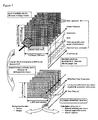
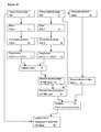
- a gradient edge enhancement step is applied for both spectral bands as will be illustrated with reference to Figure 16 (steps 13 and 14).
- Image VIS-J and NIR-J are obtained by filtering with a smoothing filter to suppress noise from camera image NIR and VIS. In the current implementation this is an averaging filter.
- two directional difference images Ix and Iy are calculated by means of a gradient filter. Currently this it performed with a Prewitt filter.
- VIS-G and NIR-G are made by Ix 2 + Iy 2 .
- VIS-G and NIR-G are clipped and normalized to 1 to obtain VIS-G' and NIR-G' (Steps 15 and 16).
- the images are complemented to 1-G' (Steps 17 and 18).
- VIS image and a pixel to pixel matching NIR image are acquired.
- the pixel coordinates that match both requirements are identified as superficial artifacts and are discarded by setting the pixel value to 1 in the corrected NIR edge image (Step 20).
- a corrected normalized NIR image (Step 22) is defined by discarding saturated image areas.
- the locations of all saturated pixels within the raw NIR image are identified.
- the edges are discarded by setting the pixel value to 1 (and thus completely ignoring edge information) is filled in, resulting in a second NIR-mask (step 23).
- This approach can be varied by including second, third etc. neighboring pixels.
- the raw IR image is used to provide "filled in” blood vessels; for example, by multiplying the 2nd NIR-mask with the 2nd corrected NIR image (step 24).
- this final enhancement mask now is multiplied with the luminosity component of the raw VIS image (which preferably is a color image) in step 25.
- the luminosity component of the raw VIS image which preferably is a color image
- the detection of purely superficial artifacts thus can be further improved when instead of taking all colors of the visible region into account, only the Blue spectral range is used for the VIS edge enhancement input. This is done in order to suppress the visibility of blood vessels. This effect of blue light is because in the visible range, the reflectivity of vessels for blue light is the nearest to skin (the maximum visible vessel contrast lies outside the blue range).
- the final enhancement mask may be selectively multiplied with e.g. only the Red and/or Green portion of the visible image (instead of the luminosity signal of the total visible color image).
- the user can switch to a mode that alters the image capturing sequence and allows the collection of an additional (second) NIR image within a selected region of interest (ROI).
- This ROI is virtually illuminated by photon injection just outside the ROI by means of EITHER a LED-array in contact with the tissue OR a pattern of laser dots or laser lines projected onto the tissue from a distance.
- EITHER a LED-array in contact with the tissue OR a pattern of laser dots or laser lines projected onto the tissue from a distance.
- the VIS and first NIR lighting are off.
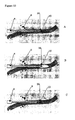
- a NIR-laser or NIR-LED is plugged onto a needle or catheter 8. Via a sterile window light is projected through or alongside the needle bore.
- the needle tip 10 illuminates the vessel interior wall 26 when the needle is in the vessel (see fig 13B ). If the needle punctures the distal vessel wall (see fig 13C ) a drastic change in illumination is seen.
- the light source clipped to the needle may be synchronized with the cameras. A flashing tip illumination may be beneficial.
Landscapes
- Health & Medical Sciences (AREA)
- Life Sciences & Earth Sciences (AREA)
- Engineering & Computer Science (AREA)
- Physics & Mathematics (AREA)
- Public Health (AREA)
- Medical Informatics (AREA)
- Veterinary Medicine (AREA)
- General Health & Medical Sciences (AREA)
- Animal Behavior & Ethology (AREA)
- Biophysics (AREA)
- Pathology (AREA)
- Biomedical Technology (AREA)
- Heart & Thoracic Surgery (AREA)
- Surgery (AREA)
- Molecular Biology (AREA)
- Theoretical Computer Science (AREA)
- General Physics & Mathematics (AREA)
- Computer Vision & Pattern Recognition (AREA)
- Radiology & Medical Imaging (AREA)
- Nuclear Medicine, Radiotherapy & Molecular Imaging (AREA)
- Vascular Medicine (AREA)
- Investigating Or Analysing Materials By Optical Means (AREA)
- Credit Cards Or The Like (AREA)
- Holo Graphy (AREA)
Claims (18)
- Verfahren, um ein Bild von verborgenen Strukturen (8) in einem Objekt zu erhalten, mit:- Bereitstellen einer Kamera (5) zur Bildaufnahme von visuellen Bildern und Infrarot-Bildern;- Bereitstellen einer begrenzten Infrarot-Lichtquelle;- teilweise Bestrahlen des Objekts mit der begrenzten Lichtquelle;- Aufnehmen eines Bildes von einem nicht-bestrahlten Gebiet (2) des Objekts mit der Kamera, um die verborgene Struktur aufzunehmen; und- Kombinieren des Bildes von der verborgenen Struktur mit einem visuellen Bild des Objekts;- Ausrichten der Infrarot-Lichtquelle mit einer visuellen Lichtquelle (7);dadurch gekennzeichnet, dass das Verfahren ferner umfasst:- Durchführen einer ersten Kantenanalyse des Infrarot-Bildes;- Durchführen einer zweiten Kantenanalyse des visuellen Bildes;- Vergleichen der ersten und der zweiten Kantenanalyse; und- Löschen der Kanten in dem Infrarot-Bild, die auch in dem zweiten Bild erfasst werden.
- Verfahren nach Anspruch 1, bei dem die Bestrahlung zeitlich so variiert wird, um ein vollständiges Bild durch aufeinanderfolgendes Kombinieren von Teilbildern zur Verfügung zu stellen.
- Verfahren nach Anspruch 1 oder 2, bei dem das Bild durch Scannen des Objekts mit einem Lichtstrahl erhalten wird.
- Verfahren nach Anspruch 1 oder 2, bei dem das Bild durch aufeinanderfolgendes Bestrahlen des Objekts mit zuvor bestimmten Mustern (1, 2) erhalten wird.
- Verfahren nach Anspruch 4, bei dem das Teilbild durch abwechselndes Bestrahlen des Objekts mit den zuvor bestimmten komplementären Mustern erhalten wird.
- Verfahren nach Anspruch 4 oder 5, bei dem die Muster Matrix-Muster, Linien-Muster, Punkt-Muster oder konzentrische Muster (T2, T2, T3) sind.
- Verfahren nach einem der Ansprüche 4-6, bei dem das Objekt bei zuvor bestimmten Positionen bestrahlt wird, die voneinander beabstandet sind.
- Verfahren nach einem der Ansprüche 1-7, bei dem das Bild durch eine CMOS-Kamera erzeugt wird.
- Verfahren nach Anspruch 1, außerdem mit:- Korrigieren des ersten Bildes, um gesättigte Bildgebiete zu löschen.
- Verfahren nach einem der vorhergehenden Ansprüche, bei dem die Bilder stereoskopisch erhalten werden.
- Verfahren nach einem der vorhergehenden Ansprüche, bei dem das erste Bild spektral analysiert wird und bei dem diese spektrale Analyse in das zweite Bild projiziert wird.
- Verfahren nach Anspruch 11, bei dem die spektrale Analyse eine Pulsatilitätsanalyse und/oder ein Herzschlagfrequenzanalyse und/oder eine Atmungsfrequenzanalyse umfasst.
- System, um ein Bild von verborgenen Strukturen in einem Objekt zu erhalten, mit:- einer begrenzten Infrarot-Lichtquelle (7), wobei die Lichtquelle mit einer visuellen Lichtquelle (7) ausgerichtet ist, um das Objekt teilweise mit Licht zu bestrahlen;- einer Kameravorrichtung (5), die ausgestaltet ist, um ein erstes Bild von verborgenen Strukturen in einem nicht-bestrahlten Gebiet des Objekts zu erhalten und um ein zweites visuelles Bild des Objekts zu erhalten; und- einer Verarbeitungsvorrichtung, die ausgestaltet ist, um:- eine Gradientenanalyse des ersten Bildes von verborgenen Strukturen zur Verfügung zu stellen, um die Kanten der verborgenen Struktur zu erfassen; und um eine Gradientenanalyse des zweiten visuellen Bildes zur Verfügung zu stellen;- die Gradientenanalyse des zweiten visuellen Bildes mit der Gradientenanalyse des ersten Bildes von verborgenen Strukturen zu vergleichen;- Kanten in dem ersten Bild von verborgenen Strukturen zu löschen, die auch in dem zweiten visuellen Bild erfasst werden; und- das erste und das zweite Bild zu kombinieren, um Kanten der verborgenen Struktur in dem visuellen Bild zu definieren.
- System nach Anspruch 13, außerdem mit:- ein Punktionswerkzeug (8) zum Punktieren von menschlichem Gewebe; und- einer IR-Lichtquelle (10), die in dem Punktionswerkzeug vorgesehen ist.
- System nach Anspruch 14, bei dem das IR-Licht entlang des Punktionswerkzeugs ausgerichtet ist.
- System nach Anspruch 14 oder 15, bei dem das IR-Licht in einer Spitze des Punktionswerkzeugs vorgesehen ist.
- System nach einem der Ansprüche 14-16, bei dem das Punktionswerkzeug mit einer IR-Abstrahlbeschichtung versehen ist.
- System nach einem der Ansprüche 14-17, bei dem die IR-Lichtquelle und die begrenzte Lichtquelle alternativ aktiviert werden.
Priority Applications (1)
| Application Number | Priority Date | Filing Date | Title |
|---|---|---|---|
| EP05710889A EP1729629B1 (de) | 2004-02-19 | 2005-02-15 | Bilddarstellung von verborgenen strukturen |
Applications Claiming Priority (3)
| Application Number | Priority Date | Filing Date | Title |
|---|---|---|---|
| EP04075541A EP1566142A1 (de) | 2004-02-19 | 2004-02-19 | Darstellung verdeckter Objekte |
| EP05710889A EP1729629B1 (de) | 2004-02-19 | 2005-02-15 | Bilddarstellung von verborgenen strukturen |
| PCT/NL2005/000108 WO2005079662A1 (en) | 2004-02-19 | 2005-02-15 | Imaging of buried structures |
Publications (2)
| Publication Number | Publication Date |
|---|---|
| EP1729629A1 EP1729629A1 (de) | 2006-12-13 |
| EP1729629B1 true EP1729629B1 (de) | 2009-11-11 |
Family
ID=34707381
Family Applications (2)
| Application Number | Title | Priority Date | Filing Date |
|---|---|---|---|
| EP04075541A Withdrawn EP1566142A1 (de) | 2004-02-19 | 2004-02-19 | Darstellung verdeckter Objekte |
| EP05710889A Expired - Lifetime EP1729629B1 (de) | 2004-02-19 | 2005-02-15 | Bilddarstellung von verborgenen strukturen |
Family Applications Before (1)
| Application Number | Title | Priority Date | Filing Date |
|---|---|---|---|
| EP04075541A Withdrawn EP1566142A1 (de) | 2004-02-19 | 2004-02-19 | Darstellung verdeckter Objekte |
Country Status (7)
| Country | Link |
|---|---|
| US (1) | US8630465B2 (de) |
| EP (2) | EP1566142A1 (de) |
| JP (1) | JP4739242B2 (de) |
| AT (1) | ATE447880T1 (de) |
| DE (1) | DE602005017588D1 (de) |
| ES (1) | ES2336577T3 (de) |
| WO (1) | WO2005079662A1 (de) |
Families Citing this family (47)
| Publication number | Priority date | Publication date | Assignee | Title |
|---|---|---|---|---|
| US8620410B2 (en) | 2002-03-12 | 2013-12-31 | Beth Israel Deaconess Medical Center | Multi-channel medical imaging system |
| WO2003100925A2 (en) | 2002-05-22 | 2003-12-04 | Beth Israel Deaconess Medical Center | Device for wavelength-selective imaging |
| WO2005034747A1 (en) | 2003-09-15 | 2005-04-21 | Beth Israel Deaconess Medical Center | Medical imaging systems |
| US9750425B2 (en) * | 2004-03-23 | 2017-09-05 | Dune Medical Devices Ltd. | Graphical user interfaces (GUI), methods and apparatus for data presentation |
| US20060241495A1 (en) * | 2005-03-23 | 2006-10-26 | Eastman Kodak Company | Wound healing monitoring and treatment |
| US8478386B2 (en) | 2006-01-10 | 2013-07-02 | Accuvein Inc. | Practitioner-mounted micro vein enhancer |
| US9854977B2 (en) | 2006-01-10 | 2018-01-02 | Accuvein, Inc. | Scanned laser vein contrast enhancer using a single laser, and modulation circuitry |
| US12295744B2 (en) | 2006-01-10 | 2025-05-13 | Accuvein, Inc. | Micro vein enhancer with two lasers and two optical detectors configured for removing surface topology |
| US8489178B2 (en) | 2006-06-29 | 2013-07-16 | Accuvein Inc. | Enhanced laser vein contrast enhancer with projection of analyzed vein data |
| US12089951B2 (en) | 2006-01-10 | 2024-09-17 | AccuVeiw, Inc. | Scanned laser vein contrast enhancer with scanning correlated to target distance |
| US12471844B2 (en) | 2006-06-29 | 2025-11-18 | Accuvein, Inc. | Scanned laser vein contrast enhancer with full stopping of scanner movement during scan line reversals |
| US8838210B2 (en) | 2006-06-29 | 2014-09-16 | AccuView, Inc. | Scanned laser vein contrast enhancer using a single laser |
| US10813588B2 (en) | 2006-01-10 | 2020-10-27 | Accuvein, Inc. | Micro vein enhancer |
| US9492117B2 (en) | 2006-01-10 | 2016-11-15 | Accuvein, Inc. | Practitioner-mounted micro vein enhancer |
| US11253198B2 (en) | 2006-01-10 | 2022-02-22 | Accuvein, Inc. | Stand-mounted scanned laser vein contrast enhancer |
| US10238294B2 (en) | 2006-06-29 | 2019-03-26 | Accuvein, Inc. | Scanned laser vein contrast enhancer using one laser |
| US11278240B2 (en) | 2006-01-10 | 2022-03-22 | Accuvein, Inc. | Trigger-actuated laser vein contrast enhancer |
| US12408865B2 (en) | 2006-01-10 | 2025-09-09 | Accuvein Inc. | Vein imaging device with differential image resolution at the center and the extremities of the vein image |
| CN101427125B (zh) | 2006-04-18 | 2011-09-14 | 皇家飞利浦电子股份有限公司 | 光学测量设备 |
| US8463364B2 (en) | 2009-07-22 | 2013-06-11 | Accuvein Inc. | Vein scanner |
| US8594770B2 (en) | 2006-06-29 | 2013-11-26 | Accuvein, Inc. | Multispectral detection and presentation of an object's characteristics |
| US8730321B2 (en) | 2007-06-28 | 2014-05-20 | Accuvein, Inc. | Automatic alignment of a contrast enhancement system |
| JP5073996B2 (ja) * | 2006-09-20 | 2012-11-14 | オリンパス株式会社 | 画像処理装置 |
| IL180469A0 (en) * | 2006-12-31 | 2007-06-03 | Gil Shetrit | Vascular access system and method |
| JP5594788B2 (ja) * | 2008-12-05 | 2014-09-24 | アケソ メディカル イメージング ビー. ヴィ. | 関節の状態の光学的検出方法及び光学的検出用装置 |
| US8503712B2 (en) * | 2008-12-31 | 2013-08-06 | Motorola Mobility Llc | Method and apparatus for determining blood oxygenation using a mobile communication device |
| NL2002544C2 (en) * | 2009-02-18 | 2010-08-19 | Bio Photonics Holding B V | Pixel-to-pixel aligned multispectral imaging & spatial light modulation through optical instruments. |
| US9061109B2 (en) | 2009-07-22 | 2015-06-23 | Accuvein, Inc. | Vein scanner with user interface |
| FR2969292A1 (fr) | 2010-12-17 | 2012-06-22 | Commissariat Energie Atomique | Procede et dispositif pour examen optique en geometrie de reflexion |
| WO2012168322A2 (en) | 2011-06-06 | 2012-12-13 | 3Shape A/S | Dual-resolution 3d scanner |
| US8879848B2 (en) * | 2011-07-27 | 2014-11-04 | National Instruments Corporation | Machine vision based automatic maximal clamp measurement tool |
| JP6590438B2 (ja) * | 2012-03-13 | 2019-10-16 | コーニンクレッカ フィリップス エヌ ヴェKoninklijke Philips N.V. | 生理学的センサを有する心肺蘇生装置 |
| US8897522B2 (en) * | 2012-05-30 | 2014-11-25 | Xerox Corporation | Processing a video for vascular pattern detection and cardiac function analysis |
| US9072426B2 (en) | 2012-08-02 | 2015-07-07 | AccuVein, Inc | Device for detecting and illuminating vasculature using an FPGA |
| US10517483B2 (en) | 2012-12-05 | 2019-12-31 | Accuvein, Inc. | System for detecting fluorescence and projecting a representative image |
| CN203289635U (zh) | 2013-05-10 | 2013-11-13 | 瑞声声学科技(深圳)有限公司 | 弹簧板及应用该弹簧板的多功能发声器 |
| JP6261994B2 (ja) * | 2014-01-28 | 2018-01-17 | 三菱重工業株式会社 | 画像補正方法、これを用いる検査方法及び検査装置 |
| US9990730B2 (en) | 2014-03-21 | 2018-06-05 | Fluke Corporation | Visible light image with edge marking for enhancing IR imagery |
| JP6511777B2 (ja) * | 2014-11-10 | 2019-05-15 | セイコーエプソン株式会社 | 画像処理装置、画像処理方法およびプログラム |
| CN112932416A (zh) * | 2015-06-04 | 2021-06-11 | 松下知识产权经营株式会社 | 生物体信息检测装置及生物体信息检测方法 |
| US10152811B2 (en) | 2015-08-27 | 2018-12-11 | Fluke Corporation | Edge enhancement for thermal-visible combined images and cameras |
| CN114795151A (zh) * | 2016-06-30 | 2022-07-29 | 松下知识产权经营株式会社 | 方法及系统 |
| CN116269262A (zh) * | 2016-12-01 | 2023-06-23 | 松下知识产权经营株式会社 | 生物体信息检测装置、生物体信息检测方法及存储介质 |
| TWI662940B (zh) * | 2018-06-01 | 2019-06-21 | 廣達電腦股份有限公司 | 影像擷取裝置 |
| JP7247501B2 (ja) * | 2018-09-21 | 2023-03-29 | 富士フイルムビジネスイノベーション株式会社 | 画像処理装置およびプログラム |
| NL2023688B1 (en) | 2019-08-22 | 2021-04-21 | I Med Tech B V | Binocular device |
| CN111879791B (zh) * | 2020-07-30 | 2023-06-20 | 西湖大学 | 一种图案表面凸起特征增强的机器视觉系统及方法 |
Family Cites Families (12)
| Publication number | Priority date | Publication date | Assignee | Title |
|---|---|---|---|---|
| US4555179A (en) * | 1982-11-08 | 1985-11-26 | John Langerholc | Detection and imaging of objects in scattering media by light irradiation |
| US5137355A (en) * | 1988-06-08 | 1992-08-11 | The Research Foundation Of State University Of New York | Method of imaging a random medium |
| US5699797A (en) * | 1992-10-05 | 1997-12-23 | Dynamics Imaging, Inc. | Method of investigation of microcirculation functional dynamics of physiological liquids in skin and apparatus for its realization |
| US6032070A (en) * | 1995-06-07 | 2000-02-29 | University Of Arkansas | Method and apparatus for detecting electro-magnetic reflection from biological tissue |
| NL1012943C2 (nl) * | 1999-08-31 | 2001-03-01 | Tno | Detector en beeldvormende inrichting voor het bepalen van concentratieverhoudingen. |
| WO2001050955A1 (en) * | 2000-01-14 | 2001-07-19 | Flock Stephen T | Improved endoscopic imaging and treatment of anatomic structures |
| WO2001052735A1 (de) * | 2000-01-17 | 2001-07-26 | Stiftung Zur Förderung Der Erforschung Und Behandlung Kindlicher Leukämien (Kinderleukämiestiftung) | Verbesserung der sichtbarkeit von venen-punktionsstellen |
| DE10004989B4 (de) * | 2000-02-04 | 2006-11-02 | Siemens Ag | Verfahren und Vorrichtung für die Arthritis-Diagnose |
| US20020035317A1 (en) * | 2000-08-04 | 2002-03-21 | Photonify Technologies | Optical imaging system with movable scanning unit |
| US7058233B2 (en) * | 2001-05-30 | 2006-06-06 | Mitutoyo Corporation | Systems and methods for constructing an image having an extended depth of field |
| US7158660B2 (en) * | 2002-05-08 | 2007-01-02 | Gee Jr James W | Method and apparatus for detecting structures of interest |
| US7372985B2 (en) * | 2003-08-15 | 2008-05-13 | Massachusetts Institute Of Technology | Systems and methods for volumetric tissue scanning microscopy |
-
2004
- 2004-02-19 EP EP04075541A patent/EP1566142A1/de not_active Withdrawn
-
2005
- 2005-02-15 JP JP2006554039A patent/JP4739242B2/ja not_active Expired - Fee Related
- 2005-02-15 ES ES05710889T patent/ES2336577T3/es not_active Expired - Lifetime
- 2005-02-15 DE DE602005017588T patent/DE602005017588D1/de not_active Expired - Lifetime
- 2005-02-15 WO PCT/NL2005/000108 patent/WO2005079662A1/en not_active Ceased
- 2005-02-15 AT AT05710889T patent/ATE447880T1/de active
- 2005-02-15 US US10/598,077 patent/US8630465B2/en not_active Expired - Fee Related
- 2005-02-15 EP EP05710889A patent/EP1729629B1/de not_active Expired - Lifetime
Also Published As
| Publication number | Publication date |
|---|---|
| JP4739242B2 (ja) | 2011-08-03 |
| ES2336577T3 (es) | 2010-04-14 |
| JP2007522869A (ja) | 2007-08-16 |
| DE602005017588D1 (de) | 2009-12-24 |
| US8630465B2 (en) | 2014-01-14 |
| EP1729629A1 (de) | 2006-12-13 |
| ATE447880T1 (de) | 2009-11-15 |
| US20090028461A1 (en) | 2009-01-29 |
| WO2005079662A1 (en) | 2005-09-01 |
| EP1566142A1 (de) | 2005-08-24 |
Similar Documents
| Publication | Publication Date | Title |
|---|---|---|
| EP1729629B1 (de) | Bilddarstellung von verborgenen strukturen | |
| CN105848566B (zh) | 用于预定生物结构的无创检测的设备 | |
| US5408998A (en) | Video based tissue oximetry | |
| US6775565B1 (en) | Imaging apparatus for displaying concentration ratios | |
| JP6763719B2 (ja) | 生体情報測定装置、生体情報測定方法及びプログラム | |
| US20100061598A1 (en) | Apparatus and method for recognizing subcutaneous vein pattern | |
| US20160270665A1 (en) | Method and apparatus for imaging tissue topography | |
| US20080062429A1 (en) | Low coherence dental oct imaging | |
| JP7374280B2 (ja) | 内視鏡装置、内視鏡プロセッサ、及び内視鏡装置の作動方法 | |
| US10159418B2 (en) | Information obtaining apparatus, image capturing apparatus, and method for obtaining information | |
| CN215305781U (zh) | 识别甲状旁腺位置并评估甲状旁腺存活率的设备 | |
| EP3393341B1 (de) | Vorrichtung und verfahren zur akquisition von medizinischen bildern zur analyse von geschwüren | |
| WO2021059889A1 (ja) | 内視鏡システム | |
| JP2012010776A (ja) | 断層画像処理装置及び方法、並びに光干渉断層画像診断装置 | |
| JP4109132B2 (ja) | 蛍光判定装置 | |
| Wieringa et al. | Pulse oxigraphy demonstrated on a phantom with arterial and venous regions | |
| Awais et al. | Analysis of auto-fluorescence images for automatic detection of abnormalities in oral cavity | |
| CN113424048A (zh) | 组织检测系统及其使用方法 | |
| CN114041737B (zh) | 应用于内窥镜的成像装置 | |
| KR101669411B1 (ko) | 피부 및 치아 검사 시스템 및 방법 | |
| JP2012050598A (ja) | 撮像表示方法および装置 | |
| CN118806231A (zh) | 一种带显示屏的皮肤检测装置 | |
| KR101047902B1 (ko) | 피부 상태 측정 장치 | |
| AU2014338605A1 (en) | Device for non-invasive detection of predetermined biological structures |
Legal Events
| Date | Code | Title | Description |
|---|---|---|---|
| PUAI | Public reference made under article 153(3) epc to a published international application that has entered the european phase |
Free format text: ORIGINAL CODE: 0009012 |
|
| 17P | Request for examination filed |
Effective date: 20060904 |
|
| AK | Designated contracting states |
Kind code of ref document: A1 Designated state(s): AT BE BG CH CY CZ DE DK EE ES FI FR GB GR HU IE IS IT LI LT LU MC NL PL PT RO SE SI SK TR |
|
| 17Q | First examination report despatched |
Effective date: 20061211 |
|
| DAX | Request for extension of the european patent (deleted) | ||
| GRAP | Despatch of communication of intention to grant a patent |
Free format text: ORIGINAL CODE: EPIDOSNIGR1 |
|
| GRAS | Grant fee paid |
Free format text: ORIGINAL CODE: EPIDOSNIGR3 |
|
| GRAA | (expected) grant |
Free format text: ORIGINAL CODE: 0009210 |
|
| AK | Designated contracting states |
Kind code of ref document: B1 Designated state(s): AT BE BG CH CY CZ DE DK EE ES FI FR GB GR HU IE IS IT LI LT LU MC NL PL PT RO SE SI SK TR |
|
| REG | Reference to a national code |
Ref country code: GB Ref legal event code: FG4D |
|
| REG | Reference to a national code |
Ref country code: CH Ref legal event code: EP |
|
| REG | Reference to a national code |
Ref country code: IE Ref legal event code: FG4D |
|
| REF | Corresponds to: |
Ref document number: 602005017588 Country of ref document: DE Date of ref document: 20091224 Kind code of ref document: P |
|
| REG | Reference to a national code |
Ref country code: SE Ref legal event code: TRGR |
|
| REG | Reference to a national code |
Ref country code: CH Ref legal event code: NV Representative=s name: PATENTANWAELTE SCHAAD, BALASS, MENZL & PARTNER AG |
|
| REG | Reference to a national code |
Ref country code: ES Ref legal event code: FG2A Ref document number: 2336577 Country of ref document: ES Kind code of ref document: T3 |
|
| LTIE | Lt: invalidation of european patent or patent extension |
Effective date: 20091111 |
|
| PG25 | Lapsed in a contracting state [announced via postgrant information from national office to epo] |
Ref country code: PT Free format text: LAPSE BECAUSE OF FAILURE TO SUBMIT A TRANSLATION OF THE DESCRIPTION OR TO PAY THE FEE WITHIN THE PRESCRIBED TIME-LIMIT Effective date: 20100311 Ref country code: IS Free format text: LAPSE BECAUSE OF FAILURE TO SUBMIT A TRANSLATION OF THE DESCRIPTION OR TO PAY THE FEE WITHIN THE PRESCRIBED TIME-LIMIT Effective date: 20100311 Ref country code: LT Free format text: LAPSE BECAUSE OF FAILURE TO SUBMIT A TRANSLATION OF THE DESCRIPTION OR TO PAY THE FEE WITHIN THE PRESCRIBED TIME-LIMIT Effective date: 20091111 |
|
| PG25 | Lapsed in a contracting state [announced via postgrant information from national office to epo] |
Ref country code: SI Free format text: LAPSE BECAUSE OF FAILURE TO SUBMIT A TRANSLATION OF THE DESCRIPTION OR TO PAY THE FEE WITHIN THE PRESCRIBED TIME-LIMIT Effective date: 20091111 Ref country code: PL Free format text: LAPSE BECAUSE OF FAILURE TO SUBMIT A TRANSLATION OF THE DESCRIPTION OR TO PAY THE FEE WITHIN THE PRESCRIBED TIME-LIMIT Effective date: 20091111 Ref country code: CY Free format text: LAPSE BECAUSE OF FAILURE TO SUBMIT A TRANSLATION OF THE DESCRIPTION OR TO PAY THE FEE WITHIN THE PRESCRIBED TIME-LIMIT Effective date: 20091111 |
|
| PG25 | Lapsed in a contracting state [announced via postgrant information from national office to epo] |
Ref country code: RO Free format text: LAPSE BECAUSE OF FAILURE TO SUBMIT A TRANSLATION OF THE DESCRIPTION OR TO PAY THE FEE WITHIN THE PRESCRIBED TIME-LIMIT Effective date: 20091111 Ref country code: EE Free format text: LAPSE BECAUSE OF FAILURE TO SUBMIT A TRANSLATION OF THE DESCRIPTION OR TO PAY THE FEE WITHIN THE PRESCRIBED TIME-LIMIT Effective date: 20091111 Ref country code: DK Free format text: LAPSE BECAUSE OF FAILURE TO SUBMIT A TRANSLATION OF THE DESCRIPTION OR TO PAY THE FEE WITHIN THE PRESCRIBED TIME-LIMIT Effective date: 20091111 Ref country code: BG Free format text: LAPSE BECAUSE OF FAILURE TO SUBMIT A TRANSLATION OF THE DESCRIPTION OR TO PAY THE FEE WITHIN THE PRESCRIBED TIME-LIMIT Effective date: 20100211 |
|
| PG25 | Lapsed in a contracting state [announced via postgrant information from national office to epo] |
Ref country code: CZ Free format text: LAPSE BECAUSE OF FAILURE TO SUBMIT A TRANSLATION OF THE DESCRIPTION OR TO PAY THE FEE WITHIN THE PRESCRIBED TIME-LIMIT Effective date: 20091111 Ref country code: SK Free format text: LAPSE BECAUSE OF FAILURE TO SUBMIT A TRANSLATION OF THE DESCRIPTION OR TO PAY THE FEE WITHIN THE PRESCRIBED TIME-LIMIT Effective date: 20091111 |
|
| PLBE | No opposition filed within time limit |
Free format text: ORIGINAL CODE: 0009261 |
|
| STAA | Information on the status of an ep patent application or granted ep patent |
Free format text: STATUS: NO OPPOSITION FILED WITHIN TIME LIMIT |
|
| 26N | No opposition filed |
Effective date: 20100812 |
|
| PG25 | Lapsed in a contracting state [announced via postgrant information from national office to epo] |
Ref country code: MC Free format text: LAPSE BECAUSE OF NON-PAYMENT OF DUE FEES Effective date: 20100301 Ref country code: GR Free format text: LAPSE BECAUSE OF FAILURE TO SUBMIT A TRANSLATION OF THE DESCRIPTION OR TO PAY THE FEE WITHIN THE PRESCRIBED TIME-LIMIT Effective date: 20100212 |
|
| PG25 | Lapsed in a contracting state [announced via postgrant information from national office to epo] |
Ref country code: LU Free format text: LAPSE BECAUSE OF NON-PAYMENT OF DUE FEES Effective date: 20100215 Ref country code: HU Free format text: LAPSE BECAUSE OF FAILURE TO SUBMIT A TRANSLATION OF THE DESCRIPTION OR TO PAY THE FEE WITHIN THE PRESCRIBED TIME-LIMIT Effective date: 20100512 |
|
| PG25 | Lapsed in a contracting state [announced via postgrant information from national office to epo] |
Ref country code: TR Free format text: LAPSE BECAUSE OF FAILURE TO SUBMIT A TRANSLATION OF THE DESCRIPTION OR TO PAY THE FEE WITHIN THE PRESCRIBED TIME-LIMIT Effective date: 20091111 |
|
| PGFP | Annual fee paid to national office [announced via postgrant information from national office to epo] |
Ref country code: NL Payment date: 20140218 Year of fee payment: 10 Ref country code: SE Payment date: 20140218 Year of fee payment: 10 Ref country code: FI Payment date: 20140212 Year of fee payment: 10 Ref country code: IE Payment date: 20140221 Year of fee payment: 10 Ref country code: CH Payment date: 20140218 Year of fee payment: 10 |
|
| PGFP | Annual fee paid to national office [announced via postgrant information from national office to epo] |
Ref country code: AT Payment date: 20140212 Year of fee payment: 10 Ref country code: IT Payment date: 20140226 Year of fee payment: 10 Ref country code: BE Payment date: 20140218 Year of fee payment: 10 Ref country code: ES Payment date: 20140226 Year of fee payment: 10 |
|
| PG25 | Lapsed in a contracting state [announced via postgrant information from national office to epo] |
Ref country code: BE Free format text: LAPSE BECAUSE OF NON-PAYMENT OF DUE FEES Effective date: 20150228 |
|
| REG | Reference to a national code |
Ref country code: NL Ref legal event code: V1 Effective date: 20150901 |
|
| REG | Reference to a national code |
Ref country code: SE Ref legal event code: EUG |
|
| PG25 | Lapsed in a contracting state [announced via postgrant information from national office to epo] |
Ref country code: NL Free format text: LAPSE BECAUSE OF NON-PAYMENT OF DUE FEES Effective date: 20150901 |
|
| REG | Reference to a national code |
Ref country code: CH Ref legal event code: PL |
|
| REG | Reference to a national code |
Ref country code: AT Ref legal event code: MM01 Ref document number: 447880 Country of ref document: AT Kind code of ref document: T Effective date: 20150215 |
|
| PG25 | Lapsed in a contracting state [announced via postgrant information from national office to epo] |
Ref country code: LI Free format text: LAPSE BECAUSE OF NON-PAYMENT OF DUE FEES Effective date: 20150228 Ref country code: FI Free format text: LAPSE BECAUSE OF NON-PAYMENT OF DUE FEES Effective date: 20150215 Ref country code: CH Free format text: LAPSE BECAUSE OF NON-PAYMENT OF DUE FEES Effective date: 20150228 |
|
| REG | Reference to a national code |
Ref country code: IE Ref legal event code: MM4A |
|
| PG25 | Lapsed in a contracting state [announced via postgrant information from national office to epo] |
Ref country code: AT Free format text: LAPSE BECAUSE OF NON-PAYMENT OF DUE FEES Effective date: 20150215 Ref country code: SE Free format text: LAPSE BECAUSE OF NON-PAYMENT OF DUE FEES Effective date: 20150216 |
|
| PG25 | Lapsed in a contracting state [announced via postgrant information from national office to epo] |
Ref country code: IT Free format text: LAPSE BECAUSE OF NON-PAYMENT OF DUE FEES Effective date: 20150215 |
|
| PG25 | Lapsed in a contracting state [announced via postgrant information from national office to epo] |
Ref country code: IE Free format text: LAPSE BECAUSE OF NON-PAYMENT OF DUE FEES Effective date: 20150215 |
|
| REG | Reference to a national code |
Ref country code: FR Ref legal event code: PLFP Year of fee payment: 12 |
|
| REG | Reference to a national code |
Ref country code: ES Ref legal event code: FD2A Effective date: 20160603 |
|
| PG25 | Lapsed in a contracting state [announced via postgrant information from national office to epo] |
Ref country code: ES Free format text: LAPSE BECAUSE OF NON-PAYMENT OF DUE FEES Effective date: 20150216 |
|
| REG | Reference to a national code |
Ref country code: FR Ref legal event code: PLFP Year of fee payment: 13 |
|
| REG | Reference to a national code |
Ref country code: FR Ref legal event code: PLFP Year of fee payment: 14 |
|
| PGFP | Annual fee paid to national office [announced via postgrant information from national office to epo] |
Ref country code: DE Payment date: 20190219 Year of fee payment: 15 Ref country code: GB Payment date: 20190218 Year of fee payment: 15 |
|
| PGFP | Annual fee paid to national office [announced via postgrant information from national office to epo] |
Ref country code: FR Payment date: 20190220 Year of fee payment: 15 |
|
| REG | Reference to a national code |
Ref country code: DE Ref legal event code: R119 Ref document number: 602005017588 Country of ref document: DE |
|
| GBPC | Gb: european patent ceased through non-payment of renewal fee |
Effective date: 20200215 |
|
| PG25 | Lapsed in a contracting state [announced via postgrant information from national office to epo] |
Ref country code: FR Free format text: LAPSE BECAUSE OF NON-PAYMENT OF DUE FEES Effective date: 20200229 Ref country code: GB Free format text: LAPSE BECAUSE OF NON-PAYMENT OF DUE FEES Effective date: 20200215 Ref country code: DE Free format text: LAPSE BECAUSE OF NON-PAYMENT OF DUE FEES Effective date: 20200901 |