EP1729609B1 - Produits de fixation a effleurement - Google Patents
Produits de fixation a effleurement Download PDFInfo
- Publication number
- EP1729609B1 EP1729609B1 EP05764674A EP05764674A EP1729609B1 EP 1729609 B1 EP1729609 B1 EP 1729609B1 EP 05764674 A EP05764674 A EP 05764674A EP 05764674 A EP05764674 A EP 05764674A EP 1729609 B1 EP1729609 B1 EP 1729609B1
- Authority
- EP
- European Patent Office
- Prior art keywords
- selvedges
- base
- central portion
- fastener
- trench
- Prior art date
- Legal status (The legal status is an assumption and is not a legal conclusion. Google has not performed a legal analysis and makes no representation as to the accuracy of the status listed.)
- Not-in-force
Links
- 239000006260 foam Substances 0.000 claims abstract description 57
- 229920005989 resin Polymers 0.000 claims abstract description 28
- 239000011347 resin Substances 0.000 claims abstract description 28
- 239000000463 material Substances 0.000 claims description 51
- 238000000034 method Methods 0.000 claims description 19
- 239000004952 Polyamide Substances 0.000 claims description 9
- 229920002647 polyamide Polymers 0.000 claims description 9
- 239000002184 metal Substances 0.000 claims description 8
- 229910052751 metal Inorganic materials 0.000 claims description 8
- 239000011248 coating agent Substances 0.000 claims description 5
- 238000000576 coating method Methods 0.000 claims description 5
- 239000000203 mixture Substances 0.000 claims description 4
- 239000004831 Hot glue Substances 0.000 claims description 3
- 230000001154 acute effect Effects 0.000 claims description 3
- 239000002245 particle Substances 0.000 claims description 3
- 229920005749 polyurethane resin Polymers 0.000 claims description 2
- 238000000465 moulding Methods 0.000 abstract description 11
- 238000005187 foaming Methods 0.000 abstract description 4
- 238000006243 chemical reaction Methods 0.000 abstract description 3
- 239000000853 adhesive Substances 0.000 description 9
- 230000001070 adhesive effect Effects 0.000 description 9
- 239000004744 fabric Substances 0.000 description 7
- XEEYBQQBJWHFJM-UHFFFAOYSA-N Iron Chemical compound [Fe] XEEYBQQBJWHFJM-UHFFFAOYSA-N 0.000 description 6
- 238000005452 bending Methods 0.000 description 4
- 239000007788 liquid Substances 0.000 description 4
- 239000012943 hotmelt Substances 0.000 description 3
- 229910052742 iron Inorganic materials 0.000 description 3
- 239000004677 Nylon Substances 0.000 description 2
- 239000004743 Polypropylene Substances 0.000 description 2
- 238000004519 manufacturing process Methods 0.000 description 2
- 229920001778 nylon Polymers 0.000 description 2
- 239000000123 paper Substances 0.000 description 2
- 229920000728 polyester Polymers 0.000 description 2
- -1 polypropylene Polymers 0.000 description 2
- 229920001155 polypropylene Polymers 0.000 description 2
- 229920002635 polyurethane Polymers 0.000 description 2
- 239000004814 polyurethane Substances 0.000 description 2
- 229920000742 Cotton Polymers 0.000 description 1
- 229920005830 Polyurethane Foam Polymers 0.000 description 1
- 229910000831 Steel Inorganic materials 0.000 description 1
- 239000002313 adhesive film Substances 0.000 description 1
- 239000011324 bead Substances 0.000 description 1
- 238000010276 construction Methods 0.000 description 1
- 238000005336 cracking Methods 0.000 description 1
- 230000032798 delamination Effects 0.000 description 1
- 230000000694 effects Effects 0.000 description 1
- 229920001971 elastomer Polymers 0.000 description 1
- 238000001125 extrusion Methods 0.000 description 1
- 239000000835 fiber Substances 0.000 description 1
- 239000002657 fibrous material Substances 0.000 description 1
- 238000012986 modification Methods 0.000 description 1
- 230000004048 modification Effects 0.000 description 1
- 239000011496 polyurethane foam Substances 0.000 description 1
- 238000003825 pressing Methods 0.000 description 1
- 238000007789 sealing Methods 0.000 description 1
- 238000000926 separation method Methods 0.000 description 1
- 239000010959 steel Substances 0.000 description 1
Images


Classifications
-
- A—HUMAN NECESSITIES
- A44—HABERDASHERY; JEWELLERY
- A44B—BUTTONS, PINS, BUCKLES, SLIDE FASTENERS, OR THE LIKE
- A44B18/00—Fasteners of the touch-and-close type; Making such fasteners
- A44B18/0069—Details
- A44B18/0076—Adaptations for being fixed to a moulded article during moulding
-
- Y—GENERAL TAGGING OF NEW TECHNOLOGICAL DEVELOPMENTS; GENERAL TAGGING OF CROSS-SECTIONAL TECHNOLOGIES SPANNING OVER SEVERAL SECTIONS OF THE IPC; TECHNICAL SUBJECTS COVERED BY FORMER USPC CROSS-REFERENCE ART COLLECTIONS [XRACs] AND DIGESTS
- Y10—TECHNICAL SUBJECTS COVERED BY FORMER USPC
- Y10S—TECHNICAL SUBJECTS COVERED BY FORMER USPC CROSS-REFERENCE ART COLLECTIONS [XRACs] AND DIGESTS
- Y10S428/00—Stock material or miscellaneous articles
- Y10S428/90—Magnetic feature
-
- Y—GENERAL TAGGING OF NEW TECHNOLOGICAL DEVELOPMENTS; GENERAL TAGGING OF CROSS-SECTIONAL TECHNOLOGIES SPANNING OVER SEVERAL SECTIONS OF THE IPC; TECHNICAL SUBJECTS COVERED BY FORMER USPC CROSS-REFERENCE ART COLLECTIONS [XRACs] AND DIGESTS
- Y10—TECHNICAL SUBJECTS COVERED BY FORMER USPC
- Y10T—TECHNICAL SUBJECTS COVERED BY FORMER US CLASSIFICATION
- Y10T24/00—Buckles, buttons, clasps, etc.
- Y10T24/27—Buckles, buttons, clasps, etc. including readily dissociable fastener having numerous, protruding, unitary filaments randomly interlocking with, and simultaneously moving towards, mating structure [e.g., hook-loop type fastener]
- Y10T24/2708—Combined with diverse fastener
-
- Y—GENERAL TAGGING OF NEW TECHNOLOGICAL DEVELOPMENTS; GENERAL TAGGING OF CROSS-SECTIONAL TECHNOLOGIES SPANNING OVER SEVERAL SECTIONS OF THE IPC; TECHNICAL SUBJECTS COVERED BY FORMER USPC CROSS-REFERENCE ART COLLECTIONS [XRACs] AND DIGESTS
- Y10—TECHNICAL SUBJECTS COVERED BY FORMER USPC
- Y10T—TECHNICAL SUBJECTS COVERED BY FORMER US CLASSIFICATION
- Y10T428/00—Stock material or miscellaneous articles
- Y10T428/24—Structurally defined web or sheet [e.g., overall dimension, etc.]
- Y10T428/24008—Structurally defined web or sheet [e.g., overall dimension, etc.] including fastener for attaching to external surface
- Y10T428/24017—Hook or barb
-
- Y—GENERAL TAGGING OF NEW TECHNOLOGICAL DEVELOPMENTS; GENERAL TAGGING OF CROSS-SECTIONAL TECHNOLOGIES SPANNING OVER SEVERAL SECTIONS OF THE IPC; TECHNICAL SUBJECTS COVERED BY FORMER USPC CROSS-REFERENCE ART COLLECTIONS [XRACs] AND DIGESTS
- Y10—TECHNICAL SUBJECTS COVERED BY FORMER USPC
- Y10T—TECHNICAL SUBJECTS COVERED BY FORMER US CLASSIFICATION
- Y10T428/00—Stock material or miscellaneous articles
- Y10T428/24—Structurally defined web or sheet [e.g., overall dimension, etc.]
- Y10T428/24174—Structurally defined web or sheet [e.g., overall dimension, etc.] including sheet or component perpendicular to plane of web or sheet
- Y10T428/24182—Inward from edge of web or sheet
-
- Y—GENERAL TAGGING OF NEW TECHNOLOGICAL DEVELOPMENTS; GENERAL TAGGING OF CROSS-SECTIONAL TECHNOLOGIES SPANNING OVER SEVERAL SECTIONS OF THE IPC; TECHNICAL SUBJECTS COVERED BY FORMER USPC CROSS-REFERENCE ART COLLECTIONS [XRACs] AND DIGESTS
- Y10—TECHNICAL SUBJECTS COVERED BY FORMER USPC
- Y10T—TECHNICAL SUBJECTS COVERED BY FORMER US CLASSIFICATION
- Y10T428/00—Stock material or miscellaneous articles
- Y10T428/24—Structurally defined web or sheet [e.g., overall dimension, etc.]
- Y10T428/24628—Nonplanar uniform thickness material
-
- Y—GENERAL TAGGING OF NEW TECHNOLOGICAL DEVELOPMENTS; GENERAL TAGGING OF CROSS-SECTIONAL TECHNOLOGIES SPANNING OVER SEVERAL SECTIONS OF THE IPC; TECHNICAL SUBJECTS COVERED BY FORMER USPC CROSS-REFERENCE ART COLLECTIONS [XRACs] AND DIGESTS
- Y10—TECHNICAL SUBJECTS COVERED BY FORMER USPC
- Y10T—TECHNICAL SUBJECTS COVERED BY FORMER US CLASSIFICATION
- Y10T428/00—Stock material or miscellaneous articles
- Y10T428/249921—Web or sheet containing structurally defined element or component
- Y10T428/249953—Composite having voids in a component [e.g., porous, cellular, etc.]
Definitions
- This invention relates to touch fastener products, and particularly to the use of touch fastener products as mold inserts, such as in the molding of seat foam buns and the like.
- Seats for cars and light trucks have been formed by molding a foam bun that will serve as the seat cushion, and then attaching a pre-stitched fabric cover to the foam bun.
- the fabric cover is attached to the foam bun by insert molding touch fastener products into the outer surface of the foam bun and attaching cooperating touch fastener products to an inner surface of the fabric cover.
- the fastener products are attached to the fabric cover along the seams where the cover is stitched together and held in place by the seam stitching.
- the touch fastener products allow the seat manufacturer to rapidly and semi-permanently attach the fabric cover to the foam bun by pulling the fabric cover over the foam bun and pressing the opposed touch fastener products on the foam bun and fabric cover together.
- the touch fastener products can be secured to the seat foam bun during a molding process, such as by holding the fastener products magnetically against a side of the mold cavity in which the foam bun is molded, see for example document DE 199 56 011 A .
- a molding process such as by holding the fastener products magnetically against a side of the mold cavity in which the foam bun is molded, see for example document DE 199 56 011 A .
- care must be taken to avoid fouling of the fastener elements with the liquid foamable composition used to form the seat. Fouling can occur if the liquid foaming composition leaks between the edges of the base of the touch fastener product and the mold surface into the space between the fastener elements (e.g., hooks).
- the invention features a touch fastener product for use as a mold insert.
- the product includes a base having upper faces and lower faces and a central portion disposed between lateral selvedges, the central portion having a nominal thickness, a magnetically attractable material secured to the base; and a plurality of fastener elements extending in an array from the lower face of the central portion of the base, wherein the selvedges are of a significantly lesser stiffness than the stiffness of the central portion of the base, for flexure of the selvedges to conform to a mold surface as the base of the fastener product is drawn against the mold surface by magnetic attraction of the magnetically attractable material.
- the touch fastener is formed of a single contiguous resin.
- the central portion includes a strip of a first material supporting the fastener elements, and the selvedges are formed of a second material of different composition than the first material.
- the strip of first material can have a surface integrally formed with stems of the fastener elements, or the selvedges can include regions of a film secured to the upper face of the base. The film can be secured by an adhesive such as a polyamide hot melt.
- the film can have one or more of the following properties: the film can be a polyamide film, the film can have a softening point of between about 120 and 220 degrees Fahrenheit, the film can have a nominal thickness of less than about 0.020 inch, for example about 0.010 inches or less, or about 0.005 inches or less, and the film can have a flexural rigidity of between about 1500 and 2000 mg-cm, e.g., about 1800 mg-cm.
- the nominal thickness of the central portion of the base is between about 0.002 and 0.012 inch.
- the nominal thickness of the central portion of the base is greater than a nominal thickness of the selvedges.
- the magnetically attractable material includes a metal wire, a metal strip, or a coating of magnetically attractable particles.
- the magnetically attractable material is encapsulated in a hot melt adhesive.
- each selvedge extends from the array at least about 2 millimeters, for example each selvedge extends from the array at least about 4 millimeters.
- the selvedges are of a material having a flexural rigidity of between about 1000 and 3000 mg-cm, e.g., about 1500 and 2000 mg-cm, preferably about 1800 mg-cm.
- selvedges are disposed on all sides of the central portion of the base.
- the central portion of the base includes a molded resin.
- the fastener elements are male fastener elements.
- the male fastener elements include stems integrally molded with the central portion of the base, the central portion of the base including a molded resin.
- the male fastener elements have loop-engagable heads molded at distal ends of the stems.
- the male fastener elements are hook-shaped.
- the fastener elements are arranged in a density of at least about 100 per square inch across the array.
- the fastener elements have an overall height, as measured normal to the base, of less than about 0.050 inch.
- the invention features a method of forming a seat foam bun.
- the method includes providing a mold cavity having a shape corresponding to the shape of the seat foam bun, wherein the mold cavity includes a tapered trench having angled side walls, providing a touch fastener including a base, a magnatically attractable material, and a plurality of fastener elements extending from a lower face of a central portion of the base in an array disposed between lateral selvedges of the base positioning the touch fastener along the trench with the selvedges deflected from their unloaded position to extend along the trench side walls in face-to-face contact, and delivering a foamable resin into the mold cavity to form a seat foam bun, the deflected selvedges resisting intrusion of foamable resin into the array of fastener elements.
- a lower face of the selvedges has a substantially flat surface.
- the selvedges are of a significantly lesser stiffness than a stiffness of the central portion of the base.
- the trench has flat side walls extending at acute angles (e.g., 5°, 10°, 15°, 20°, 25°, 30°, 35°, 40°, 45°, or 50°) from a bottom surface of the trench.
- the trench has curved side walls, the selvedges conforming to arcuate surfaces of the trench side walls.
- the selvedges and central portion of the base lie in a common plane, the distal edges of the selvedges deflected out of the common plane with the fastener positioned along the trench.
- the distal edges of the selvedges contact the trench side walls with the fastener positioned along the trench.
- the selvedges are disposed around all sides of the central portion of the base.
- the selvedges comprise a film, for example a polyamide.
- the film is adhered to the base, for example with a polyamide hot melt resin.
- the film has a softening point between 120 and 220 degrees Fahrenheit.
- the central portion of the base has a nominal thickness of between about 0.002 and 0.012 inch.
- the central portion of the base is thicker than the selvedges.
- the magnetically attractable material is disposed on the upper face of the central portion of the base. In some cases, the selvedges are substantially free of magnetically attractable material. In some instances, the trench overlays a magnet.
- the trench is elongated, and the fastener product is in strip form. In some embodiments, the trench is a circular plateau and the fastener product is in circular form.
- the fastener elements are male fastener elements having stems integrally molded with a surface of the central portion of the base.
- the foamable resin comprises a polyurethane resin.
- the invention features a seat foam bun.
- the seat foam bun includes a plateau disposed on a surface thereof, and positioned on the plateau is a touch fastener including a base a magnetically attractable material, and a plurality of fastener elements extending from a central portion of the base in an array disposed between selvedges of the base, wherein the selvedges are embedded in the foam and extend about opposite upper side edges of the plateau.
- the selvedges are lateral selvedges.
- the plateau is an elongated plateau. In some embodiments, the plateau is a circular plateau.
- the selvedges have a stiffness that is substantially less than a stiffness of the central portion of the base.
- the central portion of the base includes a resin.
- the selvedges include a film.
- the film has a softening point between 120 and 220 degrees Fahrenheit.
- the film is adhered to the central portion of the base.
- the central portion of the base is thicker than the selvedges.
- the selvedges extend laterally beyond the central portion at least about 2 mm.
- a magnetically attractable material is disposed on the central portion of the base.
- an exposed surface of the selvedges is substantially smooth.
- the foam is a polyurethane foam.
- stiffness refers to the resistance of a sheet-form material to bend out of its plane when subjected to a normal bending force, and is synonymous with flexural rigidity.
- touch fasteners described herein can be used in molding processes without requiring a gasket to protect the fastener elements from being fouled with foam used to form the touch fastener (for example to form a gasket), thus reducing manufacturing costs. This can eliminate an additional manufacturing step of securing a separate material
- the touch fastener products when used in a molding process, can reduce the hindrance of the flow of foamable resin during the forming of a seat foam bun. For example, by having selvedges that lie flat in face-to-face contact with a mold surface, the selvedges create only a minor ridge. Accordingly, the foamable resin can pass over the touch fastener without creating a significant disturbance in the flow of the resin (for example, as can occur when the advancing foamable resin meets an impediment), which can result in undesirable variations in foam density.
- the touch fastener By molding a touch fastener into a plateau portion of a seat form bun, with selvedges of the fastener extending over the edges of the plateau, the touch fastener can have improved adhesion to the seat form bun and be more resistant to tear.
- the improved adhesion can result from conversion of at least some normal fastener separation load into a shear force between the angled selvedges and the foam.
- the stress at the edges of the touch fasteners may be reduced.
- the selvedges can bend more easily to maintain contact with the surface of the seat foam bun in instances where the seat foam bun is subjected to a compressing stress.
- the invention features a touch fastener for use as a mold insert.
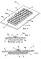
- a magnet can be positioned in a mold to position a touch fastener in a trench portion a of a flat mold surface. With to position a touch fastener 100 in a trench portion of a flat mold surface. With the fastener so positioned, a foamable liquid resin is poured into the mold cavity. An exothermic reaction occurs, causing the liquid resin to foam up to fill the cavity. The foam adheres or is otherwise secured to the fastener, which becomes a part of the surface of the foam bun removed from the cavity.
- Fig. 1 is a perspective view of a touch fastener 100. Smooth, planar selvedges 24 extend laterally beyond array 20 of male fastener elements. 16.
- Methods of forming molded touch fasteners having stems or fastener elements extending integrally therefrom are well known in the art. For example, a continuous extrusion/roll-forming method for molding fastener elements on an integral, sheet-form base is described in detail in U.S. Patent No. 4,794,028 and in U.S. Pat. No. 4,775,310 ,.
- the touch fastener product can be laminated to a mesh or scrim material.
- the scrim material can provide improved dimensional stability.
- the scrim material can be magnetic (e.g., a ferrous-impregnated non-woven material), thus providing a magnetically attractable material as discussed above.
- Suitable examples of laminates are described in U.S. Patent No. 5,518,795 to Kennely et al . entitled LAMINATED HOOK FASTENER,.
- a continuous length of touch fastener 100 After a continuous length of touch fastener 100 is formed, it is cut to a defined length and then male fastener elements 16 are removed from opposite longitudinal ends of array 20 to provide flat portions 36 of the lower face 14 of sheet-form base 10.
- the fastener elements may be formed to be of such small size that they need not be removed from the longitudinal ends to effect sealing against foam intrusion across the fastener element array.
- a metal wire 18 is centered laterally over the array 20 of male fastener elements 16, and adhered to the upper face 12 of sheet-form base 10 with an adhesive 22, either before or after the base is cut to length.
- the array of touch fasteners is an array of hooks having a length of about 200 mm and a width of about 4 mm.
- the selvedges each generally have widths of about 4 mm.
- the flat portions of the lower face of the sheet form base extend longitudinally beyond the fastener array about 4 mm.
- the sheet form base is constructed from a resin, such as a polyester, polypropylene, nylon, or other, and has a nominal thickness of about between about 0.002 and 0.020 inch, for example 0.005 inch.
- Touch fastener 200 includes a sheet-form base 10 having an upper face 12 and a lower face 14.
- a strip of magnetically attractable material 18a such as iron, for example an iron wire, iron particles, steel, etc., is secured to the upper face 14 of the sheet-form base 12.
- material 38 Positioned over the magnetically attractable material 18a and secured on the upper face 12 of the sheet-form base 10, for example with an adhesive, is material 38, such as a woven or a non-woven material, or a knit of fiber, for example a cardboard or paper material.
- material 38 may be laminated directly to the molten resin of base 10 as the fastener element stems are molded, thereby encapsulating material 18a, using a combination of techniques taught by Kennedy et al (cited above) and Kenney et al. (United States Patent No. 5,945,193 ),. In some instances, material 38 provides improved adhesion of touch fastener 200 to a seat foam bun.
- Male fastener elements 16a are molded integrally with and extend from the lower face 14 of the sheet-form base 10 in an array 20.
- Selvedges 24 having smooth, planar lower faces 26 extend laterally beyond the array 20 of male fastener elements 16 and can engage in face-to-face contact with a flat mold surface.
- a touch fastener 300 can have adhered to an upper face 12 of a sheet-form base 10 a coating of magnetically attractable material 18b.
- selvedges 24 are substantially free of magnetically attractable material.
- the coating extends over the selvedges.
- touch fastener 400 includes a base portion 10 having an upper face 12 and a lower face 14.
- Male fastener elements 16, such as hooks, extend from the lower face 14 of the base 10 in an array 20.
- a magnetically attractable wire 18 is secured ' to the upper face 12 of the base 10 with an adhesive 22a.
- a film 40 is adhered to the upper face 12 of the base 10 by adhesive 22a and extends laterally beyond the base 10 to form selvedges 24a.
- the selvedges 24a have a stiffness that readily allows for flexure out of the plane of touch fastener 400, for example, under force of magnetic attraction. As shown in Fig. 4 the film extends longitudinally beyond the sheet form base, forming flat portions 36a that can engage a mold surface in face-to-face contact.
- the base 10 has a length of about 200 mm and a width of about 4 mm.
- the sheet form base is constructed from a resin, such as polyester, polypropylene, or nylon, and has a nominal thickness of about 0.010 inch.
- the array of fastener elements 20 extends over substantially the entire lower face 14 of the base 10.
- the film extends about 4 mm laterally beyond the base 10 and about 4 mm longitudinally beyond the base 10.
- the film is a polyamide film and has a nominal thickness of 0.005 inch.
- the fastener elements 16 are hooks positioned in alternating rows of hooks facing in opposing directions. Although a polyamide film is described in the present embodiment, other films could also be used, including polyurethane or other adhesive films.
- Fig. 5 depicts a cross-sectional view of touch fastener 400 positioned in a mold 32a.
- a magnet 30a is positioned below a trench 34a portion of the mold, where the trench 34a has angled side portions 42.
- the side portions 42 are generally positioned in an acute angle from the bottom surface of the trench, for example, 5°, 10°, 15°, 20°, 25°, 30°, 35°, 40°, 45°, 50°, or 55°.
- the force of magnetic attraction between magnet 30a and metal wire 18 holds touch fastener 400 in position against the surface of the mold trench 34a during foaming.
- selvedges 24a engage mold surface 28a in face-to-face contact to prevent fouling of fastener elements 16.
- Contact pressure between the selvedges and the mold wall is a function of the magnetic force applied to the wire 18, and the bending stiffness of the film 40.
- Fig. 5A shows another example of a tapered trench, this one having arcuate side walls that extend upward from the bottom of the trench.
- the film 40 is of such a width that lateral edges of the film are deflected upward as the central portion of the fastener is drawn against the bottom of the trench.
- the illustrated fastener 600 includes a thin strip of magnetically attractable metal 18a, instead of a wire, disposed within the central portion of the strip-form product.
- Metal 18a may be in the form of a shim, for example, and may be perforated, and expanded to form holes through its thickness for improved resin adhesion.
- Strip 18a may be bonded to resin of base 10a as the base is formed, or adhered thereto by adhesive, such as adhesive binding film 40 to base 10a.
- the touch fastener 500 of Fig. 6 is identical in structure to the one shown in Fig. except that wire 18 is disposed on an opposite side of film 40, and held in place by a discrete bead of hot melt polyamide 22.
- Film 40 may be bonded to base 10 with adhesive 22a as shown, or directly laminated to the resin of the hook base.
- touch fastener of 500a of Fig. 7 is similar in structure to the touch fasteners of Figs. 4 and 6 , except that touch fastener 500a is a single, unitary structure constructed of a resin material.
- the base portion 10b is integrally molded with selvedges 24b such that the nominal thickness of the base portion is greater than the nominal thickness of the selvedges.
- the wire 18 is adhered to the upper face of base 10b with adhesive 22.
- the touch fasteners are molded into a seat foam bun, for example as depicted in Figs. 8 and 9 .
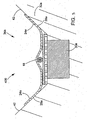
- Molded seat foam bun 700 depicted in Fig. 8 includes a trench portion 44, which includes a plateau 46 having lateral edges 48 and angled side walls 50.
- a touch fastener 52 is molded into plateau 46 and extends across lateral edges 48 and along a portion of angled sides 50, such that the distal edges 51 of the fastener are disposed out of the plane of the fastener element array, and directed town into the bun.
- Touch fastener 52 includes a base 10 portion having an upper face 12 and a lower face 14. Extending from the lower face 14 are male fastener elements 16 having stems integrally molded thereto.
- a magnetically attractable strip 18a is adhered to the upper face 12 of the base 10 and a film 40 covers magnetically attractable strip 18a and expands beyond the lateral edges of the base 10 to form selvedges 24a.
- the selvedges 24a are molded into the seat foam bun 700, creating a smooth surface on the lateral edges 48 and angled side 50 walls of the plateau 46.
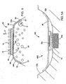
- the extension of selvedges 24a down side walls 50 can provide strong adherence between touch fastener 52 and seat foam bun 700 and improved resistance to delamination.
- upward force "F” is applied to touch fastener 52
- shear force "S” between angled selvedges 24a underlying foam and helping to prevent cracks from forming between touch fastener 52 and seat foam bun 700, which can lead to dislocation of touch fastener 700.
- While Seat cushion foam pads are flexible, it is desirable to mold rigid fasteners onto the surfaces of foam pads. When a rigid part is attached to the foam there can be areas of high stress concentration along the edges of the rigid part. In use, foam pads can tear along the rigid fasteners if the foam is worked around the rigid part.
- the flexible film edges described in Figs. 8 and 9 can move with the foam and can allow forces to be transferred gradually into the fastener component.
- the flexible can also edges resist crack propagation between the fastener and the foam and provide minimal stress risers.
- Tension forces that build up in the strip fastener as it holds the upholstery down can be spread out evenly over the inner portions of the fastener (rigid hook) and reduced rapidly at the edges. The result is that the forces of foam adhesion along the outer most edges of the film can be reduced. Where there is little force there will generally be little inclination to tear. Most of the forces are central in the fastener where edge cracking and failure propagation is not likely to occur.
- the selvedges 24a of the fastener product preferably are of a bending stiffness or flexural rigidity sufficiently low to enable the selvedges to be deflected into face-to-face contact with the side walls of the trench, and to allow the attractable magnetic forces to pull the central portion of the fastener product into planar contact with the bottom of the trench across the entire hook array.
- the selvedge bending stiffness should also be high enough to maintain a contact pressure between the selvedges and mold surface, preferably even along the lateral edges of the selvedges during the foaming process.
- a selvedge material having a flexural rigidity of between about 1000 and 3000 gm-cm, as measured in accordance with the Cantilever Test option of ASTM D1388, should be suitable.
- different applications may require varying the selvedge stiffness to optimize results.
- film has been described as suitable selvedge material, other materials can also be used to form selvedges, including paper or other fibrous material, rubber, cotton, or horse hair.
- fastener products discussed above may also be provided with protrusions or other fasteners on its back surface, which are shaped to become embedded in the foam of the seat bun to mechanically lock the fastener into the bun.
- thermally activatable resins examples include polyamides, polyurethanes, and other hot melt adhesives.
Landscapes
- Slide Fasteners, Snap Fasteners, And Hook Fasteners (AREA)
Claims (23)
- Combinaison d'une cavité de moule (27) et d'un produit de fixation à effleurement (52, 100, 200, 300, 400, 500, 500a, 600, 800, 900) pour l'utilisation comme insert de moule ;
la cavité de moule (27) définissant une tranchée (34a, 34b) ayant des parois latérales obliques (42) ;
le produit de fixation à effleurement étant situé à l'intérieur de la tranchée et comprenant :une base (10, 10a, 10b) comportant une face supérieure (12) et une face inférieure (14) et une partie centrale placée entre des bords latéraux (24, 24a, 24b), la partie centrale présentant une épaisseur nominale ;un matériau à attraction magnétique (18, 18a, 18b) fixé à la base (10, 10a, 10b) ; etune pluralité d'éléments de fixation (16, 16a) s'étendant dans une matrice (20) depuis la face inférieure (12) de la partie centrale de la base ;dans laquelle les bords (24, 24a, 24b) sont déviés pour se conformer aux parois latérales obliques (42) de la tranchée (34a, 34b) par attraction magnétique (30, 30a) du matériau à attraction magnétique (18, 18a, 18b). - Combinaison selon la revendication 1, dans laquelle le produit de fixation à effleurement (52, 100, 200, 300, 400, 500, 500a, 600, 800, 900) est constitué d'une unique résine contiguë.
- Combinaison selon la revendication 1 ou 2, dans laquelle la partie centrale comprend une bande d'un premier matériau supportant les éléments de fixation (16, 16a), et dans laquelle les bords (24, 24a, 24b) sont constitués d'un second matériau (40, 40a) de composition différente de celle du premier matériau.
- Combinaison selon la revendication 3, dans laquelle les bords (24, 24a, 24b) comprennent des régions d'un film (40, 40a), tel qu'un film polyamide, fixé à la face supérieure (12) de la base (10, 10a, 10b).
- Combinaison selon l'une quelconque des revendications 1 à 4, dans laquelle l'épaisseur nominale de la partie centrale de la base (10, 10a, 10b) est située entre environ 50 et 305 micros ou est supérieure à une épaisseur nominale des bords (24, 24a, 24b).
- Combinaison selon l'une quelconque des revendications précédentes, dans laquelle le matériau à attraction magnétique (18, 18a, 18b) comprend un fil métallique, ou une bande métallique, ou une couche de particules magnétiques, ou le matériau à attraction magnétique (18, 18a, 18b) est encapsulé dans une colle thermofusible.
- Combinaison selon l'une quelconque des revendications précédentes, dans laquelle chaque bord (24, 24a, 24b) s'étend depuis la matrice sur au moins environ 2 millimètres, par exemple au moins environ 4 millimètres ; ou les bords (24, 24a, 24b) sont constitués d'un matériau présentant une rigidité à la flexion d'environ 1000 à 3000 mg-cm, ou les bords (24, 24a, 24b) sont placés sur toutes les faces de la partie centrale de la base (10, 10a, 10b).
- Combinaison selon l'une quelconque des revendications précédentes, dans laquelle la partie centrale de la base (10, 10a, 10b) comprend une résine moulée.
- Combinaison selon l'une quelconque des revendications précédentes, dans laquelle les éléments de fixation (16, 16a) sont des éléments de fixation mâles (16, 16a) comprenant des tiges moulées en une seule pièce avec la partie centrale de la base (10, 10a, 10b).
- Procédé de façonnage d'une masse de mousse de siège (700) comprenant ;
la fourniture d'une cavité de moule (27) dont la forme correspond à celle de la masse de mousse de siège (700), dans lequel la cavité de moule (27) comprend une tranchée (34, 34a, 44) comportant des parois latérales plates (42) s'étendant à des angles aigus depuis une surface inférieure de la tranchée ou la tranchée (34, 34a, 44) présente des parois latérales incurvées (42), les bords (24, 24a, 24b) se conformant aux surfaces arquées des parois latérales (42) de tranchée, la fourniture d'un produit de fixation à effleurement (52, 100, 200, 300, 400, 500, 500a, 600, 800, 900) comprenant une base (10, 10a, 10b), un matériau à attraction magnétique (18, 18a, 18b) et une pluralité d'éléments de fixation (16, 16a) s'étendant depuis une face inférieure (14) d'une partie centrale de la base dans une matrice (20) située entre des bords latéraux (24, 24a, 24b) de la base (10, 10a, 10b) ;
le positionnement du produit de fixation à effleurement (52, 100, 200, 300, 400, 500, 500a, 600, 800, 900) le long de la tranchée (34, 34a, 44) avec les bords (24, 24a, 24b) déviés de leur position déchargée pour s'étendre le long des parois latérales (50) de tranchée (34, 34a, 44) dans un contact face-à-face ; et
la distribution d'une résine expansible (58) dans la cavité de moule (27) pour former une masse de mousse de siège (700), les bords déviés (24, 24a, 24b) résistant à l'intrusion de résine expansible (58) dans la matrice (20) des éléments de fixation (16, 16a, 16b). - Procédé selon la revendication 10, dans lequel une face inférieure (26) des bords (24, 24a, 24b) présente une surface essentiellement plate, ou dans lequel les bords (24, 24a, 24b) présentent une rigidité considérablement inférieure à celle de la partie centrale de la base (10, 10a, 10b).
- Procédé selon l'une quelconque des revendications 10 ou 11, dans lequel dans un état déchargé, les bords (24, 24a, 24b) et la partie centrale de la base (10, 10a, 10b) reposent dans un plan commun, les bords distaux des bords (24, 24a, 24b) étant déviés du plan commun avec le produit de fixation (52, 100, 200, 300, 400, 500, 500a, 600, 800, 900) étant positionné le long de la tranchée (34, 34a, 44).
- Procédé selon l'une quelconque des revendications 10 à 12, dans lequel les bords (24, 24a, 24b) comprennent un film (40, 40a).
- Procédé selon l'une quelconque des revendications précédentes 10 à 13, dans lequel la partie centrale de la base (10, 10a, 10b) présente une épaisseur nominale d'environ 50 à 305 microns, ou la partie centrale de la base (10, 10a, 10b) est plus épaisse que les bords (24, 24a, 24b).
- Procédé selon les revendications 10 à 14, dans lequel le matériau à attraction magnétique (18, 18a, 18b) est placé sur la face supérieure (12) de la partie centrale de la base (10, 10a, 10b) , ou dans lequel les bords (24, 24a, 24b) sont essentiellement dépourvus de matériau à attraction magnétique (18, 18a, 18b).
- Procédé selon l'une quelconque des revendications 10 à 15, dans lequel la tranchée (34, 34a) est allongée, et le produit de fixation (52, 100, 200, 300, 400, 500, 500a, 600, 800, 900) a la forme d'une bande.
- Procédé selon l'une quelconque des revendications 10 à 16, dans lequel les éléments de fixation (16, 16a) sont des éléments de fixation mâles comprenant des tiges moulées en une seule pièce avec une surface de la partie centrale de la base (10, 10a, 10b), ou dans lequel la résine expansible (56) comprend une résine polyuréthane.
- Masse de mousse de siège (700) comprenant ;
une masse de mousse ayant un plateau (46) placé sur une surface de celle-ci, et
positionné sur le plateau (46), un élément de fixation à effleurement (52, 100, 200, 300, 400, 500, 500a, 600, 800, 900) comprenant une base (10, 10a, 10b), un matériau à attraction magnétique (18, 18a, 18b) et une pluralité d'éléments de fixation (16, 16a) s'étendant depuis une partie centrale de la base (10, 10a, 10b) dans une matrice (20) placée entre des bords (24, 24a, 24b) de la base (10, 10a, 10b), dans laquelle les bords (24, 24a, 24b) sont encastrés dans la mousse (58) et s'étendent sur des bords latéraux supérieurs opposés du plateau (46). - Masse de mousse de siège selon la revendication 18, dans laquelle les bords (24, 24a, 24b) présentent une rigidité qui est sensiblement inférieure à celle de la partie centrale de la base (10, 10a, 10b).
- Masse de mousse de siège selon la revendication 19, dans laquelle les bords (24, 24a, 24b) comprennent un film (40, 40a).
- Masse de mousse de siège selon la revendication 19, dans laquelle le film (40, 40a) est collé à la partie centrale de la base (10, 10a, 10b).
- Masse de mousse de siège selon la revendication 19, dans laquelle la partie centrale de la base (10, 10a, 10b) est plus épaisse que les bords (24, 24a, 24b).
- Masse de mousse de siège selon l'une quelconque des revendications 19 à 22, dans laquelle une surface exposée des bords (24, 24a, 24b) est essentiellement lisse.
Applications Claiming Priority (2)
| Application Number | Priority Date | Filing Date | Title |
|---|---|---|---|
| US10/791,204 US7425360B2 (en) | 2004-03-02 | 2004-03-02 | Touch fastener products |
| PCT/IB2005/002140 WO2005096862A2 (fr) | 2004-03-02 | 2005-03-02 | Produits de fixation a effleurement |
Publications (2)
| Publication Number | Publication Date |
|---|---|
| EP1729609A2 EP1729609A2 (fr) | 2006-12-13 |
| EP1729609B1 true EP1729609B1 (fr) | 2011-11-02 |
Family
ID=34911617
Family Applications (1)
| Application Number | Title | Priority Date | Filing Date |
|---|---|---|---|
| EP05764674A Not-in-force EP1729609B1 (fr) | 2004-03-02 | 2005-03-02 | Produits de fixation a effleurement |
Country Status (5)
| Country | Link |
|---|---|
| US (2) | US7425360B2 (fr) |
| EP (1) | EP1729609B1 (fr) |
| CN (2) | CN1949995B (fr) |
| AT (1) | ATE531288T1 (fr) |
| WO (1) | WO2005096862A2 (fr) |
Families Citing this family (24)
| Publication number | Priority date | Publication date | Assignee | Title |
|---|---|---|---|---|
| US20070261224A1 (en) * | 2006-05-11 | 2007-11-15 | Dow Global Technologies Inc. | Methods and articles in having a fringed microprotrusion surface structure |
| WO2008102211A2 (fr) * | 2006-10-17 | 2008-08-28 | Velcro Industries B.V. | Fixations à effleurement |
| WO2008048992A2 (fr) * | 2006-10-17 | 2008-04-24 | Velcro Industries B.V. | Produits de fixation tactile |
| US20080088169A1 (en) * | 2006-10-17 | 2008-04-17 | Daniel Lee Janzen | Fastener Systems for Seat Cushions |
| JP3135909U (ja) * | 2007-07-20 | 2007-10-04 | クラレファスニング株式会社 | 座席表皮材の固定用テープ状係止部材 |
| US7954208B2 (en) * | 2007-10-31 | 2011-06-07 | Avery Dennison Corporation | Fastening member for a molded article |
| US20090276986A1 (en) * | 2008-05-12 | 2009-11-12 | Velcro Industries B.V. | Touch fastener products |
| US7854817B2 (en) * | 2008-05-29 | 2010-12-21 | 3M Innovative Properties Company | Methods and assemblies for attaching articles to surfaces |
| US8485380B1 (en) | 2008-08-05 | 2013-07-16 | Kenneth A. Abrams | Container reclosure device having a flexible band |
| TWI370726B (en) * | 2008-10-21 | 2012-08-21 | Taiwan Paiho Ltd | Fastening strap and manufacturing method thereof |
| TWI403282B (zh) * | 2008-12-05 | 2013-08-01 | Taiwan Paiho Ltd | 黏扣組件及具有黏扣組件之座墊 |
| TW201023783A (en) * | 2008-12-26 | 2010-07-01 | Taiwan Paiho Ltd | Fastening assembly and cushion having fastening assembly |
| US20120260401A1 (en) * | 2011-04-12 | 2012-10-18 | Darryl Moskowitz | Releasable securement device |
| DE102011104886A1 (de) * | 2011-06-18 | 2012-12-20 | Gottlieb Binder Gmbh & Co. Kg | Befestigungssystem |
| USD697726S1 (en) | 2012-09-20 | 2014-01-21 | Steelcase Inc. | Chair |
| TWI548360B (zh) * | 2012-10-15 | 2016-09-11 | 台灣百和工業股份有限公司 | 用於與發泡材料嵌合之黏扣組件及具有黏扣組件之座墊 |
| WO2014106896A1 (fr) * | 2013-01-07 | 2014-07-10 | Ykk株式会社 | Élément de fixation plat moulé et procédé de production pour un corps de coussin |
| US9655413B2 (en) | 2013-03-15 | 2017-05-23 | Thomas M. Adams | Self adhering connection surfaces, straps, snaps and bands |
| US9198483B2 (en) | 2013-03-15 | 2015-12-01 | Thomas M. Adams | Self adhering connection surfaces, straps, snaps and bands |
| DE102013009091A1 (de) * | 2013-05-28 | 2014-12-04 | Gottlieb Binder Gmbh & Co. Kg | Verfahren zum Herstellen eines Verbindungsteils, nach dem Verfahren hergestelltes Verbindungsteil, Werkzeug zum Herstellen eines solchen Verbindungsteils und Befestigungssystem mit einem derartigen Verbindungsteil |
| US9826801B2 (en) | 2015-06-17 | 2017-11-28 | Velcro BVBA | Mold-in touch fastening product |
| US9918526B2 (en) | 2015-06-17 | 2018-03-20 | Velcro BVBA | Mold-in touch fastening product |
| DE102017011245A1 (de) * | 2017-12-06 | 2019-06-06 | Gottlieb Binder Gmbh & Co. Kg | Haftverschlussteil |
| CN114599250A (zh) * | 2019-10-22 | 2022-06-07 | 可乐丽粘贴扣带株式会社 | 网状钩面紧固件及其制造方法以及带有面紧固件的成形体的制造方法 |
Citations (1)
| Publication number | Priority date | Publication date | Assignee | Title |
|---|---|---|---|---|
| DE3903847A1 (de) * | 1989-02-09 | 1990-08-16 | Metzeler Schaum Gmbh | Verfahren und vorrichtung zum einschaeumen und festlegen des haft- oder flauschbandes eines klettbandes in ein formschaumteil |
Family Cites Families (52)
| Publication number | Priority date | Publication date | Assignee | Title |
|---|---|---|---|---|
| US4470857A (en) | 1982-06-25 | 1984-09-11 | R. A. Casalou, Inc. | Method of making foam plastic article |
| FR2553156B1 (fr) | 1983-10-07 | 1985-12-27 | Aplix Sa | Bande ou analogue munie d'elements d'accrochage et destinee a etre portee par un article moule, et moule utilise |
| US4802939A (en) | 1983-12-13 | 1989-02-07 | Aplix, S.A. | Method for attaching a fastening tape to a molded article |
| CA1256278A (fr) | 1983-12-13 | 1989-06-27 | Bruno Queval | Bande d'accrochage destinee a etre fixee en cours de moulage sur un article a mouler et son procede de fixation |
| US4794028A (en) * | 1984-04-16 | 1988-12-27 | Velcro Industries B.V. | Method for continuously producing a multi-hook fastner member and product of the method |
| US4775310A (en) * | 1984-04-16 | 1988-10-04 | Velcro Industries B.V. | Apparatus for making a separable fastener |
| US4710414A (en) | 1984-07-10 | 1987-12-01 | Minnesota Mining And Manufacturing Company | Fastener assembly with heat shrinkable film cover |
| US4563380A (en) | 1984-07-10 | 1986-01-07 | Minnesota Mining And Manufacturing Company | Fastener assembly with improved temporary attachment layer |
| US4673542A (en) | 1985-06-14 | 1987-06-16 | General Motors Corporation | Method of making a foamed seat or cushion having integral fasteners |
| CA1285122C (fr) | 1985-07-17 | 1991-06-25 | Richard N. Hatch | Fixations separables pour le garnissage d'autres objets |
| US4814036A (en) | 1985-07-17 | 1989-03-21 | Velcro Industries B.V. | Method for adapting separable fasteners for attachment to other objects |
| US4881997A (en) | 1985-07-17 | 1989-11-21 | Velcro Industries. B.V. | Method for adapting separable fasteners for attachment to other objects |
| US4784890A (en) | 1986-06-20 | 1988-11-15 | Minnesota Mining And Manufacturing Company | Fastener assembly with peripheral temporary attachment layer |
| US4870725A (en) | 1987-01-12 | 1989-10-03 | Velcro Industries B.V. | Pop-through touch fastener |
| US4842916A (en) | 1987-01-19 | 1989-06-27 | Kuraray Company Ltd. | Separable fastener component & moldings attached with such fastener component |
| KR940006314B1 (ko) | 1987-12-15 | 1994-07-16 | 가부시끼가이샤 구라레 | 죔쇠 부재 |
| US5180618A (en) | 1990-01-25 | 1993-01-19 | Velcro Industries B.V. | Separable fasteners for attachment to other objects |
| US5061540A (en) | 1990-01-25 | 1991-10-29 | Velcro Industries B.V. | Separable fasteners for attachment to other objects |
| US5110649A (en) | 1990-07-03 | 1992-05-05 | Velcro Industries, B.V. | Separable fasteners for attachment to other objects |
| US5259905A (en) | 1990-08-09 | 1993-11-09 | Velcro Industries B.V. | Method for manufacturing a separable fastener for incorporation into a seat bun |
| US5540970A (en) | 1991-05-03 | 1996-07-30 | Velcro Industries B.V. | Die cut mold-in |
| CA2086326C (fr) | 1991-05-03 | 2001-12-25 | Donald L. Banfield | Dispositif de fixation incorpore par moulage |
| US5786061A (en) | 1991-05-03 | 1998-07-28 | Velcro Industries B.V. | Separable fastener having a perimeter cover gasket |
| US5260015A (en) * | 1991-08-16 | 1993-11-09 | Velcro Industries, B.V. | Method for making a laminated hook fastener |
| US5422156A (en) | 1993-04-23 | 1995-06-06 | Aplix, Inc. | Fastening member with ferromagnetic attachment strip |
| JP3404100B2 (ja) | 1993-11-29 | 2003-05-06 | 株式会社クラレ | モールドイン成形用係止部材 |
| US5500268A (en) | 1995-01-31 | 1996-03-19 | Aplix, Inc. | Fastener assembly with magnetic side and end seals and method |
| US5665449A (en) | 1995-01-31 | 1997-09-09 | Aplix, Inc. | Fastener assembly with mechanical end seals |
| US6540863B2 (en) | 1995-02-17 | 2003-04-01 | Velcro Industries B.V. | Forming fastener components of multiple streams of resin |
| US5606781A (en) | 1995-02-17 | 1997-03-04 | Velcro Industries, B.V. | Separable fastener having a bald perimeter rib bounded by fastening elements |
| US5725928A (en) | 1995-02-17 | 1998-03-10 | Velcro Industries B.V. | Touch fastener with magnetic attractant |
| US5766385A (en) | 1995-12-06 | 1998-06-16 | Velcro Industries B.V. | Separable fastener having die-cut protective cover with pull tab and method of making same |
| US5945193A (en) | 1995-12-06 | 1999-08-31 | Velcro Industries B.V. | Touch fastener with porous metal containing layer |
| GB9525638D0 (en) * | 1995-12-15 | 1996-02-14 | Philips Electronics Nv | Matrix display devices |
| US5766723A (en) | 1996-11-12 | 1998-06-16 | Woodbridge Foam Corporation | Fastener assembly with peripheral seal |
| US5900303A (en) | 1997-09-30 | 1999-05-04 | Aplix, Inc. | Fastener assembly with mechanical end seals |
| DE19752763A1 (de) | 1997-11-28 | 1999-07-01 | Binder Gottlieb Gmbh & Co | Haftkörper |
| FR2786070B1 (fr) | 1998-11-19 | 2000-12-22 | Aplix Sa | Bande stratifiee auto-agrippante |
| DE19956011A1 (de) | 1999-11-20 | 2001-06-21 | Binder Gottlieb Gmbh & Co | Haftverschlußteil |
| US6460230B2 (en) | 2000-01-12 | 2002-10-08 | Kuraray Co., Ltd. | Mold-in fastening member and production of molded resin article having mold-in fastening member |
| US6596371B1 (en) | 2000-01-19 | 2003-07-22 | Aplix, Inc. | Component for overcasting for a moulded object |
| US6656563B1 (en) | 2000-05-23 | 2003-12-02 | Velcro Industries B.V. | Segmented separable fastener |
| JP3699896B2 (ja) | 2000-06-30 | 2005-09-28 | Ykk株式会社 | シート用面ファスナー |
| CA2353513A1 (fr) | 2000-07-14 | 2002-01-14 | James Curtin | Element de coussin moule et methode de production |
| DE10039940A1 (de) | 2000-08-16 | 2002-03-07 | Binder Gottlieb Gmbh & Co | Haftverschlußteil |
| US6468624B1 (en) | 2000-11-20 | 2002-10-22 | Ykk Corporation Of America | Fastener strip with magnetic attractant |
| US7022394B2 (en) | 2001-05-04 | 2006-04-04 | Ykk Corporation | Fastener strip with discrete magnetically attractable area, and method and apparatus of making same |
| US6720059B2 (en) | 2001-05-04 | 2004-04-13 | Ykk Corporation | Fastener strip having vertical sealing members l |
| US6650033B2 (en) * | 2001-08-06 | 2003-11-18 | Tyco Electronics Corporation | Foamable coupling for lamp assembly and methods for using the coupling |
| US6913810B2 (en) | 2002-01-15 | 2005-07-05 | Velcro Industries B.V. | Interface tape |
| US6668429B2 (en) | 2002-05-03 | 2003-12-30 | Ykk Corporation Of America | Deep-groove fastener |
| FR2846274B1 (fr) | 2002-10-23 | 2004-12-17 | Aplix Sa | Surmoule a petite bande a crochets |
-
2004
- 2004-03-02 US US10/791,204 patent/US7425360B2/en not_active Expired - Lifetime
-
2005
- 2005-03-02 EP EP05764674A patent/EP1729609B1/fr not_active Not-in-force
- 2005-03-02 CN CN2005800135559A patent/CN1949995B/zh not_active Expired - Fee Related
- 2005-03-02 WO PCT/IB2005/002140 patent/WO2005096862A2/fr active Application Filing
- 2005-03-02 AT AT05764674T patent/ATE531288T1/de active
- 2005-03-02 CN CN201110211479XA patent/CN102228329B/zh not_active Expired - Fee Related
-
2008
- 2008-05-21 US US12/124,361 patent/US7678318B2/en not_active Expired - Lifetime
Patent Citations (1)
| Publication number | Priority date | Publication date | Assignee | Title |
|---|---|---|---|---|
| DE3903847A1 (de) * | 1989-02-09 | 1990-08-16 | Metzeler Schaum Gmbh | Verfahren und vorrichtung zum einschaeumen und festlegen des haft- oder flauschbandes eines klettbandes in ein formschaumteil |
Also Published As
| Publication number | Publication date |
|---|---|
| WO2005096862A2 (fr) | 2005-10-20 |
| US20080284060A1 (en) | 2008-11-20 |
| CN102228329B (zh) | 2013-09-04 |
| ATE531288T1 (de) | 2011-11-15 |
| WO2005096862A3 (fr) | 2006-03-09 |
| US20050196599A1 (en) | 2005-09-08 |
| US7425360B2 (en) | 2008-09-16 |
| CN102228329A (zh) | 2011-11-02 |
| US7678318B2 (en) | 2010-03-16 |
| CN1949995B (zh) | 2011-09-14 |
| EP1729609A2 (fr) | 2006-12-13 |
| CN1949995A (zh) | 2007-04-18 |
Similar Documents
| Publication | Publication Date | Title |
|---|---|---|
| EP1729609B1 (fr) | Produits de fixation a effleurement | |
| US7648751B2 (en) | Touch fastener products | |
| US20090276986A1 (en) | Touch fastener products | |
| US5671511A (en) | Interengaging fastener member having fabric layer | |
| JP6066332B2 (ja) | 次元的に柔軟なタッチ・ファスナー・ストリップ | |
| EP0921739B1 (fr) | Fixation separable a joint peripherique de fermeture | |
| EP1913832B1 (fr) | Fixations tactiles moulées et procédé de fabrication | |
| US5180618A (en) | Separable fasteners for attachment to other objects | |
| CA2779810C (fr) | Fixation liberable le long d'un bourrelet | |
| WO2009131044A1 (fr) | Elément d'accrochage pour un moulage dans un moule | |
| JPWO2009013998A1 (ja) | 座席表皮材の固定用テープ状係止部材、及び係止部材付き樹脂成形体の製造方法 | |
| EP4143446B1 (fr) | Éléments de fixation moulés | |
| EP1348530B1 (fr) | Elément de fermeture et procédé de production d'un article en résine moulé pourvu d'un tel élément | |
| JPH0711621Y2 (ja) | 留め部材 | |
| JP3255384B2 (ja) | モールドイン成形体、成形方法、成形用係止部材 | |
| EP3143897B1 (fr) | Élément de fixation de surface, structure de coussin, et structure de siège | |
| EP2073659B1 (fr) | Systèmes de fixation pour coussins de siège | |
| KR20030007290A (ko) | 쿠션에 일체로 부착되는 벨크로파스너 | |
| JPH0738806B2 (ja) | フアスナ材 |
Legal Events
| Date | Code | Title | Description |
|---|---|---|---|
| PUAI | Public reference made under article 153(3) epc to a published international application that has entered the european phase |
Free format text: ORIGINAL CODE: 0009012 |
|
| 17P | Request for examination filed |
Effective date: 20060921 |
|
| AK | Designated contracting states |
Kind code of ref document: A2 Designated state(s): AT BE BG CH CY CZ DE DK EE ES FI FR GB GR HU IE IS IT LI LT LU MC NL PL PT RO SE SI SK TR |
|
| 17Q | First examination report despatched |
Effective date: 20070221 |
|
| DAX | Request for extension of the european patent (deleted) | ||
| GRAP | Despatch of communication of intention to grant a patent |
Free format text: ORIGINAL CODE: EPIDOSNIGR1 |
|
| GRAJ | Information related to disapproval of communication of intention to grant by the applicant or resumption of examination proceedings by the epo deleted |
Free format text: ORIGINAL CODE: EPIDOSDIGR1 |
|
| GRAP | Despatch of communication of intention to grant a patent |
Free format text: ORIGINAL CODE: EPIDOSNIGR1 |
|
| GRAC | Information related to communication of intention to grant a patent modified |
Free format text: ORIGINAL CODE: EPIDOSCIGR1 |
|
| GRAS | Grant fee paid |
Free format text: ORIGINAL CODE: EPIDOSNIGR3 |
|
| GRAA | (expected) grant |
Free format text: ORIGINAL CODE: 0009210 |
|
| AK | Designated contracting states |
Kind code of ref document: B1 Designated state(s): AT BE BG CH CY CZ DE DK EE ES FI FR GB GR HU IE IS IT LI LT LU MC NL PL PT RO SE SI SK TR |
|
| REG | Reference to a national code |
Ref country code: GB Ref legal event code: FG4D |
|
| REG | Reference to a national code |
Ref country code: CH Ref legal event code: EP |
|
| REG | Reference to a national code |
Ref country code: DE Ref legal event code: R081 Ref document number: 602005030986 Country of ref document: DE Owner name: VELCRO BVBA, BE Free format text: FORMER OWNER: VELCRO INDUSTRIES B.V., CURACAO, AN |
|
| REG | Reference to a national code |
Ref country code: IE Ref legal event code: FG4D |
|
| REG | Reference to a national code |
Ref country code: DE Ref legal event code: R096 Ref document number: 602005030986 Country of ref document: DE Effective date: 20120112 |
|
| REG | Reference to a national code |
Ref country code: NL Ref legal event code: VDEP Effective date: 20111102 |
|
| LTIE | Lt: invalidation of european patent or patent extension |
Effective date: 20111102 |
|
| PG25 | Lapsed in a contracting state [announced via postgrant information from national office to epo] |
Ref country code: LT Free format text: LAPSE BECAUSE OF FAILURE TO SUBMIT A TRANSLATION OF THE DESCRIPTION OR TO PAY THE FEE WITHIN THE PRESCRIBED TIME-LIMIT Effective date: 20111102 Ref country code: IS Free format text: LAPSE BECAUSE OF FAILURE TO SUBMIT A TRANSLATION OF THE DESCRIPTION OR TO PAY THE FEE WITHIN THE PRESCRIBED TIME-LIMIT Effective date: 20120302 |
|
| PG25 | Lapsed in a contracting state [announced via postgrant information from national office to epo] |
Ref country code: PT Free format text: LAPSE BECAUSE OF FAILURE TO SUBMIT A TRANSLATION OF THE DESCRIPTION OR TO PAY THE FEE WITHIN THE PRESCRIBED TIME-LIMIT Effective date: 20120302 Ref country code: NL Free format text: LAPSE BECAUSE OF FAILURE TO SUBMIT A TRANSLATION OF THE DESCRIPTION OR TO PAY THE FEE WITHIN THE PRESCRIBED TIME-LIMIT Effective date: 20111102 Ref country code: PL Free format text: LAPSE BECAUSE OF FAILURE TO SUBMIT A TRANSLATION OF THE DESCRIPTION OR TO PAY THE FEE WITHIN THE PRESCRIBED TIME-LIMIT Effective date: 20111102 Ref country code: GR Free format text: LAPSE BECAUSE OF FAILURE TO SUBMIT A TRANSLATION OF THE DESCRIPTION OR TO PAY THE FEE WITHIN THE PRESCRIBED TIME-LIMIT Effective date: 20120203 Ref country code: SE Free format text: LAPSE BECAUSE OF FAILURE TO SUBMIT A TRANSLATION OF THE DESCRIPTION OR TO PAY THE FEE WITHIN THE PRESCRIBED TIME-LIMIT Effective date: 20111102 Ref country code: BE Free format text: LAPSE BECAUSE OF FAILURE TO SUBMIT A TRANSLATION OF THE DESCRIPTION OR TO PAY THE FEE WITHIN THE PRESCRIBED TIME-LIMIT Effective date: 20111102 Ref country code: SI Free format text: LAPSE BECAUSE OF FAILURE TO SUBMIT A TRANSLATION OF THE DESCRIPTION OR TO PAY THE FEE WITHIN THE PRESCRIBED TIME-LIMIT Effective date: 20111102 |
|
| PG25 | Lapsed in a contracting state [announced via postgrant information from national office to epo] |
Ref country code: CY Free format text: LAPSE BECAUSE OF FAILURE TO SUBMIT A TRANSLATION OF THE DESCRIPTION OR TO PAY THE FEE WITHIN THE PRESCRIBED TIME-LIMIT Effective date: 20111102 |
|
| PG25 | Lapsed in a contracting state [announced via postgrant information from national office to epo] |
Ref country code: DK Free format text: LAPSE BECAUSE OF FAILURE TO SUBMIT A TRANSLATION OF THE DESCRIPTION OR TO PAY THE FEE WITHIN THE PRESCRIBED TIME-LIMIT Effective date: 20111102 Ref country code: BG Free format text: LAPSE BECAUSE OF FAILURE TO SUBMIT A TRANSLATION OF THE DESCRIPTION OR TO PAY THE FEE WITHIN THE PRESCRIBED TIME-LIMIT Effective date: 20120202 Ref country code: EE Free format text: LAPSE BECAUSE OF FAILURE TO SUBMIT A TRANSLATION OF THE DESCRIPTION OR TO PAY THE FEE WITHIN THE PRESCRIBED TIME-LIMIT Effective date: 20111102 Ref country code: CZ Free format text: LAPSE BECAUSE OF FAILURE TO SUBMIT A TRANSLATION OF THE DESCRIPTION OR TO PAY THE FEE WITHIN THE PRESCRIBED TIME-LIMIT Effective date: 20111102 Ref country code: SK Free format text: LAPSE BECAUSE OF FAILURE TO SUBMIT A TRANSLATION OF THE DESCRIPTION OR TO PAY THE FEE WITHIN THE PRESCRIBED TIME-LIMIT Effective date: 20111102 |
|
| PG25 | Lapsed in a contracting state [announced via postgrant information from national office to epo] |
Ref country code: IT Free format text: LAPSE BECAUSE OF FAILURE TO SUBMIT A TRANSLATION OF THE DESCRIPTION OR TO PAY THE FEE WITHIN THE PRESCRIBED TIME-LIMIT Effective date: 20111102 Ref country code: RO Free format text: LAPSE BECAUSE OF FAILURE TO SUBMIT A TRANSLATION OF THE DESCRIPTION OR TO PAY THE FEE WITHIN THE PRESCRIBED TIME-LIMIT Effective date: 20111102 |
|
| PLBE | No opposition filed within time limit |
Free format text: ORIGINAL CODE: 0009261 |
|
| STAA | Information on the status of an ep patent application or granted ep patent |
Free format text: STATUS: NO OPPOSITION FILED WITHIN TIME LIMIT |
|
| REG | Reference to a national code |
Ref country code: AT Ref legal event code: MK05 Ref document number: 531288 Country of ref document: AT Kind code of ref document: T Effective date: 20111102 |
|
| 26N | No opposition filed |
Effective date: 20120803 |
|
| PG25 | Lapsed in a contracting state [announced via postgrant information from national office to epo] |
Ref country code: MC Free format text: LAPSE BECAUSE OF NON-PAYMENT OF DUE FEES Effective date: 20120331 |
|
| REG | Reference to a national code |
Ref country code: CH Ref legal event code: PL |
|
| GBPC | Gb: european patent ceased through non-payment of renewal fee |
Effective date: 20120302 |
|
| REG | Reference to a national code |
Ref country code: DE Ref legal event code: R097 Ref document number: 602005030986 Country of ref document: DE Effective date: 20120803 |
|
| REG | Reference to a national code |
Ref country code: FR Ref legal event code: ST Effective date: 20121130 |
|
| REG | Reference to a national code |
Ref country code: IE Ref legal event code: MM4A |
|
| PG25 | Lapsed in a contracting state [announced via postgrant information from national office to epo] |
Ref country code: AT Free format text: LAPSE BECAUSE OF FAILURE TO SUBMIT A TRANSLATION OF THE DESCRIPTION OR TO PAY THE FEE WITHIN THE PRESCRIBED TIME-LIMIT Effective date: 20111102 Ref country code: IE Free format text: LAPSE BECAUSE OF NON-PAYMENT OF DUE FEES Effective date: 20120302 Ref country code: FR Free format text: LAPSE BECAUSE OF NON-PAYMENT OF DUE FEES Effective date: 20120402 Ref country code: GB Free format text: LAPSE BECAUSE OF NON-PAYMENT OF DUE FEES Effective date: 20120302 Ref country code: CH Free format text: LAPSE BECAUSE OF NON-PAYMENT OF DUE FEES Effective date: 20120331 Ref country code: LI Free format text: LAPSE BECAUSE OF NON-PAYMENT OF DUE FEES Effective date: 20120331 |
|
| PG25 | Lapsed in a contracting state [announced via postgrant information from national office to epo] |
Ref country code: ES Free format text: LAPSE BECAUSE OF FAILURE TO SUBMIT A TRANSLATION OF THE DESCRIPTION OR TO PAY THE FEE WITHIN THE PRESCRIBED TIME-LIMIT Effective date: 20120213 |
|
| PG25 | Lapsed in a contracting state [announced via postgrant information from national office to epo] |
Ref country code: FI Free format text: LAPSE BECAUSE OF FAILURE TO SUBMIT A TRANSLATION OF THE DESCRIPTION OR TO PAY THE FEE WITHIN THE PRESCRIBED TIME-LIMIT Effective date: 20111102 |
|
| PG25 | Lapsed in a contracting state [announced via postgrant information from national office to epo] |
Ref country code: TR Free format text: LAPSE BECAUSE OF FAILURE TO SUBMIT A TRANSLATION OF THE DESCRIPTION OR TO PAY THE FEE WITHIN THE PRESCRIBED TIME-LIMIT Effective date: 20111102 |
|
| PG25 | Lapsed in a contracting state [announced via postgrant information from national office to epo] |
Ref country code: LU Free format text: LAPSE BECAUSE OF NON-PAYMENT OF DUE FEES Effective date: 20120302 |
|
| PG25 | Lapsed in a contracting state [announced via postgrant information from national office to epo] |
Ref country code: HU Free format text: LAPSE BECAUSE OF FAILURE TO SUBMIT A TRANSLATION OF THE DESCRIPTION OR TO PAY THE FEE WITHIN THE PRESCRIBED TIME-LIMIT Effective date: 20050302 |
|
| REG | Reference to a national code |
Ref country code: DE Ref legal event code: R082 Ref document number: 602005030986 Country of ref document: DE Representative=s name: MUELLER-BORE & PARTNER PATENTANWAELTE PARTG MB, DE Ref country code: DE Ref legal event code: R081 Ref document number: 602005030986 Country of ref document: DE Owner name: VELCRO BVBA, BE Free format text: FORMER OWNER: VELCRO INDUSTRIES B.V., CURACAO, AN |
|
| PGFP | Annual fee paid to national office [announced via postgrant information from national office to epo] |
Ref country code: DE Payment date: 20170329 Year of fee payment: 13 |
|
| REG | Reference to a national code |
Ref country code: DE Ref legal event code: R119 Ref document number: 602005030986 Country of ref document: DE |
|
| PG25 | Lapsed in a contracting state [announced via postgrant information from national office to epo] |
Ref country code: DE Free format text: LAPSE BECAUSE OF NON-PAYMENT OF DUE FEES Effective date: 20181002 |