EP1729098B1 - A servo cleat for an encoder and an encoder including a servo cleat - Google Patents
A servo cleat for an encoder and an encoder including a servo cleat Download PDFInfo
- Publication number
- EP1729098B1 EP1729098B1 EP06007239A EP06007239A EP1729098B1 EP 1729098 B1 EP1729098 B1 EP 1729098B1 EP 06007239 A EP06007239 A EP 06007239A EP 06007239 A EP06007239 A EP 06007239A EP 1729098 B1 EP1729098 B1 EP 1729098B1
- Authority
- EP
- European Patent Office
- Prior art keywords
- cleat
- encoder
- motor
- mounting
- servo
- Prior art date
- Legal status (The legal status is an assumption and is not a legal conclusion. Google has not performed a legal analysis and makes no representation as to the accuracy of the status listed.)
- Not-in-force
Links
- 210000005069 ears Anatomy 0.000 claims abstract description 38
- 239000004033 plastic Substances 0.000 claims description 6
- 239000002991 molded plastic Substances 0.000 claims description 5
- 238000005452 bending Methods 0.000 description 1
- 230000008878 coupling Effects 0.000 description 1
- 238000010168 coupling process Methods 0.000 description 1
- 238000005859 coupling reaction Methods 0.000 description 1
- -1 e.g. Substances 0.000 description 1
- 238000009434 installation Methods 0.000 description 1
- 238000004519 manufacturing process Methods 0.000 description 1
- 239000002184 metal Substances 0.000 description 1
- 230000003287 optical effect Effects 0.000 description 1
- 238000000926 separation method Methods 0.000 description 1
- 238000004804 winding Methods 0.000 description 1
Images


Classifications
-
- G—PHYSICS
- G01—MEASURING; TESTING
- G01D—MEASURING NOT SPECIALLY ADAPTED FOR A SPECIFIC VARIABLE; ARRANGEMENTS FOR MEASURING TWO OR MORE VARIABLES NOT COVERED IN A SINGLE OTHER SUBCLASS; TARIFF METERING APPARATUS; MEASURING OR TESTING NOT OTHERWISE PROVIDED FOR
- G01D11/00—Component parts of measuring arrangements not specially adapted for a specific variable
- G01D11/30—Supports specially adapted for an instrument; Supports specially adapted for a set of instruments
-
- G—PHYSICS
- G01—MEASURING; TESTING
- G01D—MEASURING NOT SPECIALLY ADAPTED FOR A SPECIFIC VARIABLE; ARRANGEMENTS FOR MEASURING TWO OR MORE VARIABLES NOT COVERED IN A SINGLE OTHER SUBCLASS; TARIFF METERING APPARATUS; MEASURING OR TESTING NOT OTHERWISE PROVIDED FOR
- G01D5/00—Mechanical means for transferring the output of a sensing member; Means for converting the output of a sensing member to another variable where the form or nature of the sensing member does not constrain the means for converting; Transducers not specially adapted for a specific variable
- G01D5/26—Mechanical means for transferring the output of a sensing member; Means for converting the output of a sensing member to another variable where the form or nature of the sensing member does not constrain the means for converting; Transducers not specially adapted for a specific variable characterised by optical transfer means, i.e. using infrared, visible, or ultraviolet light
- G01D5/32—Mechanical means for transferring the output of a sensing member; Means for converting the output of a sensing member to another variable where the form or nature of the sensing member does not constrain the means for converting; Transducers not specially adapted for a specific variable characterised by optical transfer means, i.e. using infrared, visible, or ultraviolet light with attenuation or whole or partial obturation of beams of light
- G01D5/34—Mechanical means for transferring the output of a sensing member; Means for converting the output of a sensing member to another variable where the form or nature of the sensing member does not constrain the means for converting; Transducers not specially adapted for a specific variable characterised by optical transfer means, i.e. using infrared, visible, or ultraviolet light with attenuation or whole or partial obturation of beams of light the beams of light being detected by photocells
- G01D5/347—Mechanical means for transferring the output of a sensing member; Means for converting the output of a sensing member to another variable where the form or nature of the sensing member does not constrain the means for converting; Transducers not specially adapted for a specific variable characterised by optical transfer means, i.e. using infrared, visible, or ultraviolet light with attenuation or whole or partial obturation of beams of light the beams of light being detected by photocells using displacement encoding scales
- G01D5/3473—Circular or rotary encoders
- G01D5/34738—Axles; Driving or coupling means
-
- Y—GENERAL TAGGING OF NEW TECHNOLOGICAL DEVELOPMENTS; GENERAL TAGGING OF CROSS-SECTIONAL TECHNOLOGIES SPANNING OVER SEVERAL SECTIONS OF THE IPC; TECHNICAL SUBJECTS COVERED BY FORMER USPC CROSS-REFERENCE ART COLLECTIONS [XRACs] AND DIGESTS
- Y10—TECHNICAL SUBJECTS COVERED BY FORMER USPC
- Y10T—TECHNICAL SUBJECTS COVERED BY FORMER US CLASSIFICATION
- Y10T403/00—Joints and connections
- Y10T403/70—Interfitted members
Definitions
- the present invention relates to a servo cleat for an encoder, an encoder including a servo cleat and a system including an encoder, a motor and a servo cleat.
- Encoders are used to measure angular or linear motion. A common use of encoders is for computer numeric control (CNC) machines. Encoder housings may be made of metal, e.g., in a bearing encoder, or plastic, e.g., in a modular encoder, and may include printed circuit boards (PCB).
- PCB printed circuit boards
- the surface of the housing that contacts the motor is made of non-conductive plastic.
- an O-bracket and a wire may be soldered to the PCB to create an electrical connection between the PCB and the motor.
- U.S. Patent No. 4,338,517 to Perrine is believed to relate to a shaft rotation sensor.
- a modular incremental rotary shaft encoder is preassembled within its housing and then installed and aligned upon the shaft of which rotation is to be sensed.
- the encoder housing loosely confines a thin disc assembly having a shaft receiving aperture dimensioned to be a press fit upon the shaft.
- the encoder is installed simply by pressing the housing and the disc assembly therein upon the shaft and fixing the housing to the shaft support.
- the disc assembly plane of rotation and the disc to detector gap are fixed by inserting a slender elongated installation tool through the housing cover into engagement with the disc assembly and pressing and bending the disc assembly against a fixed stop while the shaft and disc assembly are rotated.
- a pointed tool is inserted through the housing against the disc assembly to hold the latter against rotation while the shaft is carefully rotated to provide for rotational indexing of the disc assembly.
- U.S. Patent No. 5,859,425 to Mleinek et al. is believed to relate to an encoder having first and second housing portions and guide means.
- the encoder includes a casing having an open end and a base which fits in the open end. Trapezoidal cut-outs in the casing are arranged to receive partly trapezoidal projections on the base.
- the casing contains an optical sensor, a circuit board for operation of the sensor, and a timing disc mounted on a rotary hub.
- the hub has a passage for a drive shaft of a motor, and the passage is in register with an opening in the base. During assembly, the drive shaft is passed through the opening in the base and the motor and casing are urged towards one another to push the base into the casing.
- the projections When the base enters the casing, the projections are received in the cut-outs and a guide surface in the casing engages a centring surface on the hub. Once the projections are in the cut-outs, the casing and the base are rotated relative to each other to secure the base to the casing. Due to the trapezoidal shape of the cut-outs and the partly trapezoidal shape of the projections, the casing moves in a direction away from the base during rotation. This causes the guide surface of the casing to disengage from the centring surface of the hub.
- DE 197 39 012 A1 relates to a device for mounting an angle sensor on an object, e.g. a machine tool.
- This mounting device comprises one resilient member, one slidable member and one locking member.
- the slidable member is biased by the resilient member in a mounting position and co-operates through this bias with the locking member so that this locking member engages with a recess in the angle sensor.
- a device for mounting an encoder on a motor includes: a first part including at least one first mounting ear; and a second part including at least one second mounting ear, a first end of the first part adapted to connect to a second end of the second part, a second end of the first part adapted to connect to a first end of the second part to form a substantially circular cleat, an inner diameter of the cleat adapted to couple to a housing of the encoder, the mounting ears adapted to mount to the motor.
- the inner diameter of the cleat includes at least one inner boss adapted to be received in a groove of the housing of the encoder.
- the first part and the second part may be substantially identical.
- a connector of the first end of the first part may be connectable to a connector of the second end of the second part, and a connector of the second end of the first part may be connectable to a connector of the first end of the second part.
- the connectors may be self-complementary.
- the first part and the second part may be self-complementary.
- Each of the first part and the second part may be substantially semi-circular.
- the inner boss may be axially asymmetric.
- the cleat may be coupleable to the housing in at least two orientations.
- a first orientation may be such that a first surface of the cleat corresponds to a bottom surface of the cleat and is substantially coplanar with a bottom surface of the motor, and a second surface of the cleat opposite the first surface is spaced apart from the bottom surface of the motor.
- a second, inverted orientation may be such that the second surface of the cleat corresponds to the bottom surface of the cleat and is spaced apart from the bottom surface of the motor, and the first surface of the cleat is spaced apart from the bottom surface of the motor.
- the cleat and encoder may be flush-mountable to the motor in the first orientation and mountable in a recessed pilot in the motor in the second orientation.
- At least one surface of the mounting ears may be arranged at an angle with respect to a mounting surface of the cleat to urge the encoder against the motor.
- the mounting ears may be one of: (a) arranged symmetrically around a circumference of the cleat; and (b) arranged asymmetrically around the circumference of the cleat.
- An angular extent of the inner boss may be less than an angular extent of the groove.
- a difference between the angular extent of the groove and the angular extent of the inner boss may define an angular adjustment range between the cleat and the housing of the encoder.
- a difference between the angular extent of the groove and the angular extent of the inner boss may define an angular adjustment range between the encoder and the motor.
- the mounting ears may be selectively removable from the first and second parts.
- Each mounting ear may include a bore configured to receive a fastener there through to mount the cleat to the motor.
- the first part and the second part may be formed of plastic, e.g., moulded plastic.
- a device for mounting an encoder on a motor includes a plurality of arcuate parts. A first end of each part is adapted to connect to a second end of an adjacent part to form a substantially circular cleat. An inner diameter of the cleat is adapted to couple to a housing of the encoder, and the cleat includes at least one mounting ear adapted to mount to the motor.
- the plurality of parts may include: (a) two semicircular parts; (b) three third-circular parts; or (c) four quarter-circular parts.
- an encoder in an example embodiment of the present invention, includes: housing; and a device adapted to mount the housing on a motor.
- the device includes a first part including at least one first mounting ear and a second part including at least one second mounting ear. A first end of the first part is adapted to connect to a second end of the second part, a second end of the first part is adapted to connect to a first end of the second part to form a substantially circular cleat.
- An inner diameter of the cleat is adapted to couple to the housing, and the mounting ears are adapted to mount to the motor.
- a system for measuring angular movement may include a motor, an encoder, and a device adapted to mount the encoder on the motor.
- the device includes a first part including at least one first mounting ear and a second part including at least one second mounting ear. A first end of the first part is adapted to connect to a second end of the second part, and a second end of the first part is adapted to connect to a first end of the second part to form a substantially circular cleat.
- An inner diameter of the cleat is adapted to couple to a housing of the encoder, and the mounting ears adapted to mount to the motor.
- a servo cleat which is formed of plastic parts, e.g., moulded plastic parts, is arranged to mount an encoder on a motor utilising its servo ring.
- a device includes two parts, which may be formed of moulded plastic and which may be semi-circular.
- the parts are formed such that two semi-circular parts interlock together to create a full circular cleat, as illustrated, for example in Figure 2 .
- the two parts may be identical, e.g., self-complementary, and, when mated together, may form a complete circle.
- An exemplary embodiment of the present invention may reduce tooling costs, may reduce part costs and may simplify inventory management by providing one part that interlocks with itself to form a substantially circular cleat.
- the moulded plastic semi-circular part may include an inner boss that engages a groove on the encoder. Because the boss is created axially asymmetrically on an inner diameter of the moulded cleat, the boss may provide two alternative mounting orientations.
- the servo cleat may be used to mount an encoder on a flat surface, e.g., flush or pilotless mounting. Alternatively, the servo cleat may be used to mount the encoder in a recessed pilot.
- the encoder may be rotated to facilitate alignment of commutation tracks with the motor windings by not tightening completely the mounting screws of the servo cleat. Additionally, the angle of the mounting surface on the moulded servo cleat may provide that, when screwed down, the inclined surface of the servo-cleat creates a downward force on the boss. The boss may thereby engage the servo-ring of the encoder and allow no further movement.
- the moulded servo cleat may also have options in the mould tooling to provide for alternative mounting patterns. For example, with three extra mounting ears, a customer may select from a variety of mounting options. These may be available on all parts or may be available at the option of the user by providing distinct configurations of the moulded part. Furthermore, depending on the combination of moulded parts, numerous mounting configurations may be provided or selectable.
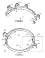
- Figure 1 is a perspective view of a part 10, which is a moulded, plastic component.
- Moulded part 10 is semi-circular, but may also be a smaller fraction of a circle, for example, one-third or one-quarter of a circle.
- Moulded part 10 includes connectors, e.g., snap locks 11.1 and 11.2, arranged at the terminal ends of moulded part 10. Snap locks 11.1 and 11.2 are cooperating elements adapted to interlock with corresponding snap locks.
- the snap locks 11.1, 11.2 are arranged so that the moulded part 10 is self-complementary, e.g., one moulded part 10 is connectable to another moulded part 10 by connection of the snap lock 11.1 of one moulded part 10 to the snap lock 11.2 of the other moulded part 10, and vice versa.
- Snap lock 11.1 is a receiving attachment arrangement
- snap lock 11.2 is a protruding attachment arrangement.
- Mounting ears 12.1, 12.2, 12.3, and 12.4 are arranged on an outside edge of moulded part 10 separated radially by various angles. For example, mounting ears 12.1 and 12.2 are separated by 60 degrees, mounting ears 12.2 and 12.3 are separated by 30 degrees, and mounting ears 12.3 and 12.4 are separated by 30 degrees.
- mounting ears may provide that the assembled cleat 20 includes mounting ears arranged symmetrically around the circumference of the cleat or asymmetrically around the circumference of the cleat.
- Moulded part 10 of Figure 1 also includes major inner boss 13 and minor inner boss 14.
- Major inner boss 13 and minor inner boss 14 extend inwardly from an inner diameter of moulded part 10 on a bottom edge of the inner diameter of moulded part 10.
- the major inner boss 13 of one part 10 abuts and is continuous with the minor inner boss 14 of the other part 10 and vice versa.
- This arrangement of the bosses 13, 14 is illustrated, for example, in Figures 2 and 4 to 7 .
- Figure 2 is a perspective view of two moulded parts 10.1 and 10.2 that are connected together by their connectors to form servo cleat 20. If moulded parts 10 are a lesser fraction of a circle, a corresponding larger number of moulded parts 10 are required to form the circular servo cleat 10.
- Moulded part 10.1 includes snap locks 11.1 and 11.2, and moulded part 10.2 includes snap locks 11.3 and 11.4. Snap lock 11.1 engages snap lock 11.3, and snap lock 11.2 engages snap lock 11.4 to form servo cleat 20. Snap locks 11.1, 11.4 are identical and snap locks 11.2, 11.3 are identical so that the moulded parts 10.1, 10.2 are self-complementary.
- the connectors themselves may also be self-complementary.
- Mounting ear 12.4 is arranged on an outside edge of moulded part 10.1, and mounting ear 12.5 is arranged on an outside edge of moulded part 10.2.
- mounting ear 12.4 is separated radially from mounting ear 12.5 by 180°.
- Moulded part 10.1 includes major inner boss 13.1 and minor inner boss 14.1, and moulded part 10.2 includes major inner boss 13.2 and minor inner boss 14.2.
- Major inner bosses 13.1, 13.2 and minor inner bosses 14.1, 14.2 extend inwardly from an inner diameter of moulded parts 10.1, 10.2.
- Major inner boss 13.1 is contiguous with minor inner boss 14.2 when moulded parts 10.1 and 10.2 are interlocked to form servo cleat 20.
- major inner boss 13.2 is contiguous with minor inner boss 14.1 when moulded parts 10.1 and 10.2 are interlocked.
- FIG 3 is an enlarged view of section III of Figure 2 illustrating a connection between moulded parts 10.1 and 10.2.
- each snap lock 11.1, 11.3, and consequently each snap lock 11.2, 11.4 is self-complementary.
- mounting ear 12.5 including a receiving arrangement 30, e.g., a bore, which is adapted to receive a bolt, screw, other coupling arrangement, etc., for mounting the cleat 20, and consequently an encoder, to a motor.
- Figure 4 is a top view of moulded parts 10.1 and 10.2 forming servo cleat 20 illustrating mounting ears 12.5 and 12.1 oriented at 180° with respect to each other.
- Figure 5 is a top view of moulded parts 10.1 and 10.2 forming servo cleat 20 illustrating mounting ears 12.1, 12.4 and 12.7 oriented at 120° with respect to each other.
- Figure 6 is a top view of moulded parts 10.1 and 10.2 forming servo cleat 20 illustrating mounting ears 12.1, 12.3 12.7 and 12.9 oriented at 90° with respect to each other.
- Figure 7 is a top view of moulded parts 10.1 and 10.2 forming servo cleat 20 illustrating mounting ears 12.1 and 12.3 separated by 90°, mounting ears 12.3 and 12.6 separated by 180°, and mounting ears 12.1 and 12.7 separated by 90°.
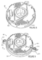
- Figure 8 is a perspective view of an encoder 80 according to an exemplary embodiment of the present invention.
- Encoder 80 includes outer diameter surface 81 having receiving grooves 82.1 and 82.2.
- the grooves 82.1, 82.2 are arranged to receive bosses 13.1, 13.2, 14.1, 14.2 therein.
- the grooves 82.1, 82.2 may have a greater angular extent than the bosses 13.1/14.2, 13.2/14.1 so that the servo cleat 20, when attached to the encoder 80, permits a certain degree of angular movement between the servo cleat 20 and the encoder, e.g., for adjustment purposes.
- a single, continuous groove around an entire circumference, or a portion thereof, may be provided in the encoder 80 instead of the two grooves 82.1, 82.2.
- more than two grooves may be provided.
- Encoder 80 also includes shaft receiver 83 arranged in the centre of encoder 80.
- Figure 9 is a perspective view of encoder 80 illustrated in Figure 8 mounted in servo cleat 20.
- Servo cleat 20 includes moulded parts 10.1 and 10.2. Moulded part 10.1 includes mounting ear 12.5, and moulded part 10.2 includes mounting ear 12.4.
- Mounting ear 12.5 includes receiving arrangement 30.1, e.g., a bore, and mounting ear 12.4 includes receiving arrangement 30.2, e.g., a bore.
- Servo cleat 20 is arranged adjacent to, and coupled to, outer diameter surface 81 of encoder 80.
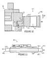
- Figure 10 is a cross-sectional view of encoder 80 and moulded part 10.1 illustrated in Figure 9 taken along line X-X.
- Figure 10 illustrates inner boss 13.2 of moulded part 10.1 received in cleat groove 82.2.
- Outer diameter surface 81 of encoder 80 abuts inner diameter surface 103 of moulded part 10.1 in the configuration illustrated in Figure 10.
- Figure 10 also illustrates recessed outer diameter surface 104 on a lower edge of outer diameter surface 81.
- Moulded part 10.1 includes mounting ear 12.5.
- Mounting ear 12.5 illustrated in cross-section includes receiving arrangement 30, e.g., a bore, outer thickness 100, and inner thickness 101.
- Outer thickness 100 is greater than inner thickness 101, causing first angle 102.1 to exist on a bottom surface of mounting ear 12.5 and second angle 102.2 to exist on a top surface of mounting ear 12.5. Because of first angle 102.1, bolting or otherwise clamping mounting ear 12.5 to a flat surface causes mounting ear 12.5 to flex upwardly on an outer diameter in the direction or arrow 105. This flexing causes pressure by inner boss 13.2 downwardly in the direction of arrow 106 on cleat groove 82.2, thereby creating a downward force on encoder 80, e.g., a force toward the motor.
- FIG 11 is a side view of encoder 80 and servo cleat 20 illustrated in Figure 10 .
- Servo cleat 20 includes moulded part 10.1 having mounting ear 12.5 and moulded part 10.2 having mounting ear 12.4.
- Mounting ear 12.5 includes first angle 102.1 and second angle 102.2 due to outer thickness 100.
- Mounting ear 12.4 may or may not also include an outer thickness greater than an inner thickness and a bottom angle and a top angle.
- Recessed outer diameter surface 104 extends below a lower edge of servo cleat 20 as shown in the configuration of Figures 10 and 11 . Recessed outer diameter surface 104 may project into a pilot of a motor or other device.
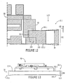
- Figure 12 is a cross-sectional view of encoder 80 and moulded part 10.1 illustrated in Figure 9 taken along line X-X with servo cleat 20 in an alternative configuration with respect to encoder 80 than the configuration illustrated in Figures 10 and 11 .
- servo cleat 20 is inverted relative to the arrangement of the servo cleat 20 illustrated in Figure 10 .
- Figure 12 illustrates inner boss 13.2 of moulded part 10.1 received in cleat groove 82.2.
- Outer diameter surface 81 of encoder 80 is exposed in the configuration illustrated in Figure 12.
- Figure 12 also illustrates recessed outer diameter surface 104 adjacent to inner diameter surface 103 of moulded part 10.1.
- Moulded part 10.1 includes mounting ear 12.5.
- Mounting ear 12.5 illustrated in cross-section includes bore 30, outer thickness 100, and inner thickness 101. Outer thickness 100 is greater than inner thickness 101, causing second angle 102.2 to exist on a bottom surface of mounting ear 12.5 and first angle 102.1 to exist on a top surface of mounting ear 12.5. Because of second angle 102.2, bolting or otherwise clamping mounting ear 12.5 to a flat surface causes mounting ear 12.5 to flex upwardly on an outer diameter in the direction or arrow 105. This flexing causes pressure by inner boss 13.2 downwardly in the direction of arrow 106 on cleat groove 82.2, thereby creating a downward force on encoder 80, e.g., a force toward the motor.
- the arrangement of the servo cleat 20 as illustrated in Figure 12 permits flushmounting, e.g., pilotless mounting, of the encoder 80.
- Figure 13 is a side view of encoder 80 and servo cleat 20 illustrated in Figure 12 .
- Servo cleat 20 includes moulded part 10.1 having mounting ear 12.5 and moulded part 10.2 having mounting ear 12.4.
- Mounting ear 12.5 includes first angle 102.1 and second angle 102.2 due to outer thickness 100.
- Mounting ear 12.4 may or may not also include an outer thickness greater than an inner thickness and a bottom angle and a top angle.
- the bottom surface of the encoder 80 and the bottom surface of servo cleat 20 are substantially flush in the configuration illustrated Figures 12 and 13 , thereby permitting the encoder 80 to be flush-mounted, e.g., pilotlessly mounted.
- the part 10 may include all or some of the mounting ears 12.1, 12.2, 12.3, 12.4 illustrated in Figure 1 and that the mounting ears 12.1, 12.2, 12.3, 12.4 are selectively removable from the part 10 depending on, e.g., the desired number and location(s) of mounting ears. Any unwanted or unnecessary mounting ears 12.1, 12.2, 12.3, 12.4 is removed before or after assembly of two parts 10 to obtain the servo cleat 20. It should also be appreciated that the mounting ears 12.1, 12.2, 12.3, 12.4 are selectively formed, e.g., moulded, during manufacture of the part 10.
Landscapes
- Physics & Mathematics (AREA)
- General Physics & Mathematics (AREA)
- Transmission And Conversion Of Sensor Element Output (AREA)
- Processing Of Color Television Signals (AREA)
Applications Claiming Priority (1)
| Application Number | Priority Date | Filing Date | Title |
|---|---|---|---|
| US11/144,182 US7470889B2 (en) | 2005-06-02 | 2005-06-02 | Servo cleat for an encoder, an encoder including a servo cleat and a system including an encoder, a motor and a servo cleat |
Publications (2)
| Publication Number | Publication Date |
|---|---|
| EP1729098A1 EP1729098A1 (en) | 2006-12-06 |
| EP1729098B1 true EP1729098B1 (en) | 2009-09-30 |
Family
ID=37026946
Family Applications (1)
| Application Number | Title | Priority Date | Filing Date |
|---|---|---|---|
| EP06007239A Not-in-force EP1729098B1 (en) | 2005-06-02 | 2006-04-06 | A servo cleat for an encoder and an encoder including a servo cleat |
Country Status (5)
| Country | Link |
|---|---|
| US (1) | US7470889B2 (enExample) |
| EP (1) | EP1729098B1 (enExample) |
| JP (1) | JP4794358B2 (enExample) |
| AT (1) | ATE444476T1 (enExample) |
| DE (1) | DE602006009436D1 (enExample) |
Families Citing this family (7)
| Publication number | Priority date | Publication date | Assignee | Title |
|---|---|---|---|---|
| DE102006056462A1 (de) * | 2006-11-28 | 2008-05-29 | Dr. Johannes Heidenhain Gmbh | Drehgeber |
| US9049344B2 (en) * | 2007-08-24 | 2015-06-02 | At&T Intellectual Property I, L.P. | Method and system for providing content |
| US7580595B1 (en) | 2008-05-09 | 2009-08-25 | Technische Universitaet Berlin | Data transmission optoelectric device |
| US8146262B1 (en) | 2009-10-21 | 2012-04-03 | The Boeing Company | Method and device for locating hole center |
| US9134142B2 (en) * | 2013-03-14 | 2015-09-15 | Charles R. Kirk | Rotary encoder with free floating flexible sensor carrier |
| CN104266667B (zh) * | 2014-09-30 | 2017-01-25 | 中国科学院西安光学精密机械研究所 | 一种光学编码器安装结构及编码器安装方法 |
| US9459083B2 (en) * | 2015-01-07 | 2016-10-04 | Seagate Technology, Llc | Positioning goniometry |
Family Cites Families (7)
| Publication number | Priority date | Publication date | Assignee | Title |
|---|---|---|---|---|
| GB556019A (en) | 1942-04-13 | 1943-09-16 | Edward Roker Robertson | Improvements relating to the mounting of instruments and other devices on a support |
| US4338517A (en) * | 1979-01-15 | 1982-07-06 | Perrine Warren L | Shaft rotation sensor |
| US5117879A (en) * | 1991-09-13 | 1992-06-02 | Payne Leslie O | Split ring router mount apparatus |
| US5407294A (en) * | 1993-04-29 | 1995-04-18 | Daido Corporation | Encoder mounting device |
| DE19641929C2 (de) * | 1996-10-11 | 2000-01-05 | Ruhlatec Industrieprodukte | Encoder |
| DE19739012A1 (de) | 1997-09-06 | 1999-03-18 | Euchner Gmbh & Co | Vorrichtung zum Befestigen eines Winkelgebers |
| US6717302B2 (en) * | 2002-07-31 | 2004-04-06 | Danaher Controls Corporation | Motor for use with a sensor |
-
2005
- 2005-06-02 US US11/144,182 patent/US7470889B2/en not_active Expired - Fee Related
-
2006
- 2006-04-06 EP EP06007239A patent/EP1729098B1/en not_active Not-in-force
- 2006-04-06 AT AT06007239T patent/ATE444476T1/de not_active IP Right Cessation
- 2006-04-06 DE DE602006009436T patent/DE602006009436D1/de active Active
- 2006-05-31 JP JP2006151202A patent/JP4794358B2/ja not_active Expired - Fee Related
Also Published As
| Publication number | Publication date |
|---|---|
| US7470889B2 (en) | 2008-12-30 |
| ATE444476T1 (de) | 2009-10-15 |
| EP1729098A1 (en) | 2006-12-06 |
| JP4794358B2 (ja) | 2011-10-19 |
| JP2006337367A (ja) | 2006-12-14 |
| DE602006009436D1 (de) | 2009-11-12 |
| US20070009323A1 (en) | 2007-01-11 |
Similar Documents
| Publication | Publication Date | Title |
|---|---|---|
| EP2277011B1 (en) | Encoder device and gapping and centring device for an encoder device | |
| US6717302B2 (en) | Motor for use with a sensor | |
| EP1729098B1 (en) | A servo cleat for an encoder and an encoder including a servo cleat | |
| WO2006035686A1 (ja) | 小型モータの光学式エンコーダ装置及びその製造方法 | |
| EP1732182B1 (en) | Connecting structure of rotary connector and steering angle sensor | |
| EP2472234B1 (en) | Sensing assembly components and methods of assembling, mounting and orientating same | |
| KR100962048B1 (ko) | 차량의 스티어링 휠의 조향각 검출용 센서장치 및 그제조방법 | |
| CN115752529A (zh) | 旋转编码器及其安装方法 | |
| KR20110027651A (ko) | 회전제한부재를 갖는 인코더 | |
| WO2012112975A2 (en) | Meter socket assembly | |
| US5743763A (en) | Industrial-type mobile electric socket and plug of easier assembling | |
| JP3248862B2 (ja) | 取付追加要素を備えた電動機 | |
| CN214480156U (zh) | 一种送丝电机用编码器结构及送丝电机 | |
| US20020158542A1 (en) | Method and system for mounting a rotor position sensor | |
| CA2166934C (en) | Improved system for selectively effecting electrical connection among a plurality of loci in a housing | |
| CN114667647A (zh) | 配电自动化设备 | |
| CN222439932U (zh) | 一种压片式磁感应编码器及电子器件 | |
| CN218633612U (zh) | 编码器安装结构及电机 | |
| JP7709116B2 (ja) | 基板搭載構造 | |
| CN211737997U (zh) | P挡识别装置和车辆变速箱以及车辆 | |
| US20040052010A1 (en) | Electrical part prevented from improper mounting on circuit board, and mounting structure for the electrical part | |
| JP2006339107A (ja) | 回転コネクタと舵角センサの連結構造 | |
| US20070047201A1 (en) | Fan with an arranging device for cable thereof | |
| EP3649830B1 (en) | A cooking hob comprising a heating element provided with a fastening system | |
| CN108674181B (zh) | 一种电子踏板结构 |
Legal Events
| Date | Code | Title | Description |
|---|---|---|---|
| PUAI | Public reference made under article 153(3) epc to a published international application that has entered the european phase |
Free format text: ORIGINAL CODE: 0009012 |
|
| AK | Designated contracting states |
Kind code of ref document: A1 Designated state(s): AT BE BG CH CY CZ DE DK EE ES FI FR GB GR HU IE IS IT LI LT LU LV MC NL PL PT RO SE SI SK TR |
|
| AX | Request for extension of the european patent |
Extension state: AL BA HR MK YU |
|
| 17P | Request for examination filed |
Effective date: 20070606 |
|
| AKX | Designation fees paid |
Designated state(s): AT BE BG CH CY CZ DE DK EE ES FI FR GB GR HU IE IS IT LI LT LU LV MC NL PL PT RO SE SI SK TR |
|
| 17Q | First examination report despatched |
Effective date: 20070724 |
|
| GRAP | Despatch of communication of intention to grant a patent |
Free format text: ORIGINAL CODE: EPIDOSNIGR1 |
|
| GRAS | Grant fee paid |
Free format text: ORIGINAL CODE: EPIDOSNIGR3 |
|
| GRAA | (expected) grant |
Free format text: ORIGINAL CODE: 0009210 |
|
| AK | Designated contracting states |
Kind code of ref document: B1 Designated state(s): AT BE BG CH CY CZ DE DK EE ES FI FR GB GR HU IE IS IT LI LT LU LV MC NL PL PT RO SE SI SK TR |
|
| REG | Reference to a national code |
Ref country code: GB Ref legal event code: FG4D Ref country code: CH Ref legal event code: EP |
|
| REG | Reference to a national code |
Ref country code: IE Ref legal event code: FG4D |
|
| REF | Corresponds to: |
Ref document number: 602006009436 Country of ref document: DE Date of ref document: 20091112 Kind code of ref document: P |
|
| PG25 | Lapsed in a contracting state [announced via postgrant information from national office to epo] |
Ref country code: SE Free format text: LAPSE BECAUSE OF FAILURE TO SUBMIT A TRANSLATION OF THE DESCRIPTION OR TO PAY THE FEE WITHIN THE PRESCRIBED TIME-LIMIT Effective date: 20090930 Ref country code: LT Free format text: LAPSE BECAUSE OF FAILURE TO SUBMIT A TRANSLATION OF THE DESCRIPTION OR TO PAY THE FEE WITHIN THE PRESCRIBED TIME-LIMIT Effective date: 20090930 Ref country code: FI Free format text: LAPSE BECAUSE OF FAILURE TO SUBMIT A TRANSLATION OF THE DESCRIPTION OR TO PAY THE FEE WITHIN THE PRESCRIBED TIME-LIMIT Effective date: 20090930 |
|
| LTIE | Lt: invalidation of european patent or patent extension |
Effective date: 20090930 |
|
| PG25 | Lapsed in a contracting state [announced via postgrant information from national office to epo] |
Ref country code: PL Free format text: LAPSE BECAUSE OF FAILURE TO SUBMIT A TRANSLATION OF THE DESCRIPTION OR TO PAY THE FEE WITHIN THE PRESCRIBED TIME-LIMIT Effective date: 20090930 Ref country code: SI Free format text: LAPSE BECAUSE OF FAILURE TO SUBMIT A TRANSLATION OF THE DESCRIPTION OR TO PAY THE FEE WITHIN THE PRESCRIBED TIME-LIMIT Effective date: 20090930 Ref country code: LV Free format text: LAPSE BECAUSE OF FAILURE TO SUBMIT A TRANSLATION OF THE DESCRIPTION OR TO PAY THE FEE WITHIN THE PRESCRIBED TIME-LIMIT Effective date: 20090930 |
|
| NLV1 | Nl: lapsed or annulled due to failure to fulfill the requirements of art. 29p and 29m of the patents act | ||
| PG25 | Lapsed in a contracting state [announced via postgrant information from national office to epo] |
Ref country code: PT Free format text: LAPSE BECAUSE OF FAILURE TO SUBMIT A TRANSLATION OF THE DESCRIPTION OR TO PAY THE FEE WITHIN THE PRESCRIBED TIME-LIMIT Effective date: 20100201 Ref country code: RO Free format text: LAPSE BECAUSE OF FAILURE TO SUBMIT A TRANSLATION OF THE DESCRIPTION OR TO PAY THE FEE WITHIN THE PRESCRIBED TIME-LIMIT Effective date: 20090930 Ref country code: ES Free format text: LAPSE BECAUSE OF FAILURE TO SUBMIT A TRANSLATION OF THE DESCRIPTION OR TO PAY THE FEE WITHIN THE PRESCRIBED TIME-LIMIT Effective date: 20100110 Ref country code: EE Free format text: LAPSE BECAUSE OF FAILURE TO SUBMIT A TRANSLATION OF THE DESCRIPTION OR TO PAY THE FEE WITHIN THE PRESCRIBED TIME-LIMIT Effective date: 20090930 Ref country code: IS Free format text: LAPSE BECAUSE OF FAILURE TO SUBMIT A TRANSLATION OF THE DESCRIPTION OR TO PAY THE FEE WITHIN THE PRESCRIBED TIME-LIMIT Effective date: 20100130 |
|
| PG25 | Lapsed in a contracting state [announced via postgrant information from national office to epo] |
Ref country code: CY Free format text: LAPSE BECAUSE OF FAILURE TO SUBMIT A TRANSLATION OF THE DESCRIPTION OR TO PAY THE FEE WITHIN THE PRESCRIBED TIME-LIMIT Effective date: 20090930 Ref country code: SK Free format text: LAPSE BECAUSE OF FAILURE TO SUBMIT A TRANSLATION OF THE DESCRIPTION OR TO PAY THE FEE WITHIN THE PRESCRIBED TIME-LIMIT Effective date: 20090930 |
|
| PG25 | Lapsed in a contracting state [announced via postgrant information from national office to epo] |
Ref country code: BE Free format text: LAPSE BECAUSE OF FAILURE TO SUBMIT A TRANSLATION OF THE DESCRIPTION OR TO PAY THE FEE WITHIN THE PRESCRIBED TIME-LIMIT Effective date: 20090930 Ref country code: AT Free format text: LAPSE BECAUSE OF FAILURE TO SUBMIT A TRANSLATION OF THE DESCRIPTION OR TO PAY THE FEE WITHIN THE PRESCRIBED TIME-LIMIT Effective date: 20090930 |
|
| PG25 | Lapsed in a contracting state [announced via postgrant information from national office to epo] |
Ref country code: DK Free format text: LAPSE BECAUSE OF FAILURE TO SUBMIT A TRANSLATION OF THE DESCRIPTION OR TO PAY THE FEE WITHIN THE PRESCRIBED TIME-LIMIT Effective date: 20090930 Ref country code: NL Free format text: LAPSE BECAUSE OF FAILURE TO SUBMIT A TRANSLATION OF THE DESCRIPTION OR TO PAY THE FEE WITHIN THE PRESCRIBED TIME-LIMIT Effective date: 20090930 |
|
| PLBE | No opposition filed within time limit |
Free format text: ORIGINAL CODE: 0009261 |
|
| STAA | Information on the status of an ep patent application or granted ep patent |
Free format text: STATUS: NO OPPOSITION FILED WITHIN TIME LIMIT |
|
| 26N | No opposition filed |
Effective date: 20100701 |
|
| PG25 | Lapsed in a contracting state [announced via postgrant information from national office to epo] |
Ref country code: GR Free format text: LAPSE BECAUSE OF FAILURE TO SUBMIT A TRANSLATION OF THE DESCRIPTION OR TO PAY THE FEE WITHIN THE PRESCRIBED TIME-LIMIT Effective date: 20091231 |
|
| PG25 | Lapsed in a contracting state [announced via postgrant information from national office to epo] |
Ref country code: MC Free format text: LAPSE BECAUSE OF NON-PAYMENT OF DUE FEES Effective date: 20100430 |
|
| REG | Reference to a national code |
Ref country code: CH Ref legal event code: PL |
|
| REG | Reference to a national code |
Ref country code: FR Ref legal event code: ST Effective date: 20101230 |
|
| PG25 | Lapsed in a contracting state [announced via postgrant information from national office to epo] |
Ref country code: IE Free format text: LAPSE BECAUSE OF NON-PAYMENT OF DUE FEES Effective date: 20100406 |
|
| PG25 | Lapsed in a contracting state [announced via postgrant information from national office to epo] |
Ref country code: LI Free format text: LAPSE BECAUSE OF NON-PAYMENT OF DUE FEES Effective date: 20100430 Ref country code: CH Free format text: LAPSE BECAUSE OF NON-PAYMENT OF DUE FEES Effective date: 20100430 |
|
| PG25 | Lapsed in a contracting state [announced via postgrant information from national office to epo] |
Ref country code: FR Free format text: LAPSE BECAUSE OF NON-PAYMENT OF DUE FEES Effective date: 20100430 |
|
| PG25 | Lapsed in a contracting state [announced via postgrant information from national office to epo] |
Ref country code: HU Free format text: LAPSE BECAUSE OF FAILURE TO SUBMIT A TRANSLATION OF THE DESCRIPTION OR TO PAY THE FEE WITHIN THE PRESCRIBED TIME-LIMIT Effective date: 20100401 Ref country code: LU Free format text: LAPSE BECAUSE OF NON-PAYMENT OF DUE FEES Effective date: 20100406 Ref country code: BG Free format text: LAPSE BECAUSE OF FAILURE TO SUBMIT A TRANSLATION OF THE DESCRIPTION OR TO PAY THE FEE WITHIN THE PRESCRIBED TIME-LIMIT Effective date: 20090930 |
|
| PG25 | Lapsed in a contracting state [announced via postgrant information from national office to epo] |
Ref country code: TR Free format text: LAPSE BECAUSE OF FAILURE TO SUBMIT A TRANSLATION OF THE DESCRIPTION OR TO PAY THE FEE WITHIN THE PRESCRIBED TIME-LIMIT Effective date: 20090930 |
|
| PGFP | Annual fee paid to national office [announced via postgrant information from national office to epo] |
Ref country code: CZ Payment date: 20160405 Year of fee payment: 11 Ref country code: GB Payment date: 20160421 Year of fee payment: 11 |
|
| PGFP | Annual fee paid to national office [announced via postgrant information from national office to epo] |
Ref country code: IT Payment date: 20160427 Year of fee payment: 11 |
|
| PG25 | Lapsed in a contracting state [announced via postgrant information from national office to epo] |
Ref country code: CZ Free format text: LAPSE BECAUSE OF NON-PAYMENT OF DUE FEES Effective date: 20170406 |
|
| GBPC | Gb: european patent ceased through non-payment of renewal fee |
Effective date: 20170406 |
|
| PG25 | Lapsed in a contracting state [announced via postgrant information from national office to epo] |
Ref country code: GB Free format text: LAPSE BECAUSE OF NON-PAYMENT OF DUE FEES Effective date: 20170406 |
|
| PG25 | Lapsed in a contracting state [announced via postgrant information from national office to epo] |
Ref country code: IT Free format text: LAPSE BECAUSE OF NON-PAYMENT OF DUE FEES Effective date: 20170406 |
|
| PGFP | Annual fee paid to national office [announced via postgrant information from national office to epo] |
Ref country code: DE Payment date: 20200420 Year of fee payment: 15 |
|
| REG | Reference to a national code |
Ref country code: DE Ref legal event code: R119 Ref document number: 602006009436 Country of ref document: DE |
|
| PG25 | Lapsed in a contracting state [announced via postgrant information from national office to epo] |
Ref country code: DE Free format text: LAPSE BECAUSE OF NON-PAYMENT OF DUE FEES Effective date: 20211103 |