EP1729012A2 - Zentrifugal-Gebläserad - Google Patents
Zentrifugal-Gebläserad Download PDFInfo
- Publication number
- EP1729012A2 EP1729012A2 EP06075899A EP06075899A EP1729012A2 EP 1729012 A2 EP1729012 A2 EP 1729012A2 EP 06075899 A EP06075899 A EP 06075899A EP 06075899 A EP06075899 A EP 06075899A EP 1729012 A2 EP1729012 A2 EP 1729012A2
- Authority
- EP
- European Patent Office
- Prior art keywords
- blades
- series
- suction device
- impeller
- inlet opening
- Prior art date
- Legal status (The legal status is an assumption and is not a legal conclusion. Google has not performed a legal analysis and makes no representation as to the accuracy of the status listed.)
- Granted
Links
Images

Classifications
-
- F—MECHANICAL ENGINEERING; LIGHTING; HEATING; WEAPONS; BLASTING
- F04—POSITIVE - DISPLACEMENT MACHINES FOR LIQUIDS; PUMPS FOR LIQUIDS OR ELASTIC FLUIDS
- F04D—NON-POSITIVE-DISPLACEMENT PUMPS
- F04D29/00—Details, component parts, or accessories
- F04D29/26—Rotors specially for elastic fluids
- F04D29/28—Rotors specially for elastic fluids for centrifugal or helico-centrifugal pumps for radial-flow or helico-centrifugal pumps
- F04D29/281—Rotors specially for elastic fluids for centrifugal or helico-centrifugal pumps for radial-flow or helico-centrifugal pumps for fans or blowers
-
- F—MECHANICAL ENGINEERING; LIGHTING; HEATING; WEAPONS; BLASTING
- F04—POSITIVE - DISPLACEMENT MACHINES FOR LIQUIDS; PUMPS FOR LIQUIDS OR ELASTIC FLUIDS
- F04D—NON-POSITIVE-DISPLACEMENT PUMPS
- F04D17/00—Radial-flow pumps, e.g. centrifugal pumps; Helico-centrifugal pumps
- F04D17/02—Radial-flow pumps, e.g. centrifugal pumps; Helico-centrifugal pumps having non-centrifugal stages, e.g. centripetal
- F04D17/025—Radial-flow pumps, e.g. centrifugal pumps; Helico-centrifugal pumps having non-centrifugal stages, e.g. centripetal comprising axial flow and radial flow stages
Definitions
- the present invention refers to a portable suction device for cleaning jobs.
- the present invention refers to a portable suction device suitable for sucking up sawdust, leaves, grass cuttings and similar for cleaning jobs at rural and/or urban locations.
- common portable suction devices comprise an impeller with centrally closed disc fitted on a drive shaft suitable for making it rotate inside a closed housing provided with an air inlet opening with which a suction mouth is associated and an outlet opening with which a collection sack is associated.
- Portable suction devices of the prior art comprise an impeller having a plurality of blades with radial flow arranged close together so as to generate a sufficient static flow to overcome the load loss due to the collection sack for the material that has been sucked up.
- These blades inevitably have an unsuitable attachment angle near to the suction opening where the predominant flow direction is axial to the impeller, whereas the motion of the blades is in a tangential direction. This means low efficiency and lots of noise during use. Therefore, there is a great need to have a suction device for cleaning jobs that has high efficiency and that produces little noise.
- the purpose of the present invention is that of providing a suction device having structural and functional characteristics such as to satisfy the aforementioned requirements and at the same time to avoid the aforementioned drawbacks with reference to the prior art. Such a purpose is accomplished through a suction device in accordance with claim 1.
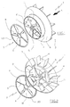
- an impeller for a suction device (Fig. 6) in accordance with the present invention is globally indicated with 1.
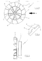
- the suction device in brief comprises an impeller 1, a motor for actuating the impeller 1 that is fitted centrally to the drive shaft, a carcass 50 (Fig. 6) for containing the impeller 1 provided with an inlet opening with which a suction mouth 60 is associated and an outlet opening with which a collection sack 70 is associated.
- the impeller 1 comprises a first series of blades, globally indicated with 2, and a second series of blades, globally indicated with 3, coaxial to each other and distributed in a staggered manner.
- the first series of blades 2 is suitable for generating an axial flow whereas the second series of blades 3 is suitable for generating a radial flow.
- the second series of blades 3 is arranged downstream of the first series of blades 2, with respect to the inlet opening, i.e. with respect to the side of attachment of the suction mouth.
- the arrangement of the blade sets 2 and 3 is selected so that the air sucked in reaches first the first series of blades 2 that transmits it to the second series of blades 3 before it reaches the outlet opening and then the collection sack 70.
- the impeller 1 comprises a hollow cylindrical body 4 inside which the first series of blades 2 is formed, said blades projecting from a common central hub 5, suitable for being fitted onto the drive shaft.
- a circular crown 6 carrying the second series of blades 3 is coaxially fixed, said blades being staggered with respect to those of the first series 2.
- the circular crown 6 has a frusto-conical configuration with the smaller base fixed firmly to the edge of the cylindrical body 4.
- the airflow is "helped" in the passage from axial motion to radial motion, i.e. in the passage from the first series of blades 2 to the second series of blades 3 by making the surface of the circular crown 6 with a curvature having the concavity facing outwards.
- the blades of the second series of blades 3 are arranged on the surface of the circular crown 6 opposite that for the inlet of the airflow, i.e. on the convex side.
- the number of blades in the first series of blades 2 is less than in the second series of blades 3; in the example the first series of blades 2 consists of four blades, whereas the second series of blades 3 consists of eleven blades.
- the particular configuration of the blades is selected according to the intended use of the suction device and according to current knowledge in the field.
- the impeller 1 of the present invention can be easily obtained through known plastic forming processes.
- Each protective element 8 is in the form of a pair of concentric circular rings 10, 100 with the protective elements 8 fanning out between them.
- the inner ring 10 is suitable for cooperating in engagement with the hub 5 and the outer ring 100 is suitable for cooperating in engagement with the edge of the circular body 4.
- Each protective element 8 is provided with an appendix 9 suitable for snap-engaging in a corresponding slot 11 formed on each blade of the first series of blades 2.
- the suction device according to the present invention allows the requirements to be satisfied and allows the drawbacks mentioned in the introductory part of the present description with reference to the prior art to be overcome.
Applications Claiming Priority (1)
| Application Number | Priority Date | Filing Date | Title |
|---|---|---|---|
| IT000060A ITRE20050060A1 (it) | 2005-05-26 | 2005-05-26 | Aspiratore portatile per lavori di pulizia |
Publications (3)
| Publication Number | Publication Date |
|---|---|
| EP1729012A2 true EP1729012A2 (de) | 2006-12-06 |
| EP1729012A3 EP1729012A3 (de) | 2010-03-10 |
| EP1729012B1 EP1729012B1 (de) | 2011-05-11 |
Family
ID=36997482
Family Applications (1)
| Application Number | Title | Priority Date | Filing Date |
|---|---|---|---|
| EP06075899A Expired - Fee Related EP1729012B1 (de) | 2005-05-26 | 2006-04-18 | Zentrifugal-Gebläserad |
Country Status (4)
| Country | Link |
|---|---|
| US (1) | US7788764B2 (de) |
| EP (1) | EP1729012B1 (de) |
| AU (1) | AU2006201641B2 (de) |
| IT (1) | ITRE20050060A1 (de) |
Cited By (4)
| Publication number | Priority date | Publication date | Assignee | Title |
|---|---|---|---|---|
| EP2546526A1 (de) * | 2011-07-14 | 2013-01-16 | Black & Decker Inc. | Antriebsanordnung |
| CN105570192A (zh) * | 2016-02-29 | 2016-05-11 | 李锦标 | 一种风机叶轮及其加工方法 |
| CN107288084A (zh) * | 2017-06-16 | 2017-10-24 | 宁波大叶园林设备股份有限公司 | 带组合前风筒吸声消声及后风筒多管消声的吹叶机 |
| CN110848157A (zh) * | 2019-11-20 | 2020-02-28 | 泛仕达机电股份有限公司 | 一种多层离心叶轮及应用该多层离心叶轮的风机 |
Families Citing this family (5)
| Publication number | Priority date | Publication date | Assignee | Title |
|---|---|---|---|---|
| US20080276416A1 (en) * | 2007-05-08 | 2008-11-13 | Husqvarna Outdoor Products Inc. | Tube barrier |
| WO2008154682A1 (en) * | 2007-06-18 | 2008-12-24 | Roy Gripske & Sons Pty Ltd | An apparatus for use in gathering debris by applying a vacuum |
| IT1393872B1 (it) * | 2009-04-22 | 2012-05-11 | Ansaldo Ricerche S P A | Sistema di raffreddamento per motore elettrico ad alta densita' volumetrica di potenza, in particolare motore elettrico a flusso assiale |
| RU2553596C1 (ru) * | 2014-06-25 | 2015-06-20 | Федеральное государственное бюджетное образовательное учреждение высшего профессионального образования "Иркутская государственная сельскохозяйственная академия" | Осевой вентилятор с центробежными лопатками |
| US10125790B2 (en) * | 2014-07-24 | 2018-11-13 | Mahle International Gmbh | Centrifugal fan with reduced motor cooling noise |
Citations (1)
| Publication number | Priority date | Publication date | Assignee | Title |
|---|---|---|---|---|
| DE19946187A1 (de) | 1998-12-18 | 2000-06-29 | Echo Incorp | Transportables Gebläse für fliessfähige Medien |
Family Cites Families (9)
| Publication number | Priority date | Publication date | Assignee | Title |
|---|---|---|---|---|
| US2982986A (en) * | 1956-09-19 | 1961-05-09 | Gen Electric | Vacuum cleaner with improved fan arrangement |
| US4644606A (en) * | 1985-04-08 | 1987-02-24 | Mcculloch Corporation | Lawn/garden blower/vacuum |
| JP3675115B2 (ja) * | 1997-07-11 | 2005-07-27 | 株式会社日立製作所 | 電動送風機及びこの電動送風機に用いる羽根車の製造方法 |
| US6059541A (en) * | 1998-03-10 | 2000-05-09 | The Toro Company | Air inlet cover for portable blower/vacuum |
| US6736610B2 (en) * | 1999-07-30 | 2004-05-18 | Cifarelli S.P.A. | Blower fan, in particular for blowing apparatuses, and blowing apparatus provided thereof |
| US6386839B1 (en) * | 2000-12-28 | 2002-05-14 | Wen-Hao Chuang | High performance radiator fan |
| US6442790B1 (en) * | 2001-02-09 | 2002-09-03 | The Toro Company | Portable blower/vacuum having air inlet cover attachable to blower tube |
| AT414064B (de) * | 2001-05-11 | 2006-08-15 | Tcg Unitech Ag | Pumpe für flüssige medien |
| TWI235205B (en) * | 2003-10-31 | 2005-07-01 | Delta Electronics Inc | Centrifugal fan with stator blades |
-
2005
- 2005-05-26 IT IT000060A patent/ITRE20050060A1/it unknown
-
2006
- 2006-04-18 EP EP06075899A patent/EP1729012B1/de not_active Expired - Fee Related
- 2006-04-20 AU AU2006201641A patent/AU2006201641B2/en not_active Expired - Fee Related
- 2006-05-17 US US11/434,926 patent/US7788764B2/en not_active Expired - Fee Related
Patent Citations (1)
| Publication number | Priority date | Publication date | Assignee | Title |
|---|---|---|---|---|
| DE19946187A1 (de) | 1998-12-18 | 2000-06-29 | Echo Incorp | Transportables Gebläse für fliessfähige Medien |
Cited By (4)
| Publication number | Priority date | Publication date | Assignee | Title |
|---|---|---|---|---|
| EP2546526A1 (de) * | 2011-07-14 | 2013-01-16 | Black & Decker Inc. | Antriebsanordnung |
| CN105570192A (zh) * | 2016-02-29 | 2016-05-11 | 李锦标 | 一种风机叶轮及其加工方法 |
| CN107288084A (zh) * | 2017-06-16 | 2017-10-24 | 宁波大叶园林设备股份有限公司 | 带组合前风筒吸声消声及后风筒多管消声的吹叶机 |
| CN110848157A (zh) * | 2019-11-20 | 2020-02-28 | 泛仕达机电股份有限公司 | 一种多层离心叶轮及应用该多层离心叶轮的风机 |
Also Published As
| Publication number | Publication date |
|---|---|
| AU2006201641B2 (en) | 2010-11-11 |
| EP1729012A3 (de) | 2010-03-10 |
| US7788764B2 (en) | 2010-09-07 |
| US20060265833A1 (en) | 2006-11-30 |
| AU2006201641A1 (en) | 2006-12-14 |
| ITRE20050060A1 (it) | 2006-11-27 |
| EP1729012B1 (de) | 2011-05-11 |
Similar Documents
| Publication | Publication Date | Title |
|---|---|---|
| EP1729012A2 (de) | Zentrifugal-Gebläserad | |
| US4407112A (en) | Grass mower | |
| TWI394895B (zh) | Centrifugal fans and air fluid machinery using the centrifugal fan | |
| CN102878115B (zh) | 碎屑吹扫和/或抽吸装置 | |
| ATE413533T1 (de) | Schaufelrad für zentrifugalgebläse und zentrifugalgebläse damit | |
| JPH09328729A (ja) | 吹き出し及び吸引装置、特に、木の葉等の収集と粉砕のための吸引切断機 | |
| ATE502217T1 (de) | Lüfter | |
| JP2007518933A5 (de) | ||
| US5794864A (en) | Portable lawn and garden mulching vacuum | |
| CN205154744U (zh) | 离心式涡轮风叶及应用其的电机和食品搅拌机 | |
| US2325221A (en) | Segregated pressure fan | |
| EP3779203B1 (de) | Lüfterzusammenbau für bodenkehrroboter sowie bodenkehrroboter | |
| KR20050078873A (ko) | 청소기의 송풍장치 | |
| JP2007315399A (ja) | 多段形テーパファン−モータアセンブリ | |
| GB2090338A (en) | Centrifugal fan | |
| JP4448929B2 (ja) | 可搬式のブロワ | |
| CN209115392U (zh) | 吸油烟机风机及其离心式叶轮 | |
| JP2011064096A (ja) | 電動送風機及びこれを用いた電気掃除機 | |
| EP0843102A3 (de) | Lüfter mit erhöhter Schaufeloberfläche | |
| US20060093479A1 (en) | Pressure-boosting axial-flow heat-dissipating fan | |
| CN100353077C (zh) | 轴流风扇的出风构造 | |
| EP2536956B1 (de) | Elektrische zentrifugalpumpe zur ansaugung von gasförmigen flüssigkeiten mit einer dämpfervorrichtung | |
| JP4253902B2 (ja) | 多翼遠心ファン | |
| CN207033834U (zh) | 轴流风扇及电动工具 | |
| CN207295589U (zh) | 一种带风道清洁和蜗壳保护的吹吸机 |
Legal Events
| Date | Code | Title | Description |
|---|---|---|---|
| PUAI | Public reference made under article 153(3) epc to a published international application that has entered the european phase |
Free format text: ORIGINAL CODE: 0009012 |
|
| AK | Designated contracting states |
Kind code of ref document: A2 Designated state(s): AT BE BG CH CY CZ DE DK EE ES FI FR GB GR HU IE IS IT LI LT LU LV MC NL PL PT RO SE SI SK TR |
|
| AX | Request for extension of the european patent |
Extension state: AL BA HR MK YU |
|
| PUAL | Search report despatched |
Free format text: ORIGINAL CODE: 0009013 |
|
| AK | Designated contracting states |
Kind code of ref document: A3 Designated state(s): AT BE BG CH CY CZ DE DK EE ES FI FR GB GR HU IE IS IT LI LT LU LV MC NL PL PT RO SE SI SK TR |
|
| AX | Request for extension of the european patent |
Extension state: AL BA HR MK YU |
|
| 17P | Request for examination filed |
Effective date: 20100906 |
|
| AKX | Designation fees paid |
Designated state(s): DE FR IT |
|
| GRAJ | Information related to disapproval of communication of intention to grant by the applicant or resumption of examination proceedings by the epo deleted |
Free format text: ORIGINAL CODE: EPIDOSDIGR1 |
|
| GRAP | Despatch of communication of intention to grant a patent |
Free format text: ORIGINAL CODE: EPIDOSNIGR1 |
|
| GRAS | Grant fee paid |
Free format text: ORIGINAL CODE: EPIDOSNIGR3 |
|
| GRAA | (expected) grant |
Free format text: ORIGINAL CODE: 0009210 |
|
| AK | Designated contracting states |
Kind code of ref document: B1 Designated state(s): DE FR IT |
|
| REG | Reference to a national code |
Ref country code: DE Ref legal event code: R096 Ref document number: 602006021825 Country of ref document: DE Effective date: 20110622 |
|
| PLBE | No opposition filed within time limit |
Free format text: ORIGINAL CODE: 0009261 |
|
| STAA | Information on the status of an ep patent application or granted ep patent |
Free format text: STATUS: NO OPPOSITION FILED WITHIN TIME LIMIT |
|
| 26N | No opposition filed |
Effective date: 20120214 |
|
| REG | Reference to a national code |
Ref country code: DE Ref legal event code: R097 Ref document number: 602006021825 Country of ref document: DE Effective date: 20120214 |
|
| PGFP | Annual fee paid to national office [announced via postgrant information from national office to epo] |
Ref country code: IT Payment date: 20120327 Year of fee payment: 7 |
|
| PGFP | Annual fee paid to national office [announced via postgrant information from national office to epo] |
Ref country code: DE Payment date: 20130429 Year of fee payment: 8 |
|
| PGFP | Annual fee paid to national office [announced via postgrant information from national office to epo] |
Ref country code: FR Payment date: 20130506 Year of fee payment: 8 |
|
| PG25 | Lapsed in a contracting state [announced via postgrant information from national office to epo] |
Ref country code: IT Free format text: LAPSE BECAUSE OF NON-PAYMENT OF DUE FEES Effective date: 20130418 |
|
| REG | Reference to a national code |
Ref country code: DE Ref legal event code: R119 Ref document number: 602006021825 Country of ref document: DE |
|
| REG | Reference to a national code |
Ref country code: DE Ref legal event code: R119 Ref document number: 602006021825 Country of ref document: DE Effective date: 20141101 |
|
| REG | Reference to a national code |
Ref country code: FR Ref legal event code: ST Effective date: 20141231 |
|
| PG25 | Lapsed in a contracting state [announced via postgrant information from national office to epo] |
Ref country code: DE Free format text: LAPSE BECAUSE OF NON-PAYMENT OF DUE FEES Effective date: 20141101 |
|
| PG25 | Lapsed in a contracting state [announced via postgrant information from national office to epo] |
Ref country code: FR Free format text: LAPSE BECAUSE OF NON-PAYMENT OF DUE FEES Effective date: 20140430 |