EP1728987A1 - Kühlvorrichtung für einen PKW, Motorlüfter für eine derartige Vorrichtung und der entsprechende PKW - Google Patents
Kühlvorrichtung für einen PKW, Motorlüfter für eine derartige Vorrichtung und der entsprechende PKW Download PDFInfo
- Publication number
- EP1728987A1 EP1728987A1 EP20060300540 EP06300540A EP1728987A1 EP 1728987 A1 EP1728987 A1 EP 1728987A1 EP 20060300540 EP20060300540 EP 20060300540 EP 06300540 A EP06300540 A EP 06300540A EP 1728987 A1 EP1728987 A1 EP 1728987A1
- Authority
- EP
- European Patent Office
- Prior art keywords
- air
- propeller
- cooling device
- fin
- peripheral region
- Prior art date
- Legal status (The legal status is an assumption and is not a legal conclusion. Google has not performed a legal analysis and makes no representation as to the accuracy of the status listed.)
- Granted
Links
Images


Classifications
-
- F—MECHANICAL ENGINEERING; LIGHTING; HEATING; WEAPONS; BLASTING
- F01—MACHINES OR ENGINES IN GENERAL; ENGINE PLANTS IN GENERAL; STEAM ENGINES
- F01P—COOLING OF MACHINES OR ENGINES IN GENERAL; COOLING OF INTERNAL-COMBUSTION ENGINES
- F01P11/00—Component parts, details, or accessories not provided for in, or of interest apart from, groups F01P1/00 - F01P9/00
- F01P11/10—Guiding or ducting cooling-air, to, or from, liquid-to-air heat exchangers
-
- F—MECHANICAL ENGINEERING; LIGHTING; HEATING; WEAPONS; BLASTING
- F01—MACHINES OR ENGINES IN GENERAL; ENGINE PLANTS IN GENERAL; STEAM ENGINES
- F01P—COOLING OF MACHINES OR ENGINES IN GENERAL; COOLING OF INTERNAL-COMBUSTION ENGINES
- F01P1/00—Air cooling
- F01P1/06—Arrangements for cooling other engine or machine parts
-
- F—MECHANICAL ENGINEERING; LIGHTING; HEATING; WEAPONS; BLASTING
- F01—MACHINES OR ENGINES IN GENERAL; ENGINE PLANTS IN GENERAL; STEAM ENGINES
- F01P—COOLING OF MACHINES OR ENGINES IN GENERAL; COOLING OF INTERNAL-COMBUSTION ENGINES
- F01P5/00—Pumping cooling-air or liquid coolants
- F01P5/02—Pumping cooling-air; Arrangements of cooling-air pumps, e.g. fans or blowers
- F01P5/06—Guiding or ducting air to, or from, ducted fans
-
- F—MECHANICAL ENGINEERING; LIGHTING; HEATING; WEAPONS; BLASTING
- F04—POSITIVE - DISPLACEMENT MACHINES FOR LIQUIDS; PUMPS FOR LIQUIDS OR ELASTIC FLUIDS
- F04D—NON-POSITIVE-DISPLACEMENT PUMPS
- F04D29/00—Details, component parts, or accessories
- F04D29/08—Sealings
- F04D29/16—Sealings between pressure and suction sides
- F04D29/161—Sealings between pressure and suction sides especially adapted for elastic fluid pumps
- F04D29/164—Sealings between pressure and suction sides especially adapted for elastic fluid pumps of an axial flow wheel
-
- F—MECHANICAL ENGINEERING; LIGHTING; HEATING; WEAPONS; BLASTING
- F04—POSITIVE - DISPLACEMENT MACHINES FOR LIQUIDS; PUMPS FOR LIQUIDS OR ELASTIC FLUIDS
- F04D—NON-POSITIVE-DISPLACEMENT PUMPS
- F04D29/00—Details, component parts, or accessories
- F04D29/26—Rotors specially for elastic fluids
- F04D29/32—Rotors specially for elastic fluids for axial flow pumps
- F04D29/325—Rotors specially for elastic fluids for axial flow pumps for axial flow fans
- F04D29/326—Rotors specially for elastic fluids for axial flow pumps for axial flow fans comprising a rotating shroud
-
- F—MECHANICAL ENGINEERING; LIGHTING; HEATING; WEAPONS; BLASTING
- F04—POSITIVE - DISPLACEMENT MACHINES FOR LIQUIDS; PUMPS FOR LIQUIDS OR ELASTIC FLUIDS
- F04D—NON-POSITIVE-DISPLACEMENT PUMPS
- F04D29/00—Details, component parts, or accessories
- F04D29/26—Rotors specially for elastic fluids
- F04D29/32—Rotors specially for elastic fluids for axial flow pumps
- F04D29/38—Blades
- F04D29/384—Blades characterised by form
-
- F—MECHANICAL ENGINEERING; LIGHTING; HEATING; WEAPONS; BLASTING
- F05—INDEXING SCHEMES RELATING TO ENGINES OR PUMPS IN VARIOUS SUBCLASSES OF CLASSES F01-F04
- F05D—INDEXING SCHEME FOR ASPECTS RELATING TO NON-POSITIVE-DISPLACEMENT MACHINES OR ENGINES, GAS-TURBINES OR JET-PROPULSION PLANTS
- F05D2240/00—Components
- F05D2240/20—Rotors
- F05D2240/30—Characteristics of rotor blades, i.e. of any element transforming dynamic fluid energy to or from rotational energy and being attached to a rotor
- F05D2240/307—Characteristics of rotor blades, i.e. of any element transforming dynamic fluid energy to or from rotational energy and being attached to a rotor related to the tip of a rotor blade
Definitions
- the present invention relates to a cooling device for a motor vehicle, of the type comprising a heat exchanger, and a motor-fan unit comprising a motorized propeller, arranged to rotate about an axis, facing the exchanger, and intended for aspirate, during operation of the propeller, air through the heat exchanger.
- the heat exchanger is for example a radiator of a cooling circuit of a thermal engine of the motor vehicle, an air conditioning circuit of the passenger compartment of the motor vehicle, or an air cooling circuit of supercharging of the combustion engine of the motor vehicle.
- motor vehicles comprise elements which it is desirable to cool to improve their operation.
- These elements are, for example, an electronic box housed inside the engine compartment, or the brakes of the motor vehicle.
- the air drawn by the propeller is warmed as it passes through the heat exchanger. Therefore, this hot air can not be used to satisfactorily cool such elements.
- An object of the invention is to provide a cooling device for effectively cooling remote elements of the heat exchanger.
- the present invention proposes a cooling device of the aforementioned type, characterized in that the helix comprises a peripheral region protruding, in at least one angular sector, from the periphery of the exchanger for capturing air in outside the exchanger, the motor-fan unit comprising elements for channeling the air captured by the peripheral region, the peripheral region being profiled so as to form a flow of air flowing mainly parallel to the axis of rotation of the propeller.
- the invention also relates to a motor-fan unit for a cooling device as defined above, comprising the air channeling elements, and the motorized propeller.
- the invention also relates to a motor vehicle comprising a cooling device as defined above.
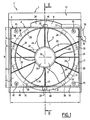
- the cooling device 2 comprises a heat exchanger 4 (represented only by its outline in phantom in FIG. 1) and a motor-fan unit 5, comprising a nozzle 6 for the ducting. air, an air activation propeller 8, a drive motor 9 of the propeller 8, and a support frame 10 of the motor-fan unit 5.
- orientations used are the usual orientations of motor vehicles.
- front extend with respect to the direction and direction of travel of the motor vehicle, shown schematically by an arrow S in FIG.
- the exchanger 4 has a substantially rectangular contour (Figure 1), and is intended to be traversed by a fluid to be cooled and by air, for the cooling of the fluid and the heating of the air.
- the nozzle 6 comprises a rectangular front opening 12, of contour substantially identical to the outline of the exchanger 4, and a circular rear opening 14, the openings 12, 14 extending in substantially parallel planes between them.
- the opening 12 is larger than the opening 14. More specifically, the diameter of the opening 14 is substantially equal to the height h of the opening 14, and less than the width l of the opening 14.
- the nozzle 6 comprises internal walls 16 converging from the opening 12 to the opening 14.
- the nozzle 6 comprises a central support plate 18 extending substantially in the plane of the opening 12, and fixed to the walls 16 by means of radial spacers 20 extending between the plate 18 and the walls 16.
- platinum 18 and the spacers 20 form a perforated structure allowing the passage of air through the opening 12.
- the propeller 8 has an axis of rotation R, and comprises a central hub 22, air activation blades 24, for example five in number and angularly regularly spaced, extending radially outwardly from the hub 22, and a ring 26 connecting the outer radial ends of the blades 24.
- the vanes 24 constitute a main central air activation region, and are twisted to force a circulation of a main air flow axially along the R axis.
- the propeller 8 comprises air activation fins 28 extending radially outwardly from the ring 26.
- the fins 28 are for example ten in number, and angularly evenly distributed around the circumference of the crown. 26.
- the fins 28 constitute an auxiliary peripheral region of air activation, and are profiled so as to cause the circulation of a flow of auxiliary air flowing along the axis R, and in the same direction as the flow of air. main air.
- each fin 28 is inclined relative to the axis R so as to print in air a movement along the axis R.
- each fin 28 extends between a leading edge of attack 28 a and a rear trailing edge 28 b, so that the tangent to each blade 28 in a plane perpendicular to a radial direction of the propeller 8 and passing through the fin 28, is substantially at any point of the fin 28 a non-zero angle with the axis R.
- the propeller 8 is advantageously made in one piece, for example by plastic injection molding.
- each fin 28 has, between its edges 28 a and 28 b of substantially constant thickness, and is curved, with a curvature oriented axially towards the rear, to improve the flow of air.
- the angle of the tangent to each blade 28 with respect to the axis R, as defined above, is variable and decreases from edge 28 a to the edge 28 b, for example, an angle ⁇ 1 substantially 60 ° at an angle ⁇ 2 of substantially 30 °.
- the propeller 8 has its hub 22 rotatably mounted on the motor 9, itself fixed on a rear face of the plate 18.
- the propeller 8 is located behind the nozzle 6, across the opening 14.
- the ring 26 has a diameter substantially equal to that of the opening 14, so that the blades 24 of the propeller 8 are located facing the opening 14, and that the fins 28 are located radially out of the opening 14.
- the nozzle 6 and the propeller 8 are mounted on the frame 10, facing a circular opening 32 thereof, of the same diameter as the opening 12 and the ring 26.
- the frame 10 comprises a cylindrical hole 34 coaxial with the opening 32 and having a cylindrical peripheral wall 36, and an annular partition 38 extending radially inwardly from the wall 36, a free inner edge 40 of the partition 38 defining the opening 32.
- the peripheral wall 36 has a diameter substantially equal to the outer diameter of the fins 28, while being slightly greater.
- Clearances 42 are formed in a front face 44 of the frame 10 at the periphery of the hole 34.
- the recesses 42 delimit a rectangular contour substantially of the same size as the opening 14.
- the nozzle and the propeller 8 are arranged in the hole 34, facing the opening 32.
- the propeller 8 is received in the hole 34, the ring 26 being aligned with the edge 40, so that the blades 14 are located opposite the opening 32, and the fins 28 are located opposite the partition 38.
- the nozzle 6 is partially received in the hole 34, in front of the propeller 8, and partly in the recesses 42.
- the nozzle 6 is fixed to the frame 10, for example by means of fasteners (not shown ) passing through orifices 45 (FIG. 1) of the nozzle 6 and screwed into the frame 10.
- the exchanger 4 is fixed in front of the nozzle 6, facing the opening 12.
- the nozzle 6 and the heat exchanger 4 mask the hole 34 and the fins 28, except in an upper sector A and a lower sector B, in which the fins 28 and the hole 34 protrude from the periphery of the nozzle 6 and the exchanger 4, because of the outer diameter of fins 28 greater than the height h of the nozzle 6 and the exchanger 4.
- the fins 28 overflow on two opposite sides of the nozzle 6.
- the fins 28 project on only one side, or on more than two sides of the nozzle 6.
- the hole 34 opens on the face 44, at the periphery of the nozzle 6 and the exchanger 4, by respective air inlets 46, 48 delimited between the outer surface of the nozzle 6 and the wall 36.
- the sector A of the hole 34 is a sector of diameter greater than that of the remainder of the hole 34, so that the inlet 46 has an area greater than that of the inlet 48.
- the device 2 comprises a conduit 50 having an inlet 52 opening into the hole 34, in the sector A and near the partition 38, and one or more outputs (not shown) opening remotely.
- the outlets open into a space to cool, for example in an electronic box or in the brakes of the motor vehicle.
- the propeller 8 is driven by the motor 9 in rotation about its axis R.
- the blades 14 suck a main air flow through the exchanger 4, as illustrated by the arrows F1.
- the main airflow is discharged to the rear of propeller 8.
- An auxiliary air passage P2 is delimited between the outer surface of the nozzle 6, the outer surface of the ring 28, the wall 36, and the partition 38.
- the passage P2 is separated from the passage P1, in particular by the nozzle 6 and the ring 28.
- hot air circulating in the passage P1 does not flow in the passage P2, so as not to disturb the cooling of the space to be cooled.
- the passage P2 comprises an annular portion 56 and two axial portions 58 extending between the annular portion 56 and the inlet 46, 48, above and below the nozzle 6.
- the fins 28 extend in the annular portion 56.
- the fins 28 force a flow of auxiliary air flowing axially rearwardly. In doing so, the fins 28 capture a flow of air through the inlets 46 and 48 and the axial portions 58, as illustrated by the arrows F2.
- the air captured by the fins 28 is pressed by them against the partition 38 which is contiguous to the fins 28. This results in an increase in the pressure of the air against the partition 38 and in the annular portion 56.
- the pressurized air circulates in the annular portion 58 and is evacuated through the pipe 50, opening into the annular portion 58, to the space to be cooled.
- the fins 28 configured to force an axial air flow can improve the air flow in the passage P2, which increases the cooling of the space to be cooled.
- these fins are made of a relatively flexible material, such as rubber to minimize play and consequently reduce leakage.
- the partition 38 integral with the fixed frame 10, cooperates with the ring 26 to define the passage P2 sufficiently tight.
- additional air exchangers are disposed downstream of the propeller, in the main air flow, so as to use the main air flow as a cold source in these additional exchangers.
Applications Claiming Priority (1)
| Application Number | Priority Date | Filing Date | Title |
|---|---|---|---|
| FR0505564A FR2886672B1 (fr) | 2005-06-01 | 2005-06-01 | Dispositif de refroidissement pour vehicule automobile, groupe moto-ventilateur pour un tel dispositif, et vehicule automobile correspondant |
Publications (2)
| Publication Number | Publication Date |
|---|---|
| EP1728987A1 true EP1728987A1 (de) | 2006-12-06 |
| EP1728987B1 EP1728987B1 (de) | 2011-04-27 |
Family
ID=35976504
Family Applications (1)
| Application Number | Title | Priority Date | Filing Date |
|---|---|---|---|
| EP20060300540 Not-in-force EP1728987B1 (de) | 2005-06-01 | 2006-05-31 | Kühlvorrichtung für einen PKW und der entsprechende PKW |
Country Status (4)
| Country | Link |
|---|---|
| EP (1) | EP1728987B1 (de) |
| AT (1) | ATE507377T1 (de) |
| DE (1) | DE602006021508D1 (de) |
| FR (1) | FR2886672B1 (de) |
Citations (3)
| Publication number | Priority date | Publication date | Assignee | Title |
|---|---|---|---|---|
| FR2269636A1 (en) * | 1974-04-18 | 1975-11-28 | Saviem | Cooling system for supercharged diesel engine - uses air drawn through radiator to cool air from supercharger |
| DE4136282C1 (de) * | 1991-11-04 | 1993-05-06 | Adam Opel Ag, 6090 Ruesselsheim, De | |
| US5269264A (en) * | 1991-08-30 | 1993-12-14 | Weinhold Wolfgang P | Engine ventilation in an automotive vehicle |
-
2005
- 2005-06-01 FR FR0505564A patent/FR2886672B1/fr not_active Expired - Fee Related
-
2006
- 2006-05-31 EP EP20060300540 patent/EP1728987B1/de not_active Not-in-force
- 2006-05-31 AT AT06300540T patent/ATE507377T1/de not_active IP Right Cessation
- 2006-05-31 DE DE200660021508 patent/DE602006021508D1/de active Active
Patent Citations (3)
| Publication number | Priority date | Publication date | Assignee | Title |
|---|---|---|---|---|
| FR2269636A1 (en) * | 1974-04-18 | 1975-11-28 | Saviem | Cooling system for supercharged diesel engine - uses air drawn through radiator to cool air from supercharger |
| US5269264A (en) * | 1991-08-30 | 1993-12-14 | Weinhold Wolfgang P | Engine ventilation in an automotive vehicle |
| DE4136282C1 (de) * | 1991-11-04 | 1993-05-06 | Adam Opel Ag, 6090 Ruesselsheim, De |
Also Published As
| Publication number | Publication date |
|---|---|
| FR2886672A1 (fr) | 2006-12-08 |
| EP1728987B1 (de) | 2011-04-27 |
| FR2886672B1 (fr) | 2007-09-21 |
| DE602006021508D1 (de) | 2011-06-09 |
| ATE507377T1 (de) | 2011-05-15 |
Similar Documents
| Publication | Publication Date | Title |
|---|---|---|
| WO2017103358A1 (fr) | Pulseur d'aspiration destine a un dispositif de chauffage, ventilation et/ou climatisation d'un vehicule automobile et dispositif de chauffage, ventilation et/ou climatisation | |
| FR2917714A1 (fr) | Turboreacteur pour aeronef | |
| EP3857149A1 (de) | Wärmetauschermodul, insbesondere für ein kraftfahrzeug | |
| FR3093760A1 (fr) | Module de refroidissement pour véhicule automobile électrique à turbomachine tangentielle | |
| EP1728987B1 (de) | Kühlvorrichtung für einen PKW und der entsprechende PKW | |
| EP2154013B1 (de) | Heizungs-, Lüftungs- und/oder Klimaalage mit verbesserter Geräuschdämmung | |
| FR2920044A1 (fr) | Boitier constitutif d'une installation de ventilation, de chauffage et/ou de climatisation pourvu de moyens d'attenuation acoustique d'ondes sonores et installation comprenant un tel boitier | |
| EP1106837B1 (de) | Lüftergehäuse | |
| FR3115731A1 (fr) | Module de refroidissement pour véhicule automobile électrique ou hybride à turbomachine tangentielle | |
| FR3115735A1 (fr) | Module de refroidissement pour véhicule automobile électrique ou hybride à turbomachine tangentielle | |
| EP3061634B1 (de) | Anlage zur heizung, belüftung und/oder klimatisierung für kraftfahrzeug | |
| EP3853057A1 (de) | Wärmetauschermodul, insbesondere für ein kraftfahrzeug | |
| WO2020002809A1 (fr) | Dispositif de ventilation pour vehicule automobile | |
| WO2022043586A1 (fr) | Module de refroidissement pour véhicule automobile électrique à turbomachine tangentielle | |
| FR3073563A1 (fr) | Dispositif de ventilation pour vehicule automobile | |
| FR3095162A1 (fr) | Groupe moto-ventilateur d’un pulseur d’air d’un véhicule automobile | |
| FR3069896A1 (fr) | Roue de type centrifuge pour groupe moto-ventilateur | |
| FR3069895A1 (fr) | Roue de type centrifuge pour groupe moto-ventilateur | |
| FR3074237A1 (fr) | Groupe moto-ventilateur pour vehicule automobile | |
| FR3074236A1 (fr) | Groupe moto-ventilateur pour vehicule automobile | |
| FR2769264A1 (fr) | Dispositif de chauffage-climatisation pour vehicule automobile, avec groupe moto-ventilateur a filtre a air extractible integre | |
| WO2016131679A1 (fr) | Installation de conditionnement thermique d'un habitacle de vehicule automobile | |
| EP3938232A1 (de) | Kühlmodul für ein kraftfahrzeug | |
| FR3066581A1 (fr) | Pulseur d'aspiration destine a un dispositif de chauffage, ventilation et/ou climatisation d'un vehicule automobile et dispositif de chauffage, ventilation et/ou climatisation | |
| FR3133661A1 (fr) | Groupe motorisé de ventilation |
Legal Events
| Date | Code | Title | Description |
|---|---|---|---|
| PUAI | Public reference made under article 153(3) epc to a published international application that has entered the european phase |
Free format text: ORIGINAL CODE: 0009012 |
|
| AK | Designated contracting states |
Kind code of ref document: A1 Designated state(s): AT BE BG CH CY CZ DE DK EE ES FI FR GB GR HU IE IS IT LI LT LU LV MC NL PL PT RO SE SI SK TR |
|
| AX | Request for extension of the european patent |
Extension state: AL BA HR MK YU |
|
| 17P | Request for examination filed |
Effective date: 20070504 |
|
| 17Q | First examination report despatched |
Effective date: 20070601 |
|
| AKX | Designation fees paid |
Designated state(s): AT BE BG CH CY CZ DE DK EE ES FI FR GB GR HU IE IS IT LI LT LU LV MC NL PL PT RO SE SI SK TR |
|
| RTI1 | Title (correction) |
Free format text: COOLING DEVICE FOR A VEHICLE AND THE ASSOCIATED VEHICLE |
|
| GRAP | Despatch of communication of intention to grant a patent |
Free format text: ORIGINAL CODE: EPIDOSNIGR1 |
|
| GRAS | Grant fee paid |
Free format text: ORIGINAL CODE: EPIDOSNIGR3 |
|
| GRAA | (expected) grant |
Free format text: ORIGINAL CODE: 0009210 |
|
| AK | Designated contracting states |
Kind code of ref document: B1 Designated state(s): AT BE BG CH CY CZ DE DK EE ES FI FR GB GR HU IE IS IT LI LT LU LV MC NL PL PT RO SE SI SK TR |
|
| REG | Reference to a national code |
Ref country code: GB Ref legal event code: FG4D Free format text: NOT ENGLISH |
|
| REG | Reference to a national code |
Ref country code: CH Ref legal event code: EP |
|
| REG | Reference to a national code |
Ref country code: IE Ref legal event code: FG4D Free format text: LANGUAGE OF EP DOCUMENT: FRENCH |
|
| REF | Corresponds to: |
Ref document number: 602006021508 Country of ref document: DE Date of ref document: 20110609 Kind code of ref document: P |
|
| REG | Reference to a national code |
Ref country code: DE Ref legal event code: R096 Ref document number: 602006021508 Country of ref document: DE Effective date: 20110609 |
|
| REG | Reference to a national code |
Ref country code: NL Ref legal event code: VDEP Effective date: 20110427 |
|
| REG | Reference to a national code |
Ref country code: GB Ref legal event code: 746 Effective date: 20110801 |
|
| LTIE | Lt: invalidation of european patent or patent extension |
Effective date: 20110427 |
|
| REG | Reference to a national code |
Ref country code: DE Ref legal event code: R084 Ref document number: 602006021508 Country of ref document: DE Effective date: 20110725 |
|
| PG25 | Lapsed in a contracting state [announced via postgrant information from national office to epo] |
Ref country code: PT Free format text: LAPSE BECAUSE OF FAILURE TO SUBMIT A TRANSLATION OF THE DESCRIPTION OR TO PAY THE FEE WITHIN THE PRESCRIBED TIME-LIMIT Effective date: 20110829 Ref country code: SE Free format text: LAPSE BECAUSE OF FAILURE TO SUBMIT A TRANSLATION OF THE DESCRIPTION OR TO PAY THE FEE WITHIN THE PRESCRIBED TIME-LIMIT Effective date: 20110427 Ref country code: LT Free format text: LAPSE BECAUSE OF FAILURE TO SUBMIT A TRANSLATION OF THE DESCRIPTION OR TO PAY THE FEE WITHIN THE PRESCRIBED TIME-LIMIT Effective date: 20110427 |
|
| REG | Reference to a national code |
Ref country code: IE Ref legal event code: FD4D |
|
| BERE | Be: lapsed |
Owner name: PEUGEOT CITROEN AUTOMOBILES SA Effective date: 20110531 |
|
| PG25 | Lapsed in a contracting state [announced via postgrant information from national office to epo] |
Ref country code: SI Free format text: LAPSE BECAUSE OF FAILURE TO SUBMIT A TRANSLATION OF THE DESCRIPTION OR TO PAY THE FEE WITHIN THE PRESCRIBED TIME-LIMIT Effective date: 20110427 Ref country code: GR Free format text: LAPSE BECAUSE OF FAILURE TO SUBMIT A TRANSLATION OF THE DESCRIPTION OR TO PAY THE FEE WITHIN THE PRESCRIBED TIME-LIMIT Effective date: 20110728 Ref country code: FI Free format text: LAPSE BECAUSE OF FAILURE TO SUBMIT A TRANSLATION OF THE DESCRIPTION OR TO PAY THE FEE WITHIN THE PRESCRIBED TIME-LIMIT Effective date: 20110427 Ref country code: ES Free format text: LAPSE BECAUSE OF FAILURE TO SUBMIT A TRANSLATION OF THE DESCRIPTION OR TO PAY THE FEE WITHIN THE PRESCRIBED TIME-LIMIT Effective date: 20110807 Ref country code: AT Free format text: LAPSE BECAUSE OF FAILURE TO SUBMIT A TRANSLATION OF THE DESCRIPTION OR TO PAY THE FEE WITHIN THE PRESCRIBED TIME-LIMIT Effective date: 20110427 Ref country code: CY Free format text: LAPSE BECAUSE OF FAILURE TO SUBMIT A TRANSLATION OF THE DESCRIPTION OR TO PAY THE FEE WITHIN THE PRESCRIBED TIME-LIMIT Effective date: 20110427 Ref country code: IS Free format text: LAPSE BECAUSE OF FAILURE TO SUBMIT A TRANSLATION OF THE DESCRIPTION OR TO PAY THE FEE WITHIN THE PRESCRIBED TIME-LIMIT Effective date: 20110827 Ref country code: LV Free format text: LAPSE BECAUSE OF FAILURE TO SUBMIT A TRANSLATION OF THE DESCRIPTION OR TO PAY THE FEE WITHIN THE PRESCRIBED TIME-LIMIT Effective date: 20110427 |
|
| PG25 | Lapsed in a contracting state [announced via postgrant information from national office to epo] |
Ref country code: MC Free format text: LAPSE BECAUSE OF NON-PAYMENT OF DUE FEES Effective date: 20110531 Ref country code: NL Free format text: LAPSE BECAUSE OF FAILURE TO SUBMIT A TRANSLATION OF THE DESCRIPTION OR TO PAY THE FEE WITHIN THE PRESCRIBED TIME-LIMIT Effective date: 20110427 |
|
| REG | Reference to a national code |
Ref country code: CH Ref legal event code: PL |
|
| PG25 | Lapsed in a contracting state [announced via postgrant information from national office to epo] |
Ref country code: CZ Free format text: LAPSE BECAUSE OF FAILURE TO SUBMIT A TRANSLATION OF THE DESCRIPTION OR TO PAY THE FEE WITHIN THE PRESCRIBED TIME-LIMIT Effective date: 20110427 Ref country code: CH Free format text: LAPSE BECAUSE OF NON-PAYMENT OF DUE FEES Effective date: 20110531 Ref country code: IE Free format text: LAPSE BECAUSE OF FAILURE TO SUBMIT A TRANSLATION OF THE DESCRIPTION OR TO PAY THE FEE WITHIN THE PRESCRIBED TIME-LIMIT Effective date: 20110427 Ref country code: EE Free format text: LAPSE BECAUSE OF FAILURE TO SUBMIT A TRANSLATION OF THE DESCRIPTION OR TO PAY THE FEE WITHIN THE PRESCRIBED TIME-LIMIT Effective date: 20110427 Ref country code: LI Free format text: LAPSE BECAUSE OF NON-PAYMENT OF DUE FEES Effective date: 20110531 |
|
| PG25 | Lapsed in a contracting state [announced via postgrant information from national office to epo] |
Ref country code: RO Free format text: LAPSE BECAUSE OF FAILURE TO SUBMIT A TRANSLATION OF THE DESCRIPTION OR TO PAY THE FEE WITHIN THE PRESCRIBED TIME-LIMIT Effective date: 20110427 Ref country code: DK Free format text: LAPSE BECAUSE OF FAILURE TO SUBMIT A TRANSLATION OF THE DESCRIPTION OR TO PAY THE FEE WITHIN THE PRESCRIBED TIME-LIMIT Effective date: 20110427 Ref country code: PL Free format text: LAPSE BECAUSE OF FAILURE TO SUBMIT A TRANSLATION OF THE DESCRIPTION OR TO PAY THE FEE WITHIN THE PRESCRIBED TIME-LIMIT Effective date: 20110427 Ref country code: SK Free format text: LAPSE BECAUSE OF FAILURE TO SUBMIT A TRANSLATION OF THE DESCRIPTION OR TO PAY THE FEE WITHIN THE PRESCRIBED TIME-LIMIT Effective date: 20110427 |
|
| PLBE | No opposition filed within time limit |
Free format text: ORIGINAL CODE: 0009261 |
|
| STAA | Information on the status of an ep patent application or granted ep patent |
Free format text: STATUS: NO OPPOSITION FILED WITHIN TIME LIMIT |
|
| PG25 | Lapsed in a contracting state [announced via postgrant information from national office to epo] |
Ref country code: BE Free format text: LAPSE BECAUSE OF NON-PAYMENT OF DUE FEES Effective date: 20110531 |
|
| 26N | No opposition filed |
Effective date: 20120130 |
|
| REG | Reference to a national code |
Ref country code: DE Ref legal event code: R097 Ref document number: 602006021508 Country of ref document: DE Effective date: 20120130 |
|
| PG25 | Lapsed in a contracting state [announced via postgrant information from national office to epo] |
Ref country code: IT Free format text: LAPSE BECAUSE OF FAILURE TO SUBMIT A TRANSLATION OF THE DESCRIPTION OR TO PAY THE FEE WITHIN THE PRESCRIBED TIME-LIMIT Effective date: 20110427 |
|
| PGFP | Annual fee paid to national office [announced via postgrant information from national office to epo] |
Ref country code: DE Payment date: 20120423 Year of fee payment: 7 |
|
| PGFP | Annual fee paid to national office [announced via postgrant information from national office to epo] |
Ref country code: GB Payment date: 20120423 Year of fee payment: 7 Ref country code: FR Payment date: 20120625 Year of fee payment: 7 |
|
| PG25 | Lapsed in a contracting state [announced via postgrant information from national office to epo] |
Ref country code: LU Free format text: LAPSE BECAUSE OF NON-PAYMENT OF DUE FEES Effective date: 20110531 |
|
| PG25 | Lapsed in a contracting state [announced via postgrant information from national office to epo] |
Ref country code: BG Free format text: LAPSE BECAUSE OF FAILURE TO SUBMIT A TRANSLATION OF THE DESCRIPTION OR TO PAY THE FEE WITHIN THE PRESCRIBED TIME-LIMIT Effective date: 20110727 |
|
| PG25 | Lapsed in a contracting state [announced via postgrant information from national office to epo] |
Ref country code: TR Free format text: LAPSE BECAUSE OF FAILURE TO SUBMIT A TRANSLATION OF THE DESCRIPTION OR TO PAY THE FEE WITHIN THE PRESCRIBED TIME-LIMIT Effective date: 20110427 |
|
| PG25 | Lapsed in a contracting state [announced via postgrant information from national office to epo] |
Ref country code: HU Free format text: LAPSE BECAUSE OF FAILURE TO SUBMIT A TRANSLATION OF THE DESCRIPTION OR TO PAY THE FEE WITHIN THE PRESCRIBED TIME-LIMIT Effective date: 20110427 |
|
| GBPC | Gb: european patent ceased through non-payment of renewal fee |
Effective date: 20130531 |
|
| PG25 | Lapsed in a contracting state [announced via postgrant information from national office to epo] |
Ref country code: DE Free format text: LAPSE BECAUSE OF NON-PAYMENT OF DUE FEES Effective date: 20131203 |
|
| REG | Reference to a national code |
Ref country code: FR Ref legal event code: ST Effective date: 20140131 |
|
| REG | Reference to a national code |
Ref country code: DE Ref legal event code: R119 Ref document number: 602006021508 Country of ref document: DE Effective date: 20131203 |
|
| PG25 | Lapsed in a contracting state [announced via postgrant information from national office to epo] |
Ref country code: GB Free format text: LAPSE BECAUSE OF NON-PAYMENT OF DUE FEES Effective date: 20130531 |
|
| PG25 | Lapsed in a contracting state [announced via postgrant information from national office to epo] |
Ref country code: FR Free format text: LAPSE BECAUSE OF NON-PAYMENT OF DUE FEES Effective date: 20130531 |