EP1728987A1 - Dispositif de refroidissement pour véhicule automobile, groupe moto-ventilateur pour un tel dispositif, et véhicule automobile correspondant - Google Patents
Dispositif de refroidissement pour véhicule automobile, groupe moto-ventilateur pour un tel dispositif, et véhicule automobile correspondant Download PDFInfo
- Publication number
- EP1728987A1 EP1728987A1 EP20060300540 EP06300540A EP1728987A1 EP 1728987 A1 EP1728987 A1 EP 1728987A1 EP 20060300540 EP20060300540 EP 20060300540 EP 06300540 A EP06300540 A EP 06300540A EP 1728987 A1 EP1728987 A1 EP 1728987A1
- Authority
- EP
- European Patent Office
- Prior art keywords
- air
- propeller
- cooling device
- fin
- peripheral region
- Prior art date
- Legal status (The legal status is an assumption and is not a legal conclusion. Google has not performed a legal analysis and makes no representation as to the accuracy of the status listed.)
- Granted
Links
- 238000001816 cooling Methods 0.000 title claims abstract description 25
- 230000005465 channeling Effects 0.000 claims abstract description 5
- 230000002093 peripheral effect Effects 0.000 claims description 21
- 238000005192 partition Methods 0.000 claims description 9
- 230000004913 activation Effects 0.000 claims description 8
- 230000003247 decreasing effect Effects 0.000 claims description 2
- 239000012530 fluid Substances 0.000 description 2
- BASFCYQUMIYNBI-UHFFFAOYSA-N platinum Chemical compound [Pt] BASFCYQUMIYNBI-UHFFFAOYSA-N 0.000 description 2
- 125000006850 spacer group Chemical group 0.000 description 2
- 238000004378 air conditioning Methods 0.000 description 1
- 238000002485 combustion reaction Methods 0.000 description 1
- 230000007423 decrease Effects 0.000 description 1
- 230000004907 flux Effects 0.000 description 1
- 238000010438 heat treatment Methods 0.000 description 1
- 238000001746 injection moulding Methods 0.000 description 1
- 238000002955 isolation Methods 0.000 description 1
- 239000000463 material Substances 0.000 description 1
- 229910052697 platinum Inorganic materials 0.000 description 1
- 238000000926 separation method Methods 0.000 description 1
- 238000010792 warming Methods 0.000 description 1
Images

Classifications
-
- F—MECHANICAL ENGINEERING; LIGHTING; HEATING; WEAPONS; BLASTING
- F01—MACHINES OR ENGINES IN GENERAL; ENGINE PLANTS IN GENERAL; STEAM ENGINES
- F01P—COOLING OF MACHINES OR ENGINES IN GENERAL; COOLING OF INTERNAL-COMBUSTION ENGINES
- F01P11/00—Component parts, details, or accessories not provided for in, or of interest apart from, groups F01P1/00 - F01P9/00
- F01P11/10—Guiding or ducting cooling-air, to, or from, liquid-to-air heat exchangers
-
- F—MECHANICAL ENGINEERING; LIGHTING; HEATING; WEAPONS; BLASTING
- F01—MACHINES OR ENGINES IN GENERAL; ENGINE PLANTS IN GENERAL; STEAM ENGINES
- F01P—COOLING OF MACHINES OR ENGINES IN GENERAL; COOLING OF INTERNAL-COMBUSTION ENGINES
- F01P1/00—Air cooling
- F01P1/06—Arrangements for cooling other engine or machine parts
-
- F—MECHANICAL ENGINEERING; LIGHTING; HEATING; WEAPONS; BLASTING
- F01—MACHINES OR ENGINES IN GENERAL; ENGINE PLANTS IN GENERAL; STEAM ENGINES
- F01P—COOLING OF MACHINES OR ENGINES IN GENERAL; COOLING OF INTERNAL-COMBUSTION ENGINES
- F01P5/00—Pumping cooling-air or liquid coolants
- F01P5/02—Pumping cooling-air; Arrangements of cooling-air pumps, e.g. fans or blowers
- F01P5/06—Guiding or ducting air to, or from, ducted fans
-
- F—MECHANICAL ENGINEERING; LIGHTING; HEATING; WEAPONS; BLASTING
- F04—POSITIVE - DISPLACEMENT MACHINES FOR LIQUIDS; PUMPS FOR LIQUIDS OR ELASTIC FLUIDS
- F04D—NON-POSITIVE-DISPLACEMENT PUMPS
- F04D29/00—Details, component parts, or accessories
- F04D29/08—Sealings
- F04D29/16—Sealings between pressure and suction sides
- F04D29/161—Sealings between pressure and suction sides especially adapted for elastic fluid pumps
- F04D29/164—Sealings between pressure and suction sides especially adapted for elastic fluid pumps of an axial flow wheel
-
- F—MECHANICAL ENGINEERING; LIGHTING; HEATING; WEAPONS; BLASTING
- F04—POSITIVE - DISPLACEMENT MACHINES FOR LIQUIDS; PUMPS FOR LIQUIDS OR ELASTIC FLUIDS
- F04D—NON-POSITIVE-DISPLACEMENT PUMPS
- F04D29/00—Details, component parts, or accessories
- F04D29/26—Rotors specially for elastic fluids
- F04D29/32—Rotors specially for elastic fluids for axial flow pumps
- F04D29/325—Rotors specially for elastic fluids for axial flow pumps for axial flow fans
- F04D29/326—Rotors specially for elastic fluids for axial flow pumps for axial flow fans comprising a rotating shroud
-
- F—MECHANICAL ENGINEERING; LIGHTING; HEATING; WEAPONS; BLASTING
- F04—POSITIVE - DISPLACEMENT MACHINES FOR LIQUIDS; PUMPS FOR LIQUIDS OR ELASTIC FLUIDS
- F04D—NON-POSITIVE-DISPLACEMENT PUMPS
- F04D29/00—Details, component parts, or accessories
- F04D29/26—Rotors specially for elastic fluids
- F04D29/32—Rotors specially for elastic fluids for axial flow pumps
- F04D29/38—Blades
- F04D29/384—Blades characterised by form
-
- F—MECHANICAL ENGINEERING; LIGHTING; HEATING; WEAPONS; BLASTING
- F05—INDEXING SCHEMES RELATING TO ENGINES OR PUMPS IN VARIOUS SUBCLASSES OF CLASSES F01-F04
- F05D—INDEXING SCHEME FOR ASPECTS RELATING TO NON-POSITIVE-DISPLACEMENT MACHINES OR ENGINES, GAS-TURBINES OR JET-PROPULSION PLANTS
- F05D2240/00—Components
- F05D2240/20—Rotors
- F05D2240/30—Characteristics of rotor blades, i.e. of any element transforming dynamic fluid energy to or from rotational energy and being attached to a rotor
- F05D2240/307—Characteristics of rotor blades, i.e. of any element transforming dynamic fluid energy to or from rotational energy and being attached to a rotor related to the tip of a rotor blade
Definitions
- the present invention relates to a cooling device for a motor vehicle, of the type comprising a heat exchanger, and a motor-fan unit comprising a motorized propeller, arranged to rotate about an axis, facing the exchanger, and intended for aspirate, during operation of the propeller, air through the heat exchanger.
- the heat exchanger is for example a radiator of a cooling circuit of a thermal engine of the motor vehicle, an air conditioning circuit of the passenger compartment of the motor vehicle, or an air cooling circuit of supercharging of the combustion engine of the motor vehicle.
- motor vehicles comprise elements which it is desirable to cool to improve their operation.
- These elements are, for example, an electronic box housed inside the engine compartment, or the brakes of the motor vehicle.
- the air drawn by the propeller is warmed as it passes through the heat exchanger. Therefore, this hot air can not be used to satisfactorily cool such elements.
- An object of the invention is to provide a cooling device for effectively cooling remote elements of the heat exchanger.
- the present invention proposes a cooling device of the aforementioned type, characterized in that the helix comprises a peripheral region protruding, in at least one angular sector, from the periphery of the exchanger for capturing air in outside the exchanger, the motor-fan unit comprising elements for channeling the air captured by the peripheral region, the peripheral region being profiled so as to form a flow of air flowing mainly parallel to the axis of rotation of the propeller.
- the invention also relates to a motor-fan unit for a cooling device as defined above, comprising the air channeling elements, and the motorized propeller.
- the invention also relates to a motor vehicle comprising a cooling device as defined above.
- the cooling device 2 comprises a heat exchanger 4 (represented only by its outline in phantom in FIG. 1) and a motor-fan unit 5, comprising a nozzle 6 for the ducting. air, an air activation propeller 8, a drive motor 9 of the propeller 8, and a support frame 10 of the motor-fan unit 5.
- orientations used are the usual orientations of motor vehicles.
- front extend with respect to the direction and direction of travel of the motor vehicle, shown schematically by an arrow S in FIG.
- the exchanger 4 has a substantially rectangular contour (Figure 1), and is intended to be traversed by a fluid to be cooled and by air, for the cooling of the fluid and the heating of the air.
- the nozzle 6 comprises a rectangular front opening 12, of contour substantially identical to the outline of the exchanger 4, and a circular rear opening 14, the openings 12, 14 extending in substantially parallel planes between them.
- the opening 12 is larger than the opening 14. More specifically, the diameter of the opening 14 is substantially equal to the height h of the opening 14, and less than the width l of the opening 14.
- the nozzle 6 comprises internal walls 16 converging from the opening 12 to the opening 14.
- the nozzle 6 comprises a central support plate 18 extending substantially in the plane of the opening 12, and fixed to the walls 16 by means of radial spacers 20 extending between the plate 18 and the walls 16.
- platinum 18 and the spacers 20 form a perforated structure allowing the passage of air through the opening 12.
- the propeller 8 has an axis of rotation R, and comprises a central hub 22, air activation blades 24, for example five in number and angularly regularly spaced, extending radially outwardly from the hub 22, and a ring 26 connecting the outer radial ends of the blades 24.
- the vanes 24 constitute a main central air activation region, and are twisted to force a circulation of a main air flow axially along the R axis.
- the propeller 8 comprises air activation fins 28 extending radially outwardly from the ring 26.
- the fins 28 are for example ten in number, and angularly evenly distributed around the circumference of the crown. 26.
- the fins 28 constitute an auxiliary peripheral region of air activation, and are profiled so as to cause the circulation of a flow of auxiliary air flowing along the axis R, and in the same direction as the flow of air. main air.
- each fin 28 is inclined relative to the axis R so as to print in air a movement along the axis R.
- each fin 28 extends between a leading edge of attack 28 a and a rear trailing edge 28 b, so that the tangent to each blade 28 in a plane perpendicular to a radial direction of the propeller 8 and passing through the fin 28, is substantially at any point of the fin 28 a non-zero angle with the axis R.
- the propeller 8 is advantageously made in one piece, for example by plastic injection molding.
- each fin 28 has, between its edges 28 a and 28 b of substantially constant thickness, and is curved, with a curvature oriented axially towards the rear, to improve the flow of air.
- the angle of the tangent to each blade 28 with respect to the axis R, as defined above, is variable and decreases from edge 28 a to the edge 28 b, for example, an angle ⁇ 1 substantially 60 ° at an angle ⁇ 2 of substantially 30 °.
- the propeller 8 has its hub 22 rotatably mounted on the motor 9, itself fixed on a rear face of the plate 18.
- the propeller 8 is located behind the nozzle 6, across the opening 14.
- the ring 26 has a diameter substantially equal to that of the opening 14, so that the blades 24 of the propeller 8 are located facing the opening 14, and that the fins 28 are located radially out of the opening 14.
- the nozzle 6 and the propeller 8 are mounted on the frame 10, facing a circular opening 32 thereof, of the same diameter as the opening 12 and the ring 26.
- the frame 10 comprises a cylindrical hole 34 coaxial with the opening 32 and having a cylindrical peripheral wall 36, and an annular partition 38 extending radially inwardly from the wall 36, a free inner edge 40 of the partition 38 defining the opening 32.
- the peripheral wall 36 has a diameter substantially equal to the outer diameter of the fins 28, while being slightly greater.
- Clearances 42 are formed in a front face 44 of the frame 10 at the periphery of the hole 34.
- the recesses 42 delimit a rectangular contour substantially of the same size as the opening 14.
- the nozzle and the propeller 8 are arranged in the hole 34, facing the opening 32.
- the propeller 8 is received in the hole 34, the ring 26 being aligned with the edge 40, so that the blades 14 are located opposite the opening 32, and the fins 28 are located opposite the partition 38.
- the nozzle 6 is partially received in the hole 34, in front of the propeller 8, and partly in the recesses 42.
- the nozzle 6 is fixed to the frame 10, for example by means of fasteners (not shown ) passing through orifices 45 (FIG. 1) of the nozzle 6 and screwed into the frame 10.
- the exchanger 4 is fixed in front of the nozzle 6, facing the opening 12.
- the nozzle 6 and the heat exchanger 4 mask the hole 34 and the fins 28, except in an upper sector A and a lower sector B, in which the fins 28 and the hole 34 protrude from the periphery of the nozzle 6 and the exchanger 4, because of the outer diameter of fins 28 greater than the height h of the nozzle 6 and the exchanger 4.
- the fins 28 overflow on two opposite sides of the nozzle 6.
- the fins 28 project on only one side, or on more than two sides of the nozzle 6.
- the hole 34 opens on the face 44, at the periphery of the nozzle 6 and the exchanger 4, by respective air inlets 46, 48 delimited between the outer surface of the nozzle 6 and the wall 36.
- the sector A of the hole 34 is a sector of diameter greater than that of the remainder of the hole 34, so that the inlet 46 has an area greater than that of the inlet 48.
- the device 2 comprises a conduit 50 having an inlet 52 opening into the hole 34, in the sector A and near the partition 38, and one or more outputs (not shown) opening remotely.
- the outlets open into a space to cool, for example in an electronic box or in the brakes of the motor vehicle.
- the propeller 8 is driven by the motor 9 in rotation about its axis R.
- the blades 14 suck a main air flow through the exchanger 4, as illustrated by the arrows F1.
- the main airflow is discharged to the rear of propeller 8.
- An auxiliary air passage P2 is delimited between the outer surface of the nozzle 6, the outer surface of the ring 28, the wall 36, and the partition 38.
- the passage P2 is separated from the passage P1, in particular by the nozzle 6 and the ring 28.
- hot air circulating in the passage P1 does not flow in the passage P2, so as not to disturb the cooling of the space to be cooled.
- the passage P2 comprises an annular portion 56 and two axial portions 58 extending between the annular portion 56 and the inlet 46, 48, above and below the nozzle 6.
- the fins 28 extend in the annular portion 56.
- the fins 28 force a flow of auxiliary air flowing axially rearwardly. In doing so, the fins 28 capture a flow of air through the inlets 46 and 48 and the axial portions 58, as illustrated by the arrows F2.
- the air captured by the fins 28 is pressed by them against the partition 38 which is contiguous to the fins 28. This results in an increase in the pressure of the air against the partition 38 and in the annular portion 56.
- the pressurized air circulates in the annular portion 58 and is evacuated through the pipe 50, opening into the annular portion 58, to the space to be cooled.
- the fins 28 configured to force an axial air flow can improve the air flow in the passage P2, which increases the cooling of the space to be cooled.
- these fins are made of a relatively flexible material, such as rubber to minimize play and consequently reduce leakage.
- the partition 38 integral with the fixed frame 10, cooperates with the ring 26 to define the passage P2 sufficiently tight.
- additional air exchangers are disposed downstream of the propeller, in the main air flow, so as to use the main air flow as a cold source in these additional exchangers.
Landscapes
- Engineering & Computer Science (AREA)
- Mechanical Engineering (AREA)
- General Engineering & Computer Science (AREA)
- Chemical & Material Sciences (AREA)
- Combustion & Propulsion (AREA)
- Cooling, Air Intake And Gas Exhaust, And Fuel Tank Arrangements In Propulsion Units (AREA)
- Heat-Exchange Devices With Radiators And Conduit Assemblies (AREA)
- Power Steering Mechanism (AREA)
- Steering Control In Accordance With Driving Conditions (AREA)
- Motor Or Generator Cooling System (AREA)
Abstract
Description
- La présente invention concerne un dispositif de refroidissement pour véhicule automobile, du type comprenant un échangeur de chaleur, et un groupe moto-ventilateur comprenant une hélice motorisée, disposée à rotation autour d'un axe, en regard de l'échangeur, et destinée à aspirer, lors du fonctionnement de l'hélice, de l'air à travers l'échangeur de chaleur.
- L'échangeur de chaleur est par exemple un radiateur d'un circuit de refroidissement d'un moteur thermique du véhicule automobile, d'un circuit de climatisation de l'habitacle du véhicule automobile, ou d'un circuit de refroidissement d'air de suralimentation du moteur thermique du véhicule automobile.
- Par ailleurs, les véhicules automobiles comprennent des éléments qu'il est souhaitable de refroidir pour améliorer leur fonctionnement. Ces éléments sont, par exemple, un boîtier électronique logés à l'intérieur du compartiment moteur, ou les freins du véhicule automobile.
- L'air aspiré par l'hélice est réchauffé lors de son passage à travers l'échangeur de chaleur. Par conséquent, cet air chaud ne peut être utilisé pour refroidir de façon satisfaisante de tels éléments.
- Un but de l'invention est de proposer un dispositif de refroidissement permettant de refroidir efficacement des éléments distants de l'échangeur de chaleur.
- A cet effet, la présente invention propose un dispositif de refroidissement du type précité, caractérisé en ce que l'hélice comprend une région périphérique débordant, dans au moins un secteur angulaire, de la périphérie de l'échangeur pour capter de l'air en dehors de l'échangeur, le groupe moto-ventilateur comprenant des éléments de canalisation de l'air capté par la région périphérique, la région périphérique étant profilée de façon à former un flux d'air s'écoulant principalement parallèlement à l'axe de rotation de l'hélice.
- Selon d'autres modes de réalisation, le dispositif de refroidissement comprend une ou plusieurs des caractéristiques suivantes, prise(s) isolément ou selon toutes les combinaisons techniquement possibles :
- les éléments de canalisation délimitent un passage principal pour l'air aspiré à travers l'échangeur de chaleur, et un passage auxiliaire pour l'air capté par la région périphérique, les éléments de canalisation comprenant une paroi de séparation des passages principal et auxiliaire;
- les éléments de canalisation d'air définissent une sortie pour le passage principal et une sortie pour le passage auxiliaire séparées;
- la région périphérique s'étend dans le passage auxiliaire, une région centrale de l'hélice s'étendant dans le passage principal, l'hélice comprenant une couronne délimitant la région centrale et la région périphérique, la couronne séparant les passages principal et auxiliaire;
- les éléments de canalisation comprennent une buse délimitant intérieurement le passage principal, et un cadre entourant la buse et délimitant le passage auxiliaire avec une surface externe de la buse;
- les éléments de canalisation comprennent une paroi fixe sensiblement perpendiculaire à l'axe de rotation de l'hélice, la paroi délimitant le passage auxiliaire, et étant accolée à la région périphérique, en aval dans le sens d'écoulement du flux d'air formé par la région périphérique de l'hélice;
- la région périphérique comprend des ailettes d'activation d'air, la tangente à chaque ailette dans un plan perpendiculaire à une direction radiale de l'hélice passant par l'ailette, faisant sensiblement en tout point de l'ailette un angle non nul avec l'axe de rotation de l'hélice ;
- chaque ailette est courbe, et l'angle entre la tangente à chaque ailette dans un plan perpendiculaire à une direction radiale de l'hélice et l'axe de rotation est décroissant d'un bord d'attaque de l'ailette vers un bord de fuite de l'ailette.
- L'invention concerne également un groupe moto-ventilateur pour un dispositif de refroidissement tel que défini ci-dessus, comprenant les éléments de canalisation d'air, et l'hélice motorisée.
- L'invention concerne encore un véhicule automobile comprenant un dispositif de refroidissement tel que défini ci-dessus.
- L'invention et ses avantages seront mieux compris à la lecture de la description qui va suivre, donnée uniquement à titre d'exemple, et faite en se référant aux dessins annexés, sur lesquels :
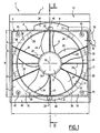
- la figure 1 est une vue schématique de face d'un dispositif de refroidissement conforme à l'invention ;
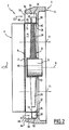
- la figure 2 est une vue en coupe selon II-II du dispositif de la figure 1 ; et
- la figure 3 est une vue schématique en perspective d'une hélice motorisée du dispositif de la figure 1.
- Tel que représenté sur les figures 1 et 2, le dispositif de refroidissement 2 comprend un échangeur de chaleur 4 (représenté uniquement par son contour en traits mixtes sur la figure 1) et un groupe moto-ventilateur 5, comportant une buse 6 de canalisation d'air, une hélice d'activation d'air 8, un moteur 9 d'entraînement de l'hélice 8, et un cadre 10 de support du groupe moto-ventilateur 5.
- Dans la suite de la description, les orientations utilisées sont les orientations usuelles des véhicules automobiles. Ainsi, les termes « avant », « arrière », « supérieur », et « inférieur » s'étendent par rapport à la direction et au sens d'avancement du véhicule automobile, schématisés par une flèche S sur la figure 2.
- L'échangeur 4 présente un contour sensiblement rectangulaire (figure 1), et est destiné à être traversé par un fluide à refroidir et par de l'air, en vue du refroidissement du fluide et du réchauffement de l'air.
- En se référant à la figure 1, la buse 6 comprend une ouverture avant rectangulaire 12, de contour sensiblement identique au contour de l'échangeur 4, et une ouverture arrière circulaire 14, les ouvertures 12, 14 s'étendant dans des plans sensiblement parallèles entre eux.
- L'ouverture 12 est plus grande que l'ouverture 14. Plus précisément, le diamètre de l'ouverture 14 est sensiblement égal à la hauteur h de l'ouverture 14, et inférieur à la largeur l de l'ouverture 14.
- La buse 6 comprend des parois internes 16 convergeant de l'ouverture 12 vers l'ouverture 14.
- La buse 6 comprend une platine centrale de support 18 s'étendant sensiblement dans le plan de l'ouverture 12, et fixée aux parois 16 par l'intermédiaire d'entretoises radiales 20 s'étendant entre la platine 18 et les parois 16. La platine 18 et les entretoises 20 forment une structure ajourée permettant le passage d'air à travers l'ouverture 12.
- En se référant à la figure 3, l'hélice 8 présente un axe de rotation R, et comprend un moyeu central 22, des pales d'activation d'air 24, par exemple au nombre de cinq et angulairement régulièrement espacées, s'étendant radialement vers l'extérieur à partir du moyeu 22, et une couronne 26 reliant les extrémités radiales extérieures des pales 24.
- Les pâles 24 constituent une région centrale principale d'activation d'air, et sont vrillées pour forcer une circulation d'un flux d'air principal axialement selon l'axe R.
- L'hélice 8 comprend des ailettes d'activation d'air 28 s'étendant radialement vers l'extérieur à partir de la couronne 26. Les ailettes 28 sont par exemple au nombre de dix, et angulairement régulièrement réparties sur la circonférence de la couronne 26.
- Les ailettes 28 constituent une région périphérique auxiliaire d'activation d'air, et sont profilées de façon à provoquer la circulation d'un flux d'air auxiliaire s'écoulant selon l'axe R, et dans le même sens que le flux d'air principal.
- A cet effet, chaque ailette 28 est inclinée par rapport à l'axe R de façon à imprimer à l'air un mouvement selon l'axe R.
- Plus précisément, chaque ailette 28 s'étend entre un bord avant d'attaque 28a et un bord arrière de fuite 28b, de façon que la tangente à chaque ailette 28 dans un plan perpendiculaire à une direction radiale de l'hélice 8 et passant par l'ailette 28, fait sensiblement en tout point de l'ailette 28 un angle non nul avec l'axe R.
- L'hélice 8 est avantageusement réalisée d'un seul tenant, par exemple par moulage par injection de matière plastique.
- Dans le mode de réalisation représenté, chaque ailette 28 présente, entre ses bords 28a et 28b une épaisseur sensiblement constante, et est courbe, avec une courbure orientée axialement vers l'arrière, pour améliorer l'écoulement de l'air. L'angle de la tangente à chaque ailette 28 par rapport à l'axe R, tel que défini ci-dessus, est donc variable, et décroît du bord 28a vers le bord 28b, par exemple d'un angle θ1 de sensiblement 60° à un angle θ2 de sensiblement 30°.
- En se référant à la figure 2, l'hélice 8 a son moyeu 22 monté à rotation sur le moteur 9, lui-même fixé sur une face arrière de la platine 18.
- L'hélice 8 est située en arrière de la buse 6, en travers de l'ouverture 14. La couronne 26 présente un diamètre sensiblement égal à celui de l'ouverture 14, de sorte que les pales 24 de l'hélice 8 sont situées en regard de l'ouverture 14, et que les ailettes 28 se situent radialement en dehors de l'ouverture 14.
- La buse 6 et l'hélice 8 sont montées sur le cadre 10, en regard d'une ouverture circulaire 32 de celui-ci, de même diamètre que l'ouverture 12 et la couronne 26.
- Plus précisément, le cadre 10 comprend un trou cylindrique 34 coaxial à l'ouverture 32 et possédant une paroi périphérique cylindrique 36, et une cloison annulaire 38 s'étendant radialement vers l'intérieur à partir de la paroi 36, un bord intérieur libre 40 de la cloison 38 délimitant l'ouverture 32.
- La paroi périphérique 36 présente un diamètre sensiblement égale au diamètre extérieur des ailettes 28, tout en étant légèrement supérieur.
- Des dégagements 42 (figure 1) sont ménagés dans une face avant 44 du cadre 10 à la périphérie du trou 34. Les dégagements 42 délimitent un contour rectangulaire sensiblement de même dimension que l'ouverture 14.
- La buse et l'hélice 8 sont disposées dans le trou 34, en regard de l'ouverture 32.
- L'hélice 8 est reçue dans le trou 34, la couronne 26 étant alignée avec le bord 40, de façon que les pales 14 se situent en regard de l'ouverture 32, et les ailettes 28 se situent en regard de la cloison 38.
- La buse 6 est reçue en partie dans le trou 34, devant l'hélice 8, et en partie dans les dégagements 42. La buse 6 est fixées sur le cadre 10, par exemple à l'aide d'organes de fixation (non représentés) traversant des orifices 45 (figure 1) de la buse 6, et vissés dans le cadre 10.
- L'échangeur 4 est fixé devant la buse 6, en regard de l'ouverture 12.
- En vue suivant la direction X (figure 1), la buse 6 et l'échangeur 4 masquent le trou 34 et les ailettes 28, excepté dans un secteur supérieur A, et un secteur inférieur B, dans lesquelles les ailettes 28 et le trou 34 débordent de la périphérie de la buse 6 et de l'échangeur 4, du fait du diamètre extérieur de ailettes 28 supérieure à la hauteur h de la buse 6 et de l'échangeur 4.
- Les ailettes 28 débordent sur deux côtés opposés de la buse 6. En variante, les ailettes 28 débordent sur un seul côté, ou sur plus de deux côtés de la buse 6.
- Dans les secteurs A et B, le trou 34 débouche sur la face 44, à la périphérie de la buse 6 et de l'échangeur 4, par des entrées d'air respectivement 46, 48, délimitées entre la surface externe de la buse 6 et la paroi 36.
- Le secteur A du trou 34 est un secteur de diamètre supérieur à celui du reste du trou 34, de façon que l'entrée 46 présente une aire supérieure à celle de l'entrée 48.
- Le dispositif 2 comprend un conduit 50 possédant une entrée 52 débouchant dans le trou 34, dans le secteur A et à proximité de la cloison 38, et une ou plusieurs sorties (non représentées) débouchant à distance. Les sorties débouchent dans un espace à refroidir, par exemple dans un boîtier électronique ou dans des freins du véhicule automobile.
- En fonctionnement, l'hélice 8 est entraînée par le moteur 9 en rotation autour de son axe R.
- Les pales 14 aspirent un flux d'air principal à travers l'échangeur 4, comme illustré par les flèches F1.
- Ce flux d'air principal, traverse l'échangeur 4 en se réchauffant, et est canalisé en aval de l'échangeur 4 dans un passage d'air principal P1 délimité par la surface intérieure de la buse 6 et la surface intérieure de la couronne 28. Le flux d'air principal est évacué vers l'arrière de l'hélice 8.
- Un passage d'air auxiliaire P2 est délimité entre la surface extérieure de la buse 6, la surface extérieure de la couronne 28, la paroi 36, et la cloison 38. Le passage P2 est séparé du passage P1, notamment par la buse 6 et la couronne 28. Ainsi, de l'air chaud circulant dans le passage P1 ne s'écoule pas dans le passage P2, de façon à ne pas perturber le refroidissement de l'espace à refroidir.
- Le passage P2 comprend une portion annulaire 56 et deux portions axiales 58 s'étendant entre la portion annulaire 56 et les entrée 46, 48, au-dessus et au-dessous de la buse 6.
- Les ailettes 28 s'étendent dans la portion annulaire 56. Les ailettes 28 forcent un flux d'air auxiliaire s'écoulant axialement vers l'arrière. Ce faisant, les ailettes 28 captent un flux d'air par les entrées 46 et 48 et les portions axiales 58, comme illustré par les flèches F2. L'air capté par les ailettes 28 est plaqué par celles-ci contre la cloison 38 qui est accolée aux ailettes 28. Il en résulte une augmentation de la pression de l'air contre la cloison 38 et dans la portion annulaire 56. L'air sous pression circule dans la portion annulaire 58 et s'évacue par la conduite 50, débouchant dans la portion annulaire 58, jusqu'à l'espace à refroidir.
- Les ailettes 28 configurées de façon à forcer un flux d'air axial permettent d'améliorer le débit d'air dans le passage P2, ce qui augmente le refroidissement de l'espace à refroidir. Avantageusement, ces ailettes sont réalisées dans un matériau relativement souple, comme par exemple du caoutchouc pour minimiser les jeux et par voie de conséquence, réduire les fuites.
- La cloison 38, venue de matière avec le cadre 10 fixe, coopère avec la couronne 26 pour délimiter le passage P2 de façon suffisamment étanche.
- En variante, des échangeurs d'air supplémentaires sont disposés en aval de l'hélice, dans le flux d'air principal, de façon à utiliser le flux d'air principal comme source froide dans ces échangeurs supplémentaires.
Claims (10)
- Dispositif de refroidissement pour véhicule automobile, du type comprenant un échangeur de chaleur (4), et un groupe moto-ventilateur (5) comprenant une hélice (8) motorisée, disposée à rotation autour d'un axe (R), en regard de l'échangeur (4), et destinée à aspirer, lors du fonctionnement de l'hélice (8), de l'air à travers l'échangeur de chaleur (4), caractérisé en ce que l'hélice (8) comprend une région périphérique (28) débordant, dans au moins un secteur angulaire (A, B), de la périphérie de l'échangeur (4) pour capter de l'air en dehors de l'échangeur (4), le groupe moto-ventilateur (5) comprenant des éléments (6, 10, 26, 38, 50) de canalisation de l'air capté par la région périphérique (28), la région périphérique (28) étant profilée de façon à former un flux d'air (F2) s'écoulant principalement parallèlement à l'axe de rotation (R) de l'hélice (8).
- Dispositif de refroidissement selon la revendication 1, caractérisé en ce que les éléments de canalisation (6, 10, 26, 38, 50) délimitent un passage principal (P1) pour l'air aspiré à travers l'échangeur de chaleur (4), et un passage auxiliaire (P2) pour l'air capté par la région périphérique (28), les éléments de canalisation (6, 10, 26, 38, 50) comprenant une paroi (6, 26) de séparation des passages principal (P1) et auxiliaire (P2).
- Dispositif selon la revendication 2, caractérisé en ce que les éléments de canalisation d'air définissent une sortie (32) pour le passage principal (P1) et une sortie (50) pour le passage auxiliaire (P2) séparées.
- Dispositif selon la revendication 2 ou 3, caractérisé en ce que la région périphérique (28) s'étend dans le passage auxiliaire (P2), une région centrale (14) de l'hélice (8) s'étendant dans le passage principal (P1), l'hélice (8) comprenant une couronne (26) délimitant la région centrale (14) et la région périphérique (28), la couronne (26) séparant les passages principal (P1) et auxiliaire (P2).
- Dispositif de refroidissement la revendication 4, caractérisé en ce que les éléments de canalisation (6, 10, 26, 38, 50) comprennent une buse (6) délimitant intérieurement le passage principal (P2), et un cadre (10) entourant la buse (6) et délimitant le passage auxiliaire (P2) avec une surface externe de la buse (6).
- Dispositif de refroidissement l'une quelconque des revendications 2 à 5, caractérisé en ce que les éléments de canalisation (6, 10, 26, 38, 50) comprennent une paroi (38) fixe sensiblement perpendiculaire à l'axe de rotation (R) de l'hélice (8), la paroi (38) délimitant le passage auxiliaire (P2), et étant accolée à la région périphérique (28), en aval dans le sens d'écoulement du flux d'air formé par la région périphérique (28) de l'hélice (8).
- Dispositif de refroidissement selon l'une quelconque des revendications précédentes, caractérisé en ce que la région périphérique comprend des ailettes d'activation d'air (28), la tangente à chaque ailette (28) dans un plan perpendiculaire à une direction radiale de l'hélice passant par l'ailette 28, faisant sensiblement en tout point de l'ailette (28) un angle non nul avec l'axe de rotation (R) de l'hélice (8).
- Dispositif de refroidissement selon la revendication 7, caractérisé en ce que chaque ailette (28) est courbe, et l'angle entre la tangente à chaque ailette (28) dans un plan perpendiculaire à une direction radiale de l'hélice et l'axe de rotation (R) est décroissant d'un bord d'attaque (28a) de l'ailette (28) vers un bord de fuite (28b) de l'ailette (28).
- Groupe moto-ventiliateur pour un dispositif de refroidissement selon l'une quelconque des revendications précédentes, comprenant les éléments de canalisation d'air (6, 10, 26, 38, 50), et l'hélice motorisée (8).
- Véhicule automobile comprenant un dispositif de refroidissement selon l'une quelconque des revendications 1 à 8.
Applications Claiming Priority (1)
| Application Number | Priority Date | Filing Date | Title |
|---|---|---|---|
| FR0505564A FR2886672B1 (fr) | 2005-06-01 | 2005-06-01 | Dispositif de refroidissement pour vehicule automobile, groupe moto-ventilateur pour un tel dispositif, et vehicule automobile correspondant |
Publications (2)
| Publication Number | Publication Date |
|---|---|
| EP1728987A1 true EP1728987A1 (fr) | 2006-12-06 |
| EP1728987B1 EP1728987B1 (fr) | 2011-04-27 |
Family
ID=35976504
Family Applications (1)
| Application Number | Title | Priority Date | Filing Date |
|---|---|---|---|
| EP20060300540 Expired - Lifetime EP1728987B1 (fr) | 2005-06-01 | 2006-05-31 | Dispositif de refroidissement pour un véhicule automobile et le véhicule automobile correspondant |
Country Status (4)
| Country | Link |
|---|---|
| EP (1) | EP1728987B1 (fr) |
| AT (1) | ATE507377T1 (fr) |
| DE (1) | DE602006021508D1 (fr) |
| FR (1) | FR2886672B1 (fr) |
Citations (3)
| Publication number | Priority date | Publication date | Assignee | Title |
|---|---|---|---|---|
| FR2269636A1 (en) * | 1974-04-18 | 1975-11-28 | Saviem | Cooling system for supercharged diesel engine - uses air drawn through radiator to cool air from supercharger |
| DE4136282C1 (fr) * | 1991-11-04 | 1993-05-06 | Adam Opel Ag, 6090 Ruesselsheim, De | |
| US5269264A (en) * | 1991-08-30 | 1993-12-14 | Weinhold Wolfgang P | Engine ventilation in an automotive vehicle |
-
2005
- 2005-06-01 FR FR0505564A patent/FR2886672B1/fr not_active Expired - Fee Related
-
2006
- 2006-05-31 AT AT06300540T patent/ATE507377T1/de not_active IP Right Cessation
- 2006-05-31 DE DE200660021508 patent/DE602006021508D1/de not_active Expired - Lifetime
- 2006-05-31 EP EP20060300540 patent/EP1728987B1/fr not_active Expired - Lifetime
Patent Citations (3)
| Publication number | Priority date | Publication date | Assignee | Title |
|---|---|---|---|---|
| FR2269636A1 (en) * | 1974-04-18 | 1975-11-28 | Saviem | Cooling system for supercharged diesel engine - uses air drawn through radiator to cool air from supercharger |
| US5269264A (en) * | 1991-08-30 | 1993-12-14 | Weinhold Wolfgang P | Engine ventilation in an automotive vehicle |
| DE4136282C1 (fr) * | 1991-11-04 | 1993-05-06 | Adam Opel Ag, 6090 Ruesselsheim, De |
Also Published As
| Publication number | Publication date |
|---|---|
| EP1728987B1 (fr) | 2011-04-27 |
| FR2886672B1 (fr) | 2007-09-21 |
| DE602006021508D1 (de) | 2011-06-09 |
| ATE507377T1 (de) | 2011-05-15 |
| FR2886672A1 (fr) | 2006-12-08 |
Similar Documents
| Publication | Publication Date | Title |
|---|---|---|
| EP3857149B1 (fr) | Module d'échange thermique de véhicule automobile | |
| FR3045741A1 (fr) | Pulseur d'aspiration destine a un dispositif de chauffage, ventilation et/ou climatisation d'un vehicule automobile et dispositif de chauffage, ventilation et/ou climatisation | |
| FR2917714A1 (fr) | Turboreacteur pour aeronef | |
| FR3093760A1 (fr) | Module de refroidissement pour véhicule automobile électrique à turbomachine tangentielle | |
| EP1728987B1 (fr) | Dispositif de refroidissement pour un véhicule automobile et le véhicule automobile correspondant | |
| EP3853057A1 (fr) | Module d'echange thermique pour vehicule automobile | |
| EP2154013B1 (fr) | Appareil de chauffage, ventilation et/ou climatisation à acoustique améliorée | |
| EP4204669B1 (fr) | Module de refroidissement pour véhicule automobile électrique à turbomachine tangentielle | |
| FR3115731A1 (fr) | Module de refroidissement pour véhicule automobile électrique ou hybride à turbomachine tangentielle | |
| FR2920044A1 (fr) | Boitier constitutif d'une installation de ventilation, de chauffage et/ou de climatisation pourvu de moyens d'attenuation acoustique d'ondes sonores et installation comprenant un tel boitier | |
| FR3074236A1 (fr) | Groupe moto-ventilateur pour vehicule automobile | |
| FR3115735A1 (fr) | Module de refroidissement pour véhicule automobile électrique ou hybride à turbomachine tangentielle | |
| FR3069896A1 (fr) | Roue de type centrifuge pour groupe moto-ventilateur | |
| EP3061634B1 (fr) | Dispositif de chauffage, ventilation et/ou climatisation pour véhicule automobile | |
| FR3082883A1 (fr) | Dispositif de ventilation pour vehicule automobile | |
| FR3073563A1 (fr) | Dispositif de ventilation pour vehicule automobile | |
| FR3095162A1 (fr) | Groupe moto-ventilateur d’un pulseur d’air d’un véhicule automobile | |
| FR2769264A1 (fr) | Dispositif de chauffage-climatisation pour vehicule automobile, avec groupe moto-ventilateur a filtre a air extractible integre | |
| FR3069895A1 (fr) | Roue de type centrifuge pour groupe moto-ventilateur | |
| FR3133661A1 (fr) | Groupe motorisé de ventilation | |
| FR3154347A1 (fr) | Boîtier et dispositif de chauffage, ventilation et/ou conditionnement d’air, notamment pour véhicule automobile | |
| FR3074237A1 (fr) | Groupe moto-ventilateur pour vehicule automobile | |
| WO2016131679A1 (fr) | Installation de conditionnement thermique d'un habitacle de vehicule automobile | |
| EP3938232A1 (fr) | Module de refroidissement pour véhicule automobile | |
| FR3066581A1 (fr) | Pulseur d'aspiration destine a un dispositif de chauffage, ventilation et/ou climatisation d'un vehicule automobile et dispositif de chauffage, ventilation et/ou climatisation |
Legal Events
| Date | Code | Title | Description |
|---|---|---|---|
| PUAI | Public reference made under article 153(3) epc to a published international application that has entered the european phase |
Free format text: ORIGINAL CODE: 0009012 |
|
| AK | Designated contracting states |
Kind code of ref document: A1 Designated state(s): AT BE BG CH CY CZ DE DK EE ES FI FR GB GR HU IE IS IT LI LT LU LV MC NL PL PT RO SE SI SK TR |
|
| AX | Request for extension of the european patent |
Extension state: AL BA HR MK YU |
|
| 17P | Request for examination filed |
Effective date: 20070504 |
|
| 17Q | First examination report despatched |
Effective date: 20070601 |
|
| AKX | Designation fees paid |
Designated state(s): AT BE BG CH CY CZ DE DK EE ES FI FR GB GR HU IE IS IT LI LT LU LV MC NL PL PT RO SE SI SK TR |
|
| RTI1 | Title (correction) |
Free format text: COOLING DEVICE FOR A VEHICLE AND THE ASSOCIATED VEHICLE |
|
| GRAP | Despatch of communication of intention to grant a patent |
Free format text: ORIGINAL CODE: EPIDOSNIGR1 |
|
| GRAS | Grant fee paid |
Free format text: ORIGINAL CODE: EPIDOSNIGR3 |
|
| GRAA | (expected) grant |
Free format text: ORIGINAL CODE: 0009210 |
|
| AK | Designated contracting states |
Kind code of ref document: B1 Designated state(s): AT BE BG CH CY CZ DE DK EE ES FI FR GB GR HU IE IS IT LI LT LU LV MC NL PL PT RO SE SI SK TR |
|
| REG | Reference to a national code |
Ref country code: GB Ref legal event code: FG4D Free format text: NOT ENGLISH |
|
| REG | Reference to a national code |
Ref country code: CH Ref legal event code: EP |
|
| REG | Reference to a national code |
Ref country code: IE Ref legal event code: FG4D Free format text: LANGUAGE OF EP DOCUMENT: FRENCH |
|
| REF | Corresponds to: |
Ref document number: 602006021508 Country of ref document: DE Date of ref document: 20110609 Kind code of ref document: P |
|
| REG | Reference to a national code |
Ref country code: DE Ref legal event code: R096 Ref document number: 602006021508 Country of ref document: DE Effective date: 20110609 |
|
| REG | Reference to a national code |
Ref country code: NL Ref legal event code: VDEP Effective date: 20110427 |
|
| REG | Reference to a national code |
Ref country code: GB Ref legal event code: 746 Effective date: 20110801 |
|
| LTIE | Lt: invalidation of european patent or patent extension |
Effective date: 20110427 |
|
| REG | Reference to a national code |
Ref country code: DE Ref legal event code: R084 Ref document number: 602006021508 Country of ref document: DE Effective date: 20110725 |
|
| PG25 | Lapsed in a contracting state [announced via postgrant information from national office to epo] |
Ref country code: PT Free format text: LAPSE BECAUSE OF FAILURE TO SUBMIT A TRANSLATION OF THE DESCRIPTION OR TO PAY THE FEE WITHIN THE PRESCRIBED TIME-LIMIT Effective date: 20110829 Ref country code: SE Free format text: LAPSE BECAUSE OF FAILURE TO SUBMIT A TRANSLATION OF THE DESCRIPTION OR TO PAY THE FEE WITHIN THE PRESCRIBED TIME-LIMIT Effective date: 20110427 Ref country code: LT Free format text: LAPSE BECAUSE OF FAILURE TO SUBMIT A TRANSLATION OF THE DESCRIPTION OR TO PAY THE FEE WITHIN THE PRESCRIBED TIME-LIMIT Effective date: 20110427 |
|
| REG | Reference to a national code |
Ref country code: IE Ref legal event code: FD4D |
|
| BERE | Be: lapsed |
Owner name: PEUGEOT CITROEN AUTOMOBILES SA Effective date: 20110531 |
|
| PG25 | Lapsed in a contracting state [announced via postgrant information from national office to epo] |
Ref country code: SI Free format text: LAPSE BECAUSE OF FAILURE TO SUBMIT A TRANSLATION OF THE DESCRIPTION OR TO PAY THE FEE WITHIN THE PRESCRIBED TIME-LIMIT Effective date: 20110427 Ref country code: GR Free format text: LAPSE BECAUSE OF FAILURE TO SUBMIT A TRANSLATION OF THE DESCRIPTION OR TO PAY THE FEE WITHIN THE PRESCRIBED TIME-LIMIT Effective date: 20110728 Ref country code: FI Free format text: LAPSE BECAUSE OF FAILURE TO SUBMIT A TRANSLATION OF THE DESCRIPTION OR TO PAY THE FEE WITHIN THE PRESCRIBED TIME-LIMIT Effective date: 20110427 Ref country code: ES Free format text: LAPSE BECAUSE OF FAILURE TO SUBMIT A TRANSLATION OF THE DESCRIPTION OR TO PAY THE FEE WITHIN THE PRESCRIBED TIME-LIMIT Effective date: 20110807 Ref country code: AT Free format text: LAPSE BECAUSE OF FAILURE TO SUBMIT A TRANSLATION OF THE DESCRIPTION OR TO PAY THE FEE WITHIN THE PRESCRIBED TIME-LIMIT Effective date: 20110427 Ref country code: CY Free format text: LAPSE BECAUSE OF FAILURE TO SUBMIT A TRANSLATION OF THE DESCRIPTION OR TO PAY THE FEE WITHIN THE PRESCRIBED TIME-LIMIT Effective date: 20110427 Ref country code: IS Free format text: LAPSE BECAUSE OF FAILURE TO SUBMIT A TRANSLATION OF THE DESCRIPTION OR TO PAY THE FEE WITHIN THE PRESCRIBED TIME-LIMIT Effective date: 20110827 Ref country code: LV Free format text: LAPSE BECAUSE OF FAILURE TO SUBMIT A TRANSLATION OF THE DESCRIPTION OR TO PAY THE FEE WITHIN THE PRESCRIBED TIME-LIMIT Effective date: 20110427 |
|
| PG25 | Lapsed in a contracting state [announced via postgrant information from national office to epo] |
Ref country code: MC Free format text: LAPSE BECAUSE OF NON-PAYMENT OF DUE FEES Effective date: 20110531 Ref country code: NL Free format text: LAPSE BECAUSE OF FAILURE TO SUBMIT A TRANSLATION OF THE DESCRIPTION OR TO PAY THE FEE WITHIN THE PRESCRIBED TIME-LIMIT Effective date: 20110427 |
|
| REG | Reference to a national code |
Ref country code: CH Ref legal event code: PL |
|
| PG25 | Lapsed in a contracting state [announced via postgrant information from national office to epo] |
Ref country code: CZ Free format text: LAPSE BECAUSE OF FAILURE TO SUBMIT A TRANSLATION OF THE DESCRIPTION OR TO PAY THE FEE WITHIN THE PRESCRIBED TIME-LIMIT Effective date: 20110427 Ref country code: CH Free format text: LAPSE BECAUSE OF NON-PAYMENT OF DUE FEES Effective date: 20110531 Ref country code: IE Free format text: LAPSE BECAUSE OF FAILURE TO SUBMIT A TRANSLATION OF THE DESCRIPTION OR TO PAY THE FEE WITHIN THE PRESCRIBED TIME-LIMIT Effective date: 20110427 Ref country code: EE Free format text: LAPSE BECAUSE OF FAILURE TO SUBMIT A TRANSLATION OF THE DESCRIPTION OR TO PAY THE FEE WITHIN THE PRESCRIBED TIME-LIMIT Effective date: 20110427 Ref country code: LI Free format text: LAPSE BECAUSE OF NON-PAYMENT OF DUE FEES Effective date: 20110531 |
|
| PG25 | Lapsed in a contracting state [announced via postgrant information from national office to epo] |
Ref country code: RO Free format text: LAPSE BECAUSE OF FAILURE TO SUBMIT A TRANSLATION OF THE DESCRIPTION OR TO PAY THE FEE WITHIN THE PRESCRIBED TIME-LIMIT Effective date: 20110427 Ref country code: DK Free format text: LAPSE BECAUSE OF FAILURE TO SUBMIT A TRANSLATION OF THE DESCRIPTION OR TO PAY THE FEE WITHIN THE PRESCRIBED TIME-LIMIT Effective date: 20110427 Ref country code: PL Free format text: LAPSE BECAUSE OF FAILURE TO SUBMIT A TRANSLATION OF THE DESCRIPTION OR TO PAY THE FEE WITHIN THE PRESCRIBED TIME-LIMIT Effective date: 20110427 Ref country code: SK Free format text: LAPSE BECAUSE OF FAILURE TO SUBMIT A TRANSLATION OF THE DESCRIPTION OR TO PAY THE FEE WITHIN THE PRESCRIBED TIME-LIMIT Effective date: 20110427 |
|
| PLBE | No opposition filed within time limit |
Free format text: ORIGINAL CODE: 0009261 |
|
| STAA | Information on the status of an ep patent application or granted ep patent |
Free format text: STATUS: NO OPPOSITION FILED WITHIN TIME LIMIT |
|
| PG25 | Lapsed in a contracting state [announced via postgrant information from national office to epo] |
Ref country code: BE Free format text: LAPSE BECAUSE OF NON-PAYMENT OF DUE FEES Effective date: 20110531 |
|
| 26N | No opposition filed |
Effective date: 20120130 |
|
| REG | Reference to a national code |
Ref country code: DE Ref legal event code: R097 Ref document number: 602006021508 Country of ref document: DE Effective date: 20120130 |
|
| PG25 | Lapsed in a contracting state [announced via postgrant information from national office to epo] |
Ref country code: IT Free format text: LAPSE BECAUSE OF FAILURE TO SUBMIT A TRANSLATION OF THE DESCRIPTION OR TO PAY THE FEE WITHIN THE PRESCRIBED TIME-LIMIT Effective date: 20110427 |
|
| PGFP | Annual fee paid to national office [announced via postgrant information from national office to epo] |
Ref country code: DE Payment date: 20120423 Year of fee payment: 7 |
|
| PGFP | Annual fee paid to national office [announced via postgrant information from national office to epo] |
Ref country code: GB Payment date: 20120423 Year of fee payment: 7 Ref country code: FR Payment date: 20120625 Year of fee payment: 7 |
|
| PG25 | Lapsed in a contracting state [announced via postgrant information from national office to epo] |
Ref country code: LU Free format text: LAPSE BECAUSE OF NON-PAYMENT OF DUE FEES Effective date: 20110531 |
|
| PG25 | Lapsed in a contracting state [announced via postgrant information from national office to epo] |
Ref country code: BG Free format text: LAPSE BECAUSE OF FAILURE TO SUBMIT A TRANSLATION OF THE DESCRIPTION OR TO PAY THE FEE WITHIN THE PRESCRIBED TIME-LIMIT Effective date: 20110727 |
|
| PG25 | Lapsed in a contracting state [announced via postgrant information from national office to epo] |
Ref country code: TR Free format text: LAPSE BECAUSE OF FAILURE TO SUBMIT A TRANSLATION OF THE DESCRIPTION OR TO PAY THE FEE WITHIN THE PRESCRIBED TIME-LIMIT Effective date: 20110427 |
|
| PG25 | Lapsed in a contracting state [announced via postgrant information from national office to epo] |
Ref country code: HU Free format text: LAPSE BECAUSE OF FAILURE TO SUBMIT A TRANSLATION OF THE DESCRIPTION OR TO PAY THE FEE WITHIN THE PRESCRIBED TIME-LIMIT Effective date: 20110427 |
|
| GBPC | Gb: european patent ceased through non-payment of renewal fee |
Effective date: 20130531 |
|
| PG25 | Lapsed in a contracting state [announced via postgrant information from national office to epo] |
Ref country code: DE Free format text: LAPSE BECAUSE OF NON-PAYMENT OF DUE FEES Effective date: 20131203 |
|
| REG | Reference to a national code |
Ref country code: FR Ref legal event code: ST Effective date: 20140131 |
|
| REG | Reference to a national code |
Ref country code: DE Ref legal event code: R119 Ref document number: 602006021508 Country of ref document: DE Effective date: 20131203 |
|
| PG25 | Lapsed in a contracting state [announced via postgrant information from national office to epo] |
Ref country code: GB Free format text: LAPSE BECAUSE OF NON-PAYMENT OF DUE FEES Effective date: 20130531 |
|
| PG25 | Lapsed in a contracting state [announced via postgrant information from national office to epo] |
Ref country code: FR Free format text: LAPSE BECAUSE OF NON-PAYMENT OF DUE FEES Effective date: 20130531 |