EP1728357B1 - System und verfahren zur qualitätsstatusanalyse eines zugangsnetzes, das breitband-telekommunikationsdienste unterstützt - Google Patents
System und verfahren zur qualitätsstatusanalyse eines zugangsnetzes, das breitband-telekommunikationsdienste unterstützt Download PDFInfo
- Publication number
- EP1728357B1 EP1728357B1 EP04722603A EP04722603A EP1728357B1 EP 1728357 B1 EP1728357 B1 EP 1728357B1 EP 04722603 A EP04722603 A EP 04722603A EP 04722603 A EP04722603 A EP 04722603A EP 1728357 B1 EP1728357 B1 EP 1728357B1
- Authority
- EP
- European Patent Office
- Prior art keywords
- network
- data sources
- transmissive
- broadband
- analysis system
- Prior art date
- Legal status (The legal status is an assumption and is not a legal conclusion. Google has not performed a legal analysis and makes no representation as to the accuracy of the status listed.)
- Expired - Lifetime
Links
- 238000004458 analytical method Methods 0.000 title claims abstract description 54
- 238000000034 method Methods 0.000 title claims abstract description 28
- 230000003068 static effect Effects 0.000 claims abstract description 18
- 230000005540 biological transmission Effects 0.000 claims abstract description 15
- 230000010365 information processing Effects 0.000 claims abstract description 9
- 238000004891 communication Methods 0.000 claims description 19
- 230000003044 adaptive effect Effects 0.000 claims description 8
- 238000012545 processing Methods 0.000 claims description 8
- 238000005259 measurement Methods 0.000 abstract description 11
- 230000008569 process Effects 0.000 abstract description 7
- 238000007726 management method Methods 0.000 description 15
- 238000005516 engineering process Methods 0.000 description 12
- RYGMFSIKBFXOCR-UHFFFAOYSA-N Copper Chemical compound [Cu] RYGMFSIKBFXOCR-UHFFFAOYSA-N 0.000 description 7
- 229910052802 copper Inorganic materials 0.000 description 7
- 239000010949 copper Substances 0.000 description 7
- 238000012797 qualification Methods 0.000 description 6
- 230000000694 effects Effects 0.000 description 4
- 238000005070 sampling Methods 0.000 description 4
- 230000001419 dependent effect Effects 0.000 description 3
- 238000011161 development Methods 0.000 description 3
- 239000000523 sample Substances 0.000 description 3
- 238000004364 calculation method Methods 0.000 description 2
- 238000012937 correction Methods 0.000 description 2
- 230000000875 corresponding effect Effects 0.000 description 2
- 239000000835 fiber Substances 0.000 description 2
- 230000006870 function Effects 0.000 description 2
- 238000003780 insertion Methods 0.000 description 2
- 230000037431 insertion Effects 0.000 description 2
- 238000012544 monitoring process Methods 0.000 description 2
- 238000013439 planning Methods 0.000 description 2
- 230000009467 reduction Effects 0.000 description 2
- 238000012360 testing method Methods 0.000 description 2
- 238000012384 transportation and delivery Methods 0.000 description 2
- 238000011144 upstream manufacturing Methods 0.000 description 2
- 102000016917 Complement C1 Human genes 0.000 description 1
- 108010028774 Complement C1 Proteins 0.000 description 1
- 230000001276 controlling effect Effects 0.000 description 1
- 230000002596 correlated effect Effects 0.000 description 1
- 230000008878 coupling Effects 0.000 description 1
- 238000010168 coupling process Methods 0.000 description 1
- 238000005859 coupling reaction Methods 0.000 description 1
- 230000009977 dual effect Effects 0.000 description 1
- 230000002708 enhancing effect Effects 0.000 description 1
- 238000009434 installation Methods 0.000 description 1
- 238000009413 insulation Methods 0.000 description 1
- 230000003993 interaction Effects 0.000 description 1
- 230000002452 interceptive effect Effects 0.000 description 1
- 238000012986 modification Methods 0.000 description 1
- 230000004048 modification Effects 0.000 description 1
- 230000009257 reactivity Effects 0.000 description 1
- 230000000630 rising effect Effects 0.000 description 1
- 229920006395 saturated elastomer Polymers 0.000 description 1
- 238000012216 screening Methods 0.000 description 1
- 238000000638 solvent extraction Methods 0.000 description 1
- 238000001228 spectrum Methods 0.000 description 1
Images


Classifications
-
- H—ELECTRICITY
- H04—ELECTRIC COMMUNICATION TECHNIQUE
- H04M—TELEPHONIC COMMUNICATION
- H04M11/00—Telephonic communication systems specially adapted for combination with other electrical systems
- H04M11/06—Simultaneous speech and data transmission, e.g. telegraphic transmission over the same conductors
- H04M11/062—Simultaneous speech and data transmission, e.g. telegraphic transmission over the same conductors using different frequency bands for speech and other data
-
- H—ELECTRICITY
- H04—ELECTRIC COMMUNICATION TECHNIQUE
- H04L—TRANSMISSION OF DIGITAL INFORMATION, e.g. TELEGRAPHIC COMMUNICATION
- H04L41/00—Arrangements for maintenance, administration or management of data switching networks, e.g. of packet switching networks
- H04L41/50—Network service management, e.g. ensuring proper service fulfilment according to agreements
- H04L41/5003—Managing SLA; Interaction between SLA and QoS
- H04L41/5009—Determining service level performance parameters or violations of service level contracts, e.g. violations of agreed response time or mean time between failures [MTBF]
Definitions
- the present invention generally relates to the provision of high speed telecommunication services.
- the present invention relates to a system and a method for the quality status analysis of an access network of a fixed network supporting broadband telecommunication services.
- the present invention relates to a system and a method for the quality status analysis of a Copper Access Network supporting broadband services based on a xDSL technology ("generic Digital Subscriber Line").
- DSL Digital Subscriber Line
- HDSL High-bit-rate Digital Subscriber Line
- RDSL Random Access Digital Subscriber Line
- SDSL Symmetric Digital Subscriber Line
- VDSL Very High-speed Digital Subscriber Line
- a problem encountered in the provision of xDSL services is that subscriber loops have largely been neglected from a technology upgrade perspective.
- Existing subscriber loops and the structure of the copper distribution network were originally designed for narrow band voice telephony and not to support high speed data services. Consequently, the electrical characteristics of the cables and subscriber loops set limits to the provision of broadband services: for example, many subscriber loops include wire gauge changes and bridged taps (unused extension lines) which limit the available bandwidth, limiting the performance of the loops with respect to the delivery of an xDSL service.
- US 6,266,395 discloses a method and an apparatus for single-ended qualification of subscriber loops for xDSL services.
- the method involves first screening a subscriber loop database for disqualifying devices or services, associated with that loop, which are incompatible with xDSL services. If none are found, a set of predetermined electrical characteristics of the subscriber loop are derived from information in the database, or directly measured using test equipment at a central office end of the subscriber loop. The electrical characteristics are used to calculate an available bandwidth for xDSL services on the subscriber loop.
- WO 01/13609 teaches loop qualification methods and systems for qualifying an ADSL loop which involve evaluating Loop Make-Up (LMU) data to determine whether loops are qualified for certain services, such as ADSL services or other digital services.
- LMU data includes such information as whether the loop is comprised of copper, fibre, it is a DLC ("Digital Loop Carrier"), its length, resist zone, carrier zone, loading factor, the existence of a DAML ("Digital Added Main Line”) and taper code information.
- the loop qualification methods and systems obtain LMU data on existing loops as well as information on loops which have not yet been completed.
- Network service providers (NSP) interface with the loop qualification systems to determine whether certain lines are qualified for a service.
- Loop qualification systems also include web-based interfaces to allow both NSPs and end users to make an inquiry as to the capability of a given loop.
- the Applicant has observed that a network operator's ability to obtain a degree of knowledge that is punctual, updated and evolving over time of the potential of its own access network critically depends on the ability to integrate and mutually correlate information about the structure of the network, the number and type of systems installed thereon and the transmissive characteristics of the network itself. Whilst network structure and the number and type of installed systems are typically described in appropriate databases (Network Inventory) normally contained and updated within computerised databases, the transmissive characteristics of the network are generally not available locally but only on a statistical basis as the national or regional level.
- the transmissive characteristics of the copper network do not depend only on the physical characteristics (e.g. the electrical capacity) and topological characteristics (e.g. the length) of the single subscriber loop, but also on the degree of electromagnetic coupling between the loop and the surrounding environment.
- the actual transmissive capacity available on the loop supporting the xDSL services is also limited by the other transmissive systems (homologous or "legacy", for instance HDB3 or ISDN-BA) operating on the loops present in the same cable sector, whose transmitted signals, by proximity effect, are coupled by crosstalk on the loop in question, constitute a significant interference to the transmission.
- the Applicant faced the problem of providing a network operator with a measurement that is punctual, updated and evolving over time of the quality status of its access network without requiring the installation of specific measuring tools at the central office of the access network itself.
- the Applicant has observed that, providing a system and a method for the quality status analysis of an access network of a fixed network supporting broadband telecommunication services which acquires network information both from the services that are already installed and active on the network and from the network inventory, a network operator can be provided with punctual indexes of the quality status of its access network.
- the Applicant has observed that the problem described above can be solved by a system and related method for the quality status analysis of an access network of a fixed network infrastructure supporting broadband telecommunication services comprising an information acquisition module configured for drawing static network information stored in network inventories and dynamic network information linked to measurements made during transmission on the broadband systems already installed and active in the network.
- the system further comprises an information processing module configured for collecting said static and dynamic network information and processing them to obtain at least an index representative of the quality status of the access network.
- a system for the quality status analysis of an access network of a fixed network infrastructure said access network comprises a plurality of cables, a set thereof supporting broadband transmissive systems, comprises:
- Another aspect of the present invention relates to a method for the quality status analysis of an access network of a fixed network infrastructure, said access network comprising a plurality of cables, a set thereof supporting broadband transmissive systems, said method comprising the steps of:
- a further aspect of the present invention relates to a computer product able to be loaded into the memory of at least an electronic computer and comprising portions of software code to implement the method according to the invention when the product is executed on a computer: in this context, said term must be considered wholly equivalent to the mention of a computer readable means comprising instructions for controlling a computer network to implement a method according to the invention.
- Reference to "at least an electronic computer” is destined to highlight the possibility of implementing the solution according to the invention in a decentralised context.
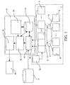
- the analysis system operates on a fixed network infrastructure 1 comprising: an access network 2, network apparatuses 3 (e.g. central office or cabinets, remote with respect to the central office) and user equipment 4 (for example, electronic computers provided with transceivers xDSL, telephones, gateway etc.).
- the fixed network infrastructure 1 can also comprise a plurality of management modules 3a ("Element Manager"), each one including a program to configure and control multiple network apparatuses 3 associated thereto. The presence or absence of the management modules 3a depends on the specific network apparatus 3.
- the access network 2 for example made of copper, includes a plurality of cables 6 to connect the user equipment 4 to the network apparatuses 3.
- Each cable 6 comprises a primary link 6a including a plurality of subscriber loops ("pairs") 7 (see Figure 2 ), a set thereof supporting broadband transmissive systems, for example of the xDSL type.
- Broadband transmissive systems imply a high speed data transmission between the network apparatuses 3 and the user equipment 4.
- each network apparatus 3 can for example include a central office 8, comprising a Main Distribution Frame 9 (MDF) into which converge the subscriber loops 7, connected to that central office, and multiplexers 10, so-called DSLAMs ("Digital Subscriber Line Access Multiplexer”), mutually connected through the Main Distribution Frame 9 and configured for managing the data/voice traffic coming from the subscriber loops 7.
- MDF Main Distribution Frame 9
- DSLAMs Digital Subscriber Line Access Multiplexer
- each cable 6 can also comprise secondary links 6b connecting branching and flexibility points provided for example by cabinets 11 and by boxes 12. To each cabinet 11 can be connected multiple boxes 12. To each box 12 can then be connected multiple user equipment items 4 whereto are associated different types of xDSL or voice services.
- network inventories 5 in which is stored static network information comprising, for example:
- the analysis system of the invention designated by the number 13, comprises an information acquisition module 14, an information processing module 15, an interface module 16 with a network operator 40, a network and transmissive systems model 30 and a database 17.
- the information acquisition module 14 is configured for collecting network information both from the broadband transmissive systems that are already installed and active in the network and from the network inventories 5.
- the information acquisition module 14, through a remote access to the network apparatuses 3, can collect dynamic network information linked to measurements taken during transmission on the broadband systems that are already installed and active in the network. Access to the network apparatuses 3 can occur directly or, if present, through the management modules 3a.
- This dynamic information comprises transmissive parameters which can for example include:
- the information acquisition module 14 for remote access to the network apparatuses 3 comprises a data access portion 18, schematically shown in Figures 3 , 4 and 5 .
- each “task” 19 is a programmed sequence, independent from the others, of measurement commands to be sent to the network apparatuses 3 to acquire the transmissive parameters of interest.
- Each “task” 19 can for example comprise:
- each "task" 19 is subdivided into one or more sessions 20, which are performed in parallel for a more efficient and flexible use of the resources.
- Each session 20 contains blocks of measurement request commands 21 to be sent to network apparatuses 3 serving a specific geographic area.
- a session 20 can be subdivided into a first and second sub-session 20a, 20b: the first sub-session 20a containing blocks of commands 21a to be sent to network apparatuses 3 positioned in a first geographic area A (for example, the network apparatuses 3 serving the North Milan area); the second sub-session 20b containing blocks of commands 21b to be sent to network apparatuses 3 positioned in a second geographic area B (for example, the network apparatuses 3 serving the South Milan area).
- first geographic area A for example, the network apparatuses 3 serving the North Milan area
- the second sub-session 20b containing blocks of commands 21b to be sent to network apparatuses 3 positioned in a second geographic area B (for example, the network apparatuses 3 serving the South Milan area).
- a further session 20 can be subdivided into a first and second sub-session 20c, 20d: the first sub-session 20c containing blocks of commands 21c to be sent to network apparatuses 3 positioned in a third geographic area C (for example the network apparatuses 3 serving the East Milan area); the second sub-session 20d containing blocks of commands 21d to be sent to network apparatuses 3 positioned in a fourth geographic area D (for example the network apparatuses 3 serving the West Milan area).
- each blocks of commands 21 relates to a single network apparatus 3 and multiple blocks of commands 21 can relate to a same network apparatus 3.
- the related session 20 queries an adaptive controller 50 which determines to which network apparatus 3 the specific blocks of commands 21 must be sent, through a communication bus 22 and with which priority.
- each block of commands 21 is sent to the related network apparatus 3 through a handler 23.
- Each handler 23 is a software process handling communication with the network apparatus 3 or the management module 3a associated thereto, through one or more communication channels 24 ⁇ e.g. TCP connections).
- handlers 23 communicating with the network apparatuses 3 positioned in a specific geographic area can be joined in a single group ("handler group").
- the adaptive controller 50 comprises a complete list of the handler 23 with associated information about:
- Each session 20 queries the adaptive controller 50 using some parameters, such as:
- the adaptive controller 50 monitors:
- handlers 23 can be provided:
- each apparatus handler 23a/element manager handler 23b is configured for managing:
- the apparatus handler 23a comprises:
- the element manager handler 23b comprises:
- the measurements obtained through queries on network apparatuses 3/management modules 3a are then stored in an appropriate database, not shown in the figures, which can be included or external to the analysis system 13.
- the data access portion 18 thanks to a double access level (directed to the network apparatuses 3 or through the management modules 3a) combined with the management in blocks (of configurable dimensions) of the commands, allows an optimal calibration between:
- Both the handlers 23 and the adaptive controller 50 can implement rules/policies for the performance of their task.
- Said rules/policies generally take the form of mathematical formulas which, based on the input parameters associated to each block of commands 21 considered, provided a single value of priority related to the block of commands 21. For example, the block of commands 21 with the highest priority of value can be selected.
- a simple example of these formulas is a linear expression in which the precedence value is given by the sum of the input parameters weighted with appropriate multiplication factors.
- the information acquisition module 14 is also provided with an interface, for instance of the FTP type, for accessing the network inventories 5 in order to periodically acquire the static network information contained therein, for example the configuration of each broadband transmissive system installed and active in the network, inclusive of a customer ID.
- the information acquisition module 14 can be provided with an additional interface towards commercial databases and/or other databases available to the network operator where are available the addresses of the user equipment 4 whereto the broadband services are associated.
- the information processing module 15 is configured for obtaining from the processing of the network information acquired by the information acquisition module 14, a first and a second index I sg , I st , representing the quality status of the access network 2, and in particular its degree of saturation. These two indexes are respectively the geometric saturation index I sg and the transmissive saturation index I st .
- the geometric saturation index I sg is indicative of the degree of use of the cables in terms of broadband transmissive systems supported by the cables.
- the geometric saturation index I sg is a positive number, assumed to vary between 0 and 1. It is equal to one if the degree of use of the cables, in a determined network portion, reaches 100% in terms of pairs used in broadband transmission.
- the transmissive saturation index T st is indicative of the transmissive status of the cables in terms of bit rate of the broadband transmissive systems supported by the cables.
- the transmissive saturation index I st is a positive number, assumed to vary between 0 and 1. It is equal to one if all broadband transmissive systems operating on the pairs present in a determined network portion reach the maximum possible bit rate.
- Said indexes can be calculated for the entire access network 2, as well as for a specific portion thereof (for example, the one serving a metropolitan area), for a specific cable area ("Local Exchange”) and for a single subscriber loop.
- M ⁇ ⁇ m i ⁇ N
- I sg M N ⁇ 1 the complement 1 - M/N relates to the cable portion not currently involved by the presence of broadband transmissive systems and in which it can be assumed that new broadband transmissive systems will be installed in the future, according to the commercial development plans set by the network operator.
- the transmissive saturation index I st can be assessed starting from the transmissive parameters measured by the information acquisition module 14, on the broadband transmissive systems already installed and active in the network portion in question.
- a methodology for assessing the transmissive saturation index I st is based, in the case of ADSL transmissive systems, on the direct measurement (through the data access portion 18) of the current bit rate (CurrBitRate) and on the estimation of the maximum achievable value of bit rate (MaxBitRate).
- S represents the transmitted signal
- L the electrical length of each subscriber loop, included in the network portion in question
- N the noise present on the cable.
- the electrical length L introduces a loss on the transmitted signal S and directly depends on the electrical and topological characteristics of the distribution cable; the length L is estimated directly by the installed ADSL transmissive systems, through data access portion 18 and it is expressed, for example, as insertion loss.
- the noise N comprises a crosstalk component, generally predominant, which directly depends not only on the electrical characteristics of the cable, but also on the number of interfering transmissive systems present in the cable itself, so in practice N is correlated to the geometric saturation index I sg .
- the factor ⁇ represents a loss factor, which generally depends on the specific implementation of the transmissive technology.
- the excess margin in signal-noise ratio SNRM operating should always be greater than the predetermined nominal value SNRM nominal , typically 6 dB.
- the SNRM operating value is intrinsically linked, unless the system is implemented, to the real conditions of the line S/(L ⁇ N).
- the transmissive saturation index I st of the network portion in question is all the smaller, i.e. the quality status of the network is all the better the greater the excess margin in signal to noise ratio SNRM exoess .
- the bit rate and hence the transmissive capacity of the individual ADSL line is greater than the measured current bit rate (CurrBitRate) and it is acquired by the analysis system 13 to be made available to the information processing module 15 as maximum achievable value for on line bit rate (MaxBitRate), except for a loss factor ⁇ i depending on the degree of interoperability between the systems.
- the network portion in question is saturated when most, or at the limit all ADSL transmissive systems operating therein, have no excess signal-noise ratio margin SNRM excess , or conditions are observed in which said excess is reduced below the required nominal margin value, thereby becoming negative.
- the analysis system 13 is then programmed to measure the quality status of the analysed network portion at different sampling times t 1 , t 2 ... t n , for example set one month or one week apart.
- the steps of acquiring and processing information, performed by the analysis system 13 can be carried out or programmed according to the needs of the network operator, the first step feeding the second one and vice versa, according to a learning process that is consistent with the planning of the base of installed broadband systems, of advancements in the services and of the technologies deployed in the field.
- the quality status of the network is then made available to the operator through the interface module 16.
- the operator can use this information as an input parameter to network operation and planning processes to assess, for example:
- Figure 6 shows the expected profiles of the two indexes of geometric saturation I sg and transmissive saturation I st in relation to the development of ADSL transmissive services supporting the three different types of service P, Q, R indicated above.
- the three different types of service are respectively characterised by a data bit rate:
- Figure 6 shows three hypothetical areas (or sectors) of cable (called a, b and c) whereto corresponds a different quality status Q, progressively rising and respectively low, medium and high.
- the transmissive saturation index I st tends to increase with increases in the geometric saturation index I sg by effect of the cross talk phenomena determined by the development of ADSL usage in the area in question.
- a certain service level can only be sustainable up to certain values of the geometric saturation index I sg .
- a typical case which may occur is that, in the case of a status (current or foreseeable) of the cable are that already exhibits low quality at very low degrees of use (see Figure 6 , cable area a), the offer of services drops, by effect of transmissive saturation, below 800 kbit/s for most users present in the area (cable area a, sampling time t 7 ).
- the analysis system 13 highlights that the area requires an intervention, which may entail enhancing the cable (replacement) or developing new network technologies and/or architectures assuring better performance.
- the analysis system 13 can advantageously also be applied to subscriber loop pre-qualification processes to be used to support new broadband services.
- the analysis system 13 estimates the feasibility of providing a specific broadband service on a determined subscriber loop, used to connect a generic new user X.
- the estimate is based on the analysis of the quality of the portion of access network 2 in the cable area whereto the subscriber loop to be pre-qualified belongs, i.e. on the calculation of the pair of saturation indexes I sg , I st and also, when available, of the information about the quality of the subscriber loops already active on users, located in the immediate vicinity of the new user X.
- the Applicant has verified that the characteristics of transmissive capacity of a subscriber loop to be pre-qualified are similar, on average, to those present in the "neighbouring" subscriber loops, whereon a broadband service is already active. This allows directly to probe the transmissive quality present in the portion of access network 2 neighbouring the one in which the subscriber loop to be pre-qualified is located.
- the analysis system 13 is able to measure the quality parameters of the loops attributed to them by the network inventories 5. Based on the measured data, the analysis system 13 applies an inference rule able to pre-qualify the subscriber loop in regard to the positive or negative feasibility of assigning to the user X a service requiring a transmissive band B.
- This rule can, for example, be the following:
- the analysis system 13 can still pre-qualify the loop attributed to the new user X based on the condition a), and also making a punctual estimate of the value of bandwidth B, based on the geographic position of the customer with respect to the central office (or its address).
- the analysis system 13 obtains from the network inventory 5 (or by accessing a geo-reference electronic cartography) the presumed length of the subscriber loop and estimates its electrical length L. For example, an estimated loop length of 1.5 km of cable with 0.4 mm diameter pairs translates into an electrical length L constituted, in the frequency domain, by the insertion loss function available and present in the network and xDSL transmissive system model 30 present within the analysis system 13.
- the network and xDSL transmissive system model 30 estimates the crosstalk noise level present in a generic cable area.
- a sample calculation of said estimate can be carried out by adding together the Near-End-Crosstalk component NEXT and Far-End-Crosstalk component FEXT of the noise present in the cable area itself.
- the results obtained by the analysis system 13 are then stored in the database 17 where they remain directly available to the application for any off-line statistical processing.
- the analysis system 13 is able to activate, on the operator's request, extensive surveys or the punctual and time-based monitoring of specific data transmission lines (e.g. ADSL) to support assurance and delivery activities.
- the analysis system 13 is able to read the historical series of events such as Loss of Power or Loss of Sync and the error counters (CV, SES) or error correction counters (FEBE), or any unstable trends in physical layer parameters, such as the signal-to-noise ratio margin. This is particularly important in the typical case of a cable area in which the installed broadband transmissive systems are not always active but vice versa are activated only at specific times of day so that crosstalk noise in the cable is not stationary on a daily basis.
- the analysis system 13 based on the outcome of the monitoring session and on the analysis of the historical series of the parameters, offers an indication on the quality of the connection.
- the operator can then decide the type of intervention to perform, for example whether the modem or the pair can be replaced (network upgrade).
- the historical readings also concur to establish the quality status of the cable area or the central office area where the monitored ADSL system is installed.
- the analysis system 13 is applicable to any xDSL transmissive system, such as VDSL, SHDSL or future generations of ADSL technologies, such as ADSL2 and ADSL2+, that an operator can deploy on its network.
- xDSL transmissive system such as VDSL, SHDSL or future generations of ADSL technologies, such as ADSL2 and ADSL2+, that an operator can deploy on its network.
- the analysis system 13 can also be used by a network or service operator who operates in a LLU ("Local Loop Unbundling") situation: i.e. the process of transferring the copper loops to other new operators by the incumbent operator) so that the complete database of the network structure is not directly accessible.
- LLU Local Loop Unbundling
- the data access portion 18 can be used for any type of interaction with the network apparatuses 3.
- the handler 23 can represent a generic gateway to the network that is independent of the type of commands to be sent to the network apparatuses.
Landscapes
- Engineering & Computer Science (AREA)
- Computer Networks & Wireless Communication (AREA)
- Signal Processing (AREA)
- Data Exchanges In Wide-Area Networks (AREA)
- Telephonic Communication Services (AREA)
Claims (20)
- System (13) für die Qualitätsstatus(Q)-Analyse eines Zugangsnetzabschnitts (2) einer festen Netzwerk-Infrastruktur (1), wobei der Zugangsnetzabschnitt (2) mehrere Kabel (6) umfasst, welche Teilnehmerleitungen umfassen, wobei eine Gruppe dieser Breitband-Übertragungssysteme unterstützt, wobei Breitband-Übertragungssysteme eine Hochgeschwindigkeits-Datenübertragung zwischen Netzwerkvorrichtungen und Benutzergeräten implizieren, wobei das System das Folgende umfasst:- ein Informationserlangungsmodul (14), welches dafür konfiguriert ist, statische Netzwerkinformationen, die in ersten Datenquellen (5) gespeichert sind, und dynamische Netzwerkinformationen, welche die Breitband-Übertragungssysteme betreffen, aus zweiten Datenquellen (3) zu entnehmen; und- ein Informationsverarbeitungsmodul (15), welches für das Folgende konfiguriert ist:Sammeln der statischen und dynamischen Netzwerkinformationen aus dem Infonnationserlangungsmodul (14); und dadurch gekennzeichnet, dass das Informationsverarbeitungsmodul ferner für das Folgende konfiguriert ist:- Verarbeiten der statischen und dynamischen Netzwerkinformationen, um einen Übertragungs-Sättigungsindex und einen geometrischen Sättigungsindex (Ist, Isg) zu erhalten, welche jeweils für ein Maß der Sättigung des Zugangsnetzabschnitts (2) stehen, wobei der Übertragungs-Sättigungsindex (Ist) den Übemagungsstatus der Gruppe von Kabeln, welche die Breitband-Übertragungssysteme unterstützen, in Form von Bitraten anzeigt, die zu den Breitband-Übertragungssystemen gehören, und der geometrische Sättigungsindex (Isg) das Maß der Verwendung der Gruppe von Kabeln in Form des Anteils der Breitband-Übertragungssysteme, die von der Gruppe von Kabeln unterstützt werden, in Bezug auf die Anzahl der Teilnehmerleitungen, die in der Gruppe von Kabeln enthalten sind, anzeigt.
- Analysesystem nach Anspruch 1, dadurch gekennzeichnet, dass die dynamischen Netzwerkinformationen Übertragungsparameter umfassen, welche zu den Breitband-Übertragungssystemen gehören.
- Analysesystem nach Anspruch 1 oder 2, dadurch gekennzeichnet, dass die statischen Netzwerkinformationen wenigstens Informationen über eine Struktur des Teilnehmernetzes (2) umfassen.
- Analysesystem nach einem der Ansprüche 1 bis 3, dadurch gekennzeichnet, dass die zweiten Datenquellen Netzwerkvorrichtungen (3) umfassen, wobei jede Netzwerkvorrichtung (3) dafür konfiguriert ist, Verkehr zu verwalten, der von den mit ihr verbundenen Kabeln (6) kommt.
- Analysesystem nach einem der Ansprüche 1 bis 4, dadurch gekennzeichnet, dass die ersten Datenquellen (5) Netzwerkhestände umfassen.
- Analysesystem nach einem der vorhergehenden Ansprüche, dadurch gekennzeichnet, dass das Informationserlangungsmodul (14) eine Zugriffsschnittstelle umfasst, um auf die ersten Datenquellen (5) zuzugreifen.
- Analysesystem nach einem der vorhergehenden Ansprüche, dadurch gekennzeichnet, dass das Informationserlangungsmodul (14) einen Datenzugriffsabschnitt (18) umfasst, der dafür konfiguriert ist, auf die zweiten Datenquellen (3) zuzugreifen.
- Analysesystem nach Anspruch 7, dadurch gekennzeichnet, dass der Datenzugriffsabschnitt (18) das Folgende umfasst:- mehrere Blöcke von Befehlen (21), mit welchen die Messung der dynamischen Netzwerkinformationen angefordert wird, die zu den Breitband-Übertragungssystemen gehören, wobei die Blöcke von Befehlen (21) in parallelen Sitzungen (20) organisiert sind, wobei jede Sitzung (20) zu einer oder mehreren Datenquellen (3) gehört, die in einem speziellen Abschnitt der festen Netzwerk-Infrastruktur (1) angeordnet sind;- mehrere Verwaltungseinheiten (23), wobei jede Verwaltungseinheit (23) dafür konfiguriert ist, die Kommunikation mit der einen oder den mehreren Datenquellen (3) zu verwalten, indem sie Kommunikationskanäle (24) steuert, die zu der einen oder den mehreren Datenquellen (3) gehören; und- eine adaptive Steuereinheit (50), welche dafür konfiguriert ist, aus den mehreren Verwaltungseinheiten (23) eine auszuwählen, an welche ein spezieller Block von Befehlen (21), der in einer speziellen Sitzung (20) enthalten ist, zu senden ist.
- Analysesystem nach Anspruch 8, dadurch gekennzeichnet, dass jede Verwaltungseinheit (23) dafür konfiguriert ist, das Folgende zu verwalten:- Einhaltung der maximalen Anzahl an Kommunikationskanälen (24), welche von einer einzelnen Datenquelle (3) gleichzeitig gesteuert werden können;- Mehrfachzugriff durch mehrere Sitzungen (20) auf jede Datenquelle (3); und- die Prioritäten zwischen den Sitzungen (20).
- Analysesystem nach Anspruch 8 oder 9, dadurch gekennzeichnet, dass mindestens eine Verwaltungseinheit (23) eine Vorrichtungs-Verwaltungseinheit (23a) umfasst, die dafür konfiguriert ist, direkt auf die entsprechende Datenquelle (3) zuzugreifen, wobei die Vorrichtungs-Verwaltungseinheit (23a) eine Kanalabfertigungseinheit (26) umfasst, um die Blöcke von Befehlen (21) aus dem Kommunikationsbus (22) zu empfangen, diese in geeignete Warteschlangen (28) einzuordnen und sie über die Kommunikationskanäle (24), die von der Datenquelle (3) verwaltet werden, zu der Datenquelle (3) zu senden.
- Analysesystem nach einem der Ansprüche 8 bis 10, dadurch gekennzeichnet, dass die mindestens eine Verwaltungseinheit (23) eine Elementmanager- Verwaltungseinheit (23b) umfasst, welche dafür konfiguriert ist, über ein Managementmodul (3a) der Datenquelle (3) auf eine oder mehrere Datenquellen (3) zuzugreifen, wobei die Elementmanager- Verwaltungseinheit (23b) das Folgende umfasst:- ein Vorrichtungsabfertigungsmodul (27) zum Empfangen von Blöcken von Befehlen (21) aus dem Kommunikationsbus (22) und Einordnen dieser in geeignete Warteschlangen (28), die von der Zieldatenquelle (3) unterschieden werden; und- ein Kanalabfertigungsmodul (29) zum Überprüfen der Warteschlangen (28) und Bestimmen des nächsten Blocks von Befehlen (21), der zu dem betreffenden Managementmodul (3a) über die unter dessen Management stehenden Kommunikationskanäle (24) zu senden ist, für jede Warteschlange.
- Analysesystem nach einem der Ansprüche 8 bis 11, dadurch gekennzeichnet, dass die adaptive Steuereinheit (50) eine Liste von Verwaltungseinheiten (23) umfasst.
- Analysesystem nach einem der vorhergehenden Ansprüche, dadurch gekennzeichnet, dass es eine Schnittstelle (16) zum Zugreifen auf einen Netzwerkoperator (40) umfasst.
- Analysesystem nach einem der vorhergehenden Ansprüche, dadurch gekennzeichnet, dass es eine Datenbank (17) umfasst, in welcher die durch das Analysesystem (13) erhaltenen Ergebnisse gespeichert sind.
- Verfahren für die Qualitätsstatus(Q)-Analyse eines Zugangsnetzabschnitts (2) einer festen Netzwerk-Infrastruktur (1), wobei der Zugangsnetzabschnitt (2) mehrere Kabel (6) umfasst, welche Teilnehmerleitungen umfassen, wobei eine Gruppe dieser Breitband-Übertragungssysteme unterstützt, wobei Breitband-Übertragungssysteme eine Hochgeschwindigkeits-Datenübertragung zwischen Netzwerkvorrichtungen und Benutzergeräten implizieren, wobei das Verfahren die folgenden Schritte umfasst:- Zugreifen auf die ersten Datenquellen (5), um statische Netzwerkinformationen zu entnehmen, welche in den ersten Datenquellen (5) gespeichert sind;- Zugreifen auf die zweiten Datenquellen (3), um dynamische Netzwerkinformationen zu entnehmen, welche die Breitband-Übemagungssysteme betreffen; und gekennzeichnet durch ein:- Verarbeiten der statischen und dynamischen Netzwerkinformationen, um einen Übertragungs-Sättigungsindex und einen geometrischen Sättigungsindex (Ist, Isg) zu erhalten, welche jeweils für ein Maß der Sättigung des Zugangsnetzabschnitts (2) stehen, wobei der Übertragungs-Sättigungsindex (Ist) den Übertragungsstatus der Gruppe von Kabeln, welche die Breitband-Übertragungssysteme unterstützen, in Form von Bitraten anzeigt, die zu den Breitband-Übertragungssystemen gehören, und der geometrische Sättigungsindex (Isg) das Maß der Verwendung der Gruppe von Kabeln in Form des Anteils der Breitband-Übertragungssysteme, die von der Gruppe von Kabeln unterstützt werden, in Bezug auf die Anzahl der Teilnehmerleitungen, die in der Gruppe von Kabeln enthalten sind, anzeigt.
- Verfahren nach Anspruch 15, dadurch gekennzeichnet, dass der Schritt des Zugreifens auf die zweiten Datenquellen (3) aus der Ferne, um dynamische Netzwerkinformationen zu entnehmen, die zu den Breitband-Übertragungssystemen gehören, die folgenden Schritte umfasst:- Erzeugen mehrerer Blöcke von Befehlen (21), mit welchen die Messung der dynamischen Netzwerkinformationen angefordert wird, die zu den Breitband-Übertragungssystemen gehören;- Organisieren der Blöcke von Befehlen (21) in parallelen Sitzungen (20), wobei jede Sitzung (20) zu einer oder mehreren Datenquellen (3) gehört, die in einem speziellen Abschnitt der festen Netzwerk-Infrastruktur (1) angeordnet sind;- Senden eines bestimmten Blocks von Befehlen (21), der in einer bestimmten Sitzung (20) enthalten ist, zu einer bestimmten Datenquelle (3), die sich in dem bestimmten Abschnitt der festen Netzwerk-Infrasttvktur (1) befindet.
- Verfahren nach Anspruch 16, dadurch gekennzeichnet, dass der Schritt des Sendens eines bestimmten Blocks von Befehlen (21), der in einer bestimmten Sitzung (20) enthalten ist, zu einer bestimmten Datenquelle (3), die sich in dem bestimmten Abschnitt der festen Netzwerk-Infrastruktur (1) befindet, die folgenden Schritte umfasst:- Abfragen eines Kommunikationsbusses (22), der dafür konfiguriert ist, die Blöcke von Befehlen (21) zu empfangen, und Auswählen der einen aus mehreren Kommunikations-Verwaltungseinheiten (23), zu welcher der bestimmte Block von Befehlen (21) zu senden ist, wobei jede Verwaltungseinheit (23) dafür konfiguriert ist, die Kommunikation zwischen dem Kommunikationsbus (22) und der einen oder den mehreren Datenquellen (3) zu verwalten, indem sie Kommunikationskanäle (24) steuert, die unter dem Management der Datenquellen (3) stehen.
- Verfahren nach einem der vorhergehenden Ansprüche, dadurch gekennzeichnet, dass die Schritte des Zugreifens auf erste (5) und zweite (3) Datenquellen einen Schritt des wiederholten Zugreifens auf die ersten (5) und zweiten (3) Datenquellen umfassen.
- Verfahren nach Anspruch 18, dadurch gekennzeichnet, dass der Schritt des wiederholten Zugreifens auf die ersten (5) und zweiten (3) Datenquellen einen Schritt des periodischen Zugreifens auf die ersten (5) und zweiten (3) Datenquellen umfasst.
- Programm für einen elektronischen Computer, welches dafür geeignet ist, in den Speicher mindestens eines elektronischen Computers geladen zu werden, und Programmcodes umfasst, um das Verfahren nach einem der Ansprüche 15 bis 19 zu realisieren, wenn das Programm durch den elektronischen Computer ausgeführt wird.
Applications Claiming Priority (1)
| Application Number | Priority Date | Filing Date | Title |
|---|---|---|---|
| PCT/IB2004/000849 WO2005094001A1 (en) | 2004-03-23 | 2004-03-23 | A system and method for the quality status analysis of an access network supporting broadband telecommunication services |
Publications (2)
| Publication Number | Publication Date |
|---|---|
| EP1728357A1 EP1728357A1 (de) | 2006-12-06 |
| EP1728357B1 true EP1728357B1 (de) | 2012-06-06 |
Family
ID=34957436
Family Applications (1)
| Application Number | Title | Priority Date | Filing Date |
|---|---|---|---|
| EP04722603A Expired - Lifetime EP1728357B1 (de) | 2004-03-23 | 2004-03-23 | System und verfahren zur qualitätsstatusanalyse eines zugangsnetzes, das breitband-telekommunikationsdienste unterstützt |
Country Status (7)
| Country | Link |
|---|---|
| US (1) | US8005018B2 (de) |
| EP (1) | EP1728357B1 (de) |
| JP (1) | JP4638479B2 (de) |
| CN (1) | CN1926805B (de) |
| ES (1) | ES2389200T3 (de) |
| IL (1) | IL177943A (de) |
| WO (1) | WO2005094001A1 (de) |
Families Citing this family (12)
| Publication number | Priority date | Publication date | Assignee | Title |
|---|---|---|---|---|
| US7606350B2 (en) * | 2004-05-18 | 2009-10-20 | Adaptive Spectrum And Signal Alignment, Inc. | Incentive-based DSL system |
| EP2073446A1 (de) * | 2007-12-21 | 2009-06-24 | British Telecmmunications public limited campany | Überwachung von Netzwerkverbindungen |
| EP2169980A1 (de) * | 2008-09-30 | 2010-03-31 | BRITISH TELECOMMUNICATIONS public limited company | Dynamische Leitungsverwaltung |
| EP2200185B1 (de) * | 2008-12-18 | 2013-04-03 | Alcatel Lucent | Verfahren und Vorrichtung zum Konfigurieren eines Mehrträger-Datenkommunikationspfades |
| WO2010072268A1 (en) * | 2008-12-23 | 2010-07-01 | Nokia Siemens Networks Oy | Virtual test call |
| EP2209324A1 (de) * | 2009-01-15 | 2010-07-21 | BRITISH TELECOMMUNICATIONS public limited company | Verwaltung von Telekommunikationsverbindungen |
| EP2237478A1 (de) | 2009-03-31 | 2010-10-06 | BRITISH TELECOMMUNICATIONS public limited company | Dynamische Linienverwaltung |
| CN102075375B (zh) * | 2009-11-23 | 2013-12-04 | 中兴通讯股份有限公司 | 一种数字用户环路中用户线路最大带宽的预估方法及系统 |
| EP2530875A1 (de) * | 2011-06-01 | 2012-12-05 | Alcatel Lucent | Verfahren zur Überwachung von Qualitätsparametern in einem Teilnehmernetzwerk |
| US11700533B2 (en) | 2020-05-01 | 2023-07-11 | Digital Global Systems, Inc. | System, method, and apparatus for providing dynamic, prioritized spectrum management and utilization |
| US11653213B2 (en) * | 2020-05-01 | 2023-05-16 | Digital Global Systems. Inc. | System, method, and apparatus for providing dynamic, prioritized spectrum management and utilization |
| US11395149B2 (en) | 2020-05-01 | 2022-07-19 | Digital Global Systems, Inc. | System, method, and apparatus for providing dynamic, prioritized spectrum management and utilization |
Family Cites Families (16)
| Publication number | Priority date | Publication date | Assignee | Title |
|---|---|---|---|---|
| US655659A (en) * | 1900-03-08 | 1900-08-07 | Anilin Fabrikation Ag | Black sulfur dye. |
| US5729370A (en) * | 1996-02-22 | 1998-03-17 | Lucent Technologies Inc. | Method for upgrading a communications network |
| KR100442411B1 (ko) * | 1996-03-18 | 2004-10-15 | 제너럴 인스트루먼트 코포레이션 | 통신네트워크용의동적대역폭할당방법및장치 |
| IL121898A0 (en) * | 1997-10-07 | 1998-03-10 | Cidon Israel | A method and apparatus for active testing and fault allocation of communication networks |
| US6016311A (en) * | 1997-11-19 | 2000-01-18 | Ensemble Communications, Inc. | Adaptive time division duplexing method and apparatus for dynamic bandwidth allocation within a wireless communication system |
| US6469986B1 (en) * | 1998-10-22 | 2002-10-22 | Electronic Data Systems Corporation | Method and system for configuring a network management network |
| US6556659B1 (en) * | 1999-06-02 | 2003-04-29 | Accenture Llp | Service level management in a hybrid network architecture |
| EP1203484A1 (de) | 1999-08-13 | 2002-05-08 | BellSouth Intellectual Property Corporation | Verfahren und system zur qualifizierung von teilnehmeranschlussleitungen für adsl-dienste |
| CA2281208A1 (en) * | 1999-08-31 | 2001-02-28 | Nortel Networks Corporation | Single-ended subscriber loop qualification for xdsl service |
| US7142512B1 (en) * | 1999-12-02 | 2006-11-28 | Hitachi, Ltd. | Network measurement controlling system apparatus and method |
| EP1444819B1 (de) * | 2001-11-16 | 2005-12-21 | Swisscom Fixnet AG | Verfahren und system zum klassifizieren von netzwerkverbindungen |
| US20030126256A1 (en) * | 2001-11-26 | 2003-07-03 | Cruickshank Robert F. | Network performance determining |
| JP2003244146A (ja) * | 2002-02-19 | 2003-08-29 | Hitachi Ltd | ネットワーク監視装置におけるトラフィックトレンドリプレイ表示装置 |
| KR100487121B1 (ko) * | 2002-03-19 | 2005-05-03 | 삼성전자주식회사 | 비대칭 디지털 가입자 라인 서비스 품질 관리 시스템 |
| JP2003338878A (ja) * | 2002-05-22 | 2003-11-28 | Nec Corp | 通信システム、そのシステムに含まれる多重化装置、回線伝送特性テスト方法ならびにプログラム |
| US7126914B2 (en) * | 2004-01-28 | 2006-10-24 | Sbc Knowledge Ventures, Lp | Digital subscriber line user capacity estimation |
-
2004
- 2004-03-23 CN CN2004800425364A patent/CN1926805B/zh not_active Expired - Fee Related
- 2004-03-23 EP EP04722603A patent/EP1728357B1/de not_active Expired - Lifetime
- 2004-03-23 WO PCT/IB2004/000849 patent/WO2005094001A1/en active Application Filing
- 2004-03-23 JP JP2007504490A patent/JP4638479B2/ja not_active Expired - Fee Related
- 2004-03-23 US US10/593,969 patent/US8005018B2/en not_active Expired - Fee Related
- 2004-03-23 ES ES04722603T patent/ES2389200T3/es not_active Expired - Lifetime
-
2006
- 2006-09-07 IL IL177943A patent/IL177943A/en active IP Right Grant
Also Published As
| Publication number | Publication date |
|---|---|
| CN1926805B (zh) | 2011-05-18 |
| IL177943A0 (en) | 2006-12-31 |
| ES2389200T3 (es) | 2012-10-24 |
| IL177943A (en) | 2010-12-30 |
| CN1926805A (zh) | 2007-03-07 |
| JP4638479B2 (ja) | 2011-02-23 |
| WO2005094001A1 (en) | 2005-10-06 |
| US20070286084A1 (en) | 2007-12-13 |
| JP2007531367A (ja) | 2007-11-01 |
| US8005018B2 (en) | 2011-08-23 |
| EP1728357A1 (de) | 2006-12-06 |
Similar Documents
| Publication | Publication Date | Title |
|---|---|---|
| US6870901B1 (en) | Design and architecture of an impairment diagnosis system for use in communications systems | |
| JP5519608B2 (ja) | Dslシステム推定およびパラメータ推奨 | |
| US9398146B2 (en) | System for diagnosing and optimizing vectored DSL lines | |
| JP4921468B2 (ja) | マージンおよび帯域の適応制御 | |
| EP2153537B1 (de) | Verfahren und vorrichtung zur übersprechungsbeurteilung und kommunikationssystem mit einer derartigen vorrichtung | |
| JP5068671B2 (ja) | 既知のdsl回線走査及び不良スプライス検出機能を含むdslシステム推定 | |
| JP5185311B2 (ja) | デジタル加入者線の管理のための自動化されたシステムおよび方法 | |
| US20080080389A1 (en) | Methods and apparatus to develop management rules for qualifying broadband services | |
| EP1728357B1 (de) | System und verfahren zur qualitätsstatusanalyse eines zugangsnetzes, das breitband-telekommunikationsdienste unterstützt | |
| EP1630968A1 (de) | Übersprechmanager zu Zugriffsnetzknoten | |
| CZ20024017A3 (cs) | Způsob přípravy výsledků z předpovězení schopnosti existující linky podporovat vysokorychlostní přístup | |
| US7620154B2 (en) | Equivalent working length determinative system for digital subscriber line circuits | |
| WO2001035614A1 (en) | Method and apparatus for the prediction and optimization in impaired communication systems | |
| WO2001035607A1 (en) | Design and architecture of an impairment diagnosis system for use in communications systems | |
| EP2103170B1 (de) | Verfahren zur statusanalyse eines teilnehmeranschlusses zur unterstützung von breitband-telekommunikationsdiensten | |
| EP2117129A1 (de) | Zugangsnetzwerküberwachungsvorrichtung und -verfahren | |
| KR20070005636A (ko) | 광대역 통신 서비스를 지원하는 접속망의 품질상태 분석시스템 및 방법 | |
| Maes et al. | Maximizing digital subscriber line performance | |
| EP2733858B1 (de) | Verfahren und Vorrichtung zur Bestimmung des Längenwerts eines Abschnitts einer Telekommunikationsleitung | |
| EP2117209A1 (de) | Werkzeug und Verfahren zur Vorqualifizierung von Kanälen in einem Zugriffsnetzwerk |
Legal Events
| Date | Code | Title | Description |
|---|---|---|---|
| PUAI | Public reference made under article 153(3) epc to a published international application that has entered the european phase |
Free format text: ORIGINAL CODE: 0009012 |
|
| 17P | Request for examination filed |
Effective date: 20060905 |
|
| AK | Designated contracting states |
Kind code of ref document: A1 Designated state(s): AT BE BG CH CY CZ DE DK EE ES FI FR GB GR HU IE IT LI LU MC NL PL PT RO SE SI SK TR |
|
| DAX | Request for extension of the european patent (deleted) | ||
| 17Q | First examination report despatched |
Effective date: 20070613 |
|
| REG | Reference to a national code |
Ref country code: DE Ref legal event code: R079 Ref document number: 602004038066 Country of ref document: DE Free format text: PREVIOUS MAIN CLASS: H04L0012240000 Ipc: H04M0011060000 |
|
| RIC1 | Information provided on ipc code assigned before grant |
Ipc: H04L 12/28 20060101ALI20110811BHEP Ipc: H04L 12/24 20060101ALI20110811BHEP Ipc: H04M 11/06 20060101AFI20110811BHEP Ipc: H04L 12/26 20060101ALI20110811BHEP |
|
| GRAP | Despatch of communication of intention to grant a patent |
Free format text: ORIGINAL CODE: EPIDOSNIGR1 |
|
| RIN1 | Information on inventor provided before grant (corrected) |
Inventor name: COVINO, GIUSEPPE Inventor name: MAGNONE, LORENZO |
|
| GRAS | Grant fee paid |
Free format text: ORIGINAL CODE: EPIDOSNIGR3 |
|
| GRAA | (expected) grant |
Free format text: ORIGINAL CODE: 0009210 |
|
| AK | Designated contracting states |
Kind code of ref document: B1 Designated state(s): AT BE BG CH CY CZ DE DK EE ES FI FR GB GR HU IE IT LI LU MC NL PL PT RO SE SI SK TR |
|
| REG | Reference to a national code |
Ref country code: GB Ref legal event code: FG4D |
|
| REG | Reference to a national code |
Ref country code: CH Ref legal event code: EP Ref country code: AT Ref legal event code: REF Ref document number: 561487 Country of ref document: AT Kind code of ref document: T Effective date: 20120615 |
|
| REG | Reference to a national code |
Ref country code: IE Ref legal event code: FG4D |
|
| REG | Reference to a national code |
Ref country code: DE Ref legal event code: R096 Ref document number: 602004038066 Country of ref document: DE Effective date: 20120802 |
|
| REG | Reference to a national code |
Ref country code: NL Ref legal event code: VDEP Effective date: 20120606 |
|
| REG | Reference to a national code |
Ref country code: ES Ref legal event code: FG2A Ref document number: 2389200 Country of ref document: ES Kind code of ref document: T3 Effective date: 20121024 |
|
| PG25 | Lapsed in a contracting state [announced via postgrant information from national office to epo] |
Ref country code: FI Free format text: LAPSE BECAUSE OF FAILURE TO SUBMIT A TRANSLATION OF THE DESCRIPTION OR TO PAY THE FEE WITHIN THE PRESCRIBED TIME-LIMIT Effective date: 20120606 Ref country code: CY Free format text: LAPSE BECAUSE OF FAILURE TO SUBMIT A TRANSLATION OF THE DESCRIPTION OR TO PAY THE FEE WITHIN THE PRESCRIBED TIME-LIMIT Effective date: 20120606 Ref country code: SE Free format text: LAPSE BECAUSE OF FAILURE TO SUBMIT A TRANSLATION OF THE DESCRIPTION OR TO PAY THE FEE WITHIN THE PRESCRIBED TIME-LIMIT Effective date: 20120606 |
|
| REG | Reference to a national code |
Ref country code: AT Ref legal event code: MK05 Ref document number: 561487 Country of ref document: AT Kind code of ref document: T Effective date: 20120606 |
|
| PG25 | Lapsed in a contracting state [announced via postgrant information from national office to epo] |
Ref country code: GR Free format text: LAPSE BECAUSE OF FAILURE TO SUBMIT A TRANSLATION OF THE DESCRIPTION OR TO PAY THE FEE WITHIN THE PRESCRIBED TIME-LIMIT Effective date: 20120907 Ref country code: SI Free format text: LAPSE BECAUSE OF FAILURE TO SUBMIT A TRANSLATION OF THE DESCRIPTION OR TO PAY THE FEE WITHIN THE PRESCRIBED TIME-LIMIT Effective date: 20120606 |
|
| PG25 | Lapsed in a contracting state [announced via postgrant information from national office to epo] |
Ref country code: NL Free format text: LAPSE BECAUSE OF FAILURE TO SUBMIT A TRANSLATION OF THE DESCRIPTION OR TO PAY THE FEE WITHIN THE PRESCRIBED TIME-LIMIT Effective date: 20120606 Ref country code: AT Free format text: LAPSE BECAUSE OF FAILURE TO SUBMIT A TRANSLATION OF THE DESCRIPTION OR TO PAY THE FEE WITHIN THE PRESCRIBED TIME-LIMIT Effective date: 20120606 Ref country code: CZ Free format text: LAPSE BECAUSE OF FAILURE TO SUBMIT A TRANSLATION OF THE DESCRIPTION OR TO PAY THE FEE WITHIN THE PRESCRIBED TIME-LIMIT Effective date: 20120606 Ref country code: RO Free format text: LAPSE BECAUSE OF FAILURE TO SUBMIT A TRANSLATION OF THE DESCRIPTION OR TO PAY THE FEE WITHIN THE PRESCRIBED TIME-LIMIT Effective date: 20120606 Ref country code: SK Free format text: LAPSE BECAUSE OF FAILURE TO SUBMIT A TRANSLATION OF THE DESCRIPTION OR TO PAY THE FEE WITHIN THE PRESCRIBED TIME-LIMIT Effective date: 20120606 Ref country code: EE Free format text: LAPSE BECAUSE OF FAILURE TO SUBMIT A TRANSLATION OF THE DESCRIPTION OR TO PAY THE FEE WITHIN THE PRESCRIBED TIME-LIMIT Effective date: 20120606 Ref country code: BE Free format text: LAPSE BECAUSE OF FAILURE TO SUBMIT A TRANSLATION OF THE DESCRIPTION OR TO PAY THE FEE WITHIN THE PRESCRIBED TIME-LIMIT Effective date: 20120606 |
|
| PG25 | Lapsed in a contracting state [announced via postgrant information from national office to epo] |
Ref country code: PT Free format text: LAPSE BECAUSE OF FAILURE TO SUBMIT A TRANSLATION OF THE DESCRIPTION OR TO PAY THE FEE WITHIN THE PRESCRIBED TIME-LIMIT Effective date: 20121008 Ref country code: PL Free format text: LAPSE BECAUSE OF FAILURE TO SUBMIT A TRANSLATION OF THE DESCRIPTION OR TO PAY THE FEE WITHIN THE PRESCRIBED TIME-LIMIT Effective date: 20120606 |
|
| PLBE | No opposition filed within time limit |
Free format text: ORIGINAL CODE: 0009261 |
|
| STAA | Information on the status of an ep patent application or granted ep patent |
Free format text: STATUS: NO OPPOSITION FILED WITHIN TIME LIMIT |
|
| PG25 | Lapsed in a contracting state [announced via postgrant information from national office to epo] |
Ref country code: DK Free format text: LAPSE BECAUSE OF FAILURE TO SUBMIT A TRANSLATION OF THE DESCRIPTION OR TO PAY THE FEE WITHIN THE PRESCRIBED TIME-LIMIT Effective date: 20120606 |
|
| 26N | No opposition filed |
Effective date: 20130307 |
|
| REG | Reference to a national code |
Ref country code: DE Ref legal event code: R097 Ref document number: 602004038066 Country of ref document: DE Effective date: 20130307 |
|
| PG25 | Lapsed in a contracting state [announced via postgrant information from national office to epo] |
Ref country code: BG Free format text: LAPSE BECAUSE OF FAILURE TO SUBMIT A TRANSLATION OF THE DESCRIPTION OR TO PAY THE FEE WITHIN THE PRESCRIBED TIME-LIMIT Effective date: 20120906 |
|
| PG25 | Lapsed in a contracting state [announced via postgrant information from national office to epo] |
Ref country code: MC Free format text: LAPSE BECAUSE OF NON-PAYMENT OF DUE FEES Effective date: 20130331 |
|
| REG | Reference to a national code |
Ref country code: CH Ref legal event code: PL |
|
| REG | Reference to a national code |
Ref country code: IE Ref legal event code: MM4A |
|
| PG25 | Lapsed in a contracting state [announced via postgrant information from national office to epo] |
Ref country code: CH Free format text: LAPSE BECAUSE OF NON-PAYMENT OF DUE FEES Effective date: 20130331 Ref country code: LI Free format text: LAPSE BECAUSE OF NON-PAYMENT OF DUE FEES Effective date: 20130331 Ref country code: IE Free format text: LAPSE BECAUSE OF NON-PAYMENT OF DUE FEES Effective date: 20130323 |
|
| PG25 | Lapsed in a contracting state [announced via postgrant information from national office to epo] |
Ref country code: TR Free format text: LAPSE BECAUSE OF FAILURE TO SUBMIT A TRANSLATION OF THE DESCRIPTION OR TO PAY THE FEE WITHIN THE PRESCRIBED TIME-LIMIT Effective date: 20120606 |
|
| PG25 | Lapsed in a contracting state [announced via postgrant information from national office to epo] |
Ref country code: HU Free format text: LAPSE BECAUSE OF FAILURE TO SUBMIT A TRANSLATION OF THE DESCRIPTION OR TO PAY THE FEE WITHIN THE PRESCRIBED TIME-LIMIT; INVALID AB INITIO Effective date: 20040323 Ref country code: LU Free format text: LAPSE BECAUSE OF NON-PAYMENT OF DUE FEES Effective date: 20130323 |
|
| REG | Reference to a national code |
Ref country code: FR Ref legal event code: PLFP Year of fee payment: 13 |
|
| REG | Reference to a national code |
Ref country code: FR Ref legal event code: PLFP Year of fee payment: 14 |
|
| REG | Reference to a national code |
Ref country code: FR Ref legal event code: PLFP Year of fee payment: 15 |
|
| PGFP | Annual fee paid to national office [announced via postgrant information from national office to epo] |
Ref country code: GB Payment date: 20220328 Year of fee payment: 19 Ref country code: DE Payment date: 20220329 Year of fee payment: 19 |
|
| PGFP | Annual fee paid to national office [announced via postgrant information from national office to epo] |
Ref country code: IT Payment date: 20220322 Year of fee payment: 19 Ref country code: FR Payment date: 20220325 Year of fee payment: 19 |
|
| PGFP | Annual fee paid to national office [announced via postgrant information from national office to epo] |
Ref country code: ES Payment date: 20220401 Year of fee payment: 19 |
|
| REG | Reference to a national code |
Ref country code: DE Ref legal event code: R119 Ref document number: 602004038066 Country of ref document: DE |
|
| GBPC | Gb: european patent ceased through non-payment of renewal fee |
Effective date: 20230323 |
|
| PG25 | Lapsed in a contracting state [announced via postgrant information from national office to epo] |
Ref country code: GB Free format text: LAPSE BECAUSE OF NON-PAYMENT OF DUE FEES Effective date: 20230323 |
|
| PG25 | Lapsed in a contracting state [announced via postgrant information from national office to epo] |
Ref country code: GB Free format text: LAPSE BECAUSE OF NON-PAYMENT OF DUE FEES Effective date: 20230323 Ref country code: FR Free format text: LAPSE BECAUSE OF NON-PAYMENT OF DUE FEES Effective date: 20230331 Ref country code: DE Free format text: LAPSE BECAUSE OF NON-PAYMENT OF DUE FEES Effective date: 20231003 |
|
| PG25 | Lapsed in a contracting state [announced via postgrant information from national office to epo] |
Ref country code: IT Free format text: LAPSE BECAUSE OF NON-PAYMENT OF DUE FEES Effective date: 20230323 |
|
| REG | Reference to a national code |
Ref country code: ES Ref legal event code: FD2A Effective date: 20240503 |