EP1728032B1 - Thermal-insulated wall - Google Patents
Thermal-insulated wall Download PDFInfo
- Publication number
- EP1728032B1 EP1728032B1 EP05717013A EP05717013A EP1728032B1 EP 1728032 B1 EP1728032 B1 EP 1728032B1 EP 05717013 A EP05717013 A EP 05717013A EP 05717013 A EP05717013 A EP 05717013A EP 1728032 B1 EP1728032 B1 EP 1728032B1
- Authority
- EP
- European Patent Office
- Prior art keywords
- skin
- backing part
- thermally insulating
- insulating wall
- wall according
- Prior art date
- Legal status (The legal status is an assumption and is not a legal conclusion. Google has not performed a legal analysis and makes no representation as to the accuracy of the status listed.)
- Active
Links
- 238000007789 sealing Methods 0.000 claims description 15
- 239000000463 material Substances 0.000 claims description 14
- 239000007787 solid Substances 0.000 claims description 10
- 239000006260 foam Substances 0.000 claims description 7
- 230000000295 complement effect Effects 0.000 claims description 3
- 238000001816 cooling Methods 0.000 claims 1
- 238000009413 insulation Methods 0.000 abstract description 7
- 238000005057 refrigeration Methods 0.000 abstract description 2
- 230000037431 insertion Effects 0.000 description 9
- 238000003780 insertion Methods 0.000 description 9
- 238000004873 anchoring Methods 0.000 description 2
- 229920005830 Polyurethane Foam Polymers 0.000 description 1
- 229910000831 Steel Inorganic materials 0.000 description 1
- 239000000969 carrier Substances 0.000 description 1
- 230000008878 coupling Effects 0.000 description 1
- 238000010168 coupling process Methods 0.000 description 1
- 238000005859 coupling reaction Methods 0.000 description 1
- 230000000694 effects Effects 0.000 description 1
- 239000006261 foam material Substances 0.000 description 1
- 230000003100 immobilizing effect Effects 0.000 description 1
- 238000009434 installation Methods 0.000 description 1
- 230000002093 peripheral effect Effects 0.000 description 1
- 229920003023 plastic Polymers 0.000 description 1
- 239000004033 plastic Substances 0.000 description 1
- 239000011496 polyurethane foam Substances 0.000 description 1
- 230000000284 resting effect Effects 0.000 description 1
- 238000010079 rubber tapping Methods 0.000 description 1
- 238000007493 shaping process Methods 0.000 description 1
- 239000010959 steel Substances 0.000 description 1
- 230000003313 weakening effect Effects 0.000 description 1
- 238000009736 wetting Methods 0.000 description 1
Images


Classifications
-
- F—MECHANICAL ENGINEERING; LIGHTING; HEATING; WEAPONS; BLASTING
- F25—REFRIGERATION OR COOLING; COMBINED HEATING AND REFRIGERATION SYSTEMS; HEAT PUMP SYSTEMS; MANUFACTURE OR STORAGE OF ICE; LIQUEFACTION SOLIDIFICATION OF GASES
- F25D—REFRIGERATORS; COLD ROOMS; ICE-BOXES; COOLING OR FREEZING APPARATUS NOT OTHERWISE PROVIDED FOR
- F25D23/00—General constructional features
- F25D23/06—Walls
- F25D23/065—Details
- F25D23/067—Supporting elements
-
- E—FIXED CONSTRUCTIONS
- E05—LOCKS; KEYS; WINDOW OR DOOR FITTINGS; SAFES
- E05B—LOCKS; ACCESSORIES THEREFOR; HANDCUFFS
- E05B1/00—Knobs or handles for wings; Knobs, handles, or press buttons for locks or latches on wings
Definitions
- the present invention relates to a heat-insulating wall, in particular a wall, which is part of a door or a housing of a refrigerator.
- Such walls conventionally comprise a low strength insulation layer bounded by at least one solid skin.
- a handle on a refrigerator door or refrigerated goods in the body of the refrigerator this often happens with anchored in an opening of the skin backing parts that introduce a force exerted by the mounted part locally distributed in the skin , so that it is able to carry the power despite a low material thickness.
- a heat-insulating wall according to the preamble of claim 1 is made EP 1 032 795 B1 known.
- the backing member is fastened in the manner of a bayonet coupling to the outer skin of a refrigerator door, by insertion into the opening from a first side of the skin and turning about the insertion direction into a locked position, in which a contact surface of a retaining wing of the backing part at a second
- a second abutment surface of the backing portion abuts the first side of the solid skin so as to immobilize the backing member in the insertion direction
- a stop flank of the backing member abuts a radially oriented edge of the opening with respect to the insertion direction
- the distance between the two contact surfaces must be exactly adapted to the thickness of the solid skin. If the distance is too large, the backing part finds no firm grip; if it is too small, it is impossible to turn the backing part into the locked position.
- Object of the present invention is to develop this known heat-insulating wall so that a higher tolerance in terms of variations in the thickness of the skin or the distance of the two contact surfaces is achieved.
- a flexibility of the retaining wing in the insertion direction is achieved in that between the retaining wing and the stop edge, a material taper is provided. Due to the weakening of the material thickness between the holding wing and the stop flank, elastic behavior is achieved for the holding wing to a certain extent. If the backing is to be mounted on a solid skin whose thickness is slightly greater than the distance between the two contact surfaces, the retaining wing in the insertion slightly yield, and the backing member can be brought into the locked position and remains stable in this.
- the elastic behavior of the holding wing is particularly simple to determine by application of the material taper as a gap or slit.
- the first side of the skin preferably faces the insulation layer, so that the backing part is essentially embedded in the insulation layer on the finished wall.
- the backing part is preferably immobilized in the insulating foam in the locked position.
- a sealing lip of the backing piece extending around the opening and resting against the first side of the skin can serve to prevent the material of the insulating layer from entering the opening.
- This sealing lip can simultaneously serve as the second bearing surface of the backing part.
- the backing part is separated from the insulating layer by a cup placed over the backing piece, an edge of which rests against the first side of the skin.
- this edge may again preferably be in the form of a conical sealing lip.
- the cup does not have to bear the weight of an element engaging the backing part, but essentially serves only to shield the opening of the insulation layer, it may advantageously be formed of a more flexible material than the backing part. This flexibility favors effective sealing against the insulating layer between the solid skin and the rim of the cup.
- the cup is provided with wings for immobilizing the backing part in the insulating layer.
- the backing piece and the cup are preferably non-rotatably locked to one another, preferably in that of the backing piece and the cup, one has at least one groove oriented in the insertion direction and the other has a rib that is complementary to the groove.
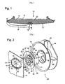
- Figure 1 shows a refrigeration appliance door as an example of a heat-insulating wall according to the invention, with a door handle attached to the door by means of a Schulegteils.
- FIG. 2 is an exploded perspective view of the backing member and a cup separating the backing member from the insulating layer;
- Fig. 3 is an enlarged view of the backing part
- Fig. 4 is a perspective view of the backing part and the cup in the nested state.
- Fig. 1 shows a refrigerator door 10, which by a non-cutting shaping of a Plastic board produced inner lining 11, a heat insulating layer 12 and connected to the inner lining 11 to a door body, serving as the outer skin 13 has outer lining, which by the wetting effect of the polyurethane foam formed in the space defined by the inner lining 11 and the outer skin 13 space insulation 12 is connected to the inner lining 11 to a dimensionally stable structure.
- door handle On the outer skin 13 a bow-like trained, explained in more detail below door handle is fixed to two mounting positions I and II, of which the mounting position 1 is provided to the installation position of the refrigerator door 10 vertically extending side cheeks of the outer skin 13, while the mounting position II in about the middle Width of the door 10 is provided at the front side formed by the outer skin 13.
- the outer skin 13 which is made of sheet steel, is provided with a substantially circular opening 14, in the opening area of which at least two approximately oppositely disposed projections project integrally with integrally formed projections 15, which are stepped in direction towards the heat insulation layer 12 are offset by tapping off.
- a backing member 20 provided therein for insertion into the opening 14 and latching in the manner of a bayonet catch is integrally formed substantially by a hollow cylindrical shaft 21, a base plate 22 substantially closing the shaft 21 at one end, and a frusto-conical sealing lip extending around the shaft 21 23 formed.
- a cross-shaped opening 24 in the base plate 22 is provided for anchoring the door handle therein. Above and below the cross-shaped opening 24 are from the base plate 22 in the axial direction two circular-arc-shaped ribs 25 from. Of the ribs 25 are in turn two spaced from the plate 22 to form a groove 26 retaining wings 27 and two each a radial recess 28 delimiting locking lugs 29, 30 from.
- the backing part 20 is provided to be inserted into the opening 14 of the outer wall 13 from its inside in a rotational orientation in which the retaining wings 27 and locking lugs 29 of a rib 25 each in a cutout 17 between one of the projections 15 and a fixing and retaining lug 16 engage. If after this insertion, the inside of the projection 15 abuts against the base plate 22 of the backing part 10, the latter is rotatable in the opening 14 in an orientation in which one of the base plate 22 facing abutment surface of each retaining wing 27 abuts an outer side of the projection 15.
- the locating and retaining tabs 16 must each engage one of the recesses 28 of the backing member, i. the backing part 20 has to be turned so far that the fixing and retaining lugs 16 respectively pass the latching lug 29 which lies between the retaining wing 27 and the radial recess 28.
- the freedom of rotation of the backing part 20 is limited by the fact that a radially oriented flank 34 (see FIG. 3) facing the retaining wing 27 abuts against the latching lug 29 against a radially oriented edge 18 of the projection 15.
- a formed between this edge 34 and the retaining wing 27 radial slot 31 increases the elastic deformability of the holding wing 27 when the backing member 20 is turned onto an outer skin 13 whose wall thickness is slightly greater than the width of the groove between the retaining wing 27 and the base plate 22nd , and while the fixing and retaining lug 16, the recess 28, the locking lug 29 passes just before the engagement.
- EP 1 032 795 B1 is also ensured by the presence of the slot 31 that the torque required to unscrew the backing part on the outer wall does not increase the closer the radial edge 17 of the flank 34 comes.
- the outer edge of the conical sealing lip 23 presses elastically against the inside of the outer skin 13 over its entire circumference. If the material of the sealing lip 23 were sufficiently supple, this sealing lip 23 could already be provide adequate protection against the passage of foam from the gap to the interior of the backing member 20 (and thus possibly to the outside of the door). However, in order to provide a robust anchorage to the door handle, the material of the backing member 20 must be quite stiff, so that complete foam tightness of the sealing lip 23 is difficult to guarantee.
- cup 40 which is made of a more flexible material than that of the backing piece 20 and is intended to be slipped over the backing sheet 20 attached to the skin 13, the cup 40 facing one of the base sheet 22 open rear side of the shaft 21 of the backing member 20 closes and at the same time forms an effective foam seal on the inside of the outer skin 13 by means of a conical sealing lip 41, which surrounds the sealing lip 23 of the backing member 20 outside.
- the shaft 21 of the backing part 20 is provided with a peripheral rib 32 (FIG. 3), to which a complementary circumferential groove 42 is formed on the inside of the cup 40.
- Cup 40 and backing member 20 are also rotatable with Assistance provided by two diametrically opposed ribs 33 of the shaft 21 and grooves 43 of the cup 40 extending in the direction of attachment.
- the cup 40 is at the level of its bottom with a transversely aligned to the mounting direction flange 44 and a plurality of with respect to the axis of the cup 40 radially and parallel to Aufsteckraum extending wings 45th Mistake.
- the cruciform opening 24 of the backing member 20 fixedly mounted in the skin 13 is intended to insert into the vertical slot of the aperture 24 an approximately T-shaped armature of the door handle and subsequently to engage the shank of the anchor in one of the two horizontal slots extending from the vertical slot Branches of the opening 24 to move, wherein the shaft held by the transverse bar of the armature above and below the branch behind the base plate 22 of the backing member 20 engages.
- the anchor In which of the two branches of the opening 24 of the backing 20 placed centrally in the outer skin 13 the anchor is displaced, depends on the two side cheeks of the outer skin 13, the other end of the door handle is fixed to the position I.
- the cross-shaped opening 24 in the base plate 22 of the backing member 20 can be replaced by any other suitable for fastening the respective desired part shapes.
- a backing member 20 of the type described above may also be used to be mounted in an opening of the inner liner 11 so as to attach to this backing member 20 refrigerated goods carriers of the interior of the refrigerator or telescopic rails on which such refrigerated goods carrier is slidable.
Abstract
Description
Die vorliegende Erfindung betrifft eine wärmeisolierende Wand, insbesondere eine Wand, die Teil einer Tür oder eines Gehäuses eines Kältegeräts ist.The present invention relates to a heat-insulating wall, in particular a wall, which is part of a door or a housing of a refrigerator.
Derartige Wände umfassen herkömmlicherweise eine Isolationsschicht von geringer Festigkeit, die durch wenigstens eine feste Haut begrenzt ist. Wenn Teile an einer solchen Wand befestigt werden müssen, beispielsweise ein Griff an einer Kältegerätetür oder Kühlgutträger im Korpus des Kältegeräts, so geschieht dies häufig mit in einer Öffnung der Haut verankerten Hinterlegteilen, die eine von dem montierten Teil ausgeübte Kraft örtlich verteilt in die Haut einleiten, so dass diese trotz einer geringen Materialstärke in der Lage ist, die Kraft zu tragen.Such walls conventionally comprise a low strength insulation layer bounded by at least one solid skin. When parts have to be fixed to such a wall, for example a handle on a refrigerator door or refrigerated goods in the body of the refrigerator, this often happens with anchored in an opening of the skin backing parts that introduce a force exerted by the mounted part locally distributed in the skin , so that it is able to carry the power despite a low material thickness.
Eine wärmeisolierende Wand nach dem Oberbegriff des Anspruchs 1 ist aus
Aufgabe der vorliegenden Erfindung ist, diese bekannte wärmeisolierende Wand so weiterzubilden, dass eine höhere Toleranz in Bezug auf Schwankungen der Dicke der Haut bzw. des Abstandes der zwei Anlageflächen erreicht wird.Object of the present invention is to develop this known heat-insulating wall so that a higher tolerance in terms of variations in the thickness of the skin or the distance of the two contact surfaces is achieved.
Während bei der bekannten Wand die Anlagefläche des Halteflügels materialschlüssig in die Anschlagflanke übergeht, wird bei der erfindungsgemäßen Wand eine Flexibilität des Halteflügels in der Einführrichtung dadurch erreicht, dass zwischen dem Halteflügel und der Anschlagflanke eine Materialverjüngung vorgesehen ist. Durch die Schwächung der Materialstärke zwischen dem Halteflügel und der Anschlagflanke wird für den Halteflügel in einem gewissen Umfang ein elastisches Verhalten erreicht. Wenn das Hinterlegteil an einer festen Haut montiert werden soll, deren Stärke geringfügig größer als der Abstand zwischen den zwei Anlageflächen ist, so kann der Halteflügel in Einführrichtung geringfügig nachgeben, und das Hinterlegteil kann in die verriegelte Stellung gebracht werden und verharrt stabil in dieser. Das elastische Verhalten des Halteflügels wird durch die Ausbildung der Materialverjüngung als Spalt oder Schlitz anwendungsorientiert besonders einfach bestimmbar.While in the known wall, the contact surface of the retaining wing materially merges into the stop edge, in the wall according to the invention a flexibility of the retaining wing in the insertion direction is achieved in that between the retaining wing and the stop edge, a material taper is provided. Due to the weakening of the material thickness between the holding wing and the stop flank, elastic behavior is achieved for the holding wing to a certain extent. If the backing is to be mounted on a solid skin whose thickness is slightly greater than the distance between the two contact surfaces, the retaining wing in the insertion slightly yield, and the backing member can be brought into the locked position and remains stable in this. The elastic behavior of the holding wing is particularly simple to determine by application of the material taper as a gap or slit.
Vorzugsweise ist die erste Seite der Haut der Isolationsschicht zugewandt, so dass an der fertigen Wand das Hinterlegteil im Wesentlichen in die Isolationsschicht eingebettet ist.The first side of the skin preferably faces the insulation layer, so that the backing part is essentially embedded in the insulation layer on the finished wall.
Bei einer in einer an sich bekannter Weise durch Verfüllen eines Zwischenraumes mit Isolierschaum gebildeten Isolationsschicht ist vorzugsweise das Hinterlegteil in dem Isolierschaum in der verriegelten Stellung immobilisiert.In an insulating layer formed in a manner known per se by filling a gap with insulating foam, the backing part is preferably immobilized in the insulating foam in the locked position.
Eine sich rings um die Öffnung erstreckende, an der ersten Seite der Haut anliegende Dichtlippe des Hinterlegteils kann dazu dienen, den Zutritt des Materials der Isolationsschicht zur Öffnung zu verhindern. Diese Dichtlippe kann gleichzeitig auch als die zweite Anlagefläche des Hinterlegteils dienen.A sealing lip of the backing piece extending around the opening and resting against the first side of the skin can serve to prevent the material of the insulating layer from entering the opening. This sealing lip can simultaneously serve as the second bearing surface of the backing part.
Vorzugsweise ist das Hinterlegteil von der Isolationsschicht durch einen über das Hinterlegteil gestülpten Becher getrennt, von dem ein Rand an der ersten Seite der Haut anliegt. Auch dieser Rand kann wiederum bevorzugt in Form einer kegelförmigen Dichtlippe ausgebildet sein.Preferably, the backing part is separated from the insulating layer by a cup placed over the backing piece, an edge of which rests against the first side of the skin. Again, this edge may again preferably be in the form of a conical sealing lip.
Da der Becher nicht das Gewicht eines an dem Hinterlegteil angreifenden Elements tragen muss, sondern im Wesentlichen nur der Abschirmung der Öffnung von der Isolationsschicht dient, kann er vorteilhaft aus einem flexibleren Material gebildet sein als das Hinterlegteil. Diese Flexibilität begünstigt eine wirksame Abdichtung gegen die Isolationsschicht zwischen der festen Haut und dem Rand des Bechers.Since the cup does not have to bear the weight of an element engaging the backing part, but essentially serves only to shield the opening of the insulation layer, it may advantageously be formed of a more flexible material than the backing part. This flexibility favors effective sealing against the insulating layer between the solid skin and the rim of the cup.
Vorzugsweise ist der Becher mit zur Immobilisierung des Hinterlegteils in die Isolationsschicht vorspringenden Flügeln versehen.Preferably, the cup is provided with wings for immobilizing the backing part in the insulating layer.
Das Hinterlegteil und der Becher sind vorzugsweise drehfest aneinander verrastet, vorzugsweise dadurch, dass von Hinterlegteil und Becher das eine wenigstens eine in der Einführrichtung orientierte Nut und das andere jeweils eine zu der Nut komplementäre Rippe aufweist.The backing piece and the cup are preferably non-rotatably locked to one another, preferably in that of the backing piece and the cup, one has at least one groove oriented in the insertion direction and the other has a rib that is complementary to the groove.
Weitere Merkmale und Vorteile der Erfindung ergeben sich aus der nachfolgenden Beschreibung eines Ausführungsbeispiels mit Bezug auf die beigefügten Figuren. Es zeigen:Further features and advantages of the invention will become apparent from the following description of an embodiment with reference to the accompanying figures. Show it:
Fig. 1 eine Kältegerätetür als Beispiel einer erfindungsgemäßen wärmeisolierenden Wand, mit einem an der Tür mit Hilfe eines Hinterlegteils befestigten Türgriff;Figure 1 shows a refrigeration appliance door as an example of a heat-insulating wall according to the invention, with a door handle attached to the door by means of a Hinterlegteils.
Fig. 2 eine auseinandergezogene perspektivische Ansicht des Hinterlegteils und eines das Hinterlegteil von der Isolationsschicht trennenden Bechers;FIG. 2 is an exploded perspective view of the backing member and a cup separating the backing member from the insulating layer; FIG.
Fig. 3 eine vergrößerte Ansicht des Hinterlegteils; undFig. 3 is an enlarged view of the backing part; and
Fig. 4 eine perspektivische Ansicht des Hinterlegteils und des Bechers im ineinandergefügten Zustand.Fig. 4 is a perspective view of the backing part and the cup in the nested state.
Fig. 1 zeigt eine Kühlschranktür 10, welche eine durch spanlose Formgebung einer Kunststoffplatine erzeugte Innenverkleidung 11, eine Wärmeisolationsschicht 12 und eine mit der Innenverkleidung 11 zu einem Türkorpus verbundene, als Außenhaut 13 dienende Außerverkleidung aufweist, welche durch die benetzende Wirkung der durch Aufschäumen von Polyurethan in dem von der Innenverkleidung 11 und der Außenhaut 13 begrenzten Zwischenraum gebildeten Isolationsschicht 12 mit der Innenverkleidung 11 zu einem formsteifen Gebilde verbunden ist. An der Außenhaut 13 ist ein bügelartig ausgebildeter, weiter unten genauer erläuterter Türgriff an zwei Befestigungspositionen I und II festgesetzt, wovon die Befestigungsposition 1 an den in Einbaulage der Kühlschranktür 10 vertikal verlaufenden Seitenwangen der Außenhaut 13 vorgesehen ist, während die Befestigungsposition II in etwa mittig zur Breite der Tür 10 an deren durch die Außenhaut 13 gebildeter Frontseite vorgesehen ist.Fig. 1 shows a
Wie insbesondere Fig. 2 zeigt ist die aus Stahlblech spanlos geformte Außenhaut 13 zu diesem Zweck mit einer im Wesentlichen kreisförmigen Öffnung 14 versehen, in deren Öffnungsfläche zwei zumindest einander annähernd gegenüberliegend angeordnete, an die Außenhaut einstückig mit angeformte Vorsprünge 15 ragen, welche stufenartig in Richtung zur Wärmeisolationsschicht 12 hin durch Abkröpfen abgesetzt sind. Benachbart zu den abgesetzten Vorsprüngen 15 sind als Rastmittel 16 dienende, einander gegenüberliegende Fixier- und Haltenasen angeordnet, welche wie die Vorsprünge, aber im Gegensatz zu diesen ebenflächig mit dem Rest der Außenhaut 13 ausgeführt sind.As shown particularly in FIG. 2, the
Ein zum Einführen in die Öffnung 14 und Verriegeln in Art eines Bajonettverschlusses darin vorgesehenes Hinterlegteil 20 ist einteilig, im Wesentlichen durch einen hohlzylindrischen Schaft 21, eine den Schaft 21 an einem Ende großenteils verschließende Grundplatte 22 und eine rings um den Schaft 21 verlaufende, kegelstumpfförmige Dichtlippe 23 gebildet. Eine kreuzförmige Öffnung 24 in der Grundplatte 22 ist zur Verankerung des Türgriffs darin vorgesehen. Oberhalb und Unterhalb der kreuzförmigen Öffnung 24 stehen von der Grundplatte 22 in axialer Richtung zwei kreisbogenförmige Rippen 25 ab. Von den Rippen 25 stehen wiederum zwei von der Platte 22 unter Ausbildung einer Nut 26 beabstandete Halteflügel 27 und je zwei eine radiale Aussparung 28 begrenzende Rastnasen 29, 30 ab.A
Das Hinterlegteil 20 ist vorgesehen, um in die Öffnung 14 der Außenwand 13 von ihrer Innenseite her in einer Drehorientierung eingeführt zu werden, in welcher die Halteflügel 27 und Rastnasen 29 einer Rippe 25 jeweils in einen Ausschnitt 17 zwischen einem der Vorsprünge 15 und einer Fixier- und Haltenase 16 eingreifen. Wenn nach diesem Einführen die Innenseite des Vorsprungs 15 an der Grundplatte 22 des Hinterlegteils 10 anliegt, ist letzteres in der Öffnung 14 in eine Orientierung drehbar, in welcher jeweils eine der Grundplatte 22 zugewandte Anschlagfläche jedes Halteflügels 27 an einer Außenseite des Vorsprungs 15 anliegt.The
Um das Hinterlegteil 20 an der Außenhaut 13 zu verriegeln, müssen die Fixier- und Haltenasen 16 jeweils in eine der Aussparungen 28 des Hinterlegteils eingreifen, d.h. das Hinterlegteil 20 muss so weit gedreht werden, dass die Fixier- und Haltenasen 16 jeweils die Rastnase 29 passieren, die zwischen dem Halteflügel 27 und der radialen Aussparung 28 liegt.To lock the
Die Drehbewegungsfreiheit des Hinterlegteils 20 ist dadurch beschränkt, dass eine dem Halteflügel 27 zugewandte, radial orientierte Flanke 34 (siehe Fig. 3) der Rastnase 29 gegen eine radial orientierte Kante 18 des Vorsprungs 15 stößt.The freedom of rotation of the
Ein zwischen dieser Flanke 34 und dem Halteflügel 27 gebildeter radialer Schlitz 31 erhöht die elastische Verformbarkeit des Halteflügels 27, wenn das Hinterlegteil 20 auf eine Außenhaut 13 aufgedreht wird, deren Wandstärke geringfügig größer ist als die Breite der Nut zwischen dem Halteflügel 27 und der Grundplatte 22, und während die Fixier- und Haltenase 16 kurz vor dem Einrasten die Aussparung 28 die Rastnase 29 passiert. Anders als bei dem herkömmlichen Hinterlegteil nach
Wenn das Hinterlegteil 20 auf die Außenhaut 13 aufgedreht und an dieser verrastet ist, drückt der äußere Rand der kegelförmigen Dichtlippe 23 auf seinem gesamten Umfang elastisch gegen die Innenseite der Außenhaut 13. Wenn das Material der Dichtlippe 23 ausreichend geschmeidig wäre, könnte diese Dichtlippe 23 bereits einen ausreichenden Schutz gegen das Hindurchtreten von Schaum aus dem Zwischenraum ins Innere des Hinterlegteils 20 (und damit eventuell an die Außenseite der Tür) darstellen. Um eine robuste Verankerung für den Türgriff zu ergeben, muss das Material des Hinterlegteils 20 jedoch ziemlich steif sein, so dass eine vollständige Schaumdichtigkeit der Dichtlippe 23 schwierig zu garantieren ist. Dieses Problem wird jedoch mit Hilfe eines Bechers 40 gelöst, der aus einem flexibleren Material als dem des Hinterlegteils 20 gefertigt ist und vorgesehen ist, um über das an der Außenhaut 13 befestigte Hinterlegteil 20 gestülpt zu werden, wobei der Becher 40 eine der Grundplatte 22 gegenüberliegende offene Rückseite des Schafts 21 des Hinterlegteils 20 verschließt und gleichzeitig mit Hilfe einer kegelförmigen Dichtlippe 41, welche die Dichtlippe 23 des Hinterlegteils 20 außen umgibt, eine wirksame Schaumabdichtung an der Innenseite der Außenhaut 13 bildet.If the
Um den Becher 40 an dem Hinterlegteil 20 in Aufsteckrichtung zu verankern und einen zum Abdichten ausreichenden Druck der Dichtlippe 41 gegen die Außenhaut 13 zu gewährleisten, ist der Schaft 21 des Hinterlegteils 20 mit einer umlaufenden Rippe 32 (Fig. 3) versehen, zu der eine komplementäre umlaufende Nut 42 an der Innenseite des Bechers 40 gebildet ist. Becher 40 und Hinterlegteil 20 sind ferner drehfest mit Hilfe von zwei sich in Aufsteckrichtung erstreckenden, diametral gegenüberliegenden Rippen 33 des Schafts 21 und Nuten 43 des Bechers 40 versehen. Zur festen Verankerung des Bechers 40 im verfestigten Schaummaterial der Wärmeisolationsschicht 12 ist der Becher 40 in Höhe seines Bodens mit einem quer zur Aufsteckrichtung ausgerichteten Flansch 44 sowie mit einer Mehrzahl von sich in Bezug auf die Achse des Bechers 40 radial und parallel zur Aufsteckrichtung erstreckenden Flügeln 45 versehen.In order to anchor the
Die kreuzförmige Öffnung 24 des in der Außenhaut 13 fest montierten Hinterlegteils 20 ist vorgesehen, um in den vertikalen Schlitz der Öffnung 24 einen in etwa T-förmigen Anker des Türgriffs einzuführen und anschließend den Schaft des Ankers in einen der zwei von dem vertikalen Schlitz ausgehenden horizontalen Zweige der Öffnung 24 zu verschieben, wobei der von dem Schaft gehaltene Querbalken des Ankers oberhalb und unterhalb des Zweiges hinter der Grundplatte 22 des Hinterlegteils 20 eingreift. In welchem der zwei Zweige der Öffnung 24 des mittig in der Außenhaut 13 platzierten Hinterlegteils 20 der Anker verschoben wird, hängt davon ab, an der zwei Seitenwangen der Außenhaut 13 das jeweils andere Ende des Türgriffs an der Position I befestigt wird.The cruciform opening 24 of the
Es liegt auf der Hand, dass zur Befestigung beliebiger anderer Teile die kreuzförmige Öffnung 24 in der Grundplatte 22 des Hinterlegteils 20 durch beliebige andere zur Befestigung des jeweils gewünschten Teils geeignete Formgebungen ersetzt werden kann. So kann ein Hinterlegteil 20 vom oben beschriebenen Typ beispielsweise auch eingesetzt werden, um in einer Öffnung der Innenverkleidung 11 montiert zu werden, um so an diesem Hinterlegteil 20 Kühlgutträger des Innenraums des Kühlschranks oder Teleskopschienen, auf denen ein solcher Kühlgutträger verschiebbar ist, anzubringen.It is obvious that for fixing any other parts, the cross-shaped opening 24 in the
Claims (14)
- Thermally insulating wall with at least one solid skin (13), which bounds an insulating layer (12), and a backing part (20), which is anchored in an opening (14) of the skin (13) and which in a first rotational setting is introduced into the opening (14) from a first side of the solid skin (13) and is brought by rotation about the direction of introduction into a locked setting in which a contact surface of a retaining lobe (27) of the backing part (20) bears against the second side of the solid skin (13), a second contact surface (22) of the backing part (20) bears against the first side of the solid skin (13) and an abutment flank (34) of the backing part (20) abuts a radially oriented edge (18) of the opening (14), characterised in that a material narrowing arranged transversely to the direction of rotation is provided between the retaining lobe (27) and the abutment flank (34).
- Thermally insulating wall according to claim 1, characterised in that the material tapering is formed to be open at the edge towards the free edge of the retaining lobe (27) and is led radially inwardly.
- Thermally insulating wall according to claim 1 or 2, characterised in that the material tapering is formed as a gap which penetrates the material thickness of the retaining lobe (27) and at the gap base of which a connecting web between retaining lobe (27) and the abutment flank (34) is formed.
- Thermally insulating wall according to claim 1, characterised in that the first side of the skin (13) faces the insulating layer (12).
- Thermally insulating wall according to claim 1 or 4, characterised in that the insulating layer (12) is formed by filling an intermediate space with insulating foam and the backing part (20) is immobilised in the insulating foam in the locked setting.
- Thermally insulating wall according to one of the preceding claims, characterised in that the backing part (20) carries a sealing lip (23, 41) which extends annularly around the opening (14) and bears against the first side of the skin (13).
- Thermally insulating wall according to one of the preceding claims, characterised in that the backing part (20) is separated from the insulating layer (12) by a cup (40) which is inverted over the backing part (20) and which bears by the one edge (41) against the first side of the skin (13).
- Thermally insulating wall according to claim 7, characterised in that the edge of the cup (40) is formed by a conical sealing lip (41).
- Thermally insulating wall according to claim 7 or 8, characterised in that the cup (40) is formed from a more flexible material than the backing part (20).
- Thermally insulating wall according to claim 7, 8 or 9, characterised in that the cup (40) is provided with vanes (45) protruding into the insulating layer (12).
- Thermally insulating wall according to one of claims 7 to 10, characterised in that the backing part (20) and the cup (40) are detented with one another to be secure against relative rotation.
- Thermally insulting wall according to claim 11, characterised in that of the backing part (20) and cup (40) one has at least one groove (43) oriented in the direction of introduction and the other has a respective rib (33) complementary with the groove (43).
- Thermally insulating wall for a refrigerating appliance according to one of the preceding claims, characterised in that the skin (13) is an outer wall of a door (10) of the refrigerating appliance and a door handle is anchored at the backing part (20).
- Thermally insulating wall for a refrigerating appliance according to one of claims 1 to 10, characterised in that the skin (13) is an inner container (11) of the refrigerating appliance and a cooling stock carrier is anchored at the backing part (20).
Applications Claiming Priority (2)
| Application Number | Priority Date | Filing Date | Title |
|---|---|---|---|
| DE102004012539A DE102004012539A1 (en) | 2004-03-15 | 2004-03-15 | Heat-insulating wall |
| PCT/EP2005/051121 WO2005090879A2 (en) | 2004-03-15 | 2005-03-11 | Thermal-insulated wall |
Publications (2)
| Publication Number | Publication Date |
|---|---|
| EP1728032A2 EP1728032A2 (en) | 2006-12-06 |
| EP1728032B1 true EP1728032B1 (en) | 2007-09-12 |
Family
ID=34962093
Family Applications (1)
| Application Number | Title | Priority Date | Filing Date |
|---|---|---|---|
| EP05717013A Active EP1728032B1 (en) | 2004-03-15 | 2005-03-11 | Thermal-insulated wall |
Country Status (8)
| Country | Link |
|---|---|
| EP (1) | EP1728032B1 (en) |
| CN (1) | CN100472157C (en) |
| AT (1) | ATE373215T1 (en) |
| BR (1) | BRPI0508268A (en) |
| DE (2) | DE102004012539A1 (en) |
| ES (1) | ES2293548T3 (en) |
| RU (1) | RU2377480C2 (en) |
| WO (1) | WO2005090879A2 (en) |
Families Citing this family (5)
| Publication number | Priority date | Publication date | Assignee | Title |
|---|---|---|---|---|
| KR100776271B1 (en) * | 2007-01-26 | 2007-11-15 | 삼성광주전자 주식회사 | A refrigerator |
| DE102009002444A1 (en) * | 2009-04-16 | 2010-10-21 | BSH Bosch und Siemens Hausgeräte GmbH | The refrigerator |
| EP2938946A1 (en) * | 2012-12-31 | 2015-11-04 | Arçelik Anonim Sirketi | A refrigerator comprising a door handle |
| DE102015221431A1 (en) * | 2015-11-02 | 2017-05-04 | BSH Hausgeräte GmbH | Refrigerating appliance with backing part and method for producing a refrigeration appliance with backing part |
| CN209637377U (en) * | 2018-12-05 | 2019-11-15 | 福建西河卫浴科技有限公司 | A kind of handle component and shower house |
Family Cites Families (2)
| Publication number | Priority date | Publication date | Assignee | Title |
|---|---|---|---|---|
| DE1112265B (en) * | 1952-07-25 | 1961-08-03 | Saba Gmbh | The exchangeable supports are used to support shelves in cupboard-like containers, in particular support plates and grids in ice cream and refrigerator cabinets |
| DE19751310A1 (en) * | 1997-11-19 | 1999-05-20 | Bosch Siemens Hausgeraete | Refrigerator |
-
2004
- 2004-03-15 DE DE102004012539A patent/DE102004012539A1/en not_active Withdrawn
-
2005
- 2005-03-11 AT AT05717013T patent/ATE373215T1/en not_active IP Right Cessation
- 2005-03-11 DE DE502005001489T patent/DE502005001489D1/en active Active
- 2005-03-11 RU RU2006130850/12A patent/RU2377480C2/en not_active IP Right Cessation
- 2005-03-11 EP EP05717013A patent/EP1728032B1/en active Active
- 2005-03-11 CN CNB2005800083215A patent/CN100472157C/en not_active Expired - Fee Related
- 2005-03-11 ES ES05717013T patent/ES2293548T3/en active Active
- 2005-03-11 WO PCT/EP2005/051121 patent/WO2005090879A2/en active IP Right Grant
- 2005-03-11 BR BRPI0508268-4A patent/BRPI0508268A/en not_active IP Right Cessation
Also Published As
| Publication number | Publication date |
|---|---|
| ATE373215T1 (en) | 2007-09-15 |
| BRPI0508268A (en) | 2007-07-31 |
| RU2377480C2 (en) | 2009-12-27 |
| CN100472157C (en) | 2009-03-25 |
| ES2293548T3 (en) | 2008-03-16 |
| DE102004012539A1 (en) | 2005-10-06 |
| CN1934402A (en) | 2007-03-21 |
| RU2006130850A (en) | 2008-04-27 |
| EP1728032A2 (en) | 2006-12-06 |
| WO2005090879A3 (en) | 2006-01-12 |
| WO2005090879A2 (en) | 2005-09-29 |
| DE502005001489D1 (en) | 2007-10-25 |
Similar Documents
| Publication | Publication Date | Title |
|---|---|---|
| AT404858B (en) | DOOR STOP PART FOR HINGE FURNITURE DESIGNED AS A HINGE POT | |
| DE60100608T2 (en) | Waterproof eyelet | |
| EP0530348B1 (en) | Plastic mounting pin designed in particular for furniture fittings | |
| DE19930728B4 (en) | Anchor for fixing an object to a carrier made of flat material | |
| EP1728032B1 (en) | Thermal-insulated wall | |
| WO2005060331A2 (en) | Device for connecting a carrier part and an add-on piece | |
| EP0264342B1 (en) | Adjustable fastening means for assembling two construction parts | |
| EP2206856B1 (en) | Actuation handle | |
| WO1991011631A1 (en) | Self-drilling fastening | |
| EP0750554B1 (en) | Wiper arm for a windscreen wiper system, especially for motor vehicles | |
| DE19755899C2 (en) | Drive unit for adjustment devices | |
| DE102019126620A1 (en) | Fastening device | |
| DE10300991A1 (en) | Compensatory screw connection, comprising radial projection at outer thread acting in combination with stop located at inner thread | |
| EP1103771B1 (en) | Refrigerator door | |
| EP0754827B1 (en) | Device for releasable and non-sliding mounting of a handle on a bearing element, especially for door handles or window handles | |
| EP2019953A1 (en) | Door for a separable interior space | |
| DE19805949A1 (en) | Foot mat fixing element for vehicle | |
| EP3363969B1 (en) | Actuation handle | |
| EP0942121B1 (en) | Escutcheon for a door fitting | |
| EP1803187A1 (en) | Antenna holding device | |
| DE102010008040A1 (en) | Device for detachably connecting components i.e. lining plates, of automobile, has locking projections pressing anchorage sections from hollow area, such anchorage sections sink outwardly to release locking between locking elements | |
| DE4336326C5 (en) | Door hinged part designed as hinge cup for furniture hinges | |
| DE3732895C2 (en) | ||
| WO2019145123A1 (en) | Non-detachable securing device | |
| EP0344424B1 (en) | Fastener locking by rotation |
Legal Events
| Date | Code | Title | Description |
|---|---|---|---|
| PUAI | Public reference made under article 153(3) epc to a published international application that has entered the european phase |
Free format text: ORIGINAL CODE: 0009012 |
|
| 17P | Request for examination filed |
Effective date: 20061016 |
|
| AK | Designated contracting states |
Kind code of ref document: A2 Designated state(s): AT BE BG CH CY CZ DE DK EE ES FI FR GB GR HU IE IS IT LI LT LU MC NL PL PT RO SE SI SK TR |
|
| GRAP | Despatch of communication of intention to grant a patent |
Free format text: ORIGINAL CODE: EPIDOSNIGR1 |
|
| DAX | Request for extension of the european patent (deleted) | ||
| GRAS | Grant fee paid |
Free format text: ORIGINAL CODE: EPIDOSNIGR3 |
|
| GRAA | (expected) grant |
Free format text: ORIGINAL CODE: 0009210 |
|
| AK | Designated contracting states |
Kind code of ref document: B1 Designated state(s): AT BE BG CH CY CZ DE DK EE ES FI FR GB GR HU IE IS IT LI LT LU MC NL PL PT RO SE SI SK TR |
|
| REG | Reference to a national code |
Ref country code: GB Ref legal event code: FG4D Free format text: NOT ENGLISH |
|
| REG | Reference to a national code |
Ref country code: CH Ref legal event code: EP |
|
| GBT | Gb: translation of ep patent filed (gb section 77(6)(a)/1977) |
Effective date: 20070912 |
|
| REF | Corresponds to: |
Ref document number: 502005001489 Country of ref document: DE Date of ref document: 20071025 Kind code of ref document: P |
|
| REG | Reference to a national code |
Ref country code: IE Ref legal event code: FG4D Free format text: LANGUAGE OF EP DOCUMENT: GERMAN |
|
| REG | Reference to a national code |
Ref country code: SE Ref legal event code: TRGR |
|
| ET | Fr: translation filed | ||
| PG25 | Lapsed in a contracting state [announced via postgrant information from national office to epo] |
Ref country code: LT Free format text: LAPSE BECAUSE OF FAILURE TO SUBMIT A TRANSLATION OF THE DESCRIPTION OR TO PAY THE FEE WITHIN THE PRESCRIBED TIME-LIMIT Effective date: 20070912 Ref country code: FI Free format text: LAPSE BECAUSE OF FAILURE TO SUBMIT A TRANSLATION OF THE DESCRIPTION OR TO PAY THE FEE WITHIN THE PRESCRIBED TIME-LIMIT Effective date: 20070912 |
|
| PG25 | Lapsed in a contracting state [announced via postgrant information from national office to epo] |
Ref country code: PL Free format text: LAPSE BECAUSE OF FAILURE TO SUBMIT A TRANSLATION OF THE DESCRIPTION OR TO PAY THE FEE WITHIN THE PRESCRIBED TIME-LIMIT Effective date: 20070912 |
|
| NLV1 | Nl: lapsed or annulled due to failure to fulfill the requirements of art. 29p and 29m of the patents act | ||
| REG | Reference to a national code |
Ref country code: ES Ref legal event code: FG2A Ref document number: 2293548 Country of ref document: ES Kind code of ref document: T3 |
|
| PG25 | Lapsed in a contracting state [announced via postgrant information from national office to epo] |
Ref country code: GR Free format text: LAPSE BECAUSE OF FAILURE TO SUBMIT A TRANSLATION OF THE DESCRIPTION OR TO PAY THE FEE WITHIN THE PRESCRIBED TIME-LIMIT Effective date: 20071213 Ref country code: NL Free format text: LAPSE BECAUSE OF FAILURE TO SUBMIT A TRANSLATION OF THE DESCRIPTION OR TO PAY THE FEE WITHIN THE PRESCRIBED TIME-LIMIT Effective date: 20070912 |
|
| REG | Reference to a national code |
Ref country code: IE Ref legal event code: FD4D |
|
| PG25 | Lapsed in a contracting state [announced via postgrant information from national office to epo] |
Ref country code: CZ Free format text: LAPSE BECAUSE OF FAILURE TO SUBMIT A TRANSLATION OF THE DESCRIPTION OR TO PAY THE FEE WITHIN THE PRESCRIBED TIME-LIMIT Effective date: 20070912 Ref country code: IS Free format text: LAPSE BECAUSE OF FAILURE TO SUBMIT A TRANSLATION OF THE DESCRIPTION OR TO PAY THE FEE WITHIN THE PRESCRIBED TIME-LIMIT Effective date: 20080112 Ref country code: PT Free format text: LAPSE BECAUSE OF FAILURE TO SUBMIT A TRANSLATION OF THE DESCRIPTION OR TO PAY THE FEE WITHIN THE PRESCRIBED TIME-LIMIT Effective date: 20080212 Ref country code: SK Free format text: LAPSE BECAUSE OF FAILURE TO SUBMIT A TRANSLATION OF THE DESCRIPTION OR TO PAY THE FEE WITHIN THE PRESCRIBED TIME-LIMIT Effective date: 20070912 |
|
| PG25 | Lapsed in a contracting state [announced via postgrant information from national office to epo] |
Ref country code: RO Free format text: LAPSE BECAUSE OF FAILURE TO SUBMIT A TRANSLATION OF THE DESCRIPTION OR TO PAY THE FEE WITHIN THE PRESCRIBED TIME-LIMIT Effective date: 20070912 |
|
| PLBE | No opposition filed within time limit |
Free format text: ORIGINAL CODE: 0009261 |
|
| STAA | Information on the status of an ep patent application or granted ep patent |
Free format text: STATUS: NO OPPOSITION FILED WITHIN TIME LIMIT |
|
| PG25 | Lapsed in a contracting state [announced via postgrant information from national office to epo] |
Ref country code: DK Free format text: LAPSE BECAUSE OF FAILURE TO SUBMIT A TRANSLATION OF THE DESCRIPTION OR TO PAY THE FEE WITHIN THE PRESCRIBED TIME-LIMIT Effective date: 20070912 |
|
| 26N | No opposition filed |
Effective date: 20080613 |
|
| BERE | Be: lapsed |
Owner name: BSH BOSCH UND SIEMENS HAUSGERATE G.M.B.H. Effective date: 20080331 |
|
| PG25 | Lapsed in a contracting state [announced via postgrant information from national office to epo] |
Ref country code: IE Free format text: LAPSE BECAUSE OF FAILURE TO SUBMIT A TRANSLATION OF THE DESCRIPTION OR TO PAY THE FEE WITHIN THE PRESCRIBED TIME-LIMIT Effective date: 20070912 Ref country code: MC Free format text: LAPSE BECAUSE OF NON-PAYMENT OF DUE FEES Effective date: 20080331 |
|
| PG25 | Lapsed in a contracting state [announced via postgrant information from national office to epo] |
Ref country code: EE Free format text: LAPSE BECAUSE OF FAILURE TO SUBMIT A TRANSLATION OF THE DESCRIPTION OR TO PAY THE FEE WITHIN THE PRESCRIBED TIME-LIMIT Effective date: 20070912 |
|
| PG25 | Lapsed in a contracting state [announced via postgrant information from national office to epo] |
Ref country code: BE Free format text: LAPSE BECAUSE OF NON-PAYMENT OF DUE FEES Effective date: 20080331 |
|
| PG25 | Lapsed in a contracting state [announced via postgrant information from national office to epo] |
Ref country code: SI Free format text: LAPSE BECAUSE OF FAILURE TO SUBMIT A TRANSLATION OF THE DESCRIPTION OR TO PAY THE FEE WITHIN THE PRESCRIBED TIME-LIMIT Effective date: 20070912 |
|
| PG25 | Lapsed in a contracting state [announced via postgrant information from national office to epo] |
Ref country code: CY Free format text: LAPSE BECAUSE OF FAILURE TO SUBMIT A TRANSLATION OF THE DESCRIPTION OR TO PAY THE FEE WITHIN THE PRESCRIBED TIME-LIMIT Effective date: 20070912 |
|
| PG25 | Lapsed in a contracting state [announced via postgrant information from national office to epo] |
Ref country code: BG Free format text: LAPSE BECAUSE OF FAILURE TO SUBMIT A TRANSLATION OF THE DESCRIPTION OR TO PAY THE FEE WITHIN THE PRESCRIBED TIME-LIMIT Effective date: 20071212 Ref country code: AT Free format text: LAPSE BECAUSE OF NON-PAYMENT OF DUE FEES Effective date: 20080311 |
|
| REG | Reference to a national code |
Ref country code: CH Ref legal event code: PL |
|
| PG25 | Lapsed in a contracting state [announced via postgrant information from national office to epo] |
Ref country code: LI Free format text: LAPSE BECAUSE OF NON-PAYMENT OF DUE FEES Effective date: 20090331 Ref country code: CH Free format text: LAPSE BECAUSE OF NON-PAYMENT OF DUE FEES Effective date: 20090331 |
|
| PG25 | Lapsed in a contracting state [announced via postgrant information from national office to epo] |
Ref country code: LU Free format text: LAPSE BECAUSE OF NON-PAYMENT OF DUE FEES Effective date: 20080311 Ref country code: HU Free format text: LAPSE BECAUSE OF FAILURE TO SUBMIT A TRANSLATION OF THE DESCRIPTION OR TO PAY THE FEE WITHIN THE PRESCRIBED TIME-LIMIT Effective date: 20080313 |
|
| PGFP | Annual fee paid to national office [announced via postgrant information from national office to epo] |
Ref country code: SE Payment date: 20120322 Year of fee payment: 8 |
|
| REG | Reference to a national code |
Ref country code: SE Ref legal event code: EUG |
|
| PG25 | Lapsed in a contracting state [announced via postgrant information from national office to epo] |
Ref country code: SE Free format text: LAPSE BECAUSE OF NON-PAYMENT OF DUE FEES Effective date: 20130312 |
|
| REG | Reference to a national code |
Ref country code: FR Ref legal event code: PLFP Year of fee payment: 11 |
|
| REG | Reference to a national code |
Ref country code: DE Ref legal event code: R081 Ref document number: 502005001489 Country of ref document: DE Owner name: BSH HAUSGERAETE GMBH, DE Free format text: FORMER OWNER: BSH BOSCH UND SIEMENS HAUSGERAETE GMBH, 81739 MUENCHEN, DE Effective date: 20150407 |
|
| REG | Reference to a national code |
Ref country code: ES Ref legal event code: PC2A Owner name: BSH HAUSGERATE GMBH Effective date: 20150527 |
|
| REG | Reference to a national code |
Ref country code: FR Ref legal event code: CD Owner name: BSH HAUSGERATE GMBH Effective date: 20151022 |
|
| REG | Reference to a national code |
Ref country code: FR Ref legal event code: PLFP Year of fee payment: 12 |
|
| PGFP | Annual fee paid to national office [announced via postgrant information from national office to epo] |
Ref country code: ES Payment date: 20160322 Year of fee payment: 12 |
|
| PGFP | Annual fee paid to national office [announced via postgrant information from national office to epo] |
Ref country code: GB Payment date: 20160322 Year of fee payment: 12 Ref country code: FR Payment date: 20160322 Year of fee payment: 12 |
|
| GBPC | Gb: european patent ceased through non-payment of renewal fee |
Effective date: 20170311 |
|
| REG | Reference to a national code |
Ref country code: FR Ref legal event code: ST Effective date: 20171130 |
|
| PG25 | Lapsed in a contracting state [announced via postgrant information from national office to epo] |
Ref country code: FR Free format text: LAPSE BECAUSE OF NON-PAYMENT OF DUE FEES Effective date: 20170331 |
|
| PG25 | Lapsed in a contracting state [announced via postgrant information from national office to epo] |
Ref country code: GB Free format text: LAPSE BECAUSE OF NON-PAYMENT OF DUE FEES Effective date: 20170311 |
|
| REG | Reference to a national code |
Ref country code: ES Ref legal event code: FD2A Effective date: 20180703 |
|
| PG25 | Lapsed in a contracting state [announced via postgrant information from national office to epo] |
Ref country code: ES Free format text: LAPSE BECAUSE OF NON-PAYMENT OF DUE FEES Effective date: 20170312 |
|
| PGFP | Annual fee paid to national office [announced via postgrant information from national office to epo] |
Ref country code: DE Payment date: 20220331 Year of fee payment: 18 |
|
| PGFP | Annual fee paid to national office [announced via postgrant information from national office to epo] |
Ref country code: TR Payment date: 20220228 Year of fee payment: 18 |
|
| PGFP | Annual fee paid to national office [announced via postgrant information from national office to epo] |
Ref country code: IT Payment date: 20220331 Year of fee payment: 18 |
|
| REG | Reference to a national code |
Ref country code: DE Ref legal event code: R119 Ref document number: 502005001489 Country of ref document: DE |
|
| PG25 | Lapsed in a contracting state [announced via postgrant information from national office to epo] |
Ref country code: DE Free format text: LAPSE BECAUSE OF NON-PAYMENT OF DUE FEES Effective date: 20231003 |