EP0754827B1 - Device for releasable and non-sliding mounting of a handle on a bearing element, especially for door handles or window handles - Google Patents
Device for releasable and non-sliding mounting of a handle on a bearing element, especially for door handles or window handles Download PDFInfo
- Publication number
- EP0754827B1 EP0754827B1 EP96111472A EP96111472A EP0754827B1 EP 0754827 B1 EP0754827 B1 EP 0754827B1 EP 96111472 A EP96111472 A EP 96111472A EP 96111472 A EP96111472 A EP 96111472A EP 0754827 B1 EP0754827 B1 EP 0754827B1
- Authority
- EP
- European Patent Office
- Prior art keywords
- bearing
- hole
- spreading
- arms
- groove
- Prior art date
- Legal status (The legal status is an assumption and is not a legal conclusion. Google has not performed a legal analysis and makes no representation as to the accuracy of the status listed.)
- Expired - Lifetime
Links
Images


Classifications
-
- E—FIXED CONSTRUCTIONS
- E05—LOCKS; KEYS; WINDOW OR DOOR FITTINGS; SAFES
- E05B—LOCKS; ACCESSORIES THEREFOR; HANDCUFFS
- E05B3/00—Fastening knobs or handles to lock or latch parts
- E05B3/06—Fastening knobs or handles to lock or latch parts by means arranged in or on the rose or escutcheon
Definitions
- the invention relates to a device of the type specified in the preamble of claim 1.
- the spreader In a known device of this type (DE 36 04 115 A1), the spreader consists of two arms forming the latch plates, which are pivotally mounted on a riveted to the bearing part pivot pin and resiliently biased by a mounted on the pivot pin leg spring against each other.
- the two arms For spreading the two arms is a displaceably mounted in the bearing part Sp Drschieber, which can be actuated from the outside by means of a tool. Since the arms and the Sp DrISSschieber preferably consist of thin sheet metal parts, so that the bearing part can be kept small and flat as a whole, there is a risk that the Sp Schwarzschieber is pushed in use on the arms, instead of between them, so that a sensitive Actuating mechanism results.
- the published patent application DE 26 29 219 discloses a rotary handle for windows, doors od. Like. With a arranged on a wing or frame rosette and a handle. The handle is rotatably received in the rosette, that engages a leg of a substantially V-shaped spring in a groove attached to a handle of the handle groove. The inserted in a cavity spring can be solved for releasing the handle of the rosette by inserting a corresponding tool from the groove of the handle.
- the invention is therefore based on the object, the device of the type described initially in such a way that it allows safe operation and can be seen immediately, in which state the spreading is.
- the invention has the advantage that the spreading of the expansion part can be made directly with an externally insertable tool and the previously required expansion slide is no longer needed.
- the position of the two arms can be controlled by the also the insertion of the tool serving Entriegelungsloch from the outside, an overall easy to handle and reliable operating mechanism is obtained.
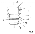
- a conventional, only partially illustrated door handle which has an example consisting of steel insert 2 and a neck portion 3, which by a plastic existing sheath of the insert 2 is formed and, for example, has a cylindrical, an axis 4 having contour.
- the axis 4 in the assembled state of the device, the common longitudinal axis of all parts and at the same time the axis of rotation for the handle 1.
- the neck portion 3 terminates at an end face 5.
- Fig. 3 shows, the insert 2 with one of the end face.
- actuating element 10 for a lock nut or the like In the free end of the bearing portion 6, an actuating element 10 for a lock nut or the like., For example, a conventional Spuchervierkant be used in a conventional manner.
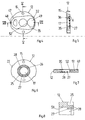
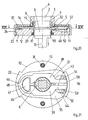
- the apparatus further comprises a bearing part 11, which is preferably formed in two parts and consists of e.g. made of plastic base 12 and an upper part 14 made of steel.
- Both parts 12, 14 are preferably circular as in conventional rosettes and formed as a thin, substantially plane-parallel discs.
- both parts 12, 14 have screw holes 15, 16 which can be aligned with one another for fastening screws, threaded sleeves or the like.
- the lower part 12 and the upper part 14 are also provided with coaxial with each other and coaxial with the axis 4, cylindrical passages 17, 18 which serve to receive the bearing portion 6 and have a substantially the diameter of the bearing portion 6 corresponding diameter.
- the passage 18 of the upper part 14 is surrounded by a bearing collar 19 which protrudes from the top or front of the upper part 14 upwards or from and expediently forms a circumferential, closed bearing surface.
- the top 14 has at its outer periphery a downwardly projecting, e.g. cylindrical peripheral wall 20 in the assembled state, i. with inserted in it lower part 12 (Fig. 1), whose peripheral surface engages with a clamping seat, and whose height is dimensioned so that it is flush with the underside of the lower part 12 in the mounted state.
- the peripheral wall 20 is provided with two sector-shaped cutouts 21 (FIGS. 9, 10) which, when the lower part 12 is inlaid, receive two lugs 22 provided on its edge and correspondingly sector-shaped, which have undercut lugs 23 on their outer circumference (FIG. These interact with their associated undercuts on the inner circumferential surface of a cap 24 together, which is placed after the mounting of the bearing part 11 in the manner shown in FIG. 1 manner on this, after it Cover the outside.
- coaxial groove 25 (Fig. 6) is incorporated, through which an adjacent to the passage 17 peripheral wall portion 26 is formed with a reduced wall thickness. This is subdivided by slots 27 parallel to the axis of the passage 17 into a plurality of elastically yielding lamellae 28 (FIGS. 6 and 8) which, owing to the small wall thickness, are limitedly pivotable about their foot sections in the radial direction.
- the depth of the groove 25 is freely selectable and extends for example over one or two thirds of the thickness of the lower part 12.
- an elastic element 29 e.g. an o-ring, inserted (Fig. 1), which biases the lamellae 28 radially towards the passage 17 so as to define a portion of the passage 17, whose cross-section compared to the not provided with the groove 25 portion of the passage 17 something is reduced.
- the circumferential bearing groove 9 of the handle 1 has, as shown particularly in FIGS. 1 and 3, a diameter substantially corresponding to the diameter of the bearing collar 19.
- the bearing groove 9 preferably has a slightly greater width than the wall thickness of the bearing collar 19 of the upper part 14 corresponds.
- the depth of the bearing groove 9 corresponds substantially to the height of the bearing collar 19 or something more.
- the bearing collar 19 can be arranged with the usual bearing clearance substantially coaxially in the bearing groove 9.
- the bearing groove 9 serves the purpose that the upper part 14 can perform limited tilting movements relative to the axis 4 when introduced into the bearing groove 9 bearing collar 19.
- a radially inner, the bearing groove 9 bounding inner wall 30 ( Figure 3) of the neck portion 3 is preferably formed slightly conical or frustoconical, with its diameter gradually decreases towards the free end.
- the inner diameter of the bearing collar 19 corresponds approximately to the diameter of the inner wall 30 at a location near the bottom of the bearing groove 9 location.
- the bearing part 11 is attached to a door leaf, not shown, by the screw holes 15, 16 and the cutouts 21 and the projections 22 of the lower and upper parts 12, 14 are aligned correspondingly to each other and from Fig. 2 apparent fasteners 31 are inserted into the screw holes 15, 16.
- the cap 24 is clipped in accordance with FIG. 1.
- the parts 12, 14 and 24 form a rosette, wherein the free ends of the lamellae 28 facing the door leaf with the required small distance, while the bearing collar 19 projects upwardly or slightly from a receiving opening 32 of the cap 24.
- the bearing portion 6 of the handle 1 is now inserted axially into the passages 17, 18 (FIGS. 6 and 9) until the bearing collar 19 is completely received in the bearing groove 9 and the front end of the neck portion 3 in the receiving aperture 32 is (FIG. 12).
- the bearing portion 6 and the axis 4 to the axis of the passages 17 and 18 of the bearing collar 19 with the usual bearing clearance in the bearing groove 9, while the Lagerabschitt 6 coaxial in the passage 17 formed by the slats 28 of the lower part 12th is stored.
- the inner wall 30 pivot due to the increased width of the bearing groove 9 and its conical design relative to the bearing collar 19, while anderseit the bearing portion 6 is mounted pivotably in the region of the fins 28.
- the inner diameter of not provided with the fins 28 portion of the passage 17 and the inner diameter of the passage 18 of the upper part 14, where they interact with the bearing portion 6, each have a slightly larger diameter than the bearing portion 6 or that the respective material properties (eg plastic) allow such Verschwenkache due to elastic deformation.
- the handle 1 is rotatably mounted in such pivot positions on two relatively large spaced locations, namely on the one hand by the bearing collar 19 on the inner wall 30 and the other by means of the bearing portion 6 in the lower part 12.
- the first-mentioned bearing acts as a self-aligning bearing, which also allows the usual rotational movements of the handle 1, while the other bearing acts as an elastic compensation bearing.
- the angle ⁇ for example, on both sides of the axis 4 each 1.5 ° and a total of 3 °, thus resulting in assembly inaccuracies that are the cause of such minor pivoting of the axis 4 relative to the bearing axis, a stable and secure Drehlagerung of the equipment.
- the described type of storage of the equipment part 1 is used with particular advantage in combination with the device explained below for axially non-displaceable attachment of the handle 1 on the bearing part 11.
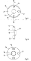
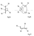
- the lower part 12 has on its top or front side a recess 35 surrounding the passage 17 (FIG. 5) with a bottom 36, which in FIG is arranged substantially parallel to the lower or rear side of the lower part 12.
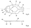
- the recess 35 serves to receive a spreading part 37 (FIGS. 2, 13, 14), which preferably consists of a sheet-metal stamped part produced in one piece.
- the spreading member 37 has two mirror-inverted, substantially parallel arms 38, 39 which are provided in a central region with concave cutouts 40, 41, the surfaces facing each other adapted to the peripheral surface of the bottom of the circumferential groove 8 of the bearing portion 6 form (Fig. Fig. 3).
- the thickness of the arms 38, 39 is smaller than the width of the circumferential groove 8 at least in this area.
- the two arms 38, 39 are connected at one end by an at least partially elastically bendable web 42 and at the opposite, free end with end portions 43, 44 are provided, which are arranged in the normal state with a for insertion of a tool, such as a screwdriver, suitable and specific distance, so that the spreading member 37 is formed in a substantially U-shaped overall.
- the opposing surfaces of the cutouts 40, 41 are normally held at a distance from each other by the web 42 which is smaller than the diameter of the bearing portion 6 outside the range the Umfgangsnut 8 is.
- an assembly-engaging, eye-like recess 45 and an outwardly projecting projection 46 are preferably provided.
- the spreading member 37 can be inserted into the recess 35 of the lower part 12, that the recess 45 is penetrated by an upstanding from the bottom 36 of the recess 35 projection 47 and at the same time the projection 46 in a slot opening 48th comes to rest, which is arranged in the recess 35 surrounding wall.
- the expansion part 37 is largely immovable and unverschwenkbar in the recess 35 can be fixed.
- the projection 47 is flush with the front of the lower part 12, while the thickness of the expansion part 37 is slightly smaller than the depth of the recess 35.
- the bottom 36 of the recess 35 is provided with an additional recess 49 ( Figures 1, 4, 7) which are preferably pivotable Receiving a fuse element 50 (Fig. 1, 2, 15 to 17) is used.
- the recess 49 has, as shown particularly in FIGS. 1 and 7 show, from the passage 17 of the lower part 12 to radially outwardly increasing depth and thus a sloping bottom 51, which in an immediately adjacent to the passage 17 area also one to the Has axis parallel groove 52 (Fig. 4 and 7).
- the securing element 50 preferably consists of an integrally produced stamped sheet metal part and has on its upper side two locking lugs 53, 54, which lie at a distance substantially equal to the distance of the outer edges of the end portions 43, 44 of the expansion part 37 in its normal state (Fig 21).
- the fuse element 50 At its coming into the recess 49 radially inwardly coming end of the fuse element 50 is provided with an approximately 90 ° downwardly angled lobes 55 which is dimensioned so that it fits into the groove 52 of the lower part 12 and radially obliquely in the Passage 17 of the lower part 12 protrudes when the Sich ceremoniesselemt 50 rests freely on the bottom 51 of the recess 49 (Fig. 1).
- the securing element 50 is still provided with an upstanding from its top projection 56 which is associated with the end portions 43, 44 of the expansion part 37 and has a width which is slightly larger than the free space between these two end portions 43, 44 (Fig. 13) in the normal state of the expansion element 37.
- an unlocking hole 57 formed in the upper part 14 is used, which in the exemplary embodiment is arranged in parallel but at a radial distance from the axis of the passage 18 and whose meaning is explained below.
- the securing element 50 is first positioned on the bottom 51 of the recess 49 of the lower part 12 so that the tab 55 is arranged in the region of the groove 52 and projects somewhat into the cross section of the passage 17 (FIG. 1). Subsequently, the spreading member 37 is placed in the recess 35 (Fig. 2) that its projection 46 enters the slot opening 48, its recess 45 is penetrated by the projection 47 and the two end portions 43, 44 of the arms 38, 39 on the securing element 50 come to rest. In this position, take the end portions 43, 44, the position of FIG.
- the handle 1 is mounted. For this purpose, it is in the manner shown in FIGS. 1 and 2 with the bearing portion 6 ahead inserted into the coaxially aligned passages 17, 18, wherein the insertion portion 7 enters the space formed by the cutouts 40 and 41 of the expansion part 37 and the other Advancing the bearing portion 6 causes a radial and elastic spreading of the arms 38, 39. The arms 38, 39 then run onto the bearing section 6 (FIG. 2).
- the bearing section 6 Upon further axial advancement of the bearing section 6, the latter reaches into the region of the tab 55 of the securing element 50 (FIGS. 18, 19) and pivots it around the radially inner edge of the bottom 51 of the recess 49 such that it contains the locking noses 53, 54 Part of the securing element 50 is aligned almost parallel to the overlying expansion part 37 (Fig. 18), but still biased slightly elastic upwards. As shown in FIG. 19, the locking lugs 53, 54 lie against an associated end section 43, 44 from below.
- the locking lugs 53, 54 reach a position in the they rest against the associated end portions 43, 44 of the expansion part 37 from the outside, thereby preventing a renewed, now undesired radial spreading of the arms 38, 39 by positive locking.
- the space for the expansion part 37 between the back of the upper part 14 and the bottom 36 of the recess 35 can be dimensioned so tight, as it just enough for a smooth spreading of the expansion part 37, it will also be prevented in a simple manner that the expansion part 37 unintentionally by axial displacement or pivoting out of the locking lugs 53, 54 formed blocking zone is movable out and the positive Lock is lifted unintentionally.
- bearing portion 6 is rotatable, but axially mounted substantially immovably in the bearing part 11.
- the cap 24 is first separated from the bearing part 11 and pulled back so far on the neck portion 3 of the handle 1 and possibly rotated, that the unlocking hole 57 is exposed. Thereafter, a tool, e.g. a wide-blade screwdriver, an angular element made of flat iron or the like, inserted into the now visible part 58 (FIG. 21) of the space between the end sections 43, 44 and initially pressed axially against the securing element 50, about which the locking lugs 53, 54 containing portion relative to the flap 55 to pivot elastically and to press deeper into the recess 49.
- a tool e.g. a wide-blade screwdriver, an angular element made of flat iron or the like
- the end portions 43, 44 of the expansion part 37 come out of the effective range of the locking lugs 53, 54 and can therefore now, for example. are radially spread by turning the tool into a position analogous to Fig. 2 and 19, respectively, until they are completely out of the circumferential groove 8 of the bearing portion 6.
- the handle 1 can now be pulled out of the passages 17, 18, the flap 55 automatically returns to the apparent from Fig. 1, projecting into the passage 17 position due to the elastic bias.
- the unlocking hole 57 therefore allows on the one hand a visual control of the function of the expansion part 37 and securing element 50 and on the other hand, the introduction of a tool from the outside for the direct disassembly of the handle 1 from the bearing part 11, without requiring additional Sp Schwarzschieber or the like. Needed.
- the invention is not limited to the described exemplary embodiment, which can be modified in many ways.
- the inner and outer walls of the bearing groove 9 can be cylindrical and, instead, to form the bearing collar 19 conically in the manner of a hollow truncated cone.
- the bearing part 11 in one piece, formed in the example of the bearing collar 19 directly to the lower part 12 and the spreader 37 is held on its front by a round disc or the cap 24 in position, wherein the unlocking hole 57 formed either in the disc or in the cap 24 and possibly could be closed with a stopper.
- the bearing collar 19 could be provided in this case with slots or recesses through which the expansion member 37 could enter into the circumferential groove 8.
- the described storage of the handle 1 in combination with other than the axial lock described and vice versa the axial locking in combination with other than that described, in particular a non-rotatable mounting is applicable and all parts described differently than in the illustrated embodiments can be combined. It would also be conceivable not to form the unlocking hole 57 deviating from the drawing axially, but radially in the upper part 14 and / or lower part 12, provided that in this case a simple spreading of the expansion part 37 with a corresponding tool is possible.
- the bearing member 11 and the cover 24 instead of circular also be formed substantially rectangular or in another form and can form a door plate instead of a rosette.
Abstract
Description
Die Erfindung betrifft eine Vorrichtung der im Oberbegriff des Anspruchs 1 angegebenen Gattung.The invention relates to a device of the type specified in the preamble of
Bei einer bekannten Vorrichtung dieser Art (DE 36 04 115 A1) besteht das Spreizteil aus zwei die Arme bildenden Riegelplatten, die auf einem mit dem Lagerteil vernieteten Schwenkbolzen schwenkbar gelagert und durch eine auf den Schwenkbolzen aufgezogene Schenkelfeder elastisch gegeneinander vorgespannt sind. Zum Aufspreizen der beiden Arme dient ein verschiebbar im Lagerteil gelagerter Spreizschieber, der von außen her mittels eines Werkzeugs betätigt werden kann. Da die Arme und der Spreizschieber bevorzugt aus dünnen Blechteilen bestehen, damit das Lagerteil insgesamt klein und flach gehalten werden kann, ergibt sich die Gefahr, daß der Spreizschieber beim Gebrauch auf die Arme aufgeschoben wird, statt zwischen sie zu gelangen, so daß sich ein empfindlicher Betätigungsmechanismus ergibt. Als unpraktisch hat sich außerdem erwiesen, daß der momentane Spreizzustand des Spreizteils mit Hilfe des Spreizschiebers und des Werkzeugs nur ertastbar ist. Dies wird insbesondere bei der Montage der Vorrichtung an einer Tür oder dgl. als Nachteil empfunden, weil nicht unmittelbar erkennbar ist, ob sich die Arme in der herzustellenden Verriegelungsstellung befinden oder nicht und ob der Spreizschieber die für eine ordnungsgemäße Funktion erforderliche Stellung zwischen den beiden Armen einnimmt.In a known device of this type (
Bei einer aus der britischen Patentschrift GB 701 879 bekannten Vorrichtung zur axial unverschieblichen Befestigung einer Handhabe an einer Tür wird die Handhabe in einen Durchgang an einem Lagerteil eingesetzt und durch Aufsetzen einer Federklammer gegen ein axiales Herausziehen aus dem Lagerteil gesichert. Bei dieser Vorrichtung ist es zu einer Demontage der Handhabe notwendig, das als im wesentlichen plattenartiger Türbeschlag ausgebildete Lagerteil von einer Tür od. dgl. abzunehmen. Erst dann kann die Handhabe von dem Lagerteil durch Entfernen der Federklammer von der Rückseite des Lagerteils her gelöst werden.In one known from British Patent GB 701 879 device for axially immovable attachment of a handle on a door, the handle is inserted into a passage on a bearing part and secured by placing a spring clip against axial withdrawal from the bearing part. In this device, it is necessary for a disassembly of the handle, the od as a substantially plate-like door fitting trained bearing part of a door. Like. Remove. Only then can the handle be released from the bearing part by removing the spring clip from the rear of the bearing part.
Die Offenlegungsschrift DE 26 29 219 offenbart einen Drehgriff für Fenster, Türen od. dgl. mit einer an einem Flügel oder Rahmen angeordneten Rosette und einem Handgriff. Der Handgriff ist in der Rosette dadurch drehfest aufgenommen, daß ein Schenkel einer im wesentlichen V-förmigen Feder in eine an einem Griffstutzen des Handgriffs angebrachte Nut eingreift. Die in einem Hohlraum eingebrachte Feder kann zum Lösen des Handgriffs von der Rosette durch Einführen eines entsprechenden Werkzeugs aus der Nut des Handgriffs gelöst werden.The published
Der Erfindung liegt daher die Aufgabe zugrunde, die Vorrichtung der eingangs bezeichneten Gattung so auszubilden, daß sie eine sichere Betätigung ermöglicht und unmittelbar erkennen läßt, in welchem Zustand sich das Spreizteil befindet.The invention is therefore based on the object, the device of the type described initially in such a way that it allows safe operation and can be seen immediately, in which state the spreading is.
Zur Lösung dieser Aufgabe dienen die kennzeichnenden Merkmale des Anspruchs 1.To solve this problem, the characterizing features of
Die Erfindung bringt den Vorteil mit sich, daß die Aufspreizung des Spreizteils unmittelbar mit einem von außen einführbaren Werkzeug vorgenommen werden kann und der bisher erforderliche Spreizschieber nicht mehr benötigt wird. Da außerdem die Stellung der beiden Arme durch das auch der Einführung des Werkzeugs dienende Entriegelungsloch hindurch von außen her kontrolliert werden kann, wird ein insgesamt einfach handhabbarer und betriebssicherer Betätigungsmechanismus erhalten.The invention has the advantage that the spreading of the expansion part can be made directly with an externally insertable tool and the previously required expansion slide is no longer needed. In addition, since the position of the two arms can be controlled by the also the insertion of the tool serving Entriegelungsloch from the outside, an overall easy to handle and reliable operating mechanism is obtained.
Weitere Vorteile der Erfindung ergeben sich aus den Unteransprüchen.Further advantages of the invention will become apparent from the dependent claims.
Die Erfindung wird nachfolgend in Verbindung mit der beiliegenden Zeichnung an einem Ausführungsbeispiel näher erläutert. Es zeigen:
- Fig. 1 einen Längsschnitt durch eine erfindungsgemäße Vorrichtung;
- Fig. 2 einen Schnitt längs der Linie II-II der Fig. 1;
- Fig. 3 in stark vergrößerter Darstellung einen Halsabschnitt eines Türdrückers;
- Fig. 4 die Draufsicht auf ein Unterteil der Vorrichtung nach Fig. 1 in verkleinertem Maßstab;
- Fig. 5 einen Schnitt längs der Linie V-V der Fig. 4;
- Fig. 6 eine Unteransicht des Unterteils nach Fig. 4 und 5;
- Fig. 7 einen Schnitt längs der Linie VII-VII der Fig. 4;
- Fig. 8 eine vergrößerte Darstellung einer Einzelheit X in Fig. 5;
- Fig. 9 die Unteransicht eines Oberteils der Vorrichtung nach Fig. 1 und 2 in einem der Fig. 4 bis 8 entsprechendem Maßstab;
- Fig. 10 einen Schnitt längs der Linie X-X der Fig. 9;
- Fig. 11 eine Draufsicht auf das Oberteil nach
Figuren 9 und 10; - Fig. 12 eine der Fig. 1 entsprechende Ansicht der erfindungsgemäßen Vorrichtung, jedoch im montierten Zustand;
- Fig. 13 und 14 je eine Draufsicht und Vorderansicht eines Spreizteils der Vorrichtung nach Fig. 1 und 2;
- Fig. 15 bis 17 je eine Seitenansicht, Draufsicht und Vorderansicht eines Sicherungselements der Vorrichtung nach Fig. 1 und 2; und
- Fig. 18, 19 bzw. 20, 21 die Vorrichtung nach Fig. 1 und 2 in entsprechenden Ansichten, jedoch in unterschiedlichen Betriebszuständen.
- 1 shows a longitudinal section through a device according to the invention.
- Fig. 2 is a section along the line II-II of Fig. 1;
- 3 is a greatly enlarged view of a neck portion of a door handle;
- 4 is a plan view of a lower part of the apparatus of Figure 1 on a reduced scale.
- Fig. 5 is a section along the line VV of Fig. 4;
- Fig. 6 is a bottom view of the lower part of Figures 4 and 5.
- Fig. 7 is a section along the line VII-VII of Fig. 4;
- Fig. 8 is an enlarged view of a detail X in Fig. 5;
- 9 shows the bottom view of a top part of the device according to FIGS. 1 and 2 in a scale corresponding to that of FIGS. 4 to 8;
- Fig. 10 is a section along the line XX of Fig. 9;
- Fig. 11 is a plan view of the top of Figures 9 and 10;
- Fig. 12 is a view corresponding to Figure 1 of the device according to the invention, but in the assembled state.
- 13 and 14 each show a plan view and a front view of an expansion part of the device according to FIGS. 1 and 2;
- 15 to 17 each show a side view, plan view and front view of a securing element of the device according to FIGS. 1 and 2; and
- Fig. 18, 19 and 20, 21, the device of FIGS. 1 and 2 in corresponding views, but in different operating conditions.
Bei der erfindungsgemäßen Vorrichtung, die im Ausführungsbeispiel eine Türdrückerlagerungsanordnung bildet, ist nach Fig. 1 und 2 als Handhabe 1 ein herkömmlicher, nur teilweise dargestellter Türdrücker vorgesehen, der ein z.B. aus Stahl bestehendes Einlegeteil 2 und einen Halsabschnitt 3 aufweist, der durch eine aus Kunststoff bestehende Ummantelung des Einlegeteils 2 gebildet ist und z.B. eine zylindrische, eine Achse 4 aufweisende Kontur besitzt. Dabei ist die Achse 4 im montierten Zustand der Vorrichtung die gemeinsame Längsachse aller Teile und gleichzeitig die Drehachse für die Handhabe 1. Der Halsabschnitt 3 endet an einer Stirnfläche 5. Wie insbesondere Fig. 3 zeigt, ist das Einlegeteil 2 mit einem aus der Stirnfläche 5 herausragenden, zylindrischen und zur Achse 4 koaxialen Lagerabschnitt 6 versehen, der an seinem axialen Ende als Einführungskonus 7 ausgebildet ist. Der Lagerabschnitt 6 ist mit einer vorzugsweise umlaufenden Umfangsnut 8 versehen. In die Stirnfläche 5 ist eine mit der Achse 4 koaxiale, vorzugsweise umlaufende Lagernut 9 eingearbeitet. In das freie Ende des Lagerabschnitts 6 kann in an sich bekannter Weise ein Betätigungselement 10 für eine Schloßnuß oder dgl., z.B. ein üblicher Drückervierkant, eingesetzt werden.In the apparatus according to the invention, which forms a Türdrückerlagerungsanordnung in the embodiment, as shown in FIGS. 1 and 2, a conventional, only partially illustrated door handle is provided which has an example consisting of
Die Vorrichtung weist ferner ein Lagerteil 11 auf, das vorzugsweise zweiteilig ausgebildet ist und aus einem z.B. aus Kunststoff hergestellten Unterteil 12 und einem aus Stahl hergestellten Oberteil 14 besteht. Das insbesondere aus Fig. 4 bis 8 ersichtliche Unterteil 12 wird mit seiner in Fig. 1 unteren bzw, hinteren Breitseite auf ein Türblatt, eine Wand od dgl. aufgelegt, während das Oberteil 14, das insbesondere in Fig. 9 bis 11 gezeigt ist, mit seiner Unter- bzw. Rückseite auf der Ober- bzw. Vorderseite des Unterteils 12 zu liegen kommt. Beide Teile 12, 14 sind wie bei herkömmlichen Rosetten vorzugsweise kreisrund und als dünne, im wesentlichen planparallele Scheiben ausgebildet. Außerdem weisen beide Teile 12, 14 aufeinander ausrichtbare Schraublöcher 15, 16 für Befestigungsschrauben, Gewindehülsen oder dgl. auf.The apparatus further comprises a
Das Unterteil 12 und das Oberteil 14 sind außerdem mit koaxial miteinander und koaxial mit der Achse 4 auszurichtenden, zylindrischen Durchgängen 17, 18 versehen, die zur Aufnahme des Lagerabschnitts 6 dienen und einen im wesentlichen dem Durchmesser des Lagerabschnitts 6 entsprechenden Durchmesser aufweisen. Dabei ist der Durchgang 18 des Oberteils 14 von einem Lagerkragen 19 umgeben, der von der Ober- bzw. Vorderseite des Oberteils 14 nach oben bzw. vom absteht und zweckmäßig eine umlaufende, geschlossene Lagerfläche bildet. Außerdem weist das Oberteil 14 an seinem äußeren Umfgang eine nach unten abstehende, z.B. zylindrische Umfangswand 20 auf, die im montierten Zustand, d.h. bei in sie eingelegtem Unterteil 12 (Fig. 1), dessen Umfangsfläche mit Klemmsitz umgreift, und deren Höhe so bemessen ist, daß sie im montierten Zustand bündig mit der Unterseite des Unterteils 12 abschließt.The
Die Umfangswand 20 ist mit zwei sektorförmigen Ausschnitten 21 (Fig. 9, 10) versehen, die bei eingelegtem Unterteil 12 zwei an dessen Rand vorgesehene, entsprechend sektorförmig ausgebildete Ansätze 22 aufnehmen, die an ihrem Außenumfang hinterschnittene Nasen 23 (Fig. 1) aufweisen. Diese wirken mit ihnen zugeordneten Hinterschneidungen an der inneren Mantelfläche einer Abdeckkappe 24 zusammen, die nach der Montage des Lagerteils 11 in der aus Fig. 1 ersichtlichen Weise auf dieses aufgesetzt wird, um es nach außen hin abzudecken.The
In die Unterseite des Unterteils 12 ist eine mit der Achse des Durchgangs 17 koaxiale Nut 25 (Fig. 6) eingearbeitet, durch die ein an den Durchgang 17 grenzender Umfangswandabschnitt 26 mit verringerter Wandstärke entsteht. Dieser ist durch zur Achse des Durchgangs 17 parallele Schlitze 27 in eine Mehrzahl von elastisch nachgiebigen Lamellen 28 (Fig. 6 und 8) unterteilt, die aufgrund der geringen Wandstärke um ihre Fußabschnitte in radialer Richtung begrenzt verschwenkbar sind. Die Tiefe der Nut 25 ist an sich frei wählbar und beispielsweise über ein bzw. zwei Drittel der Dicke des Unterteils 12 erstreckt. In die Nut 25 ist außerdem ein elastisches Element 29, z.B. ein O-Ring, eingelegt (Fig. 1), der die Lamellen 28 radial zum Durchgang 17 hin derart vorspannt, daß sie einen Abschnitt des Durchgangs 17 begrenzen, dessen Querschnitt im Vergleich zu dem nicht mit der Nut 25 versehenen Abschnitt des Durchgangs 17 etwas reduziert ist.In the underside of the lower part 12 a with the axis of the
Die umlaufende Lagernut 9 der Handhabe 1 besitzt, wie insbesondere Fig. 1 und 3 zeigen, einen im wesentlichen dem Durchmesser des Lagerkragens 19 entsprechenden Durchmesser. Jedoch weist die Lagernut 9 vorzugsweise eine geringfügig größere Breite auf, als der Wandstärke des Lagerkragens 19 des Oberteils 14 entspricht. Die Tiefe der Lagernut 9 entspricht im wesentlichen der Höhe des Lagerkragens 19 oder etwas mehr. Dadurch kann einerseits der Lagerkragen 19 mit dem üblichen Lagerspiel im wesentlichen koaxial in der Lagernut 9 angeordnet werden. Andererseits dient die Lagernut 9 dem Zweck, daß das Oberteil 14 bei in die Lagernut 9 eingeführtem Lagerkragen 19 begrenzte Kippbewegungen relativ zur Achse 4 ausführen kann. Dazu ist eine radial innen liegende, die Lagernut 9 begrenzende Innenwand 30 (Fig 3) des Halsabschnitts 3 vorzugsweise leicht konisch bzw. kegelstumpfförmig ausgebildet, wobei ihr Durchmesser zum freien Ende hin allmählich abnimmt. Der Innendurchmesser des Lagerkragens 19 entspricht dabei etwa dem Durchmesser der Innenwand 30 an einer in der Nähe des Bodens der Lagernut 9 gelegenen Stelle.The
Der Zusammenbau der bisher beschriebenen Vorrichtung und die Funktion der Lagerung ergeben sich insbesondere aus den Fig. 1 und 12.The assembly of the device described so far and the function of the bearing can be seen in particular from FIGS. 1 and 12.
Es wird zunächst das Lagerteil 11 an einem nicht dargestellten Türblatt befestigt, indem die Schraublöcher 15, 16 sowie die Ausschnitte 21 und die Ansätze 22 des Unter- und Oberteils 12, 14 entsprechend aufeinander ausgerichtet und aus Fig. 2 ersichtliche Befestigungselemente 31 in die Schraublöcher 15, 16 eingeführt werden. Danach wird die Abdeckkappe 24 entsprechend Fig. 1 aufgeklipst. Dadurch bilden die Teile 12, 14 und 24 eine Rosette, wobei die freien Enden der Lamellen 28 mit dem erforderlichen geringen Abstand dem Türblatt zugewandt sind, während der Lagerkragen 19 nach oben bzw. vom geringfügig aus einer Aufnahmeöffnung 32 der Abdeckkappe 24 herausragt.First, the bearing
Wie Fig. 1 zeigt, wird jetzt der Lagerabschnitt 6 der Handhabe 1 axial in die Durchgänge 17, 18 (Fig. 6 und 9) eingeführt, bis der Lagerkragen 19 vollständig in der Lagernut 9 und das Vorderende des Halsabschnitts 3 in der Aufnahmeöffnung 32 aufgenommen ist (Fig. 12). Bei exakt koaxialer Ausrichtung des Lagerabschnitts 6 bzw. der Achse 4 zur Achse der Durchgänge 17 und 18 liegt der Lagerkragen 19 mit dem üblichen Lagerspiel in der Lagernut 9, während gleichzeitig der Lagerabschitt 6 koaxial in dem von den Lamellen 28 gebildeten Durchgang 17 des Unterteils 12 gelagert ist. Geringfügige Toleranzabweichungen des Durchmessers des Lagerabschnitts 6 werden dabei durch elastisches Ausweichen der Lamellen 28 ausgeglichen, wobei deren Vorspannung durch das Element 29 auch beim Gebrauch der Handhabe 1 auftretende Abnutzungen im Bereich des Lagerabschnitts 6 ausgleichen kann. Stellt sich dagegen die Achse 4 der Handhabe 1 oder des Betätigungselements 10 um einen Winkel α schräg zur Lagerachse, beispielsweise weil eine entsprechende Rosette auf der anderen Türseite relativ zu der aus Fig. 1 und 12 ersichtlichen Rosette mit geringem seitlichen Versatz oder die aus Fig. 1 und 12 ersichtliche Rosette mit geringem radialen Versatz relativ zu einer durch eine Schloßnuß oder dgl. vorgegebene Drehachse montiert wurde, dann kann sich die Handhabe 1 mit ihrer Achse 4 entsprechend schrägstellen. Hierzu kann einerseits die Innenwand 30 aufgrund der vergrößerten Breite der Lagernut 9 bzw. ihrer konischen Ausbildung relativ zum Lagerkragen 19 schwenken, während andererseit der Lagerabschnitt 6 im Bereich der Lamellen 28 entsprechend schwenkbar gelagert ist. Vorraussetzung ist hierbei lediglich, daß der Innendurchmesser des nicht mit den Lamellen 28 versehenen Abschnitts des Durchgangs 17 und der Innendurchmesser des Durchgangs 18 des Oberteils 14 dort, wo sie mit dem Lagerabschnitt 6 zusammenwirken, jeweils einen geringfügig größeren Durchmesser als der Lagerabschnitt 6 haben oder daß die jeweiligen Materialeigenschaften (z.B. Kunststoff) derartige Verschwenkungen aufgrund elastischer Verformung zulassen. Dadurch ergibt sich der Vorteil, daß die Handhabe 1 in derartigen Schwenkstellungen an zwei mit vergleichsweise großem Abstand angeordneten Stellen drehbar gelagert ist, nämlich einerseits mittels des Lagerkragens 19 an der Innenwand 30 und andererseits mittels des Lagerabschnitts 6 im Unterteil 12. Dabei wirkt die zuerst genannte Lagerstelle wie ein Pendellager, das auch die üblichen Drehbewegungen der Handhabe 1 zuläßt, während die andere Lagerstelle als elastisches Ausgleichslager wirkt. Innerhalb des Winkels α, der z.B. zu beiden Seiten der Achse 4 je 1,5° und insgesamt 3° beträgt, ergibt sich somit auch bei Montageungenauigkeiten, die die Ursache zu solchen geringfügigen Verschwenkungen der Achse 4 relativ zur Lagerachse sind, eine stabile und sichere Drehlagerung des Ausstattungsteils.As shown in FIG. 1, the bearing
Die beschriebene Art der Lagerung des Ausstattungsteils 1 wird mit besonderem Vorteil in Kombination mit der nachfolgend erläuterten Vorrichtung zur axial unverschieblichen Befestigung der Handhabe 1 am Lagerteil 11 angewendet.The described type of storage of the
Wie insbesondere Fig. 1, 2, 4, 5, 7 und 18 bis 21 zeigen, weist das Unterteil 12 auf seiner Ober- bzw. Vorderseite eine den Durchgang 17 umgebende Aussparung 35 (Fig. 5) mit einem Boden 36 auf, der im wesentlichen parallel zur Unter- bzw. Rückseite des Unterteils 12 angeordnet ist. Die Aussparung 35 dient zur Aufnahme eines Spreizteils 37 (Fig. 2, 13, 14), das vorzugsweise aus einem einstückig hergestellten Blechstanzteil besteht. Das Spreizteil 37 weist zwei spiegelbildlich gegenüberliegende, im wesentlichen parallele Arme 38, 39 auf, die in einem mittleren Bereich mit konkaven Ausschnitten 40, 41 versehen sind, deren einander zugewandte Flächen eine an die Umfangsfläche des Bodens der Umfangsnut 8 des Lagerabschnitts 6 angepaßte Form (Fig. 3) aufweisen. Die Dicke der Arme 38, 39 ist zumindest in diesem Bereich kleiner als die Breite der Umfangsnut 8. Die beiden Arme 38, 39 sind an einem Ende durch einen zumindest teilweise elastisch verbiegbaren Steg 42 miteinander verbunden und am gegenüberliegenden, freien Ende mit Endabschnitten 43, 44 versehen, die im Normalzustand mit einem zur Einführung eines Werkzeugs, z.B. eines Schraubenziehers, geeigneten und bestimmten Abstand angeordnet sind, so daß das Spreizteil 37 insgesamt im wesentlichen U-förmig ausgebildet ist. Außerdem sind die einander gegenüberliegenden Flächen der Ausschnitte 40, 41 durch den Steg 42 normalerweise in einem Abstand zueinander gehalten, der kleiner als der Durchmesser des Lagerabschnitts 6 außerhalb des Bereichs der Umfgangsnut 8 ist. Im Bereich des Stegs 42 sind vorzugsweise eine der Montage dienende, ösenartige Ausnehmung 45 und ein nach außen abstehender Ansatz 46 vorgesehen. Wie insbesondere Fig. 2 und 4 zeigen, kann das Spreizteil 37 so in die Aussparung 35 des Unterteils 12 eingelegt werden, daß die Ausnehmung 45 von einem vom Boden 36 der Aussparung 35 aufragenden Vorsprung 47 durchragt wird und gleichzeitig der Ansatz 46 in einer Schlitzöffnung 48 zu liegen kommt, die in der die Aussparung 35 umgebenden Wand angeordnet ist. Dadurch ist das Spreizteil 37 weitgehend unverschiebbar und unverschwenkbar in der Aussparung 35 festlegbar. An seiner Oberseite schließt der Vorsprung 47 bündig mit der Vorderseite des Unterteils 12 ab, während die Dicke des Spreizteils 37 etwas kleiner als die Tiefe der Aussparung 35 ist.As shown particularly in FIGS. 1, 2, 4, 5, 7 and 18 to 21, the
Dort, wo bei dieser Anordnung die Endabschnitte 43, 44 der Arme 38, 39 des Spreizteils 37 zu liegen kommen, ist der Boden 36 der Aussparung 35 mit einer zusätzlichen Ausnehmung 49 (Fig. 1, 4, 7) versehen, die zur vorzugsweise schwenkbaren Aufnahme eines Sicherungselements 50 (Fig. 1, 2, 15 bis 17) dient. Die Ausnehmung 49 besitzt, wie insbesondere Fig. 1 und 7 zeigen, eine vom Durchgang 17 des Unterteils 12 an radial nach außen hin zunehmende Tiefe und damit einen schräg verlaufenden Boden 51, der in einem unmittelbar an den Durchgang 17 grenzenden Bereich außerdem eine zu dessen Achse parallele Nut 52 (Fig. 4 und 7) aufweist.Where, in this arrangement, the
Das Sicherungselement 50 besteht vorzugsweise aus einen einstückig hergestellten Blechstanzteil und weist auf seiner Oberseite zwei Sperrnasen 53, 54 auf, die sich in einem Abstand gegenüberliegen, der im wesentlichen dem Abstand der Außenkanten der Endabschnitte 43, 44 des Spreizteils 37 in dessen Normalzustand entspricht (Fig. 21).The securing
An seinem in der Ausnehmung 49 radial innen zu liegen kommenden Ende ist das Sicherungselement 50 mit einem um ca. 90° nach unten abgewinkelten Lappen 55 versehen, der so dimensioniert ist, daß er in die Nut 52 des Unterteils 12 paßt und radial schräg in den Durchgang 17 des Unterteils 12 ragt, wenn das Sicherungselemt 50 frei auf dem Boden 51 der Ausnehmung 49 aufliegt (Fig. 1). Schließlich ist das Sicherungselement 50 noch mit einem von seiner Oberseite aufragenden Ansatz 56 versehen, der den Endabschnitten 43, 44 des Spreizteils 37 zugeordnet ist und eine Breite besitzt, die etwas größer als der freie Zwischenraum zwischen diesen beiden Endabschnitten 43, 44 (Fig. 13) im Normalzustand des Spreizelements 37 ist.At its coming into the
Zur Betätigung des Spreizelements 37 von außen her dient ein im Oberteil 14 ausgebildetes Entriegelungsloch 57, das im Ausführungsbeispiel parallel, aber mit radialem Abstand zur Achse des Durchgangs 18 angeordnet ist und dessen Bedeutung weiter unten erläutert wird.For actuating the
Die Montage und die Wirkungsweise des Spreizteils 37 und des Sicherungselements 50 werden nachfolgend insbesondere anhand der Fig. 1, 2 und 18 bis 21 näher erläutert, wobei klar ist, daß die Lagerungsanordnung im Ausführungsbeispiel genau diejenige Funktion besitzt, die bereits oben erläutert wurde, so daß insoweit auf eine nochmalige Erläuterung verzichtet werden kann.The assembly and operation of the
Bei der Montage wird zunächst das Sicherungselement 50 auf dem Boden 51 der Ausnehmung 49 des Unterteils 12 so positioniert, daß der Lappen 55 im Bereich der Nut 52 angeordnet ist und etwas in den Querschnitt des Durchgangs 17 ragt (Fig. 1). Anschließend wird das Spreizteil 37 so in die Aussparung 35 gelegt (Fig. 2), daß sein Ansatz 46 in die Schlitzöffnung 48 eintritt, seine Ausnehmung 45 vom Vorsprung 47 durchragt wird und die beiden Endabschnitte 43, 44 der Arme 38, 39 auf dem Sicherungselement 50 zu liegen kommen. In dieser Lage nehmen die Endabschnitte 43, 44 die Position nach Fig. 13 ein, so daß sie sich mit ihren Innenkanten auf den Ansatz 56 des Sicherungselements auflegen und dadurch ein ungewünschtes Einfallen der Endabschnitte 43, 44 zwischen die Sperrnasen 53, 54 des Sicherungselements 50 verhindert wird. Anschließend wird das Oberteil 14 so auf das Unterteil 12 aufgelegt, daß seine Umfangswand 20 das Unterteil 12 klemmend umgreift und dessen Ansätze in die in ihr ausgebildeten Ausschnitte 21 eintreten. Dadurch sind einerseits auch die Schraublöcher 15, 16 aufeinander ausgerichtet, so daß die aus den Teilen 12, 14, 37 und 50 bestehende Baueinheit jetzt mittels der Befestigungselemente 31 (Fig. 2) an einer Tür oder dgl. befestigt werden kann. Anderseits liegt das Entriegelungsloch 57 (Fig. 18) oberhalb der Endabschnitte 43, 44 des Spreizteils 37, so daß deren relative Lage zueinander durch das Entriegelungsloch 57 hindurch erkennbar ist bzw. überprüft werden kann. Daher kann auch im montierten Zustand des Lagerteils 11 optisch bzw. visuell kontrolliert werden, ob die Teile 37 und 50 ihre für die gewünschte Funktion richtige Lage einnehmen. Abschließend wird die Abdeckkappe 24 aufgesetzt, wodurch die Rosette fertig montiert ist.During assembly, the securing
Sofort oder auch erst zu einem späteren Zeitpunkt wird die Handhabe 1 montiert. Hierzu wird diese in der aus Fig. 1 und 2 ersichtlichen Weise mit dem Lagerabschnitt 6 voraus in die koaxial aufeinander ausgerichteten Durchgänge 17, 18 eingeführt, wobei der Einführungsabschnitt 7 in den von den Ausschnitten 40 und 41 des Spreizteils 37 gebildeten Raum eintritt und beim weiteren Vorschieben des Lagerabschnitts 6 eine radiale und elastische Aufspreizung der Arme 38, 39 bewirkt. Die Arme 38, 39 laufen dann auf den Lagerabschnitt 6 auf (Fig. 2).Immediately or only at a later date, the
Beim weiteren axialen Vorschieben des Lagerabschnitts 6 gelangt dieser in den Bereich des Lappens 55 des Sicherungselements 50 (Fig. 18, 19) und schwenkt dieses um die radial innen liegende Kante des Bodens 51 der Ausnehmung 49 derart, daß der die Sperrnasen 53, 54 enthaltende Teil des Sicherungselements 50 nahezu parallel zum darüber liegenden Spreizteil 37 ausgerichtet wird (Fig. 18), aber trotzdem noch etwas elastisch nach oben vorgespannt ist. Wie Fig. 19 zeigt, legen sich dabei die Sperrnasen 53, 54 von unten gegen je einen zugehörigen Endabschnitt 43, 44.Upon further axial advancement of the
Beim weiteren Vorschub des Lagerabschnitts 6 rasten schließlich die Arme 38, 39 im Bereich ihrer Ausschnitte 40, 41 elastisch in die Umfangsnut 8 ein (Fig. 20, 21), während gleichzeitig der die Sperrnasen 53, 54 enthaltende Abschnitt des Sicherungselements 50 (Fig. 18 und 20) noch um ein kleines Stück elastisch noch oben schwenkt. Dadurch tritt einerseits der Ansatz 56 zwischen die Endabschnitte 43 und 44, die im montierten Zustand durch den Boden der Umfangsnut 8 zweckmäßig in einer gegenüber Fig. 13 leicht gespreizten Stellung gehalten sind, während andererseits die Sperrnasen 53, 54 in eine Position gelangen, in der sie von außen dicht an den zugehörigen Endabschnitten 43, 44 des Spreizteils 37 anliegen und dadurch ein erneutes, jetzt ungewünschtes radiales Aufspreizen der Arme 38, 39 durch Formschluß verhindert ist. Da außerdem der Raum für das Spreizteil 37 zwischen der Rückseite des Oberteils 14 und dem Boden 36 der Aussparung 35 so eng bemessen werden kann, wie es für ein leichtgängiges Spreizen des Spreizteils 37 gerade ausreicht, kann auch auf einfache Weise verhindert werde, daß das Spreizteil 37 ungewollt durch axiale Verschiebung oder Verschwenkung aus der von den Sperrnasen 53, 54 gebildeten Sperrzone heraus bewegbar ist und die formschlüssige Verriegelung ungewollt aufgehoben wird.Upon further advancement of the
Im übrigen ist jetzt der Lagerabschnitt 6 drehbar, aber axial im wesentlichen unverschiebbar im Lagerteil 11 gelagert.Moreover, now the bearing
Soll die auf die beschriebene Weise hergestellte Verbindung wieder gelöst werden, wird zunächst die Abdeckkappe 24 vom Lagerteil 11 getrennt und auf dem Halsabschnitt 3 der Handhabe 1 so weit zurückgezogen und ggf. gedreht, daß das Entriegelungsloch 57 freiliegt. Danach wird ein Werkzeug, z.B. ein Schraubenzieher mit breiter Klinge, ein aus Flacheisen hergestelltes Winkelelement oder dgl., in den jetzt sichtbaren Teil 58 (Fig. 21) des Zwischenraums zwischen den Endabschnitten 43, 44 eingeführt und zunächst axial gegen das Sicherungselement 50 gedrückt, um dessen die Sperrnasen 53, 54 enthaltenden Abschnitt relativ zum Lappen 55 elastisch zu verschwenken und tiefer in die Ausnehmung 49 zu drücken. Dadurch gelangen die Endabschnitte 43, 44 des Spreizteils 37 aus dem Wirkungsbereich der Sperrnasen 53, 54 und können daher jetzt z.B. durch Drehen des Werkzeugs in eine Stellung analog zu Fig. 2 bzw. 19 radial aufgespreizt werden, bis sie vollständig aus der Umfangsnut 8 des Lagerabschnitts 6 herausgetreten sind. Die Handhabe 1 kann nun aus den Durchgängen 17, 18 herausgezogen werden, wobei der Lappen 55 aufgrund der elastischen Vorspannung automatisch wieder in die aus Fig. 1 ersichtliche, in den Durchgang 17 ragende Position gelangt. Das Entriegelungsloch 57 ermöglicht daher einerseits eine visuelle Kontrolle der Funktion des Spreizteils 37 und Sicherungselements 50 und andererseits die Einführung eines Werkzeugs von außen her zur direkten Demontage der Handhabe 1 vom Lagerteil 11, ohne daß hierfür zusätzliche Spreizschieber oder dgl. benötigt werden.If the connection prepared in the manner described be released again, the
Die Erfindung ist nicht auf das beschriebene Ausführungsbespiel beschränkt, das auf vielfache Weise abgewandelt werden kann. Beispielsweise ist es möglich, die Innen- und Außenwand der Lagernut 9 zylindrisch und statt dessen den Lagerkragen 19 konisch nach Art eines Hohlkegelstumpfs auszubilden. Weiter ist es möglich, das Unterteil 12 im axial oberen, von Lamellen 28 freien Bereich mit einer Querschnittserweiterung 59 (Fig. 8) zu versehen, um dadurch zu erreichen, daß der Lagerabschnitt 6 der Handhabe 1 im tolerierten Winkelbereich von z.B. 3° nur mit dem die Lamellen 27 enthaltenen Bereich wechselwirkt. Alternativ wäre es auch möglich, das Lagerteil 11 einstückig auszubilden, in dem z.B. der Lagerkragen 19 direkt an das Unterteil 12 angeformt und das Spreizteil 37 auf seiner Vorderseite von einer runden Scheibe oder der Abdeckkappe 24 in Position gehalten wird, wobei das Entriegelungsloch 57 entweder in der Scheibe oder auch in der Abdeckkappe 24 ausgebildet und ggf. mit einem Stopfen verschlossen werden könnte. Der Lagerkragen 19 könnte in diesem Fall mit Schlitzen oder Aussparungen versehen sein, durch die hindurch das Spreizteil 37 in die Umfangsnut 8 eintreten könnte. Weiter wäre es möglich, das Sicherungselement 50 ganz wegzulassen, falls eine zusätzliche Sicherung der durch elastische Kräfte herbeigeführten Lage der Arme des Spreizteils 37 im verriegelten Zustand (Fig. 21) nicht erwünscht oder erforderlich ist. Abgesehen davon versteht sich, daß die beschriebene Lagerung der Handhabe 1 in Kombination mit einer anderen als der beschriebenen axialen Verriegelung und umgekehrt die axiale Verriegelung in Kombination mit einer anderen als der beschriebenen, insbesondere auch einer undrehbaren Lagerung anwendbar ist und alle beschriebenen Teile anders als in den dargestellten Ausführungsbeispielen miteinander kombiniert werden können. Denkbar wäre auch, das Entriegelungsloch 57 abweichend von der Zeichnung nicht axial, sondern radial im Oberteil 14 und/oder Unterteil 12 auszubilden, sofern auch in diesem Fall eine einfache Spreizung des Spreizteils 37 mit einem entsprechenden Werkzeug möglich ist. Schließlich versteht sich, daß das Lagerteil 11 und die Abdeckung 24 statt kreisrund auch im wesentlichen rechteckig oder in einer anderen Form ausgebildet sein und ein Türschild statt einer Rosette bilden können.The invention is not limited to the described exemplary embodiment, which can be modified in many ways. For example, it is possible for the inner and outer walls of the bearing
Claims (19)
- Device for axially non-slidable, releasable mounting of a handle (1) on a bearing part (11), in particular for door handles, window handles or the like, the handle (1) having a bearing portion (6) with a circumferential groove (8) and the bearing part (11) having a hole (17, 18), which at least partially receives the bearing portion (6), and an unlocking hole (57), the unlocking hole (57) being covered externally with a removable cover, a locking element being assigned to the bearing part (11) and being configured as a spreading part (37) with two resiliently spreadable arms (38, 39) which have respectively a concave section (40, 41) adapted to the circumferential face of the base of the circumferential groove (8) and which snap into the circumferential groove (8) in order to mount the handle (1) on the bearing part (11) when disposing the bearing portion (6) in the hole (17, 18), characterised in that the arms (38, 39) for disassembling the handle (1) from the bearing part (11) can be removed in the mounted state, but after removal of the cover, from the circumferential groove (8) externally by means of a tool which can be introduced into the unlocking hole (57) and in that the spreading part (37) and the unlocking hole (57) are configured and disposed for optical checking of the relative position of both arms (38, 39) of the spreading part (37) and for direct spreading of the arms (38, 39) with the tool.
- Device according to claim 1, characterised in that the spreading part (37) is produced in one piece.
- Device according to claim 2, characterised in that the spreading part (37) comprises a punched sheet metal part.
- Device according to one of the claims 1 to 3, characterised in that the bearing part (11) has a two-part configuration and comprises a lower part (12) and an upper part (14) and in that the spreading part (37) is disposed loosely between the lower part (12) and the upper part (14).
- Device according to one of the claims 1 to 4, characterised in that free end portions (43, 44) of the arms (38, 39) of the spreading part (37) are situated opposite each other at a spacing in the state thereof when snapped into the circumferential groove (8).
- Device according to one of the claims 1 to 5, characterised in that a securing element (50) is assigned to the spreading part (37) and has two locking noses (53, 54) which, in the state of the arms (38, 39) when snapped into the circumferential groove (8), prevent spreading thereof by means of a form-fit.
- Device according to claim 6, characterised in that the securing element (50) comprises a punched sheet metal part produced in one piece.
- Device according to one of the claims 6 or 7, characterised in that the form-fit is achieved by supporting the locking noses (53, 54) on the outer sides of the end portions (43, 44).
- Device according to one of the claims 6 to 8, characterised in that the securing element (50) is disposed pivotably in the bearing part (11) in such a manner that the form-fit is releasable with the tool by pivoting the securing element (50).
- Device according to claim 9, characterised in that, in the upper side of the bearing part (11), a recess (35) which is intended to receive the spreading part (37) and has a base (36) is provided and, in the base (36), a recess (49) is incorporated which is intended to receive and to dispose the securing element (50), which is effected underneath the spreading part (37), which recess enables pivoting of the securing element (50).
- Device according to claim 10, characterised in that the recess (49) is provided with a diagonally extending base (51) because of a depth which increases from the hole (17, 18) radially outwards and, in a region adjacent to the hole (17, 18), has a groove (52) which is parallel to the axis thereof, and in that a tab (55) which protrudes by approx. 90° and is assigned to the groove (52) is moulded onto the securing element (50) in such a manner that the securing element (50), when the bearing portion (6) is situated in the hole (17), is retained by radial action thereof on the tab (55) in a first pivot position in which the locking noses (53, 54) prevent spreading of the arms (38, 39) of the spreading part (37) but said securing element is pivotable by means of the tool into a second pivot position within the recess (49) in which the locking noses (53, 54) are disposed outwith the effective region of the arms (38, 39).
- Device according to one of the claims 6 to 11, characterised in that the securing element (50) is provided with a means (56) which is assigned to the arms (38, 39) of the spreading part (37) and which, when the bearing portion (6) is not situated in the hole (17, 18), prevents undesired occurrence of the form-fit.
- Device according to one of the claims 1 to 12, characterised in that the bearing part (11) contains means which are intended to compensate for slight manufacturing and/or assembly inaccuracies and are formed by elastically yielding segments of the circumferential wall of the hole (17, 18) and also a bearing groove (9) which is configured in an end-face (5) of a neck portion (3) of the handle (1) and a bearing collar (19) which is fitted on the bearing part (11) and can be introduced into the bearing groove (9) with clearance.
- Device according to claim 13, characterised in that the bearing groove (9) is delimited by a frustoconical inner wall (30).
- Device according to claim 13 or 14, characterised in that the bearing collar (19) has a frustoconical configuration.
- Device according to one of the claims 13 to 15, characterised in that the bearing part (11) has a two-part configuration and contains a lower part (12) which has the hole (17) and an upper part (14) which has the bearing collar (19), which bearing part contains a hole (18) which is surrounded by the bearing collar (19) and has a diameter which is slightly greater than the diameter of the bearing portion (6) of the handle (1).
- Device according to claim 16, characterised in that the lower part (12) comprises plastic material and the upper part (15) steel.
- Device according to one of the claims 13 to 17, characterised in that the bearing part (11) has a groove (25) which is incorporated into its lower side, extends over a part of its thickness and is coaxial with the hole (17), by means of which groove a circumferential wall portion (26) with a reduced wall thickness is produced and in that this circumferential wall portion (26) is subdivided by slots (27) into a plurality of elastically yielding lamellae (28) which form segments.
- Device according to claim 18, characterised in that an elastically yielding element (29), e.g. an O-ring, is inserted into the groove and pre-tensions the lamellae (28) radially towards the hole (17, 18) in such a manner that they delimit a portion of the hole (17), which portion has a smaller diameter than the bearing portion (6) of the handle (1).
Applications Claiming Priority (2)
| Application Number | Priority Date | Filing Date | Title |
|---|---|---|---|
| DE29511547U DE29511547U1 (en) | 1995-07-19 | 1995-07-19 | Device for axially immovable, releasable attachment of a handle to a bearing part, in particular for door handles, window handles or the like. |
| DE29511547U | 1995-07-19 |
Publications (3)
| Publication Number | Publication Date |
|---|---|
| EP0754827A2 EP0754827A2 (en) | 1997-01-22 |
| EP0754827A3 EP0754827A3 (en) | 1998-04-01 |
| EP0754827B1 true EP0754827B1 (en) | 2006-11-08 |
Family
ID=8010638
Family Applications (1)
| Application Number | Title | Priority Date | Filing Date |
|---|---|---|---|
| EP96111472A Expired - Lifetime EP0754827B1 (en) | 1995-07-19 | 1996-07-17 | Device for releasable and non-sliding mounting of a handle on a bearing element, especially for door handles or window handles |
Country Status (5)
| Country | Link |
|---|---|
| EP (1) | EP0754827B1 (en) |
| AT (1) | ATE344865T1 (en) |
| DE (2) | DE29511547U1 (en) |
| DK (1) | DK0754827T3 (en) |
| ES (1) | ES2277337T3 (en) |
Families Citing this family (11)
| Publication number | Priority date | Publication date | Assignee | Title |
|---|---|---|---|---|
| DE19834691A1 (en) | 1998-07-31 | 2000-02-03 | Wilke Heinrich Hewi Gmbh | Locking system |
| DE19939892A1 (en) * | 1999-08-23 | 2001-03-01 | Wilke Heinrich Hewi Gmbh | Adapter element for doors |
| IT1310070B1 (en) * | 1999-10-21 | 2002-02-05 | Zamet S R L | DEVICE FOR CONNECTION OF A HANDLE TO A LOCK DOOR AND METHOD FOR INSTALLING A HANDLE THAT CAN BE USED WITH |
| DE10001662A1 (en) * | 2000-01-17 | 2001-07-19 | Wilke Heinrich Gmbh | Door plate to protect door; has inflexible hollow metal profile, bore protection plate and holder for handle with fixing groove in handle pin to engage fixing lock plate fitting inside metal profile |
| ITBS20030026A1 (en) * | 2003-03-07 | 2004-09-08 | Zamet S R L | COVERING DEVICE FOR MECHANISMS OF HANDLES AND LOCKS FOR DOORS. |
| DE10311546A1 (en) * | 2003-03-17 | 2004-10-07 | Jado Ag | Device for releasable, axial fixing of a handle on a bearing part, for. B. lever handle or window handle assembly |
| SE525696C2 (en) * | 2003-04-07 | 2005-04-05 | Fix Ab | Handle arrangement |
| GB2410765B (en) * | 2004-02-09 | 2005-12-21 | Middleton Colin Sidney | Improvements in door furniture |
| EP1739631B1 (en) | 2005-06-24 | 2012-10-24 | Assa Abloy Ab | Modular cylinder lock |
| DE102005057766B3 (en) * | 2005-12-02 | 2007-07-05 | Igor Vanjin | Fitting for doors, windows or the like |
| DE202013102991U1 (en) | 2013-07-08 | 2014-02-14 | Erich Dieckmann Gmbh | handle set |
Family Cites Families (8)
| Publication number | Priority date | Publication date | Assignee | Title |
|---|---|---|---|---|
| GB606209A (en) * | 1946-01-10 | 1948-08-10 | Herbert George Smith | Improved means for attaching knobs or handle levers to roses or door plates |
| GB701879A (en) * | 1952-03-05 | 1954-01-06 | Lilly & Sons Ltd B | Improvements relating to handle assemblies for doors |
| FR2317451A1 (en) * | 1975-07-09 | 1977-02-04 | Ferco Int Usine Ferrures | Door handle mounting plate - is rectangular plate with cylindrical serrated mounted lugs and central orifice with spring locating in groove in handle shaft |
| DE2735631B2 (en) * | 1977-08-06 | 1980-11-13 | Wilh. Engstfeld Gmbh U. Co Kg, 5628 Heiligenhaus | Locking and return device |
| DE3032375A1 (en) * | 1980-08-28 | 1982-09-30 | Gebrüder Goldschmidt Baubeschläge GmbH, 5628 Heiligenhaus | Turning handle window closure fitting - has engaging lugs and recesses on socket extension and ring ledge cavity |
| DE3604115C2 (en) * | 1985-03-01 | 1994-06-23 | Rudolf Wilke | Lever handle arrangement |
| DE8809585U1 (en) * | 1988-07-27 | 1988-12-01 | Gebrueder Goldschmidt Baubeschlaege Gmbh, 5628 Heiligenhaus, De | |
| DE8908282U1 (en) * | 1989-07-07 | 1990-05-03 | Hoppe Gmbh & Co Kg, 3570 Stadtallendorf, De |
-
1995
- 1995-07-19 DE DE29511547U patent/DE29511547U1/en not_active Expired - Lifetime
-
1996
- 1996-07-17 EP EP96111472A patent/EP0754827B1/en not_active Expired - Lifetime
- 1996-07-17 AT AT96111472T patent/ATE344865T1/en not_active IP Right Cessation
- 1996-07-17 DK DK96111472T patent/DK0754827T3/en active
- 1996-07-17 DE DE59611399T patent/DE59611399D1/en not_active Expired - Fee Related
- 1996-07-17 ES ES96111472T patent/ES2277337T3/en not_active Expired - Lifetime
Also Published As
| Publication number | Publication date |
|---|---|
| ES2277337T3 (en) | 2007-07-01 |
| DE29511547U1 (en) | 1996-11-21 |
| ATE344865T1 (en) | 2006-11-15 |
| EP0754827A3 (en) | 1998-04-01 |
| EP0754827A2 (en) | 1997-01-22 |
| DE59611399D1 (en) | 2006-12-21 |
| DK0754827T3 (en) | 2007-03-19 |
Similar Documents
| Publication | Publication Date | Title |
|---|---|---|
| EP0868586B1 (en) | Hinge | |
| AT404858B (en) | DOOR STOP PART FOR HINGE FURNITURE DESIGNED AS A HINGE POT | |
| EP2318723B1 (en) | Fastening arrangement with tolerance compensation | |
| DE1962186C3 (en) | Detachable lock for a screw connection | |
| DE3026796C2 (en) | Hinge with a hinge arm and a mounting plate | |
| EP0002654A1 (en) | Fastening device with a dowel positively locking in a undercut bore | |
| DE19728641A1 (en) | Position hinge for doors | |
| DE3843095C2 (en) | Fastening device for cladding | |
| DE19816533C2 (en) | Device for fastening an interior lining for vehicles | |
| EP0754827B1 (en) | Device for releasable and non-sliding mounting of a handle on a bearing element, especially for door handles or window handles | |
| DE4006707C2 (en) | Cam lock | |
| DE3511070A1 (en) | Device for the detachable connection of two components which are provided with aligning openings | |
| DE4301873A1 (en) | Hinge with leg and bracket for quick attachment | |
| EP1132560B1 (en) | Hinge and method of height adjustment of a hinge | |
| EP3276186A1 (en) | Turn-lock fastener | |
| EP0340456B1 (en) | Bearing for the checks of a tilting and turning window | |
| EP3363969B1 (en) | Actuation handle | |
| DE3604115A1 (en) | DOOR HANDLE ARRANGEMENT | |
| WO2006097178A1 (en) | Fitting for fixing in an undercut groove of a metal or plastic profile | |
| DE3412830A1 (en) | HINGED PIN BUSHING FOR THE HINGES OF DOORS, WINDOWS AND THE LIKE | |
| EP0940540B1 (en) | Hinge for doors, windows or the like. | |
| DE4336326C5 (en) | Door hinged part designed as hinge cup for furniture hinges | |
| EP0791759A1 (en) | Quick-release fastener | |
| EP0837252B1 (en) | Fastening element | |
| EP0754826A2 (en) | Bearing assembly for door handles |
Legal Events
| Date | Code | Title | Description |
|---|---|---|---|
| PUAI | Public reference made under article 153(3) epc to a published international application that has entered the european phase |
Free format text: ORIGINAL CODE: 0009012 |
|
| AK | Designated contracting states |
Kind code of ref document: A2 Designated state(s): AT BE CH DE DK ES FR GB IT LI LU NL SE |
|
| PUAL | Search report despatched |
Free format text: ORIGINAL CODE: 0009013 |
|
| AK | Designated contracting states |
Kind code of ref document: A3 Designated state(s): AT BE CH DE DK ES FR GB IT LI LU NL SE |
|
| 17P | Request for examination filed |
Effective date: 19980921 |
|
| 17Q | First examination report despatched |
Effective date: 20030804 |
|
| RTI1 | Title (correction) |
Free format text: DEVICE FOR RELEASABLE AND NON-SLIDING MOUNTING OF A HANDLE ON A BEARING ELEMENT, ESPECIALLY FOR DOOR HANDLES OR WINDOW HANDLES |
|
| GRAP | Despatch of communication of intention to grant a patent |
Free format text: ORIGINAL CODE: EPIDOSNIGR1 |
|
| GRAS | Grant fee paid |
Free format text: ORIGINAL CODE: EPIDOSNIGR3 |
|
| GRAA | (expected) grant |
Free format text: ORIGINAL CODE: 0009210 |
|
| AK | Designated contracting states |
Kind code of ref document: B1 Designated state(s): AT BE CH DE DK ES FR GB IT LI LU NL SE |
|
| REG | Reference to a national code |
Ref country code: GB Ref legal event code: FG4D Free format text: NOT ENGLISH |
|
| REG | Reference to a national code |
Ref country code: CH Ref legal event code: EP |
|
| REF | Corresponds to: |
Ref document number: 59611399 Country of ref document: DE Date of ref document: 20061221 Kind code of ref document: P |
|
| REG | Reference to a national code |
Ref country code: CH Ref legal event code: NV Representative=s name: E. BLUM & CO. PATENTANWAELTE |
|
| REG | Reference to a national code |
Ref country code: SE Ref legal event code: TRGR |
|
| GBT | Gb: translation of ep patent filed (gb section 77(6)(a)/1977) |
Effective date: 20070201 |
|
| REG | Reference to a national code |
Ref country code: DK Ref legal event code: T3 |
|
| ET | Fr: translation filed | ||
| REG | Reference to a national code |
Ref country code: ES Ref legal event code: FG2A Ref document number: 2277337 Country of ref document: ES Kind code of ref document: T3 |
|
| PLBE | No opposition filed within time limit |
Free format text: ORIGINAL CODE: 0009261 |
|
| STAA | Information on the status of an ep patent application or granted ep patent |
Free format text: STATUS: NO OPPOSITION FILED WITHIN TIME LIMIT |
|
| REG | Reference to a national code |
Ref country code: CH Ref legal event code: PFA Owner name: HEWI HEINRICH WILKE GMBH Free format text: HEWI HEINRICH WILKE GMBH#PROF.-BIER-STRASSE 1-5#34454 BAD AROLSEN (DE) -TRANSFER TO- HEWI HEINRICH WILKE GMBH#PROF.-BIER-STRASSE 1-5#34454 BAD AROLSEN (DE) |
|
| 26N | No opposition filed |
Effective date: 20070809 |
|
| PGFP | Annual fee paid to national office [announced via postgrant information from national office to epo] |
Ref country code: ES Payment date: 20080821 Year of fee payment: 13 Ref country code: DK Payment date: 20080721 Year of fee payment: 13 |
|
| PGFP | Annual fee paid to national office [announced via postgrant information from national office to epo] |
Ref country code: IT Payment date: 20080728 Year of fee payment: 13 |
|
| PGFP | Annual fee paid to national office [announced via postgrant information from national office to epo] |
Ref country code: GB Payment date: 20080723 Year of fee payment: 13 |
|
| PGFP | Annual fee paid to national office [announced via postgrant information from national office to epo] |
Ref country code: SE Payment date: 20080709 Year of fee payment: 13 |
|
| PGFP | Annual fee paid to national office [announced via postgrant information from national office to epo] |
Ref country code: FR Payment date: 20090722 Year of fee payment: 14 |
|
| PGFP | Annual fee paid to national office [announced via postgrant information from national office to epo] |
Ref country code: NL Payment date: 20090726 Year of fee payment: 14 Ref country code: LU Payment date: 20090728 Year of fee payment: 14 Ref country code: DE Payment date: 20090903 Year of fee payment: 14 Ref country code: CH Payment date: 20090727 Year of fee payment: 14 Ref country code: AT Payment date: 20090729 Year of fee payment: 14 |
|
| PGFP | Annual fee paid to national office [announced via postgrant information from national office to epo] |
Ref country code: BE Payment date: 20090729 Year of fee payment: 14 |
|
| REG | Reference to a national code |
Ref country code: DK Ref legal event code: EBP |
|
| EUG | Se: european patent has lapsed | ||
| GBPC | Gb: european patent ceased through non-payment of renewal fee |
Effective date: 20090717 |
|
| PG25 | Lapsed in a contracting state [announced via postgrant information from national office to epo] |
Ref country code: GB Free format text: LAPSE BECAUSE OF NON-PAYMENT OF DUE FEES Effective date: 20090717 |
|
| PG25 | Lapsed in a contracting state [announced via postgrant information from national office to epo] |
Ref country code: DK Free format text: LAPSE BECAUSE OF NON-PAYMENT OF DUE FEES Effective date: 20090731 |
|
| REG | Reference to a national code |
Ref country code: ES Ref legal event code: FD2A Effective date: 20090718 |
|
| PG25 | Lapsed in a contracting state [announced via postgrant information from national office to epo] |
Ref country code: ES Free format text: LAPSE BECAUSE OF NON-PAYMENT OF DUE FEES Effective date: 20090718 |
|
| BERE | Be: lapsed |
Owner name: HEWI HEINRICH WILKE G.M.B.H. Effective date: 20100731 |
|
| REG | Reference to a national code |
Ref country code: NL Ref legal event code: V1 Effective date: 20110201 |
|
| REG | Reference to a national code |
Ref country code: CH Ref legal event code: PL |
|
| PG25 | Lapsed in a contracting state [announced via postgrant information from national office to epo] |
Ref country code: IT Free format text: LAPSE BECAUSE OF NON-PAYMENT OF DUE FEES Effective date: 20090717 |
|
| REG | Reference to a national code |
Ref country code: FR Ref legal event code: ST Effective date: 20110331 |
|
| PG25 | Lapsed in a contracting state [announced via postgrant information from national office to epo] |
Ref country code: LI Free format text: LAPSE BECAUSE OF NON-PAYMENT OF DUE FEES Effective date: 20100731 Ref country code: DE Free format text: LAPSE BECAUSE OF NON-PAYMENT OF DUE FEES Effective date: 20110201 Ref country code: CH Free format text: LAPSE BECAUSE OF NON-PAYMENT OF DUE FEES Effective date: 20100731 |
|
| REG | Reference to a national code |
Ref country code: DE Ref legal event code: R119 Ref document number: 59611399 Country of ref document: DE Effective date: 20110201 |
|
| PG25 | Lapsed in a contracting state [announced via postgrant information from national office to epo] |
Ref country code: FR Free format text: LAPSE BECAUSE OF NON-PAYMENT OF DUE FEES Effective date: 20100802 Ref country code: SE Free format text: LAPSE BECAUSE OF NON-PAYMENT OF DUE FEES Effective date: 20090718 Ref country code: AT Free format text: LAPSE BECAUSE OF NON-PAYMENT OF DUE FEES Effective date: 20100717 Ref country code: NL Free format text: LAPSE BECAUSE OF NON-PAYMENT OF DUE FEES Effective date: 20110201 |
|
| PG25 | Lapsed in a contracting state [announced via postgrant information from national office to epo] |
Ref country code: BE Free format text: LAPSE BECAUSE OF NON-PAYMENT OF DUE FEES Effective date: 20100731 |
|
| PG25 | Lapsed in a contracting state [announced via postgrant information from national office to epo] |
Ref country code: LU Free format text: LAPSE BECAUSE OF NON-PAYMENT OF DUE FEES Effective date: 20100717 |