EP1726868B1 - Kompakte Schmiereinrichtung mit einer Schmierstoffpumpe und einem Progressivverteiler - Google Patents
Kompakte Schmiereinrichtung mit einer Schmierstoffpumpe und einem Progressivverteiler Download PDFInfo
- Publication number
- EP1726868B1 EP1726868B1 EP05011204A EP05011204A EP1726868B1 EP 1726868 B1 EP1726868 B1 EP 1726868B1 EP 05011204 A EP05011204 A EP 05011204A EP 05011204 A EP05011204 A EP 05011204A EP 1726868 B1 EP1726868 B1 EP 1726868B1
- Authority
- EP
- European Patent Office
- Prior art keywords
- lubricant
- lubricating device
- lubricating
- pump
- inner part
- Prior art date
- Legal status (The legal status is an assumption and is not a legal conclusion. Google has not performed a legal analysis and makes no representation as to the accuracy of the status listed.)
- Not-in-force
Links
Images


Classifications
-
- F—MECHANICAL ENGINEERING; LIGHTING; HEATING; WEAPONS; BLASTING
- F16—ENGINEERING ELEMENTS AND UNITS; GENERAL MEASURES FOR PRODUCING AND MAINTAINING EFFECTIVE FUNCTIONING OF MACHINES OR INSTALLATIONS; THERMAL INSULATION IN GENERAL
- F16N—LUBRICATING
- F16N13/00—Lubricating-pumps
- F16N13/22—Lubricating-pumps with distributing equipment
-
- B—PERFORMING OPERATIONS; TRANSPORTING
- B60—VEHICLES IN GENERAL
- B60R—VEHICLES, VEHICLE FITTINGS, OR VEHICLE PARTS, NOT OTHERWISE PROVIDED FOR
- B60R17/00—Arrangements or adaptations of lubricating systems or devices
-
- B—PERFORMING OPERATIONS; TRANSPORTING
- B62—LAND VEHICLES FOR TRAVELLING OTHERWISE THAN ON RAILS
- B62D—MOTOR VEHICLES; TRAILERS
- B62D53/00—Tractor-trailer combinations; Road trains
- B62D53/04—Tractor-trailer combinations; Road trains comprising a vehicle carrying an essential part of the other vehicle's load by having supporting means for the front or rear part of the other vehicle
- B62D53/08—Fifth wheel traction couplings
- B62D53/0885—Comprising devices to limit or to compensate for wear or excessive play; Lubricating, shock absorbing, bearing devices, or the like
-
- F—MECHANICAL ENGINEERING; LIGHTING; HEATING; WEAPONS; BLASTING
- F16—ENGINEERING ELEMENTS AND UNITS; GENERAL MEASURES FOR PRODUCING AND MAINTAINING EFFECTIVE FUNCTIONING OF MACHINES OR INSTALLATIONS; THERMAL INSULATION IN GENERAL
- F16N—LUBRICATING
- F16N25/00—Distributing equipment with or without proportioning devices
Definitions
- the invention relates to a lubricating device for dispensing lubricant from a lubricant source to predetermined lubricant dispensing points comprising a lubricant pump with a displaceably mounted pump element and a progressive distributor with a plurality of parallel mounted metering piston according to the preamble of patent claim 1.
- Such lubrication devices are known from the prior art and are used, for example, for the lubrication of a plurality of lubrication points on a vehicle, such as a truck, on construction machinery or in industrial plants.
- the object of the present invention is based on the known lubricating devices is to provide a lubricating device, which is constructed much more compact, so that attachment even in tight mounting positions is possible.
- individual components to be lubricated a more complex device such as the fifth wheel or trailer hitch of a truck self-sufficient, ie, equipped with its own lubricating already manufacturer, so that these components when installed in the complex device or when installed in the truck not first consuming yet to be connected to a centralized lubrication system.
- the storage of the metering piston and the pump element in the common unit specifically in the inner part designed so that they are mounted parallel to each other, in particular parallel to a preferred axis of the main body.
- the inner part has a substantially cylindrical basic shape, which further favors the compact construction of the entire structural unit.
- groove-shaped channels are formed in the inner part on the outside, which are sealed by inserting the inner part into an outer part sealingly surrounding the inner part.
- this lubricating device can optionally also comprise further components, namely a pump drive and / or a reservoir as lubricant source.
- the pump drive for example, comprise a motor for generating a rotational movement and an eccentric driven by the rotational movement of the motor, which drives the pump element.
- the eccentric comprises a positive guide, so that the pump element is acted upon by the eccentric not only pushing, but also pulling. Return elements, such as springs or the like, which hold the pump element in contact with an eccentric surface, can be avoided. This also favors the simpler and at the same time more compact construction of the entire arrangement.
- At least one return channel for the return of lubricant is provided within the progressive distributor, preferably within the assembly in the outer housing in the case of a blocked lubricant discharge point.
- This return channel may, for example, lead lubricant to the lubricant source, in particular into a serving as a lubricant source reservoir or to another collection point. If a reservoir serving as a lubricant source is connected directly to the unit of lubricant pump and progressive distributor, which will be explained in more detail below, then the return channel of the unit can also transfer recirculated lubricant directly to the reservoir serving as a lubricant source without the need for separate lines.
- At least one return channel as a return for multiple lubricant dispensing points, preferably an optionally branched common return channel for all lubricant dispensing points provided.
- the lubricant discharge points are each provided on the outer part of the assembly and each comprise a bore in which either a lubrication point connection element or a screw plug used fluid-tight, in particular screwed, wherein a common return channel at least a portion of the holes connects with each other and wherein when the lubrication point connection element inserted a bypass sleeve ensures that the return is not blocked with respect to an upstream or downstream bore (lubricant delivery point) and can not occur for output via the lubrication point connection provided lubricant in the return channel.
- This embodiment allows a quasi-automatic connection of the lubricant discharge point to the return channel, in the event that the lubricant discharge point is not needed and sealed with a screw plug.
- a return channel closing the lubricant discharge point would cause the entire progressive distributor is blocked and thus a distribution of lubricant to the other lubrication points is impossible.
- the bypass sleeve may be fixedly arranged in each case at the front end of the lubricating point connecting element, so that it is automatically ensured that no lubricant provided for dispensing via the lubricating point connecting element can enter the return channel.
- the lubricating device may further comprise a reservoir, which is permanently connected to the assembly of progressive distributor and pump element, in particular directly and in particular is rigidly connected thereto.
- the lubricant outlet of the reservoir can be rigidly connected directly to a lubricant inlet of the structural unit.
- the reservoir comprises a follower piston, which acts on the lubricant by means of tension springs with pressure. While the admission of the lubricant in the reservoir by springs is known per se, this is done according to the prior art usually by compression springs which engage on the side facing away from the lubricant of the follower piston.
- the tension springs proposed here are preferably provided in the reservoir within the lubricant-filled chamber, so that an even more compact construction of the entire arrangement can be achieved.
- At least one optical and / or mechanical measuring device can be provided for monitoring the strokes of the pump element and / or the fill level of the reservoir.
- both the strokes of the pump element and the level of the reservoir are first mechanically removed and transmitted via a common transmission rod to an optical measuring tap.
- the common transmission rod can be offset, for example by the eccentric in torsional vibration and be offset independently of approaching the follower piston of the reservoir to its minimum position in a linear deflection.
- the lubricating device according to the invention is also suitable for installation in confined spaces.
- the lubricant pump a lubrication not only at possibly relatively far away from the actual lubrication points places, but also in cramped installation position relatively close to the each to be supplied lubrication points to order.
- Specific applications for the lubrication device according to the invention may be the installation at or near a fifth wheel to supply the lubrication points of a fifth wheel. Also conceivable is the attachment to or near a trailer hitch to supply the lubrication points of a trailer hitch.
- the lubrication device according to the invention can be arranged in the vicinity of the axis of a truck and there smear the lubrication points of these and possibly immediately adjacent axles.
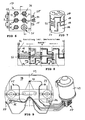
- the lubricating device initially comprises, as the core element, a structural unit 17 in which a lubricant pump 11 and a progressive distributor 13 are housed.
- the structural unit 17 essentially comprises an inner part 28 (cf., Fig. 2, which shows the assembly 17 in a partially open illustration for illustration purposes) and (see Figures 1 and 3) an outer part 27, in which the inner part 28 sealingly received is.
- On the outer part 27 are a plurality of lubricant dispensing points Provided 30 to 35, the funded via the lubricant pump 11 and distributed through the progressive distributor 13 to the lubricant dispensing points lubricant to him - to promote, for example via lines to respectively provided lubrication points.
- the inner part 28 is frictionally held in the outer part 27 and is preferably introduced by sealing in the outer part 27 that the outer part 27 is shrunk.
- a cover 49 terminates the assembly on one end side and is screwed by screws 50 to the outer part 27 of the assembly 17.
- the lubricant pump 11 has a pump element 12 which is mounted displaceably in a bore 51.
- This pump element 12 is driven by a motor 25 and a rotationally connected to the motor eccentric 26, wherein the eccentric 26 comprises a pump element 12 pressingly acting eccentric surface 52 and the eccentric 52 partially surrounding eccentric groove 53.
- the eccentric groove 53 engages a end arranged on the pump element 12 plate 54, so that the pump element 12 is acted upon by the eccentric 26 not only pushing, but also pulling.
- the pump element 12 is thus offset by the eccentric 26 in a reciprocating motion without the provision of other return elements, such as springs o.ä. would be necessary.
- the common assembly 17 of the lubricant pump 11 and progressive distributor 13 is connected directly or rigidly in the present embodiment without the interposition of flexible lines or hoses with a reservoir 43, from which the lubricant pump 11 takes the necessary lubricant to supply the lubrication points.
- the reservoir has a follower piston 45 mounted within the reservoir 43, which is acted upon by tension springs 46, 47, wherein the lubricant in the present embodiment, the tension springs 46, 47 surrounds and is pressurized by this, to the influx of lubricant into the To facilitate the lubricant pump 11.
- the reservoir also has a Filling connection 55, a vent pipe 56 and an overfill 57 on.
- the reservoir 43 can be filled with lubricant via the filling connection 55.
- a measuring transmission rod 58 is provided, which is designed to control the level of the lubricant in the reservoir 43 and / or to scan the number of revolutions of the eccentric 26.
- this transmission or scanning can also be realized in a common measuring transmission rod 58.
- the illustrated measuring transmission rod 58 is slightly linearly deflected by the follower piston 45 shortly before it reaches its end position in the direction of movement of the follower piston 45.
- This linear deflection can be detected via a mechanical and / or electromagnetically operating first scanning element 59, which is designed in particular as a light barrier.
- the deflection of the eccentric 26 is scanned by an eccentric scanning rod 60 formed substantially orthogonally to the measuring transmission rod 58, wherein the distal end of the eccentric sensing rod 60 remote from the measuring transmission rod 58 slides over the eccentric surface 52 during rotation of the eccentric 26, so that the measuring transmission rod 58 is set in torsional vibration.
- the torsional vibration of the Meßübertragungsstange 58 can be detected via a second sensing element 61, which is here also concretely designed as a light barrier, which detects the torsional vibration of the Meßübertragungsstange 58 via a non-rotatably mounted on the Meßübertragungsstange 58 sensing rod 62, ie on the passage of the sensing rod 62 by the Photocell trained second sensing element 61 can detect the number of pump strokes of the pump element 12 of the lubricant pump 11.
- the structural unit 17 is schematically illustrated in a first sectional view through the pump element 12.
- the pump element 12 is slidably mounted in a bore 51 of the inner part 28 as already mentioned.
- the bore 51 communicates with a lubricant inlet 44, via which lubricant can enter the structural unit 17 from a lubricant outlet 48 of the reservoir 43.
- the pump element 12 comprises a delivery piston 63 and a front end projecting beyond the inner part 28, on which the already mentioned plate 54 is arranged, which engages as the head of the pump element in the already mentioned eccentric groove 53.
- the progressive distributor 13 integrated in the assembly 17 comprises a plurality of, in the present embodiment (see Fig. 5) three metering pistons 14 to 16, which are constructed as shown in Fig. 4, namely two outer piston elements 65, 66 and an inner piston member 67th include. Between the central, inner piston element 67 and the outer piston elements 65, 66 a tapered region 68, 69 is provided, which serve for receiving or for transferring lubricant depending on the position of the metering between different channels of the progressive distributor 13.
- the various lines of the progressive distributor 13 are, as can be seen from the perspective view of the inner part 28 in Fig. 7, to a large part of the outer surface (lateral surface) of the inner part 28 forth as groove-shaped channels 18 to 22 formed, in particular milled, which greatly facilitates the production.
- the progression of the metering pistons 14 to 16, that is, the Um Kunststoffschema is clear from the settlement of FIG. 8.
- the volume of lubricant which is present at the front end of a metering piston is dispensed by displacement of the metering piston in the direction of a lubricant delivery point.
- FIGS. 4, 5 and 6 show a preferred embodiment of the lubricant dispensers 30 to 35 on the progressive distributor 13.
- the lubricant dispensing points 30 to 35 initially comprise bores 38, 39, 40, which are provided with an internally threaded portion into which either a closure screw 37 or a lubricating point connecting element 36 can be screwed.
- return passage 29 the plurality of bores 38, 39, 40, if necessary, all holes of the lubricant discharge points 30 to 35 can be connected to each other, is at a non-required lubricant discharge point, which is closed with a screw plug 37, the transferred from the dosing to this lubrication point lubricant transferred into the return channel 29 so that the dosing not blocked by accumulating lubricant, but can continue to advance.
- the lubricant to be dispensed at the respective lubricant dispensing point is therefore conveyed through the central opening 70, 71 of the bypass sleeve 41, 42, whereas Lubricant in the return channel 29 outside of the bypass sleeve within the bore 39 can flow past.
- Fig. 6 the assembly 17 is shown in a frontal view of the lubricant dispensing points 30 to 35, wherein, as shown in Fig. 5, the lubricant dispensing point is closed at the bottom right with a screw plug 37.
- the partially protruding from the assembly 17 pump element 12 can be driven with any pump drive 24, preferably with the interposition of an eccentric 26, wherein an electric, hydraulic, pneumatic or mechanical drive can be considered.
- the unit proposed here is very compact and universally applicable. In each case suitable drive modules can be used.
- a reservoir 43 can be adapted in size and shape as needed and preferably directly connected to form a total compact unit to the assembly 17, possibly also in the form of an interchangeable cartridge. Of course, it is also possible to connect a reservoir via flexible lines with the assembly 17.
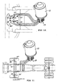
- FIGS. 9 to 11 Typical installation situations for the lubricating device according to the invention are illustrated in FIGS. 9 to 11.
- Fig. 9 the installation of the lubricating device according to the invention comprising a structural unit 17 and a directly connected thereto reservoir 43 for the supply of Lubrication points 72 to 77 of a fifth wheel 78 illustrated.
- the lubricating device according to the invention can either be attached directly to the fifth wheel 78 itself, for example in a frontal area 79 or in the immediate vicinity of the fifth wheel 79 on a vehicle.
- FIG. 10 illustrates an example of application of the lubricating device according to the invention for lubricating a truck trailer coupling 80.
- the truck trailer coupling 80 is supplied with lubricant by the lubrication device according to the invention, here via specifically six lubrication points 81 to 86.
- FIG. 11 another application example for the lubrication of multiple lubrication points 87 to 90 in the region of the axis 91 of a truck is illustrated, wherein the lubricating device according to the invention with the compact unit 17 decentralized, that can be mounted relatively close to the axis 91 of the vehicle.
Landscapes
- Engineering & Computer Science (AREA)
- Mechanical Engineering (AREA)
- General Engineering & Computer Science (AREA)
- Chemical & Material Sciences (AREA)
- Combustion & Propulsion (AREA)
- Transportation (AREA)
- Lubrication Of Internal Combustion Engines (AREA)
- Reciprocating Pumps (AREA)
- Fertilizing (AREA)
- General Details Of Gearings (AREA)
Description
- Die Erfindung betrifft eine Schmiereinrichtung zur Ausgabe von Schmierstoff aus einer Schmierstoffquelle an vorbestimmte Schmierstoffausgabestellen umfassend eine Schmierstoffpumpe mit einem verschieblich gelagerten Pumpenelement sowie einem Progressivverteiler mit einer Mehrzahl parallel zueinander gelagerter Dosierkolben nach dem Oberbegriff des Patentanspruchs 1.
- Derartige Schmiereinrichtungen sind aus dem Stand der Technik bekannt und werden beispielsweise zur Abschmierung einer Mehrzahl von Schmierstellen an einem Fahrzeug, wie einem Lastkraftwagen, an Baumaschinen oder auch in industriellen Anlagen eingesetzt.
- Die Aufgabe der vorliegenden Erfindung besteht ausgehen von den bekannten Schmiereinrichtungen darin, eine Schmiereinrichtung anzugeben, die wesentlich kompakter aufgebaut ist, so dass eine Anbringung auch in beengten Einbaulagen möglich wird.
- Diese Aufgabe wird mit einer Schmiereinrichtung nach den Merkmalen des Anspruches 1 gelöst. Ein Kerngedanke der vorliegenden Erfindung besteht darin, sowohl Progressivverteiler als auch Schmierstoffpumpe in einer ein Innenteil sowie ein Außenteil aufweisenden Baueinheit unterzubringen bzw. auszubilden und dabei sowohl die Dosierkolben als auch das Pumpenelement selbst gemeinsam im Innenteil unterzubringen bzw. zu lagern.
- Hierdurch wird ein äußerst kompakter Aufbau erreicht. Mit diesem kompakten Aufbau wird es nun möglich, räumlich dicht beieinanderliegende Schmierstellen, die sonst von einer räumlich oft erheblich weit beabstandeten Zentralschmieranlage versorgt werden mussten, lokal durch die erfindungsgemäße kompakte Schmiereinrichtung zu versorgen. Die erfindungsgemäße Schmiereinrichtung lässt sich durch ihren kompakten Aufbau auch in beengten Montageverhältnissen anbringen. Trotz des kompakten Aufbaus bleibt die zuverlässige Versorgung mit einer ausreichenden Menge an Schmierstoff gewährleistet.
- Darüber hinaus lassen sich einzelne zu schmierende Komponenten einer komplexeren Vorrichtung, wie beispielsweise die Sattelkupplung oder die Anhängerkupplung eines Lastkraftwagens autark, d.h., mit eigener Schmiereinrichtung schon herstellerseitig ausstatten, so dass diese Komponenten beim Einbau in die komplexere Vorrichtung bzw. beim Einbau in den Lastkraftwagen nicht erst aufwendig noch an eine Zentralschmieranlage angeschlossen werden müssen.
- In einer konkret bevorzugten Weiterbildung ist die Lagerung der Dosierkolben sowie des Pumpenelements in der gemeinsamen Baueinheit, konkret im Innenteil so ausgestaltet, dass sie parallel zueinander, insbesondere parallel zu einer Vorzugsachse des Grundkörpers verschieblich gelagert sind.
- In einer weiter bevorzugten Ausgestaltung weist das Innenteil eine im Wesentlichen zylindrische Grundform auf, was den kompakten Aufbau der gesamten Baueinheit weiter begünstigt.
- In einer besonders bevorzugten Ausgestaltung sind im Innenteil außenseitig nutförmige Kanäle eingeformt, die durch Einschieben des Innenteils in ein das Innenteil dichtend umgebendes Außenteil dichtend abgeschlossen werden. Hierdurch lassen sich ein Großteil der in einem Pumpenelement bzw. in einem Progressivverteiler notwendigen Schmierstoffkanäle in den Bereich der Mantelfläche des Innenteils verlegen, wo sie im Herstellungsprozess des Innenteils mit vergleichsweise geringem Aufwand ausgebildet werden können.
- Obwohl nach der Grundidee der vorliegenden Erfindung Progressivverteiler und Schmierstoffpumpe zu einer kompakten gemeinsamen Baueinheit zusammengefasst sind, welche das wesentliche Kernstück der erfindungsgemäßen Schmiereinrichtung definiert, kann diese Schmiereinrichtung optional auch weitere Komponenten, nämlich einen Pumpenantrieb und/oder ein Reservoir als Schmierstoffquelle umfassen. Dabei kann der Pumpenantrieb beispielsweise einen Motor zur Erzeugung einer Drehbewegung und einen von der Drehbewegung des Motors angetriebenen Exzenter umfassen, der das Pumpenelement antreibt. Besonders bevorzugt wird eine Ausgestaltung, in der der Exzenter eine Zwangsführung umfasst, so dass das Pumpenelement vom Exzenter nicht nur drückend, sondern auch ziehend beaufschlagt wird. Rückholelemente, wie beispielsweise Federn o.ä., die das Pumpenelement in Anlage an eine Exzenterfläche halten, können dadurch vermieden werden. Auch dies begünstigt den einfacheren und gleichzeitig kompakteren Aufbau der gesamten Anordnung.
- Nach einer weiteren bevorzugten Ausgestaltung der vorliegenden Erfindung ist innerhalb des Progressivverteilers, vorzugsweise innerhalb der Baueinheit im Außengehäuse mindestens ein Rücklaufkanal zur Rückführung von Schmierstoff im Fall einer blockierten Schmierstoffausgabestelle vorgesehen. Dieser Rücklaufkanal kann beispielsweise Schmierstoff an die Schmierstoffquelle, insbesondere in ein als Schmierstoffquelle dienendes Reservoir oder an eine andere Sammelstelle führen. Ist ein als Schmierstoffquelle dienendes Reservoir unmittelbar an die Baueinheit von Schmierstoffpumpe und Progressivverteiler angeschlossen, was weiter unten noch näher erläutert wird, so kann der Rücklaufkanal der Baueinheit zurückgeführten Schmierstoff ebenfalls unmittelbar an das als Schmierstoffquelle dienendes Reservoir ohne Zwischenschaltung gesonderter Leitungen übergeben.
- Nach einem weiter bevorzugten Ausgestaltung der vorliegenden Erfindung ist mindestens ein Rücklaufkanal als Rückführung für mehrere Schmierstoffausgabestellen, vorzugsweise ein ggf. verzweigter gemeinsamer Rücklaufkanal für alle Schmierstoffausgabestellen vorgesehen. Obwohl es prinzipiell denkbar wäre, für jede Schmierstoffabgabestelle einen eigenen Rücklaufkanal, der bedarfsweise wirksam werden kann, vorzusehen, wird es als wesentlich vorteilhafter angesehen, wenn ein einziger ggf. verzweigter Rücklaufkanal für alle Schmierstoffausgabestellen gemeinsam vorgesehen ist.
- In einer konkret bevorzugten Ausgestaltung zur Ausbildung des Rücklaufkanals sind die Schmierstoffausgabelstellen jeweils am Außenteil der Baueinheit vorgesehen und umfassen dabei jeweils eine Bohrung, in der entweder ein Schmierstellenanschlusselement oder eine Verschlussschraube fluiddicht eingesetzt, insbesondere eingeschraubt werden kann, wobei ein gemeinsamer Rücklaufkanal mindestens einen Teil der Bohrungen miteinander verbindet und wobei bei eingesetztem Schmierstellenanschlusselement eine Bypasshülse dafür sorgt, dass der Rücklauf gegenüber einer vorgeschalteten bzw. nachgeschalteten Bohrung (Schmierstoffausgabestelle) nicht blockiert ist und auch kein zur Ausgabe über das Schmierstellenanschlusselement vorgesehener Schmierstoff in den Rücklaufkanal eintreten kann.
- Diese Ausgestaltung ermöglicht eine quasi automatische Anbindung der Schmierstoffausgabestelle an den Rücklaufkanal, für den Fall, dass die Schmierstoffausgabestelle nicht benötigt und mit einer Verschlussschraube verschlossen wird. Bekanntermaßen würde ohne das Vorsehen eines solchen Rücklaufkanals ein Verschließen der Schmierstoffausgabestelle dazu führen, dass der gesamte Progressivverteiler blockiert wird und damit eine Verteilung von Schmierstoff an die übrigen Schmierstellen verunmöglicht wird.
- In einer besonders zweckmäßigen Ausgestaltung kann die Bypasshülse jeweils am stirnseitigen Ende des Schmierstellenanschlusselements fest angeordnet sein, so dass automatisch dafür gesorgt ist, dass kein zur Ausgabe über das Schmierstellenanschlusselement vorgesehener Schmierstoff in den Rücklaufkanal eintreten kann.
- Wie bereits erwähnt, kann die Schmiereinrichtung weiterhin ein Reservoir umfassen, welches dauerhaft mit der Baueinheit von Progressivverteiler und Pumpenelement verbunden ist, insbesondere unmittelbar und insbesondere starr daran angeschlossen ist. Insofern kann in einer bevorzugten Ausgestaltung der Schmierstoffausgang des Reservoirs direkt mit einem Schmierstoffeintritt der Baueinheit starr verbunden werden.
- In einer weiter bevorzugten Ausgestaltung umfasst das Reservoir einen Folgekolben, der über Zugfedern den Schmierstoff mit Druck beaufschlagt. Während die Beaufschlagung des Schmierstoffs im Reservoir durch Federn an sich bekannt ist, erfolgt dies nach dem Stand der Technik meist durch Druckfedern, welche an der dem Schmierstoff abgewandten Seite des Folgekolbens angreifen. Die hier vorgeschlagenen Zugfedern sind im Reservoir bevorzugtermaßen innerhalb der mit Schmierstoff gefüllten Kammer vorgesehen, so dass ein noch kompakterer Aufbau der gesamten Anordnung erzielbar ist.
- Weiterhin kann mindestens eine optische und/oder mechanische Messeinrichtung zur Überwachung der Hübe des Pumpenelements und/oder des Füllstandes des Reservoirs vorgesehen sein. In einer konkret bevorzugten Ausgestaltung werden sowohl die Hübe des Pumpenelements als auch der Füllstand des Reservoirs zunächst mechanisch abgenommen und über eine gemeinsame Übertragungsstange an einen optischen Messabgriff übermittelt. Konkret kann die gemeinsame Übertragungsstange beispielsweise durch den Exzenter in Drehschwingung versetzt werden und unabhängig davon bei Annäherung des Folgekolbens des Reservoirs an seine Minimalstellung in eine lineare Auslenkung versetzt werden.
- Wegen ihres kompakten Aufbaus eignet sich die erfindungsgemäße Schmiereinrichtung auch zum Einbau unter beengten Platzverhältnissen. Hierdurch wird die Möglichkeit geschaffen, die Schmierstoffpumpe einer Schmiereinrichtung nicht nur an ggf. relativ weit von den eigentlichen Schmierstellen entfernten Orten, sondern auch in beengter Einbaulage relativ nah zu den jeweils zu versorgenden Schmierstellen anzuordnen. Konkrete Anwendungsfälle für die erfindungsgemäße Schmiereinrichtung kann der Einbau an oder in Nähe einer Sattelkupplung zur Versorgung der Schmierstellen einer Sattelkupplung sein. Ebenso denkbar ist der Anbau an oder in Nähe einer Anhängerkupplung zur Versorgung der Schmierstellen einer Anhängerkupplung. Weiterhin kann die erfindungsgemäße Schmiereinrichtung in der Nähe der Achse eines Lastkraftwagens angeordnet sein und dort die Schmierstellen dieser sowie ggf. unmittelbar benachbarter Achsen abschmieren. Es versteht sich von selbst, dass die vorstehend genannten Anwendungsbeispiele rein illustrativ sind und die Anwendungsgebiete der neuen, kompakten Schmiereinrichtung keineswegs beschränken, sondern zahlreiche weitere Anwendungsfälle denkbar sind.
- Entsprechend kann die erfindungsgemäße Schmiereinrichtung bevorzugtermaßen auch in Einbausituationen zur Anwendung kommen, in der eine Mehrzahl räumlich dicht beeinanderliegender Schmierstellen vorliegen. Besonders bevorzugte Einbausituationen sind solche, in denen die zu versorgenden Schmierstellen jeweils nicht mehr als 3,5 Meter auseinanderliegen. Die Erfindung wird nachstehend auch hinsichtlich weiterer Merkmale und Vorteile anhand der Beschreibung von Ausführungsbeispielen und unter Bezugnahme auf die nachstehenden Zeichnungen näher erläutert. Hierbei zeigen:
- Fig. 1
- eine konkrete Ausführungsform der erfindungsgemäßen Schmiereinrichtung mit Pumpenantrieb und Reservoir in einer schematischen Perspektivansicht,
- Fig. 2
- die Schmiereinrichtung nach Fig. 1 in einer modifizierten Perspektivansicht,
- Fig. 3
- die Schmiereinrichtung nach den Figuren 1 und 2 in einer nochmals modifizierten Perspektivansicht,
- Fig. 4
- eine Schnittansicht durch eine konkrete Ausführungsform der erfindungsgemäßen Baueinheit,
- Fig. 5
- eine zur Schnittansicht nach Fig. 4 orthogonale Schnittansicht durch die erfindungsgemäße Baueinheit,
- Fig. 6
- eine Draufsicht auf die Baueinheit nach Fig. 4 bzw. Fig. 5,
- Fig. 7
- eine perspektivische Ansicht des Innenteils der Baueinheit nach den Figuren 4 bis 6,
- Fig. 8
- eine schematische Abwicklung des Innenteils nach Fig. 7 mit Andeutung des Umsteuerschemas der Dosierkolben,
- Fig. 9
- eine modifizierte Ausführungsform der erfindungsgemäßen Schmiereinrichtung in einer Anschlusssituation an einer Sattelkupplung,
- Fig. 10
- die Ausführungsform der erfindungsgemäßen Schmiereinrichtung nach Fig. 9 in einer Anschlusssituation an einer LKW-Anhängerkupplung,
- Fig. 11
- die Schmiereinrichtung nach den Figuren 9 und 10 in einer Anschlusssituation an der Achse eines LKW.
- In den Figuren 1 bis 3 ist eine konkrete Ausführungsform der erfindungsgemäßen Schmiereinrichtung mit Pumpenantrieb und Reservoir in einer schematischen Perspektivansicht dargestellt. Die Schmiereinrichtung umfasst zunächst als Kernelement eine Baueinheit 17, in der eine Schmierstoffpumpe 11 sowie ein Progressivverteiler 13 untergebracht ist. Die Baueinheit 17 umfasst dabei im Wesentlichen (vgl. Fig. 2, welche die Baueinheit 17 in einer zu Illustrationszwecken teilweise geöffneten Darstellung zeigt) ein Innenteil 28 sowie (vgl. Figuren 1 und 3) ein Außenteil 27, in dem das Innenteil 28 dichtend aufgenommen ist. Am Außenteil 27 sind eine Mehrzahl von Schmierstoffausgabestellen 30 bis 35 vorgesehen, die über die Schmierstoffpumpe 11 geförderten und über den Progressivverteiler 13 auf die Schmierstoffausgabestellen verteilten Schmierstoff ausgeben, um ihn - beispielsweise über Leitungen an jeweils vorgesehene Schmierstellen zu fördern. Das Innenteil 28 ist reibschlüssig im Außenteil 27 gehalten und wird bevorzugtermaßen dadurch dichtend in das Außenteil 27 eingebracht, dass das Außenteil 27 aufgeschrumpft wird. Ein Deckel 49 schließt die Baueinheit an einer Stirnseite endseitig ab und ist über Schrauben 50 mit den Außenteil 27 der Baueinheit 17 verschraubt.
- Die Schmierstoffpumpe 11 weist ein Pumpenelement 12 auf, welches in einer Bohrung 51 verschieblich gelagert ist. Dieses Pumpenelement 12 wird über einen Motor 25 und einen drehschlüssig mit dem Motor verbundenen Exzenter 26 angetrieben, wobei der Exzenter 26 eine das Pumpenelement 12 drückend beaufschlagende Exzenterfläche 52 sowie eine die Exzenterfläche 52 teilweise umgebende Exzenternut 53 umfasst. In die Exzenternut 53 greift ein endseitig am Pumpenelement 12 angeordneter Teller 54 ein, so dass das Pumpenelement 12 durch den Exzenter 26 nicht nur drückend, sondern auch ziehend beaufschlagt wird. Insgesamt wird das Pumpenelement 12 damit durch den Exzenter 26 in eine Hin- und Herbewegung versetzt, ohne dass das Vorsehen weiterer Rückholelemente, wie beispielsweise Federn o.ä. notwendig wäre.
- Die gemeinsame Baueinheit 17 aus Schmierstoffpumpe 11 und Progressivverteiler 13 ist bei der vorliegenden Ausführungsform ohne Zwischenschaltung flexibler Leitungen oder Schläuche direkt bzw. starr mit einem Reservoir 43 verbunden, aus dem die Schmierstoffpumpe 11 den zur Versorgung der Schmierstellen notwendigen Schmierstoff entnimmt. Das Reservoir weist einen innerhalb des Reservoirs 43 gelagerten Folgekolben 45 auf, der über Zugfedern 46, 47 beaufschlagt wird, wobei der Schmierstoff bei der vorliegenden Ausführungsform die Zugfedern 46, 47 umgibt und durch diese mit Druck beaufschlagt wird, um das Einströmen von Schmierstoff in die Schmierstoffpumpe 11 zu erleichtern. Das Reservoir weist weiterhin einen Befüllanschluss 55, einen Entlüftungsstutzen 56 sowie eine Überfüllsicherung 57 auf. Das Reservoir 43 kann über den Befüllanschluss 55 mit Schmierstoff befüllt werden. Wenn der maximale Füllstand erreicht ist, wird zu viel eingefüllter Schmierstoff über die Überfüllsicherung 57 nach außen abgeführt, so dass eine Überbefüllung vermeidbar ist, bzw. der maximale Füllstand erkennbar ist. Alternativ ist es auch denkbar, das Reservoir als Austauschkartusche auszubilden, so dass ein Nachbefüllen des Reservoirs 43 am Einsatzort der Schmiereinrichtung nicht notwendig ist.
- Schließlich ist nach einem besonderen Aspekt der vorliegenden Erfindung eine Messübertragungsstange 58 vorgesehen, die zur Kontrolle des Füllstandes des Schmierstoffs im Reservoir 43 und/oder zur Abtastung der Umdrehungszahl des Exzenters 26 ausgebildet ist. In einer konkret bevorzugten Ausgestaltung kann, wie anhand der Figuren 1 bis 3 veranschaulicht, diese Übertragung bzw. Abtastung auch in einer gemeinsamen Messübertragungsstange 58 verwirklicht sein.
- Konkret wird die dargestellte Messübertragungsstange 58 durch den Folgekolben 45 kurz bevor dieser seine Endstellung erreicht in Bewegungsrichtung des Folgekolbens 45 leicht linear ausgelenkt. Diese lineare Auslenkung lässt sich über ein mechanisches und/oder elektromagnetisch arbeitendes erstes Abtastelement 59, das insbesondere als Lichtschranke ausgebildet ist, erfassen. Gleichzeitig wird die Auslenkung des Exzenters 26 durch eine im Wesentlichen orthogonal an die Messübertragungsstange 58 angeformte Exzenter-Abtaststange 60 abgetastet, wobei das distale, der Messübertragungsstange 58 abgewandte Ende der Exzenter-Abtaststange 60 bei Rotation des Exzenters 26 über die Exzenterfläche 52 gleitet, so dass die Messübertragungsstange 58 in Drehschwingung versetzt wird. Die Drehschwingung der Messübertragungsstange 58 ist über ein zweites Abtastelement 61 erfassbar, das hier konkret ebenfalls als Lichtschranke ausgebildet ist, welche über ein drehfest an der Messübertragungsstange 58 angebrachte Abtaststange 62 die Drehschwingung der Messübertragungsstange 58 erfasst, d.h. über den Durchgang der Abtaststange 62 durch das als Lichtschranke ausgebildetes zweites Abtastelement 61 die Zahl der Pumpenhübe des Pumpenelements 12 der Schmierstoffpumpe 11 erfassen kann.
- In Fig. 4 ist die Baueinheit 17 in einer ersten Schnittansicht durch das Pumpenelement 12 schematisch veranschaulicht. Das Pumpenelement 12 ist wie bereits erwähnt verschieblich in einer Bohrung 51 des Innenteils 28 gelagert. Die Bohrung 51 kommuniziert bei herausgezogenem Pumpenelement 12 bzw. in der nach einem Saughub herausgezogenen Stellung mit einem Schmierstoffeintritt 44, über den Schmierstoff aus einem Schmierstoffausgang 48 des Reservoirs 43 in die Baueinheit 17 eintreten kann. Das Pumpenelement 12 umfasst einen Förderkolben 63 sowie ein über das Innenteil 28 herausragendes stirnseitiges Ende, an dem der bereits erwähnte Teller 54 angeordnet ist, der als Kopf des Pumpenelements in die bereits erwähnte Exzenternut 53 eingreift.
- Bei einem anschließenden Druckhub, d.h. Verschieben des Pumpenelements 12 mit dem Förderkolben 63 in das Innenteil 28 hinein, wird der in der Bohrung 51 aufgenommene Schmierstoff in Richtung auf ein Rückschlagventil 64 gepresst. Das Rückschlagventil 64 arbeitet so, dass es Schmierstoff in einen Schmierstoffzuführungskanal 92 des Progressivverteilers überführt, jedoch einen Rücklauf aus dem Schmierstoffzuführungskanal 92 zurück in das Pumpenelement 12 verhindert. Der in der Baueinheit 17 integrierte Progressivverteiler 13 umfasst mehrere, bei der vorliegenden Ausführungsform (vgl. Fig. 5) drei Dosierkolben 14 bis 16, die wie aus Fig. 4 ersichtlich aufgebaut sind, nämlich zwei äußere Kolbenelemente 65, 66 sowie ein inneres Kolbenelement 67 umfassen. Zwischen dem zentralen, inneren Kolbenelement 67 und den äußeren Kolbenelementen 65, 66 ist jeweils ein verjüngter Bereich 68, 69 vorgesehen, die zur Aufnahme bzw. zur Überführung von Schmierstoff je nach Position des Dosierkolbens zwischen verschiedenen Kanälen des Progressivverteilers 13 dienen.
- Die verschiedenen Leitungen des Progressivverteilers 13 sind, wie aus der perspektivischen Darstellung des Innenteils 28 in Fig. 7 ersichtlich wird, zu einem großen Teil von der äußeren Fläche (Mantelfläche) des Innenteils 28 her als nutförmige Kanäle 18 bis 22 eingeformt, insbesondere eingefräst, was die Herstellung erheblich erleichtert. Die Fortschaltung der Dosierkolben 14 bis 16, also das Umsteuerschema wird aus der Abwicklung nach Fig. 8 deutlich. Durch die Verschiebebewegung der Dosierkolben 14 bis 16 wird jeweils das von einem Dosierkolben an seinem stirnseitigen Ende anstehende Volumen von Schmierstoff durch Verschiebung des Dosierkolbens in Richtung auf eine Schmierstoffausgabestelle ausgegeben, wie an sich bekannt.
- Aus den Figuren 4, 5 und 6 wird eine bevorzugte Ausgestaltung der Schmierstoffausgabestellen 30 bis 35 am Progressivverteiler 13 ersichtlich. Die Schmierstoffausgabestellen 30 bis 35 umfassen zunächst Bohrungen 38, 39, 40, die mit einem Innengewindeabschnitt versehen sind, in die entweder eine Verschlussschraube 37 oder ein Schmierstellenanschlusselement 36 einschraubbar ist. Über einen nach einem besonderen Aspekt der Erfindung vorgesehenen Rücklaufkanal 29, der mehrere Bohrungen 38, 39, 40 ggf. auch alle Bohrungen der Schmierstoffausgabestellen 30 bis 35 miteinander verbinden kann, wird bei einer nicht benötigten Schmierstoffausgabestelle, die mit einer Verschlussschraube 37 verschlossen ist, der von den Dosierkolben an diese Schmierstelle ausgegebene Schmierstoff in den Rücklaufkanal 29 überführt, so dass die Dosierkolben nicht durch sich aufstauenden Schmierstoff blockieren, sondern weiter fortschalten können. Eine Bypasshülse 41, 42 mit einer zentralen Öffnung 70, 71, die koaxial zum zugeordneten Schmierstellenanschlusselement 36 ausgerichtet ist, bewirkt, dass im Rücklaufkanal 29 transportierter Schmierstoff über die Bohrung 39 der betreffenden Schmierstoffausgabestelle 31 geleitet werden kann, ohne dass eine Fluidverbindung zu dem über das Schmierstellenanschlusselement 36 ausgegebenen Schmierstoff besteht. Der an der betreffenden Schmierstoffausgabestelle abzugebende Schmierstoff wird daher durch die zentrale Öffnung 70, 71 der Bypasshülse 41, 42 gefördert, wohingegen Schmierstoff im Rücklaufkanal 29 außen an der Bypasshülse innerhalb der Bohrung 39 vorbeifließen kann.
- Diese Situation wird aus der Darstellung in Fig. 5 verständlich, in der in der untersten Schmierstoffausgabestelle eine Verschlussschraube 37 eingesetzt ist, so dass dort ausgegebener Schmierstoff über den Rücklaufkanal 29 zurück an das Reservoir 43 geführt werden kann, das nach einem besonders bevorzugten Aspekt der vorliegenden Erfindung starr an die Baueinheit 17 unmittelbar angeschlossen sein kann. In einer bevorzugten Ausgestaltung kann die Bypasshülse 41, 42 am in Einführrichtung vorderen Ende des Schmierstellenanschlusselements verliersicher angebracht, insbesondere einstückig angeformt sein.
- In Fig. 6 ist die Baueinheit 17 in einer Ansicht frontal auf die Schmierstoffausgabestellen 30 bis 35 dargestellt, wobei entsprechend der Darstellung in Fig. 5 die Schmierstoffausgabestelle rechts unten mit einer Verschlussschraube 37 verschlossen ist. Das teilweise aus der Baueinheit 17 herausragende Pumpenelement 12 kann mit einem beliebigen Pumpenantrieb 24, vorzugsweise unter Zwischenschaltung eines Exzenters 26, angetrieben werden, wobei ein elektrischer, hydraulischer, pneumatischer oder mechanischer Antrieb in Betracht kommen kann. Insgesamt ist die hier vorgeschlagene Baueinheit sehr kompakt und universell einsetzbar. Es können jeweils geeignete Antriebsmodule angesetzt werden. Ein Reservoir 43 kann je nach Bedarf in Größe und Gestalt angepasst werden und bevorzugtermaßen direkt zur Ausbildung einer insgesamt kompakten Einheit an die Baueinheit 17, ggf. auch in Gestalt einer Wechselkartusche, angeschlossen werden. Selbstverständlich ist es aber auch möglich, ein Reservoir über flexible Leitungen mit der Baueinheit 17 zu verbinden.
- Typische Einbausituationen für die erfindungsgemäße Schmiereinrichtung sind in den Figuren 9 bis 11 veranschaulicht. In Fig. 9 ist die Installation der erfindungsgemäßen Schmiereinrichtung umfassend eine Baueinheit 17 sowie ein unmittelbar hieran angeschlossenes Reservoir 43 zur Versorgung der Schmierstellen 72 bis 77 einer Sattelkupplung 78 veranschaulicht. Die erfindungsgemäße Schmiereinrichtung kann entweder unmittelbar an der Sattelkupplung 78 selbst, beispielsweise in einem frontalen Bereich 79 oder in unmittelbarer Nähe zur Sattelkupplung 79 an einem Fahrzeug befestigt werden.
- In Fig. 10 ist ein Anwendungsbeispiel der erfindungsgemäßen Schmiereinrichtung zur Abschmierung einer LKW-Anhängerkupplung 80 veranschaulicht. Die LKW-Anhängerkupplung 80 wird durch die erfindungsgemäße Schmiereinrichtung, hier über konkret sechs Schmierstellen 81 bis 86 mit Schmierstoff versorgt.
- In Fig. 11 ist ein weiteres Anwendungsbeispiel zur Abschmierung mehrerer Schmierstellen 87 bis 90 im Bereich der Achse 91 eines LKW veranschaulicht, wobei die erfindungsgemäße Schmiereinrichtung mit der kompakten Baueinheit 17 dezentral, d.h. relativ nahe an der Achse 91 des Fahrzeugs befestigt werden kann.
-
- 11
- Schmierstoffpumpe
- 12
- Pumpenelement
- 13
- Progressivverteiler
- 14 bis 16
- Dosierkolben
- 17
- Baueinheit
- 18 bis 22
- nutförmige Kanäle
- 24
- Pumpenantrieb
- 25
- Motor
- 26
- Exzenter
- 27
- Außenteil
- 28
- Innenteil
- 29
- Rücklaufkanal
- 30 bis 35
- Schmierstoffausgabestellen
- 36
- Schmierstellenanschlusselement
- 37
- Verschlussschraube
- 38, 39, 40
- Bohrungen (Schmierstoffausgabestellen)
- 41, 42
- Bypasshülse
- 43
- Reservoir
- 44
- Schmierstoffeintritt (Baueinheit)
- 45
- Folgekolben
- 46, 47
- Zugfedern
- 48
- Schmierstoffausgang (Reservoir)
- 49
- Deckel
- 50
- Schrauben (Deckel)
- 51
- Bohrung (Pumpenelement)
- 52
- Exzenterfläche
- 53
- Exzenternut
- 54
- Teller
- 55
- Befüllanschluss
- 56
- Entlüftungsstutzen
- 57
- Überfüllsicherung
- 58
- Messübertragungsstange
- 59
- erstes Abtastelement
- 60
- Exzenter-Abtaststange
- 61
- zweites Abtastelement
- 62
- Abtaststange
- 63
- Förderkolben
- 64
- Rückschlagventil
- 65, 66
- äußere Kolbenelemente
- 67
- inneres Kolbenelement
- 68, 69
- verjüngter Bereich
- 70, 71
- zentrale Öffnung (Bypasshülse)
- 72 bis 77
- Schmierstellen
- 78
- Sattelkupplung
- 79
- frontaler Bereich
- 80
- LKW-Anhängerkupplung
- 81 bis 86
- Schmierstellen
- 87 bis 90
- Schmierstellen
- 91
- Achse
- 92
- Schmierstoffzuführungskanal
Claims (13)
- Schmiereinrichtung zur Ausgabe von Schmierstoff aus einer Schmierstoffquelle an vorbestimmte Schmierstoffausgabestellen, umfassend:eine Schmierstoffpumpe (11) mit einem verschieblich gelagerten Pumpenelement (12) sowie einem Progressivverteiler (13) mit einer Mehrzahl parallel zueinander gelagerter Dosierkolben (14, 15, 16),dadurch gekennzeichnet,
dass Progressivverteiler (13) und Schmierstoffpumpe (11) in einer ein Innenteil (28) sowie ein Außenteil (27) umfassenden Baueinheit (17) ausgebildet sind, und
dass die Dosierkolben (14, 15, 16) und das Pumpenelement (12) gemeinsam im Innenteil (28) untergebracht sind. - Schmiereinrichtung nach Anspruch 1,
dadurch gekennzeichnet, dass die Dosierkolben (14, 15, 16) und das Pumpenelement (12) jeweils parallel zueinander, insbesondere parallel zu einer Vorzugsachse des Innenteils (28), gelagert sind. - Schmiereinrichtung nach Anspruch 1 oder 2,
dadurch gekennzeichnet,
dass das Innenteil (28) eine im Wesentlichen zylindrische Grundform aufweist. - Schmiereinrichtung nach einem der Ansprüche 1 bis 3,
dadurch gekennzeichnet,
dass im Innenteil (28) außenseitig nutförmige Kanäle (18 bis 23) eingeformt sind, die durch Einschieben des Innenteils (28) in das das Innenteil (28) dichtend umgebende Außenteil (27) zur Außenseite dichtend abgeschlossen werden. - Schmiereinrichtung nach einem der Ansprüche 1 bis 4,
dadurch gekennzeichnet,
dass die Schmiereinrichtung weiterhin einen Pumpenantrieb (24) umfasst, wobei der Pumpenantrieb (24), einen Motor (25) zur Erzeugung einer Drehbewegung und einen von der Drehbewegung des Motors (25) angetriebenen Exzenter (26) aufweist, der das Pumpenelement (12) antreibt. - Schmiereinrichtung nach einem der Ansprüche 1 bis 5,
dadurch gekennzeichnet,
dass innerhalb des Progressivverteilers (13), vorzugsweise der Baueinheit (17), insbesondere im Außenteil (27), mindestens ein Rücklaufkanal (29) zur Rückführung von Schmierstoff im Fall einer blockierten Schmierstoffausgabestelle (30 bis 35) vorgesehen ist. - Schmiereinrichtung nach Anspruch 6,
dadurch gekennzeichnet,
dass mindestens ein Rücklaufkanal (29) eine Rückführung für mehrere Schmierstoffausgabenstellen (30 bis 35) definiert. - Schmiereinrichtung nach einem der Ansprüche 1 bis 7,
dadurch gekennzeichnet,
dass die Schmierstoffausgabestellen (30 bis 35) jeweils am Außenteil der Baueinheit (17) vorgesehen sind und eine Bohrung (38; 39; 40) umfassen, in der entweder ein Schmierstellenanschlusselement (36) oder eine Verschlussschraube (37) fluiddicht eingesetzt, insbesondere eingeschraubt werden kann,
wobei ein gemeinsamer Rücklaufkanal (29) mindestens einen Teil der Bohrungen (38; 39; 40) miteinander verbindet und wobei bei eingesetztem Schmierstellenanschlusselement (36) eine Bypasshülse (41; 42) dafür sorgt, dass der Rücklaufkanal (29) gegenüber einer vorgeschalteten bzw. nachgeschalteten Bohrung (38; 39; 40) nicht blockiert ist und auch kein zur Ausgabe über das Schmierstellenanschlusselement (36) vorgesehener Schmierstoff in den Rücklaufkanal (29) eintreten kann. - Schmiereinrichtung nach einem der Ansprüche 1 bis 8,
dadurch gekennzeichnet, dass die Schmiereinrichtung weiterhin ein Reservoir (43) umfasst, welches dauerhaft mit der Baueinheit (17) aus Progressivverteiler (13) und Pumpenelement (12) verbunden ist. - Schmiereinrichtung nach Anspruch 9,
dadurch gekennzeichnet,
dass ein Schmierstoffausgang (48) des Reservoirs (43) direkt mit einem Schmiermitteleintritt (44) der Baueinheit (17) aus Progressivverteiler (13) und Pumpenelement (12) starr verbunden ist. - Schmiereinrichtung nach Anspruch 9 oder 10,
dadurch gekennzeichnet,
dass das Reservoir (43) einen Folgekolben (45) aufweist, der über Zugfedern (46, 47) den Schmierstoff mit Druck beaufschlagt. - Schmiereinrichtung nach einem der vorhergehenden Ansprüche,
dadurch gekennzeichnet,
dass eine optische und/oder mechanische Messeinrichtung zur Überwachung der Hübe des Pumpenelements (12) und/oder des Füllstandes des Reservoirs (43) vorgesehen ist. - Schmiereinrichtung nach einem der Ansprüche 1 bis 12, zur Verwendung zur Schmierung einer Sattelkupplung oder zur Abschmierung einer oder mehreren dicht beabstandeten Achsen eines Fahrzeugs zugeordneten Schmierstellen oder zur Abschmierung einer Anhängerkupplung.
Priority Applications (5)
| Application Number | Priority Date | Filing Date | Title |
|---|---|---|---|
| PL05011204T PL1726868T3 (pl) | 2005-05-24 | 2005-05-24 | Kompaktowe urządzenie smarownicze wyposażone w pompę smarowniczą i w progresywny rozdzielacz |
| DE502005001430T DE502005001430D1 (de) | 2005-05-24 | 2005-05-24 | Kompakte Schmiereinrichtung mit einer Schmierstoffpumpe und einem Progressivverteiler |
| EP05011204A EP1726868B1 (de) | 2005-05-24 | 2005-05-24 | Kompakte Schmiereinrichtung mit einer Schmierstoffpumpe und einem Progressivverteiler |
| AT05011204T ATE372483T1 (de) | 2005-05-24 | 2005-05-24 | Kompakte schmiereinrichtung mit einer schmierstoffpumpe und einem progressivverteiler |
| ES05011204T ES2293420T3 (es) | 2005-05-24 | 2005-05-24 | Dispositivo de lubricacion compacto con una bomba de lubricante y un distribuidor progresivo. |
Applications Claiming Priority (1)
| Application Number | Priority Date | Filing Date | Title |
|---|---|---|---|
| EP05011204A EP1726868B1 (de) | 2005-05-24 | 2005-05-24 | Kompakte Schmiereinrichtung mit einer Schmierstoffpumpe und einem Progressivverteiler |
Publications (2)
| Publication Number | Publication Date |
|---|---|
| EP1726868A1 EP1726868A1 (de) | 2006-11-29 |
| EP1726868B1 true EP1726868B1 (de) | 2007-09-05 |
Family
ID=34936866
Family Applications (1)
| Application Number | Title | Priority Date | Filing Date |
|---|---|---|---|
| EP05011204A Not-in-force EP1726868B1 (de) | 2005-05-24 | 2005-05-24 | Kompakte Schmiereinrichtung mit einer Schmierstoffpumpe und einem Progressivverteiler |
Country Status (5)
| Country | Link |
|---|---|
| EP (1) | EP1726868B1 (de) |
| AT (1) | ATE372483T1 (de) |
| DE (1) | DE502005001430D1 (de) |
| ES (1) | ES2293420T3 (de) |
| PL (1) | PL1726868T3 (de) |
Families Citing this family (2)
| Publication number | Priority date | Publication date | Assignee | Title |
|---|---|---|---|---|
| EP1921326A1 (de) * | 2006-08-25 | 2008-05-14 | Wärtsilä Schweiz AG | Versorgungseinheit für Druckfluid |
| DE102019106531A1 (de) | 2019-03-14 | 2020-09-17 | Baier & Köppel GmbH & Co. KG | Schmierstoffpumpe mit automatisch ankoppelnder Pumpeinheit und Verfahren zum Ankoppeln einer Pumpeinheit an eine Schmierstoffpumpe |
Family Cites Families (3)
| Publication number | Priority date | Publication date | Assignee | Title |
|---|---|---|---|---|
| US4632648A (en) * | 1985-06-24 | 1986-12-30 | Goyne Thomas S | Grease pumps |
| US6244387B1 (en) * | 1999-10-12 | 2001-06-12 | Lincoln Gmbh | Lubricant supply device |
| DE20019186U1 (de) * | 2000-11-10 | 2001-01-11 | Baier & Koeppel Gmbh & Co | Fahrzeuggebundene Zentralschmieranlage |
-
2005
- 2005-05-24 PL PL05011204T patent/PL1726868T3/pl unknown
- 2005-05-24 DE DE502005001430T patent/DE502005001430D1/de active Active
- 2005-05-24 EP EP05011204A patent/EP1726868B1/de not_active Not-in-force
- 2005-05-24 ES ES05011204T patent/ES2293420T3/es active Active
- 2005-05-24 AT AT05011204T patent/ATE372483T1/de active
Non-Patent Citations (1)
| Title |
|---|
| None * |
Also Published As
| Publication number | Publication date |
|---|---|
| EP1726868A1 (de) | 2006-11-29 |
| DE502005001430D1 (de) | 2007-10-18 |
| PL1726868T3 (pl) | 2008-01-31 |
| ES2293420T3 (es) | 2008-03-16 |
| ATE372483T1 (de) | 2007-09-15 |
Similar Documents
| Publication | Publication Date | Title |
|---|---|---|
| EP1943452B1 (de) | Kolbenanordnung, insbesondere für zumessventile | |
| EP2024140B1 (de) | Selbsttätige schmierpumpe mit doppelt wirkendem antriebskolben | |
| EP2053300B1 (de) | Einleitungsverteiler | |
| EP2084451B1 (de) | Schmiermittelverteiler | |
| DE202008007080U1 (de) | Schmierstoffverteileranlage | |
| EP1631767B1 (de) | Verteilerelement für schmieranlagen | |
| EP1798464B1 (de) | Schmierstoffpumpe | |
| EP3810463A1 (de) | Elektronisch geregeltes hydraulisches reinigungssystem | |
| EP1726868B1 (de) | Kompakte Schmiereinrichtung mit einer Schmierstoffpumpe und einem Progressivverteiler | |
| DE1528582A1 (de) | Pumpe | |
| EP1626225B1 (de) | Einrichtung zur Zuführung von Schmierstoff | |
| EP2093394A1 (de) | Vorrichtung zur Schmierung von Zylindern | |
| EP0499347B1 (de) | Zentralschmieraggregat | |
| DE10161438B4 (de) | Hubkolbenmaschine | |
| DE102014210909B4 (de) | Schmiermittelpumpe | |
| DE102020121777A1 (de) | Ventilstößelstange | |
| EP2488782B1 (de) | Schmierpumpe und schmiermittelversorgungsverfahren | |
| EP1538336B1 (de) | Dosierpumpe | |
| WO2017055103A1 (de) | Hochdruckpumpe | |
| EP0692668B1 (de) | Mischschmiersystem für eine Öl- bzw. Fliessfett-Luftschmierung | |
| DE19818646A1 (de) | Infusionsvorrichtung sowie Verfahren zur Förderung einer Flüssigkeit und Vorrichtung zur Durchführung des Verfahrens | |
| DE10121361A1 (de) | Dosiervorrichtung für Schmiermittel | |
| DE3744818C2 (en) | Lubricating system with electromagnetic sensing arrangement | |
| DE19837456A1 (de) | Schmiermittelverteiler | |
| DE202007001504U1 (de) | Hydraulische Einpreßvorrichtung mit reduzierter Leistungsaufnahme |
Legal Events
| Date | Code | Title | Description |
|---|---|---|---|
| PUAI | Public reference made under article 153(3) epc to a published international application that has entered the european phase |
Free format text: ORIGINAL CODE: 0009012 |
|
| 17P | Request for examination filed |
Effective date: 20060707 |
|
| AK | Designated contracting states |
Kind code of ref document: A1 Designated state(s): AT BE BG CH CY CZ DE DK EE ES FI FR GB GR HU IE IS IT LI LT LU MC NL PL PT RO SE SI SK TR |
|
| AX | Request for extension of the european patent |
Extension state: AL BA HR LV MK YU |
|
| GRAP | Despatch of communication of intention to grant a patent |
Free format text: ORIGINAL CODE: EPIDOSNIGR1 |
|
| GRAS | Grant fee paid |
Free format text: ORIGINAL CODE: EPIDOSNIGR3 |
|
| AKX | Designation fees paid |
Designated state(s): AT BE BG CH CY CZ DE DK EE ES FI FR GB GR HU IE IS IT LI LT LU MC NL PL PT RO SE SI SK TR |
|
| GRAA | (expected) grant |
Free format text: ORIGINAL CODE: 0009210 |
|
| AK | Designated contracting states |
Kind code of ref document: B1 Designated state(s): AT BE BG CH CY CZ DE DK EE ES FI FR GB GR HU IE IS IT LI LT LU MC NL PL PT RO SE SI SK TR |
|
| REG | Reference to a national code |
Ref country code: GB Ref legal event code: FG4D Free format text: NOT ENGLISH |
|
| REG | Reference to a national code |
Ref country code: CH Ref legal event code: EP |
|
| REF | Corresponds to: |
Ref document number: 502005001430 Country of ref document: DE Date of ref document: 20071018 Kind code of ref document: P |
|
| REG | Reference to a national code |
Ref country code: IE Ref legal event code: FG4D Free format text: LANGUAGE OF EP DOCUMENT: GERMAN |
|
| REG | Reference to a national code |
Ref country code: SE Ref legal event code: TRGR |
|
| GBT | Gb: translation of ep patent filed (gb section 77(6)(a)/1977) | ||
| PG25 | Lapsed in a contracting state [announced via postgrant information from national office to epo] |
Ref country code: LT Free format text: LAPSE BECAUSE OF FAILURE TO SUBMIT A TRANSLATION OF THE DESCRIPTION OR TO PAY THE FEE WITHIN THE PRESCRIBED TIME-LIMIT Effective date: 20070905 Ref country code: FI Free format text: LAPSE BECAUSE OF FAILURE TO SUBMIT A TRANSLATION OF THE DESCRIPTION OR TO PAY THE FEE WITHIN THE PRESCRIBED TIME-LIMIT Effective date: 20070905 |
|
| REG | Reference to a national code |
Ref country code: PL Ref legal event code: T3 |
|
| REG | Reference to a national code |
Ref country code: ES Ref legal event code: FG2A Ref document number: 2293420 Country of ref document: ES Kind code of ref document: T3 |
|
| REG | Reference to a national code |
Ref country code: IE Ref legal event code: FD4D |
|
| ET | Fr: translation filed | ||
| PG25 | Lapsed in a contracting state [announced via postgrant information from national office to epo] |
Ref country code: GR Free format text: LAPSE BECAUSE OF FAILURE TO SUBMIT A TRANSLATION OF THE DESCRIPTION OR TO PAY THE FEE WITHIN THE PRESCRIBED TIME-LIMIT Effective date: 20071206 |
|
| PG25 | Lapsed in a contracting state [announced via postgrant information from national office to epo] |
Ref country code: CZ Free format text: LAPSE BECAUSE OF FAILURE TO SUBMIT A TRANSLATION OF THE DESCRIPTION OR TO PAY THE FEE WITHIN THE PRESCRIBED TIME-LIMIT Effective date: 20070905 Ref country code: IE Free format text: LAPSE BECAUSE OF FAILURE TO SUBMIT A TRANSLATION OF THE DESCRIPTION OR TO PAY THE FEE WITHIN THE PRESCRIBED TIME-LIMIT Effective date: 20070905 Ref country code: SK Free format text: LAPSE BECAUSE OF FAILURE TO SUBMIT A TRANSLATION OF THE DESCRIPTION OR TO PAY THE FEE WITHIN THE PRESCRIBED TIME-LIMIT Effective date: 20070905 Ref country code: IS Free format text: LAPSE BECAUSE OF FAILURE TO SUBMIT A TRANSLATION OF THE DESCRIPTION OR TO PAY THE FEE WITHIN THE PRESCRIBED TIME-LIMIT Effective date: 20080105 Ref country code: PT Free format text: LAPSE BECAUSE OF FAILURE TO SUBMIT A TRANSLATION OF THE DESCRIPTION OR TO PAY THE FEE WITHIN THE PRESCRIBED TIME-LIMIT Effective date: 20080206 |
|
| PLBI | Opposition filed |
Free format text: ORIGINAL CODE: 0009260 |
|
| PG25 | Lapsed in a contracting state [announced via postgrant information from national office to epo] |
Ref country code: RO Free format text: LAPSE BECAUSE OF FAILURE TO SUBMIT A TRANSLATION OF THE DESCRIPTION OR TO PAY THE FEE WITHIN THE PRESCRIBED TIME-LIMIT Effective date: 20070905 |
|
| PLAX | Notice of opposition and request to file observation + time limit sent |
Free format text: ORIGINAL CODE: EPIDOSNOBS2 |
|
| 26 | Opposition filed |
Opponent name: JOST-WERKE GMBH Effective date: 20080605 |
|
| PG25 | Lapsed in a contracting state [announced via postgrant information from national office to epo] |
Ref country code: DK Free format text: LAPSE BECAUSE OF FAILURE TO SUBMIT A TRANSLATION OF THE DESCRIPTION OR TO PAY THE FEE WITHIN THE PRESCRIBED TIME-LIMIT Effective date: 20070905 |
|
| NLR1 | Nl: opposition has been filed with the epo |
Opponent name: JOST-WERKE GMBH |
|
| PLBB | Reply of patent proprietor to notice(s) of opposition received |
Free format text: ORIGINAL CODE: EPIDOSNOBS3 |
|
| BERE | Be: lapsed |
Owner name: BAIER & KOPPEL G.M.B.H. & CO. Effective date: 20080531 |
|
| PG25 | Lapsed in a contracting state [announced via postgrant information from national office to epo] |
Ref country code: MC Free format text: LAPSE BECAUSE OF NON-PAYMENT OF DUE FEES Effective date: 20080531 |
|
| PG25 | Lapsed in a contracting state [announced via postgrant information from national office to epo] |
Ref country code: BE Free format text: LAPSE BECAUSE OF NON-PAYMENT OF DUE FEES Effective date: 20080531 |
|
| PG25 | Lapsed in a contracting state [announced via postgrant information from national office to epo] |
Ref country code: EE Free format text: LAPSE BECAUSE OF FAILURE TO SUBMIT A TRANSLATION OF THE DESCRIPTION OR TO PAY THE FEE WITHIN THE PRESCRIBED TIME-LIMIT Effective date: 20070905 |
|
| REG | Reference to a national code |
Ref country code: CH Ref legal event code: NV Representative=s name: CAVID GMBH |
|
| PG25 | Lapsed in a contracting state [announced via postgrant information from national office to epo] |
Ref country code: SI Free format text: LAPSE BECAUSE OF FAILURE TO SUBMIT A TRANSLATION OF THE DESCRIPTION OR TO PAY THE FEE WITHIN THE PRESCRIBED TIME-LIMIT Effective date: 20070905 |
|
| PG25 | Lapsed in a contracting state [announced via postgrant information from national office to epo] |
Ref country code: CY Free format text: LAPSE BECAUSE OF FAILURE TO SUBMIT A TRANSLATION OF THE DESCRIPTION OR TO PAY THE FEE WITHIN THE PRESCRIBED TIME-LIMIT Effective date: 20070905 |
|
| PG25 | Lapsed in a contracting state [announced via postgrant information from national office to epo] |
Ref country code: BG Free format text: LAPSE BECAUSE OF FAILURE TO SUBMIT A TRANSLATION OF THE DESCRIPTION OR TO PAY THE FEE WITHIN THE PRESCRIBED TIME-LIMIT Effective date: 20071205 |
|
| PG25 | Lapsed in a contracting state [announced via postgrant information from national office to epo] |
Ref country code: HU Free format text: LAPSE BECAUSE OF FAILURE TO SUBMIT A TRANSLATION OF THE DESCRIPTION OR TO PAY THE FEE WITHIN THE PRESCRIBED TIME-LIMIT Effective date: 20080306 Ref country code: LU Free format text: LAPSE BECAUSE OF NON-PAYMENT OF DUE FEES Effective date: 20080524 |
|
| PG25 | Lapsed in a contracting state [announced via postgrant information from national office to epo] |
Ref country code: TR Free format text: LAPSE BECAUSE OF FAILURE TO SUBMIT A TRANSLATION OF THE DESCRIPTION OR TO PAY THE FEE WITHIN THE PRESCRIBED TIME-LIMIT Effective date: 20070905 |
|
| PLCK | Communication despatched that opposition was rejected |
Free format text: ORIGINAL CODE: EPIDOSNREJ1 |
|
| PLBN | Opposition rejected |
Free format text: ORIGINAL CODE: 0009273 |
|
| STAA | Information on the status of an ep patent application or granted ep patent |
Free format text: STATUS: OPPOSITION REJECTED |
|
| 27O | Opposition rejected |
Effective date: 20101217 |
|
| REG | Reference to a national code |
Ref country code: CH Ref legal event code: NV Representative=s name: REUTELER & CIE S.A. |
|
| PGFP | Annual fee paid to national office [announced via postgrant information from national office to epo] |
Ref country code: SE Payment date: 20110523 Year of fee payment: 7 Ref country code: CH Payment date: 20110527 Year of fee payment: 7 Ref country code: ES Payment date: 20110627 Year of fee payment: 7 Ref country code: FR Payment date: 20110615 Year of fee payment: 7 |
|
| PGFP | Annual fee paid to national office [announced via postgrant information from national office to epo] |
Ref country code: AT Payment date: 20110531 Year of fee payment: 7 Ref country code: PL Payment date: 20110315 Year of fee payment: 7 Ref country code: GB Payment date: 20110527 Year of fee payment: 7 Ref country code: NL Payment date: 20110531 Year of fee payment: 7 |
|
| PGFP | Annual fee paid to national office [announced via postgrant information from national office to epo] |
Ref country code: IT Payment date: 20110528 Year of fee payment: 7 |
|
| REG | Reference to a national code |
Ref country code: NL Ref legal event code: V1 Effective date: 20121201 |
|
| REG | Reference to a national code |
Ref country code: CH Ref legal event code: PL |
|
| REG | Reference to a national code |
Ref country code: SE Ref legal event code: EUG |
|
| REG | Reference to a national code |
Ref country code: AT Ref legal event code: MM01 Ref document number: 372483 Country of ref document: AT Kind code of ref document: T Effective date: 20120524 |
|
| GBPC | Gb: european patent ceased through non-payment of renewal fee |
Effective date: 20120524 |
|
| PG25 | Lapsed in a contracting state [announced via postgrant information from national office to epo] |
Ref country code: LI Free format text: LAPSE BECAUSE OF NON-PAYMENT OF DUE FEES Effective date: 20120531 Ref country code: CH Free format text: LAPSE BECAUSE OF NON-PAYMENT OF DUE FEES Effective date: 20120531 Ref country code: AT Free format text: LAPSE BECAUSE OF NON-PAYMENT OF DUE FEES Effective date: 20120524 |
|
| PG25 | Lapsed in a contracting state [announced via postgrant information from national office to epo] |
Ref country code: IT Free format text: LAPSE BECAUSE OF NON-PAYMENT OF DUE FEES Effective date: 20120524 Ref country code: SE Free format text: LAPSE BECAUSE OF NON-PAYMENT OF DUE FEES Effective date: 20120525 |
|
| REG | Reference to a national code |
Ref country code: FR Ref legal event code: ST Effective date: 20130131 |
|
| PG25 | Lapsed in a contracting state [announced via postgrant information from national office to epo] |
Ref country code: NL Free format text: LAPSE BECAUSE OF NON-PAYMENT OF DUE FEES Effective date: 20121201 |
|
| PG25 | Lapsed in a contracting state [announced via postgrant information from national office to epo] |
Ref country code: GB Free format text: LAPSE BECAUSE OF NON-PAYMENT OF DUE FEES Effective date: 20120524 Ref country code: FR Free format text: LAPSE BECAUSE OF NON-PAYMENT OF DUE FEES Effective date: 20120531 |
|
| REG | Reference to a national code |
Ref country code: ES Ref legal event code: FD2A Effective date: 20130820 |
|
| PG25 | Lapsed in a contracting state [announced via postgrant information from national office to epo] |
Ref country code: PL Free format text: LAPSE BECAUSE OF NON-PAYMENT OF DUE FEES Effective date: 20120524 |
|
| REG | Reference to a national code |
Ref country code: PL Ref legal event code: LAPE |
|
| PG25 | Lapsed in a contracting state [announced via postgrant information from national office to epo] |
Ref country code: ES Free format text: LAPSE BECAUSE OF NON-PAYMENT OF DUE FEES Effective date: 20120525 |
|
| PGFP | Annual fee paid to national office [announced via postgrant information from national office to epo] |
Ref country code: DE Payment date: 20160530 Year of fee payment: 12 |
|
| REG | Reference to a national code |
Ref country code: DE Ref legal event code: R119 Ref document number: 502005001430 Country of ref document: DE |
|
| PG25 | Lapsed in a contracting state [announced via postgrant information from national office to epo] |
Ref country code: DE Free format text: LAPSE BECAUSE OF NON-PAYMENT OF DUE FEES Effective date: 20171201 |