EP1724853A2 - Organic electroluminescent device - Google Patents
Organic electroluminescent device Download PDFInfo
- Publication number
- EP1724853A2 EP1724853A2 EP06005003A EP06005003A EP1724853A2 EP 1724853 A2 EP1724853 A2 EP 1724853A2 EP 06005003 A EP06005003 A EP 06005003A EP 06005003 A EP06005003 A EP 06005003A EP 1724853 A2 EP1724853 A2 EP 1724853A2
- Authority
- EP
- European Patent Office
- Prior art keywords
- substrate
- cap
- organic electroluminescent
- electroluminescent device
- sealant
- Prior art date
- Legal status (The legal status is an assumption and is not a legal conclusion. Google has not performed a legal analysis and makes no representation as to the accuracy of the status listed.)
- Granted
Links
Images


Classifications
-
- H—ELECTRICITY
- H10—SEMICONDUCTOR DEVICES; ELECTRIC SOLID-STATE DEVICES NOT OTHERWISE PROVIDED FOR
- H10K—ORGANIC ELECTRIC SOLID-STATE DEVICES
- H10K50/00—Organic light-emitting devices
- H10K50/80—Constructional details
- H10K50/84—Passivation; Containers; Encapsulations
- H10K50/842—Containers
- H10K50/8423—Metallic sealing arrangements
-
- H—ELECTRICITY
- H10—SEMICONDUCTOR DEVICES; ELECTRIC SOLID-STATE DEVICES NOT OTHERWISE PROVIDED FOR
- H10K—ORGANIC ELECTRIC SOLID-STATE DEVICES
- H10K59/00—Integrated devices, or assemblies of multiple devices, comprising at least one organic light-emitting element covered by group H10K50/00
- H10K59/80—Constructional details
- H10K59/88—Dummy elements, i.e. elements having non-functional features
-
- H—ELECTRICITY
- H10—SEMICONDUCTOR DEVICES; ELECTRIC SOLID-STATE DEVICES NOT OTHERWISE PROVIDED FOR
- H10K—ORGANIC ELECTRIC SOLID-STATE DEVICES
- H10K59/00—Integrated devices, or assemblies of multiple devices, comprising at least one organic light-emitting element covered by group H10K50/00
- H10K59/10—OLED displays
- H10K59/17—Passive-matrix OLED displays
- H10K59/179—Interconnections, e.g. wiring lines or terminals
Definitions
- the present invention relates to an organic electroluminescent device, particularly to an organic electroluminescent device having the structure capable of dispensing a sealant uniformly on the entire cap-bonding area of a substrate.
- Organic electroluminescence is the phenomenon that excitons are formed in an (low molecular or high molecular) organic material thin film by re-combining holes injected through an anode with electrons injected through a cathode, and a light of specific wavelength is generated by energy from the formed excitons.
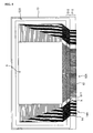
- Organic electroluminescent device using the above phenomenon has the basic structure as shown in FIG. 1.
- the basic structure of organic electroluminescent device includes a glass substrate 1, indium-tin-oxide layers 2 (hereinafter, referred as " anode electrodes") formed on the glass substrate 1 and acting as anode electrode, an insulating layer, an organic electroluminescence layer 3 formed with organic material, and metal layers 4 (hereinafter, referred as " cathode electrodes”) acting as cathode electrode.
- Walls W are formed to deposit the cathode electrodes 4 into a number of sections on the anode electrodes 2.
- the structural elements constituting the organic electroluminescent device are well known in the field. Therefore, a detailed description thereon is omitted.
- a cap 6 is bonded to a periphery of the substrate 1 by using a sealant 5.
- the area onto which the cap is bonded is an outer portion of the substrate 1, that is, an outer area of the active area.
- the active area is completely separated from the exterior by the cap 6, and only end portions of the anode electrodes 2 and the cathode electrodes 4 are exposed to the exterior.
- a sealed space is formed between the cap 6 and the substrate 1, and the structural elements 2, 3, 4 and W placed in this space are not influenced by the exterior environment such as moisture and the like.
- the cap 6 is made of glass or metal, and an ultraviolet rays-cured adhesive is used as the sealant 5. Also, a getter 8 of moisture absorbent is attached to the lower surface of the cap 6 by a tape 7 (made of organic material)
- FIG. 2 is a plane view of the organic electroluminescent device.
- FIG. 2 shows a state that the cap 6 is removed from the organic electroluminescent device shown in FIG. 1.
- the active area A consisted of the structural elements 2, 3, 4 and W shown in FIG. 1 is illustrated in the form of box.
- a plurality of anode electrodes 2 and a plurality of cathode electrodes 4 formed in the active area A are extended to an outer portion of the active area A, and the end portions of the extended anode electrodes 2 and cathode electrodes 4 (that is, data lines and scan lines) are concentrated at one region of the substrate 1 to form a pad section P.
- a plurality of data lines 2 and a plurality of scan lines 4 extended to an outer portion of the active area A are referred to as “the data line group 2A” and “the scan line group 4A,” respectively.
- the sealant 5 is dispensed on the substrate-bonding area of the cap 6 (corresponding part to the cap-bonding areas S1 and S2 of an outer portion of the substrate 1) or the cap-bonding areas S1 and S2 of the substrate 1.
- the cap 6 is bonded to an outer portion S1 and S2 of the active area A formed on the substrate 1.
- ultraviolet rays are radiated selectively onto the cap-bonding areas S1 and S2 of the substrate 1 to cure the sealant 5.
- the end portions of the scan line group 4A and the data line groups 2A are concentrated and arranged on the pad section P of the substrate 1, and certain space S is formed between the scan line group 4A and the data line group 2A at the cap-bonding area S1 of the substrate 1 adjacent to the pad section P as indicated by "K.”
- this space S prevents the sealant from being uniformly dispensed.
- FIG. 3 is a bottom view of the cap, and shows a state the sealant is dispensed on the lower surface of a periphery of the cap 6.
- the peripheries C1 and C2 on which the sealant 5 is dispensed correspond to the cap-bonding areas S1 and S2 of the substrate in FIG. 2.
- the sealant 5 is not dispensed on each corner of the cap 6 due to the operational characteristic of the dispenser.
- the sealant 5 dispensed on the peripheries C1 and C2 is flowed toward each corner section. Accordingly, the sealant 5 is dispensed onto all peripheries of the cap 6 corresponding to the cap-bonding areas S1 and S2 of an outer portion of the active area A of the substrate 1 to bond the cap 6 and the substrate 1.
- FIG. 4 is a partial sectional view of " K" section in FIG. 2, assuming that the sealant 5 is dispensed on the cap-bonding area S1 of the substrate 1. As illustrated there, the sealants dispensed by the dispenser is not dispensed on each corner section of the substrate 1, and the amount of sealant dispensed on the end portions of the cap-bonding area S1 is much less than other portion of the cap-bonding area.
- the sealant 5 By filling the space S , the amount of the sealant 5 flowed toward the scan line group 4A is decreased, and the scan lines 4 act as an obstacle preventing flow of the sealant. Accordingly, the sealant cannot be dispensed uniformly onto both end portions of the cap-bonding area S1 of the substrate 1 (that is, the scan line groups 4A ).
- the cap 6 can be bonded to the substrate 1 under this condition, the space between the cap 6 and the substrate 1 is not completely sealed due to the area on which the sealant 5 is not dispensed, resulting in exposing the structural elements of the device to the exterior environment.
- the present invention intends to solve the above problem occurred in the course of bonding a cap to a substrate.
- the object of the present invention is to provide an organic electroluminescent device having the structure capable of dispensing a sealant uniformly on all cap-bonding area of a substrate.
- an electroluminescent display device comprises a substrate on which an active area is formed; a plurality of scan lines (scan line group) and a plurality of data lines (data line group) extended from cathode electrodes and anode electrodes formed in the active area; auxiliary patterns formed on the substrate, each auxiliary pattern being formed in the space between two adjacent line groups arranged on a cap-bonding area of the substrate; and a cap bonded to the cap-bonding area through a sealant.
- the auxiliary pattern is a metal layer formed on the substrate and the metal layer is made of one of indium tin oxide and molybdenum. Also, the auxiliary pattern can be consisted of a metal layer formed on the substrate and an insulating layer formed on the metal layer.
- the auxiliary pattern is spaced apart from at least one line group by a predetermined gap or spaced apart from both line groups by a predetermined gap.
- the auxiliary pattern can be consisted of a plurality of unit patterns. At this time, it is desirable that the unit patterns are formed in the same direction as a flow direction of the sealant and spaced apart from each other.
- FIG. 5 is a plane view of the organic electroluminescent device according to the first embodiment of the present invention.
- FIG. 5 shows the state that the cap is removed from the organic electroluminescent device, and an active area A consisted of the structural elements is illustrated in the form of box.
- the structure of the active area consisted of anode electrodes, cathode electrodes and walls is the same as that of the organic electroluminescent device described in FIG. 1. Accordingly, the description thereon is omitted.
- a plurality of anode electrodes 12 and a plurality of cathode electrodes 14 extended to an outer portion of the active area A are referred to as " data line group 12A” and " scan line group 14A” , respectively.
- FIG. 6 is an enlarged partial view of part " X" in FIG. 5, only illustrating an adjacent portion of the data line group 12A and the scan line group 14A in a cap-bonding area S10 adjacent to a pad section P10 of a substrate 10.
- the most important feature of the organic electroluminescent device according to this embodiment is to form an auxiliary pattern 20 in the space S11 between the data line group 12A and the scan line group 14A (hereinafter, referred to as " space" for convenience' s sake) in the cap-bonding area S10 adjacent to the pad section P10.
- the auxiliary pattern 20 is a single pattern having a smaller area than the space S11. That is, the auxiliary pattern 20 is spaced apart from the data line group 12A and the scan line group 14A.
- the auxiliary pattern 20 is formed on the glass substrate 10, and so made of indium-tin-oxide (ITO) or molybdenum in order to be formed securely on the glass substrate 10 without separation.
- ITO indium-tin-oxide
- FIG. 7 which is a sectional view taken along line 7-7 in FIG. 6, when the cap is pressurized toward the substrate 10, the sealant 5 dispensed on the cap-bonding area S10 adjacent to the pad section P10 is flowed toward the scan line group 14A past the space S11. In the flowing course of the sealant 5, the sealant 5 goes over the auxiliary pattern 20 to flow smoothly to the end portion of the cap-bonding area S10 (that is, the scan line group 14A).
- the amount of the sealant 5 remained in the space S11 is decreased as much as the volume of the auxiliary pattern 20. Accordingly, the amount of the sealant as much as the volume of the auxiliary pattern 20 can be further flowed to the end portion of the cap-bonding area S10, and so the sealant can be dispensed on the entire cap-bonding area S10. Consequently, the cap (not shown in FIG. 6 and FIG. 7) can be bonded securely onto the entire surface of the cap-bonding area S10, and so the inner space formed by the cap is completely sealed.
- the metallic particles existing in the sealant has an adverse effect to the function of the device such as a short circuit of the scan lines 14. Accordingly, in order to prevent generation of the metallic particles, it is preferable to form the auxiliary pattern 20 with a metal layer and an insulating layer formed on the metal layer.
- a certain gap should be maintained between the data line group 12A and the auxiliary pattern 20, or between the scan line group 14A and the auxiliary pattern 20. Also, such gaps may be formed between the data line group 12A and the auxiliary pattern 20, and between the scan line group 14A and the auxiliary pattern 20.
- the spacer contained in the sealant is the element used for maintaining a predetermined gap between the cap and the substrate 10.
- the spacer can function well only when the auxiliary pattern 20 is formed shorter than the spacer contained in the sealant in the height.
- the ultraviolet rays can penetrate the glass, the ultraviolet rays are radiated to the substrate 10 to cure the sealant. Accordingly, all the sealant dispensed onto the cap bonding area S10 can be cured completely regardless of the auxiliary pattern 20 located below the sealant.
- FIG. 8 is a plane view of the organic electroluminescent device according to the second embodiment of the present invention. For convenience' s sake, FIG. 8 does not illustrate the cap, and the active area A is illustrated in the form of box.
- FIG. 9 which is an enlarged partial view of part " Y" in FIG. 8, only an adjacent portion of the data line group 12A and the scan line group 14A in the cap-bonding area S10 adjacent to a pad section P10 of the substrate 10 is illustrated.
- auxiliary pattern 30 consisted of a plurality of unit patterns 31, 32, 33 and 34 in the space S11 between the data line group 12A and the scan line group 14A in the cap-bonding area S10 adjacent to the pad section P10 .
- the unit patterns 31, 32, 33 and 34 are formed in the same direction as the flow direction of the sealant (arrow F in FIG. 9) across the space S11. A predetermined gap is formed between the adjacent unit patterns.
- the unit pattern 31, 32, 33 and 34 are formed on the glass substrate 10, and so made of indium-tin-oxide (ITO) or molybdenum in order to be formed securely on the glass substrate 10 without separation.
- ITO indium-tin-oxide
- the sealant 5 dispensed on the cap-bonding area S10 adjacent to the pad section P10 goes past the space S11, and flows toward the scan line group 14A.
- the sealant 5 smoothly flows to the end portion of the cap-bonding area S10 (that is, the scan line group 14A) over the unit patterns 31, 32, 33 and 34.
- the amount of the sealant 5 remained in the space S11 is decreased as much as the volume of all the unit patterns 31, 32, 33 and 34 constituting the auxiliary pattern 30. Accordingly, the amount of the sealant as much as the volume of the auxiliary pattern 30 can be further flowed to the end portion of the cap-bonding area S10 so that the sealant can be dispensed on the entire cap-bonding area S10. Consequently, the cap (not shown in FIG. 8 and FIG. 9) can be bonded securely on the entire surface of the cap-bonding area S10, and so the inner space formed by the cap is completely sealed.
- each of the unit patterns 31, 32, 33 and 34 with a metal layer and an insulating layer formed on the metal layer.
- a certain gap should be formed between the data line group 12A and the auxiliary pattern 30 (that is, the unit patterns 31, 32, 33 and 34), or between the scan line group 14A and the auxiliary pattern 30. Also, such gaps may be formed between the data line group 12A and the auxiliary pattern 30, and between the scan line group 14A and the auxiliary pattern 30.
- the spacer contained in the sealant is the element used for maintaining a predetermined interval between the cap and the substrate 10.
- the spacer can function well only if the unit patterns 31, 32, 33 and 34 are formed shorter than the spacer contained in the sealant in the height.
- FIG. 9 shows the unit patterns 31, 32, 33 and 34 formed in the same direction as the flow direction of the sealant 5 (arrow F in FIG. 9) across the space S11, spaced apart from each other.
- the reason that the unit patterns 31, 32, 33 and 34 are arranged as shown above is as follows.
- the ultraviolet rays are radiated onto the lower surface of the substrate 10 to cure the sealant.
- the ultraviolet rays cannot penetrate metal material, and so cannot penetrate the unit patterns 31, 32, 33 and 34 containing ITO or molybdenum, either. If the auxiliary pattern 30 is formed as single pattern, the sealant dispensed onto the auxiliary pattern cannot be cured, and incomplete cure of the sealant has an adverse effect to subsequent processes and the device' s function.
- the auxiliary pattern 30 consists of a plurality of unit patterns 31, 32, 33 and 34 spaced apart from each other. Accordingly, the ultraviolet rays can pass through each gap between the adjacent unit patterns, to cure the sealant existing between the adjacent two unit patterns. In particular, the sealant existing on each unit pattern may be cured by diffused ultraviolet rays.
- a plurality of unit patterns 31, 32, 33 and 34 are formed in the same direction as the flow direction of the sealant 5 (arrow F in FIG. 9) across the space S11, and so the sealant can be flowed smoothly to the end portion of the cap-bonding area S10 without any hindrance.
- the sealant is dispensed uniformly on the entire cap-bonding area so that the glass cap or the metal cap can be bonded securely to the entire cap-bonding area of the substrate. Consequently, all the elements of the device are separated completely from the exterior environment, and so reliability of the device can be enhanced.
Abstract
Description
- The present invention relates to an organic electroluminescent device, particularly to an organic electroluminescent device having the structure capable of dispensing a sealant uniformly on the entire cap-bonding area of a substrate.
- Organic electroluminescence is the phenomenon that excitons are formed in an (low molecular or high molecular) organic material thin film by re-combining holes injected through an anode with electrons injected through a cathode, and a light of specific wavelength is generated by energy from the formed excitons.
- Organic electroluminescent device using the above phenomenon has the basic structure as shown in FIG. 1. The basic structure of organic electroluminescent device includes a
glass substrate 1, indium-tin-oxide layers 2 (hereinafter, referred as " anode electrodes") formed on theglass substrate 1 and acting as anode electrode, an insulating layer, anorganic electroluminescence layer 3 formed with organic material, and metal layers 4 (hereinafter, referred as " cathode electrodes") acting as cathode electrode. Walls W are formed to deposit thecathode electrodes 4 into a number of sections on theanode electrodes 2. - The structural elements constituting the organic electroluminescent device are well known in the field. Therefore, a detailed description thereon is omitted.
- After the active area consisted of the
structural elements cap 6 is bonded to a periphery of thesubstrate 1 by using asealant 5. The area onto which the cap is bonded is an outer portion of thesubstrate 1, that is, an outer area of the active area. The active area is completely separated from the exterior by thecap 6, and only end portions of theanode electrodes 2 and thecathode electrodes 4 are exposed to the exterior. - As shown in FIG. 1, a sealed space is formed between the
cap 6 and thesubstrate 1, and thestructural elements cap 6 is made of glass or metal, and an ultraviolet rays-cured adhesive is used as thesealant 5. Also, agetter 8 of moisture absorbent is attached to the lower surface of thecap 6 by a tape 7 (made of organic material) - FIG. 2 is a plane view of the organic electroluminescent device. For convenience' s sake, FIG. 2 shows a state that the
cap 6 is removed from the organic electroluminescent device shown in FIG. 1. Also, in FIG. 2, the active area A consisted of thestructural elements - As shown in FIG. 2, a plurality of
anode electrodes 2 and a plurality ofcathode electrodes 4 formed in the active area A are extended to an outer portion of the active area A, and the end portions of the extendedanode electrodes 2 and cathode electrodes 4 (that is, data lines and scan lines) are concentrated at one region of thesubstrate 1 to form a pad section P. - Hereinafter, on the other hand, a plurality of
data lines 2 and a plurality ofscan lines 4 extended to an outer portion of the active area A are referred to as " thedata line group 2A" and " thescan line group 4A," respectively. - The process for bonding the
cap 6 to thesubstrate 1 as described above is briefly described with reference to FIG. 1 and FIG. 2 below. - After the
getter 8 is attached to thecap 6 loaded on a cap tray (not shown), thesealant 5 is dispensed on the substrate-bonding area of the cap 6 (corresponding part to the cap-bonding areas S1 and S2 of an outer portion of the substrate 1) or the cap-bonding areas S1 and S2 of thesubstrate 1. After thesubstrate 1 and thecap 6 are aligned, thecap 6 is bonded to an outer portion S1 and S2 of the active area A formed on thesubstrate 1. And, in order to secure the bonding state of thecap 6, ultraviolet rays are radiated selectively onto the cap-bonding areas S1 and S2 of thesubstrate 1 to cure thesealant 5. - As shown in FIG. 2, the end portions of the
scan line group 4A and thedata line groups 2A are concentrated and arranged on the pad section P of thesubstrate 1, and certain space S is formed between thescan line group 4A and thedata line group 2A at the cap-bonding area S1 of thesubstrate 1 adjacent to the pad section P as indicated by "K." However, this space S prevents the sealant from being uniformly dispensed. - FIG. 3 is a bottom view of the cap, and shows a state the sealant is dispensed on the lower surface of a periphery of the
cap 6. In FIG. 3, the peripheries C1 and C2 on which thesealant 5 is dispensed correspond to the cap-bonding areas S1 and S2 of the substrate in FIG. 2. - In the process of dispensing the
sealant 6 onto thecap 5 through a dispenser (not shown), thesealant 5 is not dispensed on each corner of thecap 6 due to the operational characteristic of the dispenser. In this state, when thecap 6 is pressurized to thesubstrate 1, thesealant 5 dispensed on the peripheries C1 and C2 is flowed toward each corner section. Accordingly, thesealant 5 is dispensed onto all peripheries of thecap 6 corresponding to the cap-bonding areas S1 and S2 of an outer portion of the active area A of thesubstrate 1 to bond thecap 6 and thesubstrate 1. - FIG. 4 is a partial sectional view of " K" section in FIG. 2, assuming that the
sealant 5 is dispensed on the cap-bonding area S1 of thesubstrate 1. As illustrated there, the sealants dispensed by the dispenser is not dispensed on each corner section of thesubstrate 1, and the amount of sealant dispensed on the end portions of the cap-bonding area S1 is much less than other portion of the cap-bonding area. - In this state, when the
cap 6 is pressurized to thesubstrate 1, thesealant 5 is flowed toward the end portion of the cap-bonding area S1 (the arrow direction in FIG. 5). In the course that thesealant 5 moves toward the end portion of the cap-bonding area S1 by pressure from thecap 6, thesealant 5 is flowed into the space S formed between thescan line group 4A and thedata line group 2A, to fill the whole space S. - By filling the space S, the amount of the
sealant 5 flowed toward thescan line group 4A is decreased, and thescan lines 4 act as an obstacle preventing flow of the sealant. Accordingly, the sealant cannot be dispensed uniformly onto both end portions of the cap-bonding area S1 of the substrate 1 (that is, thescan line groups 4A). - Although the
cap 6 can be bonded to thesubstrate 1 under this condition, the space between thecap 6 and thesubstrate 1 is not completely sealed due to the area on which thesealant 5 is not dispensed, resulting in exposing the structural elements of the device to the exterior environment. - The present invention intends to solve the above problem occurred in the course of bonding a cap to a substrate. Thus, the object of the present invention is to provide an organic electroluminescent device having the structure capable of dispensing a sealant uniformly on all cap-bonding area of a substrate.
- For achieving the above objects, an electroluminescent display device according to the present invention comprises a substrate on which an active area is formed; a plurality of scan lines (scan line group) and a plurality of data lines (data line group) extended from cathode electrodes and anode electrodes formed in the active area; auxiliary patterns formed on the substrate, each auxiliary pattern being formed in the space between two adjacent line groups arranged on a cap-bonding area of the substrate; and a cap bonded to the cap-bonding area through a sealant.
- The auxiliary pattern is a metal layer formed on the substrate and the metal layer is made of one of indium tin oxide and molybdenum. Also, the auxiliary pattern can be consisted of a metal layer formed on the substrate and an insulating layer formed on the metal layer.
- On the other hand, the auxiliary pattern is spaced apart from at least one line group by a predetermined gap or spaced apart from both line groups by a predetermined gap.
- Here, the auxiliary pattern can be consisted of a plurality of unit patterns. At this time, it is desirable that the unit patterns are formed in the same direction as a flow direction of the sealant and spaced apart from each other.
- The present invention will be more clearly understood from the detailed description in conjunction with the following drawings.
- FIG. 1 is a sectional view schematically showing the basic structure of an organic electroluminescent device;
- FIG. 2 is a plane view of a substrate constituting the organic electroluminescent device;
- FIG. 3 is a bottom view of a cap;
- FIG. 4 is a partial sectional view of " K" section in FIG. 2, showing the state that a sealant is dispensed on a cap-bonding area of the substrate;
- FIG. 5 is a plane view of a substrate constituting the organic electroluminescent device according to a first embodiment of the present invention;
- FIG. 6 is an enlarged partial view of part " X" in FIG. 5;
- FIG. 7 is a sectional view taken along line 7-7 in FIG. 6;
- FIG. 8 is a plane view of a substrate constituting the organic electroluminescent device according to a second embodiment of the present invention; and
- FIG. 9 is an enlarged partial view of part " Y" in FIG. 8.
- Hereinafter, embodiments of the present invention will be described in detail with reference to those accompanying drawings.
- FIG. 5 is a plane view of the organic electroluminescent device according to the first embodiment of the present invention. For convenience' s sake, FIG. 5 shows the state that the cap is removed from the organic electroluminescent device, and an active area A consisted of the structural elements is illustrated in the form of box.
- In the organic electroluminescent device according to the present invention, the structure of the active area consisted of anode electrodes, cathode electrodes and walls is the same as that of the organic electroluminescent device described in FIG. 1. Accordingly, the description thereon is omitted. Hereinafter, on the other hand, a plurality of
anode electrodes 12 and a plurality ofcathode electrodes 14 extended to an outer portion of the active area A are referred to as "data line group 12A" and "scan line group 14A" , respectively. - Also, FIG. 6 is an enlarged partial view of part " X" in FIG. 5, only illustrating an adjacent portion of the
data line group 12A and thescan line group 14A in a cap-bonding area S10 adjacent to a pad section P10 of asubstrate 10. - The most important feature of the organic electroluminescent device according to this embodiment is to form an
auxiliary pattern 20 in the space S11 between thedata line group 12A and thescan line group 14A (hereinafter, referred to as " space" for convenience' s sake) in the cap-bonding area S10 adjacent to the pad section P10. - The
auxiliary pattern 20 is a single pattern having a smaller area than the space S11. That is, theauxiliary pattern 20 is spaced apart from thedata line group 12A and thescan line group 14A. Theauxiliary pattern 20 is formed on theglass substrate 10, and so made of indium-tin-oxide (ITO) or molybdenum in order to be formed securely on theglass substrate 10 without separation. - As shown in FIG. 7 which is a sectional view taken along line 7-7 in FIG. 6, when the cap is pressurized toward the
substrate 10, thesealant 5 dispensed on the cap-bonding area S10 adjacent to the pad section P10 is flowed toward thescan line group 14A past the space S11. In the flowing course of thesealant 5, thesealant 5 goes over theauxiliary pattern 20 to flow smoothly to the end portion of the cap-bonding area S10 (that is, thescan line group 14A). - Here, compared with the structure in FIG. 4, the amount of the
sealant 5 remained in the space S11 is decreased as much as the volume of theauxiliary pattern 20. Accordingly, the amount of the sealant as much as the volume of theauxiliary pattern 20 can be further flowed to the end portion of the cap-bonding area S10, and so the sealant can be dispensed on the entire cap-bonding area S10. Consequently, the cap (not shown in FIG. 6 and FIG. 7) can be bonded securely onto the entire surface of the cap-bonding area S10, and so the inner space formed by the cap is completely sealed. - On the other hand, a large amount of spacer is contained in the sealant. Thus, the spacer is contacted with the
auxiliary pattern 20 of metal layer in the flowing course of the sealant. As a result, metallic particles are generated and remained in the sealant. - The metallic particles existing in the sealant has an adverse effect to the function of the device such as a short circuit of the scan lines 14. Accordingly, in order to prevent generation of the metallic particles, it is preferable to form the
auxiliary pattern 20 with a metal layer and an insulating layer formed on the metal layer. - Also, in order to prevent the short circuit of the
data line 12 and thescan line 14, a certain gap should be maintained between thedata line group 12A and theauxiliary pattern 20, or between thescan line group 14A and theauxiliary pattern 20. Also, such gaps may be formed between thedata line group 12A and theauxiliary pattern 20, and between thescan line group 14A and theauxiliary pattern 20. - Here, the spacer contained in the sealant is the element used for maintaining a predetermined gap between the cap and the
substrate 10. Thus, the spacer can function well only when theauxiliary pattern 20 is formed shorter than the spacer contained in the sealant in the height. - As described above, on the other hand, in the case that the glass cap is bonded to the substrate, since the ultraviolet rays can penetrate the glass, the ultraviolet rays are radiated to the
substrate 10 to cure the sealant. Accordingly, all the sealant dispensed onto the cap bonding area S10 can be cured completely regardless of theauxiliary pattern 20 located below the sealant. - FIG. 8 is a plane view of the organic electroluminescent device according to the second embodiment of the present invention. For convenience' s sake, FIG. 8 does not illustrate the cap, and the active area A is illustrated in the form of box.
- Like FIG. 6, in FIG. 9 which is an enlarged partial view of part " Y" in FIG. 8, only an adjacent portion of the
data line group 12A and thescan line group 14A in the cap-bonding area S10 adjacent to a pad section P10 of thesubstrate 10 is illustrated. - The most important feature of the organic electroluminescent device according to this embodiment is to form an
auxiliary pattern 30 consisted of a plurality ofunit patterns data line group 12A and thescan line group 14A in the cap-bonding area S10 adjacent to the pad section P10. - The
unit patterns - The
unit pattern glass substrate 10, and so made of indium-tin-oxide (ITO) or molybdenum in order to be formed securely on theglass substrate 10 without separation. - Like the condition as shown in FIG. 7, when the cap is pressurized toward the
substrate 10, thesealant 5 dispensed on the cap-bonding area S10 adjacent to the pad section P10 goes past the space S11, and flows toward thescan line group 14A. In the flowing course of thesealant 5, thesealant 5 smoothly flows to the end portion of the cap-bonding area S10 (that is, thescan line group 14A) over theunit patterns - Here, compared with the structure in FIG. 4, the amount of the
sealant 5 remained in the space S11 is decreased as much as the volume of all theunit patterns auxiliary pattern 30. Accordingly, the amount of the sealant as much as the volume of theauxiliary pattern 30 can be further flowed to the end portion of the cap-bonding area S10 so that the sealant can be dispensed on the entire cap-bonding area S10. Consequently, the cap (not shown in FIG. 8 and FIG. 9) can be bonded securely on the entire surface of the cap-bonding area S10, and so the inner space formed by the cap is completely sealed. - As described above, a large amount of spacer is contained in the sealant. Thus, the spacer is contacted with the
unit patterns - The metallic particles existing in the sealant affect adversely the function of the device such as a short circuit of the scan lines 14. Accordingly, in order to prevent generation of the metallic particles, it is preferable to form each of the
unit patterns - On the other hand, in order to prevent generation of the short circuit between the
data line 12 and thescan line 14, a certain gap should be formed between thedata line group 12A and the auxiliary pattern 30 (that is, theunit patterns scan line group 14A and theauxiliary pattern 30. Also, such gaps may be formed between thedata line group 12A and theauxiliary pattern 30, and between thescan line group 14A and theauxiliary pattern 30. - Here, the spacer contained in the sealant is the element used for maintaining a predetermined interval between the cap and the
substrate 10. Thus, the spacer can function well only if theunit patterns - FIG. 9 shows the
unit patterns unit patterns - As described above, after the metal cap is bonded to the substrate through the dispensed sealant, the ultraviolet rays are radiated onto the lower surface of the
substrate 10 to cure the sealant. The ultraviolet rays cannot penetrate metal material, and so cannot penetrate theunit patterns auxiliary pattern 30 is formed as single pattern, the sealant dispensed onto the auxiliary pattern cannot be cured, and incomplete cure of the sealant has an adverse effect to subsequent processes and the device' s function. - In this embodiment, in order to prevent the above mentioned problem, the
auxiliary pattern 30 consists of a plurality ofunit patterns - Also, a plurality of
unit patterns - In the organic electroluminescent device according to the present invention as described above, the sealant is dispensed uniformly on the entire cap-bonding area so that the glass cap or the metal cap can be bonded securely to the entire cap-bonding area of the substrate. Consequently, all the elements of the device are separated completely from the exterior environment, and so reliability of the device can be enhanced.
- The preferred embodiments of the present invention have been described for illustrative purposes, and those skilled in the art will appreciate that various modifications, additions, and substitutions are possible, without departing from the scope and spirit of the present invention as disclosed in the accompanying claims.
Claims (20)
- An organic electroluminescent device, comprising
a substrate on which an active area is formed;
a plurality of scan lines (scan line group) and a plurality of data lines (data line group) extended from cathode electrodes and anode electrodes formed in the active area;
auxiliary patterns formed on the substrate, each auxiliary pattern being formed in the space between two adjacent line groups arranged on a cap-bonding area of the substrate; and
a cap bonded to the cap-bonding area through a sealant. - The organic electroluminescent device according to claim 1, wherein the auxiliary pattern is a metal layer formed on the substrate.
- The organic electroluminescent device according to claim 2, wherein the metal layer is made of one of indium tin oxide and molybdenum.
- The organic electroluminescent device according to claim 1, wherein the auxiliary pattern consists of a metal layer formed on the substrate and an insulating layer formed on the metal layer.
- The organic electroluminescent device according to claim 4, wherein the metal layer is made of one of indium tin oxide and molybdenum.
- The organic electroluminescent device according to claim 1, wherein the auxiliary pattern is shorter than a spacer contained in the sealant in the height.
- The organic electroluminescent device according to claim 1, wherein the auxiliary pattern is spaced apart from at least one line group by a predetermined gap.
- The organic electroluminescent device according to claim 1, wherein the auxiliary pattern is spaced apart from both line groups by a predetermined gap.
- The organic electroluminescent device according to claim 1, wherein the auxiliary pattern consists of at least two unit patterns.
- The organic electroluminescent device according to claim 9, wherein the unit patterns are formed in the same direction as a flow direction of the sealant and spaced apart from each other.
- An organic electroluminescent device, comprising
a substrate on which an active area is formed;
a plurality of scan lines (scan line group) and a plurality of data lines (data line group) extended from cathode electrodes and anode electrodes formed in the active area;
auxiliary patterns formed on the substrate, each auxiliary pattern consisted of at least two unit patterns and formed in the space between two adjacent line groups arranged on a cap-bonding area of the substrate; and
a cap bonded to the cap-bonding area through a sealant. - The organic electroluminescent device according to claim 11, wherein the unit pattern is a metal layer formed on the substrate.
- The organic electroluminescent device according to claim 12, wherein the metal layer is made of one of indium tin oxide and molybdenum.
- The organic electroluminescent device according to claim 11, wherein the unit pattern consists of a metal layer formed on the substrate and an insulating layer formed on the metal layer.
- The organic electroluminescent device according to claim 14, wherein the metal layer is made of one of indium tin oxide and molybdenum.
- The organic electroluminescent device according to claim 11, wherein the unit pattern is shorter than a spacer contained in the sealant in the height.
- The organic electroluminescent device according to claim 11, wherein the unit patterns are formed in the same direction as a flow direction of the sealant and spaced apart from each other.
- The organic electroluminescent device according to claim 11, wherein the unit pattern is spaced apart from at least one line group by a predetermined gap.
- The organic electroluminescent device according to claim 11, wherein the unit pattern is spaced apart from both line groups by a predetermined gap.
- The display device according to claim 11, wherein the cap is made of glass or metal.
Applications Claiming Priority (2)
| Application Number | Priority Date | Filing Date | Title |
|---|---|---|---|
| KR1020050041243A KR100702517B1 (en) | 2005-05-17 | 2005-05-17 | Organic electroluminescent device |
| KR1020050041245A KR100702518B1 (en) | 2005-05-17 | 2005-05-17 | Organic electroluminescent device |
Publications (3)
| Publication Number | Publication Date |
|---|---|
| EP1724853A2 true EP1724853A2 (en) | 2006-11-22 |
| EP1724853A3 EP1724853A3 (en) | 2011-03-09 |
| EP1724853B1 EP1724853B1 (en) | 2015-05-06 |
Family
ID=36831267
Family Applications (1)
| Application Number | Title | Priority Date | Filing Date |
|---|---|---|---|
| EP20060005003 Active EP1724853B1 (en) | 2005-05-17 | 2006-03-11 | Organic electroluminescent device |
Country Status (3)
| Country | Link |
|---|---|
| US (1) | US7830087B2 (en) |
| EP (1) | EP1724853B1 (en) |
| JP (1) | JP2006324231A (en) |
Families Citing this family (2)
| Publication number | Priority date | Publication date | Assignee | Title |
|---|---|---|---|---|
| JP5471317B2 (en) * | 2009-11-05 | 2014-04-16 | 日本精機株式会社 | Organic EL panel |
| JP6378154B2 (en) * | 2015-10-08 | 2018-08-22 | 双葉電子工業株式会社 | Organic EL display device |
Citations (4)
| Publication number | Priority date | Publication date | Assignee | Title |
|---|---|---|---|---|
| JP2001189190A (en) * | 2000-01-06 | 2001-07-10 | Auto Network Gijutsu Kenkyusho:Kk | Organic el display device |
| JP2003249347A (en) * | 2002-02-26 | 2003-09-05 | Toyota Industries Corp | Electro-optic panel |
| US20040041973A1 (en) * | 2002-09-04 | 2004-03-04 | Lg.Philips Lcd Co., Ltd. | Liquid crystal display device and method of fabricating the same |
| JP2005019151A (en) * | 2003-06-25 | 2005-01-20 | Tohoku Pioneer Corp | Organic electroluminescent panel and its manufacturing method |
Family Cites Families (9)
| Publication number | Priority date | Publication date | Assignee | Title |
|---|---|---|---|---|
| JPS6424395A (en) * | 1987-07-21 | 1989-01-26 | Oki Electric Ind Co Ltd | Sealing method for sealing plate of el panel |
| JPH09306671A (en) * | 1996-05-21 | 1997-11-28 | Matsushita Electric Ind Co Ltd | Organic thin film electroluminescence element and its driving method |
| US6103547A (en) * | 1997-01-17 | 2000-08-15 | Micron Technology, Inc. | High speed IC package configuration |
| JP2000021567A (en) * | 1998-07-03 | 2000-01-21 | Futaba Corp | Organic el display element |
| KR100768182B1 (en) * | 2001-10-26 | 2007-10-17 | 삼성에스디아이 주식회사 | Organic electro luminescence device and method of manufacturing the same |
| US7038377B2 (en) * | 2002-01-16 | 2006-05-02 | Seiko Epson Corporation | Display device with a narrow frame |
| US20040041520A1 (en) * | 2002-08-27 | 2004-03-04 | Ritdisplay Corporation | Panel for organic electroluminescent device |
| JP3748075B2 (en) * | 2002-08-30 | 2006-02-22 | セイコーエプソン株式会社 | Electronic module, method for manufacturing the same, and electronic device |
| JP4359091B2 (en) * | 2003-07-16 | 2009-11-04 | パイオニア株式会社 | Organic electroluminescence display panel |
-
2006
- 2006-03-11 EP EP20060005003 patent/EP1724853B1/en active Active
- 2006-03-24 US US11/387,853 patent/US7830087B2/en active Active
- 2006-04-06 JP JP2006105660A patent/JP2006324231A/en active Pending
Patent Citations (4)
| Publication number | Priority date | Publication date | Assignee | Title |
|---|---|---|---|---|
| JP2001189190A (en) * | 2000-01-06 | 2001-07-10 | Auto Network Gijutsu Kenkyusho:Kk | Organic el display device |
| JP2003249347A (en) * | 2002-02-26 | 2003-09-05 | Toyota Industries Corp | Electro-optic panel |
| US20040041973A1 (en) * | 2002-09-04 | 2004-03-04 | Lg.Philips Lcd Co., Ltd. | Liquid crystal display device and method of fabricating the same |
| JP2005019151A (en) * | 2003-06-25 | 2005-01-20 | Tohoku Pioneer Corp | Organic electroluminescent panel and its manufacturing method |
Also Published As
| Publication number | Publication date |
|---|---|
| US20060261734A1 (en) | 2006-11-23 |
| EP1724853A3 (en) | 2011-03-09 |
| JP2006324231A (en) | 2006-11-30 |
| EP1724853B1 (en) | 2015-05-06 |
| US7830087B2 (en) | 2010-11-09 |
Similar Documents
| Publication | Publication Date | Title |
|---|---|---|
| CN108832017B (en) | Display panel, manufacturing method thereof, display module and electronic device | |
| JP4458379B2 (en) | Organic EL display device | |
| KR20230029743A (en) | Organic light emitting display device | |
| US11747927B2 (en) | Display panel and display device | |
| CN112563432A (en) | Organic light emitting display panel and method of manufacturing the same | |
| US10276812B2 (en) | Display device and manufacturing method thereof | |
| KR100624131B1 (en) | Organic light emitting display device | |
| US10476030B2 (en) | Display device and manufacturing method thereof | |
| US20200358026A1 (en) | Display substrate, manufacturing method thereof, display device | |
| KR101949926B1 (en) | Organic Light Emitting diode and method of manufacturing the same | |
| EP1724853B1 (en) | Organic electroluminescent device | |
| US7638942B2 (en) | Encapsulation cap having a getter and display device using the same | |
| KR100702517B1 (en) | Organic electroluminescent device | |
| JP6854240B2 (en) | Organic EL devices, organic EL lighting panels, organic EL lighting devices and organic EL displays | |
| KR20030082646A (en) | Eletroluminesence device and method of fabricating the same | |
| KR100508948B1 (en) | Organic electro luminescence display device | |
| KR100702518B1 (en) | Organic electroluminescent device | |
| KR100619626B1 (en) | Flat panel display device | |
| KR101149937B1 (en) | Organic electroluminescent device | |
| CN115050793B (en) | Display panel | |
| JP2002008855A (en) | Organic el panel | |
| JP7390508B2 (en) | Light-emitting device and method for manufacturing the light-emitting device | |
| KR100726941B1 (en) | Organic Electro-Luminescence Display Device And Fabricating Method Thereof | |
| KR100588062B1 (en) | Organic electroluminescent device | |
| KR100638032B1 (en) | Organic electroluminescent device |
Legal Events
| Date | Code | Title | Description |
|---|---|---|---|
| PUAI | Public reference made under article 153(3) epc to a published international application that has entered the european phase |
Free format text: ORIGINAL CODE: 0009012 |
|
| 17P | Request for examination filed |
Effective date: 20060311 |
|
| AK | Designated contracting states |
Kind code of ref document: A2 Designated state(s): AT BE BG CH CY CZ DE DK EE ES FI FR GB GR HU IE IS IT LI LT LU LV MC NL PL PT RO SE SI SK TR |
|
| AX | Request for extension of the european patent |
Extension state: AL BA HR MK YU |
|
| RAP1 | Party data changed (applicant data changed or rights of an application transferred) |
Owner name: LG DISPLAY CO., LTD. |
|
| RAP1 | Party data changed (applicant data changed or rights of an application transferred) |
Owner name: LG DISPLAY CO., LTD. |
|
| PUAL | Search report despatched |
Free format text: ORIGINAL CODE: 0009013 |
|
| AK | Designated contracting states |
Kind code of ref document: A3 Designated state(s): AT BE BG CH CY CZ DE DK EE ES FI FR GB GR HU IE IS IT LI LT LU LV MC NL PL PT RO SE SI SK TR |
|
| AX | Request for extension of the european patent |
Extension state: AL BA HR MK YU |
|
| AKX | Designation fees paid |
Designated state(s): AT BE BG CH CY CZ DE DK EE ES FI FR GB GR HU IE IS IT LI LT LU LV MC NL PL PT RO SE SI SK TR |
|
| 17Q | First examination report despatched |
Effective date: 20120705 |
|
| REG | Reference to a national code |
Ref country code: DE Ref legal event code: R079 Ref document number: 602006045334 Country of ref document: DE Free format text: PREVIOUS MAIN CLASS: H01L0051520000 Ipc: H01L0027320000 |
|
| RIC1 | Information provided on ipc code assigned before grant |
Ipc: H01L 51/52 20060101ALI20141007BHEP Ipc: H01L 27/32 20060101AFI20141007BHEP |
|
| GRAP | Despatch of communication of intention to grant a patent |
Free format text: ORIGINAL CODE: EPIDOSNIGR1 |
|
| INTG | Intention to grant announced |
Effective date: 20141113 |
|
| RAP1 | Party data changed (applicant data changed or rights of an application transferred) |
Owner name: LG DISPLAY CO., LTD. |
|
| GRAS | Grant fee paid |
Free format text: ORIGINAL CODE: EPIDOSNIGR3 |
|
| GRAA | (expected) grant |
Free format text: ORIGINAL CODE: 0009210 |
|
| AK | Designated contracting states |
Kind code of ref document: B1 Designated state(s): AT BE BG CH CY CZ DE DK EE ES FI FR GB GR HU IE IS IT LI LT LU LV MC NL PL PT RO SE SI SK TR |
|
| REG | Reference to a national code |
Ref country code: GB Ref legal event code: FG4D |
|
| REG | Reference to a national code |
Ref country code: CH Ref legal event code: EP |
|
| REG | Reference to a national code |
Ref country code: IE Ref legal event code: FG4D |
|
| REG | Reference to a national code |
Ref country code: AT Ref legal event code: REF Ref document number: 726225 Country of ref document: AT Kind code of ref document: T Effective date: 20150615 |
|
| REG | Reference to a national code |
Ref country code: DE Ref legal event code: R096 Ref document number: 602006045334 Country of ref document: DE Effective date: 20150618 |
|
| REG | Reference to a national code |
Ref country code: AT Ref legal event code: MK05 Ref document number: 726225 Country of ref document: AT Kind code of ref document: T Effective date: 20150506 |
|
| REG | Reference to a national code |
Ref country code: NL Ref legal event code: MP Effective date: 20150506 |
|
| REG | Reference to a national code |
Ref country code: LT Ref legal event code: MG4D |
|
| PG25 | Lapsed in a contracting state [announced via postgrant information from national office to epo] |
Ref country code: PT Free format text: LAPSE BECAUSE OF FAILURE TO SUBMIT A TRANSLATION OF THE DESCRIPTION OR TO PAY THE FEE WITHIN THE PRESCRIBED TIME-LIMIT Effective date: 20150907 Ref country code: ES Free format text: LAPSE BECAUSE OF FAILURE TO SUBMIT A TRANSLATION OF THE DESCRIPTION OR TO PAY THE FEE WITHIN THE PRESCRIBED TIME-LIMIT Effective date: 20150506 Ref country code: LT Free format text: LAPSE BECAUSE OF FAILURE TO SUBMIT A TRANSLATION OF THE DESCRIPTION OR TO PAY THE FEE WITHIN THE PRESCRIBED TIME-LIMIT Effective date: 20150506 Ref country code: FI Free format text: LAPSE BECAUSE OF FAILURE TO SUBMIT A TRANSLATION OF THE DESCRIPTION OR TO PAY THE FEE WITHIN THE PRESCRIBED TIME-LIMIT Effective date: 20150506 |
|
| PG25 | Lapsed in a contracting state [announced via postgrant information from national office to epo] |
Ref country code: LV Free format text: LAPSE BECAUSE OF FAILURE TO SUBMIT A TRANSLATION OF THE DESCRIPTION OR TO PAY THE FEE WITHIN THE PRESCRIBED TIME-LIMIT Effective date: 20150506 Ref country code: BG Free format text: LAPSE BECAUSE OF FAILURE TO SUBMIT A TRANSLATION OF THE DESCRIPTION OR TO PAY THE FEE WITHIN THE PRESCRIBED TIME-LIMIT Effective date: 20150806 Ref country code: AT Free format text: LAPSE BECAUSE OF FAILURE TO SUBMIT A TRANSLATION OF THE DESCRIPTION OR TO PAY THE FEE WITHIN THE PRESCRIBED TIME-LIMIT Effective date: 20150506 Ref country code: IS Free format text: LAPSE BECAUSE OF FAILURE TO SUBMIT A TRANSLATION OF THE DESCRIPTION OR TO PAY THE FEE WITHIN THE PRESCRIBED TIME-LIMIT Effective date: 20150906 Ref country code: GR Free format text: LAPSE BECAUSE OF FAILURE TO SUBMIT A TRANSLATION OF THE DESCRIPTION OR TO PAY THE FEE WITHIN THE PRESCRIBED TIME-LIMIT Effective date: 20150807 |
|
| REG | Reference to a national code |
Ref country code: FR Ref legal event code: PLFP Year of fee payment: 11 |
|
| PG25 | Lapsed in a contracting state [announced via postgrant information from national office to epo] |
Ref country code: EE Free format text: LAPSE BECAUSE OF FAILURE TO SUBMIT A TRANSLATION OF THE DESCRIPTION OR TO PAY THE FEE WITHIN THE PRESCRIBED TIME-LIMIT Effective date: 20150506 Ref country code: DK Free format text: LAPSE BECAUSE OF FAILURE TO SUBMIT A TRANSLATION OF THE DESCRIPTION OR TO PAY THE FEE WITHIN THE PRESCRIBED TIME-LIMIT Effective date: 20150506 |
|
| REG | Reference to a national code |
Ref country code: DE Ref legal event code: R097 Ref document number: 602006045334 Country of ref document: DE |
|
| PG25 | Lapsed in a contracting state [announced via postgrant information from national office to epo] |
Ref country code: RO Free format text: LAPSE BECAUSE OF NON-PAYMENT OF DUE FEES Effective date: 20150506 Ref country code: PL Free format text: LAPSE BECAUSE OF FAILURE TO SUBMIT A TRANSLATION OF THE DESCRIPTION OR TO PAY THE FEE WITHIN THE PRESCRIBED TIME-LIMIT Effective date: 20150506 Ref country code: CZ Free format text: LAPSE BECAUSE OF FAILURE TO SUBMIT A TRANSLATION OF THE DESCRIPTION OR TO PAY THE FEE WITHIN THE PRESCRIBED TIME-LIMIT Effective date: 20150506 Ref country code: SK Free format text: LAPSE BECAUSE OF FAILURE TO SUBMIT A TRANSLATION OF THE DESCRIPTION OR TO PAY THE FEE WITHIN THE PRESCRIBED TIME-LIMIT Effective date: 20150506 |
|
| PLBE | No opposition filed within time limit |
Free format text: ORIGINAL CODE: 0009261 |
|
| STAA | Information on the status of an ep patent application or granted ep patent |
Free format text: STATUS: NO OPPOSITION FILED WITHIN TIME LIMIT |
|
| 26N | No opposition filed |
Effective date: 20160209 |
|
| PG25 | Lapsed in a contracting state [announced via postgrant information from national office to epo] |
Ref country code: IT Free format text: LAPSE BECAUSE OF FAILURE TO SUBMIT A TRANSLATION OF THE DESCRIPTION OR TO PAY THE FEE WITHIN THE PRESCRIBED TIME-LIMIT Effective date: 20150506 |
|
| PG25 | Lapsed in a contracting state [announced via postgrant information from national office to epo] |
Ref country code: SI Free format text: LAPSE BECAUSE OF FAILURE TO SUBMIT A TRANSLATION OF THE DESCRIPTION OR TO PAY THE FEE WITHIN THE PRESCRIBED TIME-LIMIT Effective date: 20150506 |
|
| PG25 | Lapsed in a contracting state [announced via postgrant information from national office to epo] |
Ref country code: BE Free format text: LAPSE BECAUSE OF FAILURE TO SUBMIT A TRANSLATION OF THE DESCRIPTION OR TO PAY THE FEE WITHIN THE PRESCRIBED TIME-LIMIT Effective date: 20150506 |
|
| PG25 | Lapsed in a contracting state [announced via postgrant information from national office to epo] |
Ref country code: MC Free format text: LAPSE BECAUSE OF FAILURE TO SUBMIT A TRANSLATION OF THE DESCRIPTION OR TO PAY THE FEE WITHIN THE PRESCRIBED TIME-LIMIT Effective date: 20150506 Ref country code: LU Free format text: LAPSE BECAUSE OF FAILURE TO SUBMIT A TRANSLATION OF THE DESCRIPTION OR TO PAY THE FEE WITHIN THE PRESCRIBED TIME-LIMIT Effective date: 20160311 |
|
| REG | Reference to a national code |
Ref country code: CH Ref legal event code: PL |
|
| REG | Reference to a national code |
Ref country code: IE Ref legal event code: MM4A |
|
| REG | Reference to a national code |
Ref country code: FR Ref legal event code: PLFP Year of fee payment: 12 |
|
| PG25 | Lapsed in a contracting state [announced via postgrant information from national office to epo] |
Ref country code: CH Free format text: LAPSE BECAUSE OF NON-PAYMENT OF DUE FEES Effective date: 20160331 Ref country code: LI Free format text: LAPSE BECAUSE OF NON-PAYMENT OF DUE FEES Effective date: 20160331 Ref country code: IE Free format text: LAPSE BECAUSE OF NON-PAYMENT OF DUE FEES Effective date: 20160311 |
|
| PG25 | Lapsed in a contracting state [announced via postgrant information from national office to epo] |
Ref country code: SE Free format text: LAPSE BECAUSE OF FAILURE TO SUBMIT A TRANSLATION OF THE DESCRIPTION OR TO PAY THE FEE WITHIN THE PRESCRIBED TIME-LIMIT Effective date: 20150506 Ref country code: NL Free format text: LAPSE BECAUSE OF FAILURE TO SUBMIT A TRANSLATION OF THE DESCRIPTION OR TO PAY THE FEE WITHIN THE PRESCRIBED TIME-LIMIT Effective date: 20150506 |
|
| REG | Reference to a national code |
Ref country code: FR Ref legal event code: PLFP Year of fee payment: 13 |
|
| PG25 | Lapsed in a contracting state [announced via postgrant information from national office to epo] |
Ref country code: CY Free format text: LAPSE BECAUSE OF FAILURE TO SUBMIT A TRANSLATION OF THE DESCRIPTION OR TO PAY THE FEE WITHIN THE PRESCRIBED TIME-LIMIT Effective date: 20150506 Ref country code: HU Free format text: LAPSE BECAUSE OF FAILURE TO SUBMIT A TRANSLATION OF THE DESCRIPTION OR TO PAY THE FEE WITHIN THE PRESCRIBED TIME-LIMIT; INVALID AB INITIO Effective date: 20060311 |
|
| PG25 | Lapsed in a contracting state [announced via postgrant information from national office to epo] |
Ref country code: TR Free format text: LAPSE BECAUSE OF FAILURE TO SUBMIT A TRANSLATION OF THE DESCRIPTION OR TO PAY THE FEE WITHIN THE PRESCRIBED TIME-LIMIT Effective date: 20150506 |
|
| REG | Reference to a national code |
Ref country code: DE Ref legal event code: R079 Ref document number: 602006045334 Country of ref document: DE Free format text: PREVIOUS MAIN CLASS: H01L0027320000 Ipc: H10K0059000000 |
|
| PGFP | Annual fee paid to national office [announced via postgrant information from national office to epo] |
Ref country code: FR Payment date: 20230119 Year of fee payment: 18 |
|
| PGFP | Annual fee paid to national office [announced via postgrant information from national office to epo] |
Ref country code: GB Payment date: 20230119 Year of fee payment: 18 Ref country code: DE Payment date: 20230119 Year of fee payment: 18 |