EP1724799A2 - Elektrische Kontaktverbindung und Verfahren zur Herstellung - Google Patents
Elektrische Kontaktverbindung und Verfahren zur Herstellung Download PDFInfo
- Publication number
- EP1724799A2 EP1724799A2 EP06010028A EP06010028A EP1724799A2 EP 1724799 A2 EP1724799 A2 EP 1724799A2 EP 06010028 A EP06010028 A EP 06010028A EP 06010028 A EP06010028 A EP 06010028A EP 1724799 A2 EP1724799 A2 EP 1724799A2
- Authority
- EP
- European Patent Office
- Prior art keywords
- contact
- contact piece
- piece
- pad
- contact pad
- Prior art date
- Legal status (The legal status is an assumption and is not a legal conclusion. Google has not performed a legal analysis and makes no representation as to the accuracy of the status listed.)
- Granted
Links
- 238000000034 method Methods 0.000 title claims abstract description 9
- 238000004519 manufacturing process Methods 0.000 title claims description 5
- 238000007373 indentation Methods 0.000 claims description 13
- 150000001875 compounds Chemical class 0.000 claims description 10
- 238000004049 embossing Methods 0.000 claims description 7
- 229910000510 noble metal Inorganic materials 0.000 claims 1
- 238000003466 welding Methods 0.000 description 13
- 239000000463 material Substances 0.000 description 5
- 238000010438 heat treatment Methods 0.000 description 3
- RYGMFSIKBFXOCR-UHFFFAOYSA-N Copper Chemical compound [Cu] RYGMFSIKBFXOCR-UHFFFAOYSA-N 0.000 description 2
- 229910045601 alloy Inorganic materials 0.000 description 2
- 239000000956 alloy Substances 0.000 description 2
- 229910052802 copper Inorganic materials 0.000 description 2
- 239000010949 copper Substances 0.000 description 2
- 230000000694 effects Effects 0.000 description 2
- 239000002184 metal Substances 0.000 description 2
- 229910052751 metal Inorganic materials 0.000 description 2
- 230000008092 positive effect Effects 0.000 description 2
- 239000010935 stainless steel Substances 0.000 description 2
- 229910001220 stainless steel Inorganic materials 0.000 description 2
- 229910001369 Brass Inorganic materials 0.000 description 1
- 238000005452 bending Methods 0.000 description 1
- 239000010951 brass Substances 0.000 description 1
- 239000000969 carrier Substances 0.000 description 1
- 230000000994 depressogenic effect Effects 0.000 description 1
- 238000010304 firing Methods 0.000 description 1
- 238000003780 insertion Methods 0.000 description 1
- 230000037431 insertion Effects 0.000 description 1
- 230000013011 mating Effects 0.000 description 1
- 230000004048 modification Effects 0.000 description 1
- 238000012986 modification Methods 0.000 description 1
- 239000010970 precious metal Substances 0.000 description 1
- 238000003825 pressing Methods 0.000 description 1
- 230000000630 rising effect Effects 0.000 description 1
- 238000005096 rolling process Methods 0.000 description 1
- 230000006641 stabilisation Effects 0.000 description 1
- 238000011105 stabilization Methods 0.000 description 1
- 230000007704 transition Effects 0.000 description 1
Images
Classifications
-
- H—ELECTRICITY
- H01—ELECTRIC ELEMENTS
- H01H—ELECTRIC SWITCHES; RELAYS; SELECTORS; EMERGENCY PROTECTIVE DEVICES
- H01H11/00—Apparatus or processes specially adapted for the manufacture of electric switches
- H01H11/04—Apparatus or processes specially adapted for the manufacture of electric switches of switch contacts
- H01H11/041—Apparatus or processes specially adapted for the manufacture of electric switches of switch contacts by bonding of a contact marking face to a contact body portion
- H01H11/042—Apparatus or processes specially adapted for the manufacture of electric switches of switch contacts by bonding of a contact marking face to a contact body portion by mechanical deformation
-
- H—ELECTRICITY
- H01—ELECTRIC ELEMENTS
- H01R—ELECTRICALLY-CONDUCTIVE CONNECTIONS; STRUCTURAL ASSOCIATIONS OF A PLURALITY OF MUTUALLY-INSULATED ELECTRICAL CONNECTING ELEMENTS; COUPLING DEVICES; CURRENT COLLECTORS
- H01R4/00—Electrically-conductive connections between two or more conductive members in direct contact, i.e. touching one another; Means for effecting or maintaining such contact; Electrically-conductive connections having two or more spaced connecting locations for conductors and using contact members penetrating insulation
- H01R4/02—Soldered or welded connections
-
- H—ELECTRICITY
- H01—ELECTRIC ELEMENTS
- H01H—ELECTRIC SWITCHES; RELAYS; SELECTORS; EMERGENCY PROTECTIVE DEVICES
- H01H1/00—Contacts
- H01H1/02—Contacts characterised by the material thereof
- H01H1/04—Co-operating contacts of different material
-
- H—ELECTRICITY
- H01—ELECTRIC ELEMENTS
- H01H—ELECTRIC SWITCHES; RELAYS; SELECTORS; EMERGENCY PROTECTIVE DEVICES
- H01H1/00—Contacts
- H01H1/06—Contacts characterised by the shape or structure of the contact-making surface, e.g. grooved
-
- H—ELECTRICITY
- H01—ELECTRIC ELEMENTS
- H01H—ELECTRIC SWITCHES; RELAYS; SELECTORS; EMERGENCY PROTECTIVE DEVICES
- H01H1/00—Contacts
- H01H1/12—Contacts characterised by the manner in which co-operating contacts engage
- H01H1/14—Contacts characterised by the manner in which co-operating contacts engage by abutting
- H01H1/24—Contacts characterised by the manner in which co-operating contacts engage by abutting with resilient mounting
-
- H—ELECTRICITY
- H01—ELECTRIC ELEMENTS
- H01H—ELECTRIC SWITCHES; RELAYS; SELECTORS; EMERGENCY PROTECTIVE DEVICES
- H01H11/00—Apparatus or processes specially adapted for the manufacture of electric switches
- H01H11/04—Apparatus or processes specially adapted for the manufacture of electric switches of switch contacts
- H01H11/041—Apparatus or processes specially adapted for the manufacture of electric switches of switch contacts by bonding of a contact marking face to a contact body portion
Definitions
- the invention relates to a connection of a contact piece on a contact pad as a contact connection, wherein the contact piece has a contact surface, to which usually a mating contact can be applied. Likewise, the invention relates to a method for producing this contact compound.
- contacts or contact heads on contact pads It is known to weld contacts or contact heads on contact pads. This is done, for example, as contacts for electromechanical switching devices, such as those from the EP 898 291 A1 are known. Such contacts may also be formed as so-called bimetallic contacts, that is, with two different metal layers or metal parts. The problem is often the durability of the attachment or welding of the contact piece on the contact pad, especially if it is a bimetallic contact.
- the invention has for its object to provide an aforementioned compound and a method for producing such a compound with which problems of the prior art can be avoided, and in particular achieves a simpler, secure and permanent attachment of a contact piece or contact head on a contact pad can be.
- the stamping causes such distortion by the resulting deformation, whereby the entire compound is solidified and stabilized. This also causes the contact piece to assume a curved shape, whereby the outer edges are depressed and thus the connection is better maintained.
- the imprint acts as a kind of positive locking at least against laterally acting forces. This also makes the connection more stable.
- the indentation can be so strong or be designed so that the surface is convexly convex on a flat contact piece. If the contact piece is already curved, this curvature can still be reinforced convex. It is advantageously possible during the embossing to attach the contact piece to a kind of counter bearing, so that it can not be detached or struck away from the contact pad. Particularly advantageous is an abutment provided in such a way with a desired shape for the contact piece, that the surface of the contact piece is so to speak beaten into this form and it essentially assumes or deforms her accordingly.
- the impression is made approximately at the location of the center of area of the contact piece.
- the indentation is introduced exactly at the center of the area of the contact piece in order to create a curvature on the contact piece that is as uniform and centered as possible.
- the shape of the impression is advantageous as evenly as possible, so at least axisymmetric. It is particularly advantageous circular and is caused by a correspondingly rounded embossing point. Alternatively, with cross-shaped embossing tips or the like. Imprints are made, which then reach a larger insertion depth at least in the material of the contact pad. In this case, a counter-bearing of the contact piece corresponding abutment is particularly advantageously provided as a counter contact of the contact piece, so that the cross-shaped impression does not interfere on the surface.
- the curvature is impressed such that it is smaller on the surface between the contact pad and contact piece than the surface of the contact piece itself.
- it can be mainly prevented that the entire contact piece sits on a kind of rising curvature.
- it is ensured by a smaller area of the impression that the curvature is brought into an inner region of the contact piece in the contact piece.
- the surface of the curvature is considerably smaller than that of the contact piece, for example, it may be between 20% and 50%.
- the contact piece may have a thin contact carrier with which it is connected.
- this compound is over the entire surface, for example by welding or rolling up of the corresponding materials.
- the contact carrier made of precious metal or stainless steel.
- the contact piece in turn can be made of a copper or brass alloy consist, in particular also of a sintered alloy.
- elongated elevations may be provided on the underside of the contact piece or the contact carrier, at least on the side to rest on the contact pad.
- These may be formed, for example, in the manner of elongate webs.
- they run at least partially parallel to one another and in particular are also straight.
- These webs are formed with a slight increase in the material of the contact piece or the contact carrier.
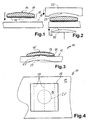
- FIGS. 1 to 3 show how a loose contact piece 13, which has a contact surface 14 and sits on a thin contact carrier 15 or is connected thereto, is placed on a contact support 19.
- a contact carrier 15 On the underside of the contact carrier 15 elongated welding webs 17 are formed. However, this is not mandatory, but can serve to improve the connection between the contact piece 13 and contact pad 19 shown in Fig. 2.
- the advantage of the welding webs 17 may also lie in the fact that a welding between them and a contact between the contact carriers 15 and contact pad 19 can not tear open or come off due to a welding at these regions projecting somewhat from the underside of the contact carrier 15.
- the contact piece 13 is placed on the contact pad 19.
- the connection is already made here or the two parts are welded together.
- a weld can either, as shown, substantially fix the weld bars 17 on the contact pad 19.
- a strong pressing can take place in such a way that there is a substantially full-area connection between contact piece 13 or contact carrier 15 and contact support 19, as shown in FIG. 3.
- Fig. 2 it is shown how from above a counter-system 22 is moved up to the contact piece 13.
- This counterplant 22 has a profile 23. This differs slightly from the shape of the contact surface 14 shown in Fig. 2, above all, it is more curved.
- the contact piece 13 is brought into the shape of this profile 23, as can be seen from Fig. 3.
- the impression 27 is made from below by the die 25 in the bottom of the contact pad 19.
- the profile 26 of the embossing die 25 is of importance here as well as that of the opposing abutment 22.
- the embossment 27 shown in FIG. 3 effects the underside of the contact pad 19.
- This embossment 27 generally corresponds exactly to the profile 26 of the embossing die 25.
- the profile 26 either has a shape matching the profile 23 of the counter-system or approximately the shape of a spherical surface.
- the indentation 27 'in the underside of the contact piece 13 is smaller than the indentation 27 from the surface extent.
- the indentation 27' is considerably smaller than the contact piece 13 from the surface extent It is thus achieved that the connection region between contact piece 13 or contact carrier 15 and upper side of contact support 19 remains the same around embossment 27 '. So it is made only a central impression, not the entire connection surface by arches. Nevertheless, it presses a total contact pad 19 and contact piece 13 together.
- FIG. 4 There, in the top view, it is easy to see to what extent the indentation 27 'shown in dashed lines is relatively small in area in the contact piece 13. This impression 27 'is also sufficient to deform the connection region between the contact piece 13 and the contact support 19 in the middle region such that the connection for the arrangement 11 of the contact piece 13 on the contact support 19 is strengthened or made stronger. It can also be seen here to what extent the indentation 27 'and thus also the indentation 27 passes through the stamping die 25 exactly through the center of the contact piece 13.
- a square or square contact piece 13 is shown. Of course, this could also be an arbitrarily designed contact piece, in particular a round contact piece. Whether the curvature of the contact surface 14 drops off equally on all sides, similar to a spherical surface or as an elongated curvature with the cross section recognizable in FIG. 1, likewise plays no role. In particular, a not inconsiderable deformation of the shape or the profile of the contact surface of the contact piece 13 can be made in the desired shape by the profile 23 of the counterpart 22.
- the contact connection 11 is formed as a so-called bimetal contact.
- the contact piece 13 in particular also the contact carrier 15, from a conventional contact material, in particular containing copper.
- the contact pad 19 is made of stainless steel.
- the welding of the contact carrier 13 with the contact pad can take place in the same machine as the introduction of the impression. In this case, effort can be saved.
Landscapes
- Engineering & Computer Science (AREA)
- Manufacturing & Machinery (AREA)
- Manufacture Of Switches (AREA)
- Coupling Device And Connection With Printed Circuit (AREA)
- Manufacturing Of Electrical Connectors (AREA)
- Contacts (AREA)
Abstract
Description
- Die Erfindung betrifft eine Verbindung eines Kontaktstückes auf einer Kontaktunterlage als Kontaktverbindung, wobei das Kontaktstück eine Kontaktoberfläche aufweist, an welche üblicherweise ein Gegenkontakt angelegt werden kann. Ebenso betrifft die Erfindung ein Verfahren zur Herstellung dieser Kontaktverbindung.
- Es ist bekannt, Kontaktstücke bzw. Kontaktköpfe auf Kontaktunterlagen aufzuschweißen. Dies erfolgt beispielsweise als Kontakte für elektromechanische Schaltgeräte, wie sie beispielsweise aus der
EP 898 291 A1 - Der Erfindung liegt die Aufgabe zugrunde, eine eingangs genannte Verbindung sowie ein Verfahren zur Herstellung einer solchen Verbindung zu schaffen, mit denen Probleme des Standes der Technik vermieden werden können, und insbesondere eine einfachere, sichere und dauerhafte Befestigung eines Kontaktstückes oder Kontaktkopfes auf einer Kontaktunterlage erreicht werden kann.
- Gelöst wird diese Aufgabe durch eine Verbindung mit den Merkmalen des Anspruchs 1 sowie ein Verfahren mit den Merkmalen des Anspruchs 10. Vorteilhafte sowie bevorzugte Ausgestaltungen der Erfindung sind Gegenstand der weiteren Ansprüche und werden im folgenden näher erläutert. Der Wortlaut der Ansprüche wird durch ausdrückliche Bezugnahme zum Inhalt der Beschreibung gemacht. Einige der nachfolgend beschriebenen Merkmale gelten sowohl für die Verbindung als auch für das Verfahren in allgemeiner Form, werden jedoch zur Vermeidung unnötiger Wiederholungen ohne Beschränkung dieser Allgemeingültigkeit nur einmal angeführt.
- Erfindungsgemäß ist vorgesehen, dass nach der Befestigung des Kontaktstückes auf der Kontaktunterlage eine Einprägung in die Kontaktunterlage von der anderen Seite her vorgenommen wird. Dies bedeutet also, dass das Kontaktstück zuerst in vorgegebener Position auf die Kontaktunterlage aufgesetzt wird und dort befestigt wird, insbesondere mit der endgültigen Befestigung. Anschließend wird die Einprägung in die Kontaktunterlage vorgenommen. Dies erfolgt derart, dass die Einprägung durch die gesamte Kontaktunterlage hindurchgeht und sich noch in das Kontaktstück hinein auswirkt, bzw. auch dieses geprägt, gestaucht bzw. verformt wird. Durch einen derartigen Prägevorgang nach dem Befestigen des Kontaktstückes auf der Kontaktunterlage wird diese Verbindung, insbesondere wenn es eine Schweißverbindung ist, noch verstärkt oder dauerhafter gemacht. Dies erfolgt zum Teil dadurch, dass das vorherige Verbinden oder Verschweißen zwischen Kontaktstück und Kontaktunterlage im wesentlichen ohne mechanische Spannungen erfolgt ist. Das Einprägen dagegen ruft durch die entstehende Verformung eine derartige Verspannung hervor, wodurch die gesamte Verbindung verfestigt und stabilisiert wird. Dies führt auch dazu, dass das Kontaktstück eine gebogene Form einnimmt, wodurch die äußeren Ränder heruntergedrückt werden und somit die Verbindung besser aufrechterhalten bleibt. Darüber hinaus wirkt die Einprägung als eine Art Formschluss zumindest gegen seitlich wirkende Kräfte. Auch dadurch wird die Verbindung stabiler.
- Die Einprägung kann dabei derart stark sein bzw. so ausgebildet sein, dass an einem ebenen Kontaktstück die Oberfläche konvex nach außen gewölbt wird. Ist das Kontaktstück bereits gewölbt, kann diese Wölbung noch konvex verstärkt werden. Vorteilhaft ist es während des Einprägens möglich, das Kontaktstück an einer Art Gegenlager anzusetzen, damit es nicht von der Kontaktunterlage abgelöst oder weggeschlagen werden kann. Besonders vorteilhaft ist ein Gegenlager derart mit einer gewünschten Form für das Kontaktstück versehen, dass die Oberfläche des Kontaktstückes sozusagen in diese Form hineingeschlagen wird und sie im wesentlichen annimmt bzw. sich ihr entsprechend verformt.
- Bei einer Ausbildung der Erfindung wird die Einprägung in etwa an der Stelle des Flächenmittelpunktes des Kontaktstückes vorgenommen. Vorteilhaft wird die Einprägung genau am Flächenmittelpunkt des Kontaktstückes eingebracht, um so eine entstehende Wölbung am Kontaktstück möglichst gleichmäßig und zentriert zu erstellen.
- Die Form der Einprägung ist vorteilhaft möglichst gleichmäßig, also zumindest achsensymmetrisch. Besonders vorteilhaft ist sie kreisrund und wird durch eine entsprechend abgerundete Prägespitze verursacht. Alternativ könnten auch mit kreuzförmigen Prägespitzen odgl. Einprägungen vorgenommen werden, welche dann zumindest im Material der Kontaktunterlage eine größere Einbringtiefe erreichen. Hierbei ist besonders vorteilhaft als Gegenanlage des Kontaktstückes ein der gewünschten Oberfläche des Kontaktstückes entsprechendes Gegenlager vorgesehen, damit sich die kreuzförmige Einprägung nicht an der Oberfläche störend auswirkt.
- Es wird als vorteilhaft angesehen, wenn die Wölbung derart eingeprägt wird, dass sie an der Fläche zwischen Kontaktunterlage und Kontaktstück kleiner ist als die Fläche des Kontaktstückes selber. Somit kann vor allem verhindert werden, dass das gesamte Kontaktstück auf einer Art sich erhebenden Wölbung sitzt. Des weiteren wird durch eine kleinere Fläche der Einprägung sichergestellt, dass die Wölbung in einem inneren Bereich des Kontaktstückes in das Kontaktstück hineingebracht wird. In dem umgebenden Bereich des Kontaktstückes findet dagegen keine Wölbung und somit auch keine Prägung statt. Vorteilhaft ist die Fläche der Wölbung erheblich kleiner als diejenige des Kontaktstückes, beispielsweise kann sie zwischen 20% und 50% betragen.
- Bei einer Ausgestaltung der Erfindung kann das Kontaktstück einen dünnen Kontaktträger aufweisen, mit dem es verbunden ist. Vorteilhaft ist diese Verbindung vollflächig, beispielsweise durch Verschweißen oder Aufeinanderwalzen der entsprechenden Materialien. Wird bei einer Anordnung von einem Kontaktstück an einem Kontaktträger, sozusagen als zweischichtiges Kontaktstück, jeweils ein unterschiedliches Material gewählt, so erhält man ein Bimetall-Kontaktstück. Beispielsweise kann hierzu der Kontaktträger aus Edelmetall bestehen oder Edelstahl. Das Kontaktstück wiederum kann aus einer Kupfer- bzw. Messinglegierung bestehen, insbesondere auch aus einer Sinter-Legierung. Der Vorteil solcher Bimetall-Kontaktstücke liegt darin, dass sie hinsichtlich der vorgesehenen Verbiegung so ausgelegt sein können, dass bei einer Erwärmung im Betrieb ein Verziehen des Kontaktstückes auf ungewollte Art vermieden wird. Insbesondere verformt sich dabei das Werkstück in eine bei hoher bzw. Betriebstemperatur vorliegende Endform, welche der eigentlich gewünschten entspricht. In dieser Form wird dann auch die mechanische Verbindung weniger beansprucht.
- In weiterer Ausgestaltung der Erfindung können an der Unterseite des Kontaktstückes oder des Kontaktträgers, jedenfalls an der Seite zur Anlage an der Kontaktunterlage, längliche Erhebungen vorgesehen sein. Diese können beispielsweise nach Art langgezogener Stege ausgebildet sein. Vorteilhaft verlaufen sie zumindest teilweise parallel zueinander und sind insbesondere auch gerade. Diese Stege sind mit einer leichten Erhöhung aus dem Material des Kontaktstückes oder des Kontaktträgers herausgeformt. Lediglich mit diesen Erhebungen erfolgt die Berührung bzw. der Kontakt zwischen Kontaktunterlage einerseits und Kontaktstück oder Kontaktträger andererseits. Eine Schweißverbindung zwischen Kontaktstück und Kontaktunterlage sieht vor allem eine direkte Verschweißung mittels dieser Stege auf der Kontaktunterlage vor. Durch die abstehenden Stege ist auch eine definierte, bzw. flächenmäßig und ortsmäßig genau vorgegebene Verbindung zwischen Kontaktstück und Kontaktunterlage möglich.
- Ein weiterer Vorteil derartiger Stege liegt darin, dass mit Ihnen eine Verschweißung auf der Kontaktunterlage noch besser erfolgen kann als mit einer planen Fläche, insbesondere definierter. Vor allem bei einer Kontaktschweißung wirkt sich das positiv aus. Hier kommt auch ein weiterer besonders positiver Effekt der Erfindung mit der Einprägung zum Tragen. Mit der Verschweißung über die vorgenannten Stege liegt eine relativ kleine Übergangsfläche zwischen Kontaktstück und Kontaktunterlage vor, also ein geringer elektrischer Widerstand und somit hohe Erwärmung bei elektrischem Kontakt. Dies ist nachteilig in vielfacher Hinsicht, insbesondere wegen Abnutzung des Kontaktes und auch Kontaktbrand. Darüber hinaus bewirkt eine starke Erwärmung eine Verformung des Kontaktstückes, die wiederum zu einem Ablösen führen kann. Die Einprägung schafft hier einen flächigen Kontakt zwischen Kontaktunterlage und Kontaktstück, also eine wesentlich vergrößerte Kontaktfläche, wodurch die vorgenannten Probleme nicht oder nur geringfügig auftreten.
- Diese und weitere Merkmale gehen außer aus den Ansprüchen auch aus der Beschreibung und den Zeichnungen hervor, wobei die einzelnen Merkmale jeweils für sich allein oder zu mehreren in Form von Unterkombinationen bei einer Ausführungsform der Erfindung und auf anderen Gebieten verwirklicht sein und vorteilhafte sowie für sich schutzfähige Ausführungen darstellen können, für die hier Schutz beansprucht wird. Die Unterteilung der Anmeldung in einzelne Abschnitte sowie Zwischen-Überschriften beschränken die unter diesen gemachten Aussagen nicht in ihrer Allgemeingültigkeit.
- Ausführungsbeispiele der Erfindung sind in den Zeichnungen schematisch dargestellt und werden im folgenden näher erläutert. In den Zeichnungen zeigt:
- Fig. 1
- einen Schnitt durch ein erfindungsgemäßes Kontaktstück mit zwei Schichten und parallelen Stegen an der Unterseite;
- Fig. 2
- eine Schnittdarstellung eines Kontaktstückes ähnlich Fig. 1, welches auf einer Kontaktunterlage sitzt und mit dieser verschweißt ist;
- Fig. 3
- eine Schnittdarstellung eines Kontaktstückes auf einer Kontaktunterlage ähnlich Fig. 2, wobei hier die Einprägung vorgenommen worden ist und
- Fig. 4
- eine Draufsicht auf die Anordnung aus Fig. 3 mit Verlauf der Schweißstege der dritten Anbringung der Vertiefung bzw. Einprägung an dem Kontaktstück.
- In den Fig. 1 bis 3 ist dargestellt, wie ein an sich loses Kontaktstück 13, welches eine Kontaktoberfläche 14 aufweist und auf einem dünnen Kontaktträger 15 sitzt bzw. mit diesem verbunden ist, auf eine Kontaktunterlage 19 aufgesetzt wird. An der Unterseite des Kontaktträgers 15 sind längliche Schweißstege 17 ausgebildet. Dies ist jedoch nicht zwingend, kann aber dazu dienen, die in Fig. 2 dargestellte Verbindung zwischen Kontaktstück 13 und Kontaktunterlage 19 zu verbessern. Der Vorteil der Schweißstege 17 kann auch darin liegen, dass durch eine Verschweißung an diesen etwas von der Unterseite des Kontaktträgers 15 abstehenden Bereichen eine dazwischen stattfindende Verformung zwischen Kontaktträgern 15 und Kontaktunterlage 19 eine Schweißverbindung nicht aufreißen bzw. ablösen kann.
- In Fig. 2 ist das Kontaktstück 13 auf die Kontaktunterlage 19 aufgesetzt. Insbesondere ist hier bereits die Verbindung vorgenommen bzw. sind die beiden Teile miteinander verschweißt. Eine Verschweißung kann entweder, wie dargestellt, im wesentlichen die Schweißstege 17 auf der Kontaktunterlage 19 befestigen. Alternativ kann eine starke Andrückung erfolgen derart, dass eine im wesentlichen vollflächige Verbindung zwischen Kontaktstück 13 bzw. Kontaktträger 15 und Kontaktunterlage 19 vorliegt, wie in Fig. 3 gezeigt ist.
- In Fig. 2 ist dargestellt, wie von oben eine Gegenanlage 22 an das Kontaktstück 13 herangefahren wird. Diese Gegenanlage 22 weist ein Profil 23 auf. Dieses weicht leicht von der in Fig. 2 noch dargestellten Form der Kontaktoberfläche 14 ab, vor allem ist es stärker gewölbt. Das Kontaktstück 13 wird in die Form dieses Profils 23 gebracht, wie aus Fig. 3 zu erkennen ist. Nach Heranfahren der Gegenanlage 22 an das Kontaktstück 13 wird von unten her die Einprägung 27 durch den Prägestempel 25 in die Unterseite der Kontaktunterlage 19 vorgenommen. Das Profil 26 des Prägestempels 25 ist hier ebenso von Bedeutung wie das der Gegenanlage 22. Es bewirkt die in Fig. 3 dargestellte Einprägung 27 in die Unterseite der Kontaktunterlage 19. Diese Einprägung 27 entspricht in der Regel exakt dem Profil 26 des Prägestempels 25. Vorteilhaft weist das Profil 26 entweder eine zu dem Profil 23 der Gegenanlage passende Form auf bzw. in etwa die Form einer Kugeloberfläche.
- Dabei ist auch zu erkennen, wie sich die Einprägung 27 als Einprägung 27' in die Unterseite des Kontaktstückes 13 durch den Kontaktträger 15 hindurch fortsetzt. Durch diesen Druck wird auch die Form des Kontaktstücks 13 bzw. das Profil 14' der Kontaktoberfläche an das Profil 23 der Gegenanlage 22 angepasst. Dabei ist die Wölbung der Kontaktoberfläche 14' stärker als diejenige der ursprünglichen Kontaktoberfläche 14. Dies kann jedoch im Voraus einkalkuliert werden, wenn es auf die genaue Form und Abmessungen des fertigen Kontaktes 11 ankommt.
- Es ist auch zu erkennen, dass die Einprägung 27' in die Unterseite des Kontaktstücks 13 hinein von der Flächenausdehnung her kleiner ist als die Einprägung 27. Insbesondere ist zu erkennen, dass die Einprägung 27' von der Flächenausdehnung her erheblich kleiner ist als das Kontaktstück 13. So wird erreicht, dass der Verbindungsbereich zwischen Kontaktstück 13 bzw. Kontaktträger 15 und Oberseite der Kontaktunterlage 19 um die Einprägung 27' herum gleich bleibt. Es wird also lediglich eine mittige Einprägung vorgenommen, die nicht die gesamte Verbindungsfläche durchwölbt. Dennoch drückt sie insgesamt Kontaktunterlage 19 und Kontaktstück 13 stärker zusammen.
- Darüber hinaus ist zu erkennen, dass die sehr geringe Kontaktfläche zwischen der Oberseite der Kontaktunterlage 19 und den Stegen 17 am Kontaktträger 15 in Fig. 3 stark vergrößert ist. Sie ist nämlich nicht mehr linienförmig gemäß der Stege 17, sondern im wesentlichen vollflächig.
- In diesem Zusammenhang wird auf Fig. 4 verwiesen. Dort ist in der Draufsicht gut zu erkennen, inwiefern die gestrichelt dargestellte Einprägung 27' in das Kontaktstück 13 hinein flächenmäßig relativ klein ist. Auch diese Einprägung 27' reicht aus, den Verbindungsbereich zwischen Kontaktstück 13 und Kontaktunterlage 19 im mittleren Bereich so zu verformen, dass die Verbindung für die Anordnung 11 des Kontaktstücks 13 an der Kontaktunterlage 19 gestärkt bzw. fester gemacht wird. Es ist hier auch zu erkennen, inwiefern die Einprägung 27' und somit auch die Einprägung 27 durch den Prägestempel 25 genau durch den Mittelpunkt des Kontaktstücks 13 verläuft.
- Zwar ist in Fig. 4 ein viereckiges bzw. quadratisches Kontaktstück 13 dargestellt. Selbstverständlich könnte dies auch ein beliebig ausgebildetes Kontaktstück sein, insbesondere auch ein rundes Kontaktstück. Ob die Wölbung der Kontaktoberfläche 14 zu allen Seiten hin gleich abfällt ähnlich einer Kugelfläche oder als langgestreckte Wölbung mit dem in Fig. 1 erkennbaren Querschnitt vorliegt, spielt ebenso keine Rolle. Insbesondere kann hier durch das Profil 23 der Gegenanlage 22 eine nicht unbeträchtliche Verformung der Form bzw. des Profils der Kontaktoberfläche des Kontaktstücks 13 in gewünschte Form erfolgen.
- Durch die Stabilisierung der Kontaktverbindung 11 aufgrund der Einprägung 27 und 27' sind Kontaktqualität und Kontaktlebensdauer verbessert.
- Des weiteren ist noch zu bemerken, dass die Kontaktverbindung 11 als sogenannter Bimetall-Kontakt ausgebildet ist. Dabei besteht das Kontaktstück 13, insbesondere auch der Kontaktträger 15, aus einem üblichen Kontaktmaterial, insbesondere Kupfer enthaltend. Die Kontaktunterlage 19 besteht aus Edelstahl.
- In einer Abwandlung des Herstellungsverfahrens nach den Fig. 1 bis 3 kann das Verschweißen des Kontaktträgers 13 mit der Kontaktunterlage in derselben Maschine erfolgen wie das Einbringen der Einprägung. In diesem Fall kann Aufwand eingespart werden.
Claims (13)
- Verbindung eines Kontaktstückes (13) mit Kontaktoberfläche (14) auf einer Kontaktunterlage (19), dadurch gekennzeichnet, dass nach der Befestigung des Kontaktstückes auf der Kontaktunterlage eine Einprägung in die Kontaktunterlage (19) von der anderen Seite her vorgenommen ist mit einer entsprechenden durchgehenden Einprägung (27) in das Kontaktstück (13) hinein.
- Verbindung nach Anspruch 1, dadurch gekennzeichnet, dass das Kontaktstück (13) an der Kontaktoberfläche (14) konvex gewölbt ist, wobei vorzugsweise die konvexe Wölbung durch die Einprägung (27) verstärkt ist (14').
- Verbindung nach Anspruch 1 oder 2, dadurch gekennzeichnet, dass das Kontaktstück (13) auf der Kontaktunterlage (19) festgeschweißt ist.
- Verbindung nach einem der vorhergehenden Ansprüche, dadurch gekennzeichnet, dass die Einprägung (27) in etwa, vorzugsweise genau, im Flächenmittelpunkt des Kontaktstückes (13) liegt.
- Verbindung nach einem der vorhergehenden Ansprüche, dadurch gekennzeichnet, dass die Einprägung (27) zumindest achsensymmetrisch ist, vorzugsweise quadratisch oder kreisrund.
- Verbindung nach einem der vorhergehenden Ansprüche, dadurch gekennzeichnet, dass die Fläche der eingeprägten Wölbung (27') an der Seite der Kontaktunterlage (19) zum Kontaktstück (13) hin kleiner ist als die Fläche des Kontaktstückes, insbesondere zwischen 20% und 50% der Fläche beträgt.
- Verbindung nach einem der vorhergehenden Ansprüche, dadurch gekennzeichnet, dass das Kontaktstück (13) mit einem dünnen Kontaktträger (15) verbunden ist, insbesondere vollflächig, und der Kontaktträger an der Kontaktunterlage (19) befestigt ist.
- Verbindung nach Anspruch 7, dadurch gekennzeichnet, dass an der Unterseite des Kontaktträgers (15) zur Kontaktunterlage (19) hin Erhebungen vorgesehen sind, vorzugsweise in Form paralleler und/oder langgezogener Stege (17), wobei insbesondere der Kontaktträger im wesentlichen mit den Stegen auf der Kontaktunterlage (19) aufliegt und befestigt ist.
- Verbindung nach einem der vorhergehenden Ansprüche, dadurch gekennzeichnet, dass das Kontaktstück (13) und der Kontaktträger (15) ein Bimetall bilden, wobei vorzugsweise der Kontaktträger aus Edelmetall besteht.
- Verfahren zur Herstellung einer Verbindung nach einem der vorhergehenden Ansprüche, gekennzeichnet durch die Schritte:- Bereitstellen des Kontaktstückes (13) und der Kontaktunterlage (19),- Aufsetzen des Kontaktstückes auf die Kontaktunterlage an der vorgesehenen Stelle,- Befestigen des Kontaktstückes auf der Kontaktunterlage,- Einbringen einer Einprägung (27) an die gegenüberliegende Seite der Kontaktunterlage im Bereich des Kontaktstückes.
- Verfahren nach Anspruchs 10, dadurch gekennzeichnet, dass die Achse der Einprägung (27) in etwa durch den Flächenmittelpunkt des Kontaktstückes (13) weist.
- Verfahren nach Anspruche 10 oder 11, dadurch gekennzeichnet, dass durch die Einprägung (27) das Kontaktstück (13) an einer Kontaktoberfläche (14) konvex nach außen gewölbt wird bzw. eine konvexe Wölbung nach außen verstärkt wird (14').
- Verfahren nach einem der Ansprüche 10 bis 12, dadurch gekennzeichnet, dass während des Prägevorganges das Kontaktstück (13) durch eine flächige, vorzugsweise im wesentlichen vollflächige, Gegenanlage (22) gehalten und insbesondere dadurch in seiner endgültigen Wölbung (14') geformt wird.
Priority Applications (2)
| Application Number | Priority Date | Filing Date | Title |
|---|---|---|---|
| PL06010028T PL1724799T3 (pl) | 2005-05-18 | 2006-05-16 | Elektryczne połączenie stykowe i sposób wytwarzania |
| SI200631126T SI1724799T1 (sl) | 2005-05-18 | 2006-05-16 | Električna kontaktna povezava in postopek izdelave |
Applications Claiming Priority (1)
| Application Number | Priority Date | Filing Date | Title |
|---|---|---|---|
| DE102005023722A DE102005023722A1 (de) | 2005-05-18 | 2005-05-18 | Elektrische Kontaktverbindung und Verfahren zur Herstellung |
Publications (3)
| Publication Number | Publication Date |
|---|---|
| EP1724799A2 true EP1724799A2 (de) | 2006-11-22 |
| EP1724799A3 EP1724799A3 (de) | 2008-03-19 |
| EP1724799B1 EP1724799B1 (de) | 2011-07-06 |
Family
ID=36809136
Family Applications (1)
| Application Number | Title | Priority Date | Filing Date |
|---|---|---|---|
| EP06010028A Expired - Lifetime EP1724799B1 (de) | 2005-05-18 | 2006-05-16 | Elektrische Kontaktverbindung und Verfahren zur Herstellung |
Country Status (6)
| Country | Link |
|---|---|
| EP (1) | EP1724799B1 (de) |
| AT (1) | ATE515783T1 (de) |
| DE (1) | DE102005023722A1 (de) |
| ES (1) | ES2369275T3 (de) |
| PL (1) | PL1724799T3 (de) |
| SI (1) | SI1724799T1 (de) |
Citations (1)
| Publication number | Priority date | Publication date | Assignee | Title |
|---|---|---|---|---|
| US4357751A (en) | 1979-11-06 | 1982-11-09 | Fuji Electric Co., Ltd. | Electrical contact manufacturing method and apparatus |
Family Cites Families (8)
| Publication number | Priority date | Publication date | Assignee | Title |
|---|---|---|---|---|
| DE643960C (de) * | 1933-09-10 | 1937-04-21 | Stotz Kontakt Gmbh | Bimetallstreifen, der nur aus Komponenten schlechter Waermeleitfaehigkeit besteht und bei mittelbar von aussen erfolgender Erwaermung durch Ausbiegen wirksam wird |
| US3258830A (en) * | 1964-02-28 | 1966-07-05 | Albert F Pityo | Method of producing an electrical contact assembly |
| GB1269559A (en) * | 1968-05-08 | 1972-04-06 | United Carr Inc | Method of forming an electrical contact |
| DE4040245C2 (de) * | 1990-12-15 | 2001-02-22 | Teves Gmbh Alfred | Kontaktanordnung für elektrische Schalter, insbesondere für Kraftfahrzeuge |
| DE9206669U1 (de) * | 1992-05-20 | 1992-07-30 | Doduco GmbH + Co Dr. Eugen Dürrwächter i.K., 75181 Pforzheim | Kontaktfeder für Schwachstromanwendungen |
| DE19736308A1 (de) * | 1997-08-21 | 1999-02-25 | Ego Elektro Geraetebau Gmbh | Leistungssteuergerät |
| DE19748288A1 (de) * | 1997-10-31 | 1999-05-06 | Kloeckner Moeller Gmbh | Schaltkontaktstück für Niederspannungs-Schaltgeräte |
| DE19809450A1 (de) * | 1998-03-06 | 1999-09-23 | Inovan Stroebe | Elektrisches Mehrlagen-Kontaktprofil |
-
2005
- 2005-05-18 DE DE102005023722A patent/DE102005023722A1/de not_active Withdrawn
-
2006
- 2006-05-16 AT AT06010028T patent/ATE515783T1/de active
- 2006-05-16 EP EP06010028A patent/EP1724799B1/de not_active Expired - Lifetime
- 2006-05-16 SI SI200631126T patent/SI1724799T1/sl unknown
- 2006-05-16 ES ES06010028T patent/ES2369275T3/es not_active Expired - Lifetime
- 2006-05-16 PL PL06010028T patent/PL1724799T3/pl unknown
Patent Citations (1)
| Publication number | Priority date | Publication date | Assignee | Title |
|---|---|---|---|---|
| US4357751A (en) | 1979-11-06 | 1982-11-09 | Fuji Electric Co., Ltd. | Electrical contact manufacturing method and apparatus |
Also Published As
| Publication number | Publication date |
|---|---|
| EP1724799B1 (de) | 2011-07-06 |
| SI1724799T1 (sl) | 2011-11-30 |
| ATE515783T1 (de) | 2011-07-15 |
| PL1724799T3 (pl) | 2011-11-30 |
| EP1724799A3 (de) | 2008-03-19 |
| ES2369275T3 (es) | 2011-11-29 |
| DE102005023722A1 (de) | 2006-11-23 |
Similar Documents
| Publication | Publication Date | Title |
|---|---|---|
| EP1207313B1 (de) | Mutter und Verfahren zu ihrer Herstellung | |
| AT508455A1 (de) | Presse zur herstellung eines tampons | |
| EP0790426B1 (de) | Verfahren zum Herstellen einer ebenen Reiblamelle | |
| EP0934132B1 (de) | Durchsetzfügeverfahren und -vorrichtung zum verbinden von blechteilen | |
| AT506031B1 (de) | Sägekette | |
| DE918090C (de) | Verbinden von mindestens zum Teil geradlinig verlaufenden Teilen | |
| EP2047530A1 (de) | Federelement sowie piezoaktor mit dem federelement | |
| DE102009003655A1 (de) | Blechplatine mit homogenem Dickenübergang | |
| EP1724799B1 (de) | Elektrische Kontaktverbindung und Verfahren zur Herstellung | |
| EP2978546B1 (de) | Biegewerkzeuge zum vorbiegen und zudrücken | |
| EP2457674B1 (de) | Spulenanordnung für das elektromagnetische Umformen und/oder Schneiden mit einem Treibblech | |
| AT389958B (de) | Relais | |
| DE102011015219B4 (de) | Verlötbare Elektrode und Verfahren zur Herstellung einer verlötbaren Elektrode | |
| DE102004054868A1 (de) | Stanzvorrichtung | |
| DE3008342C2 (de) | Verfahren zur Vergütung von Metallflachfedern | |
| EP3739153B1 (de) | Schliesszylinderschlüssel und verfahren zu dessen herstellung | |
| EP2145707B1 (de) | Flachstab oder Flachprofilstab aus Metall | |
| DE19742781C2 (de) | Verfahren und Vorrichtung zum Stanzen wenigstens einer Öffnung in ein Teil mit winkelförmigem Querschnitt | |
| DE202004009138U1 (de) | Stanzeinrichtung und Stanzstempel für diese | |
| DE102010016555B4 (de) | Verfahren zur Fertigung eines Werkstückes durch Umformen, sowie Fertigungseinrichtung mit einem Biegewerkzeug für eine Blechbiegepresse | |
| DE19640119C2 (de) | Biegewerkzeug | |
| DE102004002844B3 (de) | Einpressvorrichtung zur Bearbeitung vorgeformter Bauteile | |
| EP2163794A1 (de) | Dichtungsring mit einem ringförmigen metallischen Träger sowie Verfahren zur Herstellung eines Dichtungsring | |
| WO2002084131A1 (de) | Verfahren zum anbringen eines funktionselements in form eines gewindestifts in ein blechteil | |
| DE912716C (de) | Elastische, metallische Blattfeder fuer elektrische Schaltgeraete |
Legal Events
| Date | Code | Title | Description |
|---|---|---|---|
| PUAI | Public reference made under article 153(3) epc to a published international application that has entered the european phase |
Free format text: ORIGINAL CODE: 0009012 |
|
| AK | Designated contracting states |
Kind code of ref document: A2 Designated state(s): AT BE BG CH CY CZ DE DK EE ES FI FR GB GR HU IE IS IT LI LT LU LV MC NL PL PT RO SE SI SK TR |
|
| AX | Request for extension of the european patent |
Extension state: AL BA HR MK YU |
|
| PUAL | Search report despatched |
Free format text: ORIGINAL CODE: 0009013 |
|
| AK | Designated contracting states |
Kind code of ref document: A3 Designated state(s): AT BE BG CH CY CZ DE DK EE ES FI FR GB GR HU IE IS IT LI LT LU LV MC NL PL PT RO SE SI SK TR |
|
| AX | Request for extension of the european patent |
Extension state: AL BA HR MK YU |
|
| 17P | Request for examination filed |
Effective date: 20080423 |
|
| 17Q | First examination report despatched |
Effective date: 20080702 |
|
| AKX | Designation fees paid |
Designated state(s): AT BE BG CH CY CZ DE DK EE ES FI FR GB GR HU IE IS IT LI LT LU LV MC NL PL PT RO SE SI SK TR |
|
| GRAP | Despatch of communication of intention to grant a patent |
Free format text: ORIGINAL CODE: EPIDOSNIGR1 |
|
| GRAS | Grant fee paid |
Free format text: ORIGINAL CODE: EPIDOSNIGR3 |
|
| GRAA | (expected) grant |
Free format text: ORIGINAL CODE: 0009210 |
|
| AK | Designated contracting states |
Kind code of ref document: B1 Designated state(s): AT BE BG CH CY CZ DE DK EE ES FI FR GB GR HU IE IS IT LI LT LU LV MC NL PL PT RO SE SI SK TR |
|
| REG | Reference to a national code |
Ref country code: GB Ref legal event code: FG4D Free format text: NOT ENGLISH |
|
| REG | Reference to a national code |
Ref country code: CH Ref legal event code: EP |
|
| REG | Reference to a national code |
Ref country code: IE Ref legal event code: FG4D Free format text: LANGUAGE OF EP DOCUMENT: GERMAN |
|
| REG | Reference to a national code |
Ref country code: DE Ref legal event code: R096 Ref document number: 502006009782 Country of ref document: DE Effective date: 20110901 |
|
| REG | Reference to a national code |
Ref country code: RO Ref legal event code: EPE |
|
| REG | Reference to a national code |
Ref country code: NL Ref legal event code: VDEP Effective date: 20110706 |
|
| REG | Reference to a national code |
Ref country code: ES Ref legal event code: FG2A Ref document number: 2369275 Country of ref document: ES Kind code of ref document: T3 Effective date: 20111129 |
|
| REG | Reference to a national code |
Ref country code: PL Ref legal event code: T3 |
|
| PG25 | Lapsed in a contracting state [announced via postgrant information from national office to epo] |
Ref country code: IS Free format text: LAPSE BECAUSE OF FAILURE TO SUBMIT A TRANSLATION OF THE DESCRIPTION OR TO PAY THE FEE WITHIN THE PRESCRIBED TIME-LIMIT Effective date: 20111106 Ref country code: FI Free format text: LAPSE BECAUSE OF FAILURE TO SUBMIT A TRANSLATION OF THE DESCRIPTION OR TO PAY THE FEE WITHIN THE PRESCRIBED TIME-LIMIT Effective date: 20110706 Ref country code: PT Free format text: LAPSE BECAUSE OF FAILURE TO SUBMIT A TRANSLATION OF THE DESCRIPTION OR TO PAY THE FEE WITHIN THE PRESCRIBED TIME-LIMIT Effective date: 20111107 Ref country code: LT Free format text: LAPSE BECAUSE OF FAILURE TO SUBMIT A TRANSLATION OF THE DESCRIPTION OR TO PAY THE FEE WITHIN THE PRESCRIBED TIME-LIMIT Effective date: 20110706 Ref country code: NL Free format text: LAPSE BECAUSE OF FAILURE TO SUBMIT A TRANSLATION OF THE DESCRIPTION OR TO PAY THE FEE WITHIN THE PRESCRIBED TIME-LIMIT Effective date: 20110706 Ref country code: SE Free format text: LAPSE BECAUSE OF FAILURE TO SUBMIT A TRANSLATION OF THE DESCRIPTION OR TO PAY THE FEE WITHIN THE PRESCRIBED TIME-LIMIT Effective date: 20110706 |
|
| REG | Reference to a national code |
Ref country code: IE Ref legal event code: FD4D |
|
| PG25 | Lapsed in a contracting state [announced via postgrant information from national office to epo] |
Ref country code: LV Free format text: LAPSE BECAUSE OF FAILURE TO SUBMIT A TRANSLATION OF THE DESCRIPTION OR TO PAY THE FEE WITHIN THE PRESCRIBED TIME-LIMIT Effective date: 20110706 Ref country code: GR Free format text: LAPSE BECAUSE OF FAILURE TO SUBMIT A TRANSLATION OF THE DESCRIPTION OR TO PAY THE FEE WITHIN THE PRESCRIBED TIME-LIMIT Effective date: 20111007 Ref country code: CY Free format text: LAPSE BECAUSE OF FAILURE TO SUBMIT A TRANSLATION OF THE DESCRIPTION OR TO PAY THE FEE WITHIN THE PRESCRIBED TIME-LIMIT Effective date: 20110706 |
|
| PG25 | Lapsed in a contracting state [announced via postgrant information from national office to epo] |
Ref country code: SK Free format text: LAPSE BECAUSE OF FAILURE TO SUBMIT A TRANSLATION OF THE DESCRIPTION OR TO PAY THE FEE WITHIN THE PRESCRIBED TIME-LIMIT Effective date: 20110706 Ref country code: IE Free format text: LAPSE BECAUSE OF FAILURE TO SUBMIT A TRANSLATION OF THE DESCRIPTION OR TO PAY THE FEE WITHIN THE PRESCRIBED TIME-LIMIT Effective date: 20110706 Ref country code: CZ Free format text: LAPSE BECAUSE OF FAILURE TO SUBMIT A TRANSLATION OF THE DESCRIPTION OR TO PAY THE FEE WITHIN THE PRESCRIBED TIME-LIMIT Effective date: 20110706 |
|
| PLBE | No opposition filed within time limit |
Free format text: ORIGINAL CODE: 0009261 |
|
| STAA | Information on the status of an ep patent application or granted ep patent |
Free format text: STATUS: NO OPPOSITION FILED WITHIN TIME LIMIT |
|
| PG25 | Lapsed in a contracting state [announced via postgrant information from national office to epo] |
Ref country code: EE Free format text: LAPSE BECAUSE OF FAILURE TO SUBMIT A TRANSLATION OF THE DESCRIPTION OR TO PAY THE FEE WITHIN THE PRESCRIBED TIME-LIMIT Effective date: 20110706 |
|
| 26N | No opposition filed |
Effective date: 20120411 |
|
| PG25 | Lapsed in a contracting state [announced via postgrant information from national office to epo] |
Ref country code: DK Free format text: LAPSE BECAUSE OF FAILURE TO SUBMIT A TRANSLATION OF THE DESCRIPTION OR TO PAY THE FEE WITHIN THE PRESCRIBED TIME-LIMIT Effective date: 20110706 |
|
| REG | Reference to a national code |
Ref country code: DE Ref legal event code: R097 Ref document number: 502006009782 Country of ref document: DE Effective date: 20120411 |
|
| BERE | Be: lapsed |
Owner name: E.G.O. ELEKTRO-GERATEBAU G.M.B.H. Effective date: 20120531 |
|
| PG25 | Lapsed in a contracting state [announced via postgrant information from national office to epo] |
Ref country code: MC Free format text: LAPSE BECAUSE OF NON-PAYMENT OF DUE FEES Effective date: 20120531 |
|
| PGFP | Annual fee paid to national office [announced via postgrant information from national office to epo] |
Ref country code: ES Payment date: 20120525 Year of fee payment: 7 |
|
| REG | Reference to a national code |
Ref country code: CH Ref legal event code: PL |
|
| PG25 | Lapsed in a contracting state [announced via postgrant information from national office to epo] |
Ref country code: CH Free format text: LAPSE BECAUSE OF NON-PAYMENT OF DUE FEES Effective date: 20120531 Ref country code: LI Free format text: LAPSE BECAUSE OF NON-PAYMENT OF DUE FEES Effective date: 20120531 |
|
| PG25 | Lapsed in a contracting state [announced via postgrant information from national office to epo] |
Ref country code: BE Free format text: LAPSE BECAUSE OF NON-PAYMENT OF DUE FEES Effective date: 20120531 |
|
| REG | Reference to a national code |
Ref country code: FR Ref legal event code: ST Effective date: 20130131 |
|
| PG25 | Lapsed in a contracting state [announced via postgrant information from national office to epo] |
Ref country code: FR Free format text: LAPSE BECAUSE OF NON-PAYMENT OF DUE FEES Effective date: 20120531 |
|
| PG25 | Lapsed in a contracting state [announced via postgrant information from national office to epo] |
Ref country code: BG Free format text: LAPSE BECAUSE OF FAILURE TO SUBMIT A TRANSLATION OF THE DESCRIPTION OR TO PAY THE FEE WITHIN THE PRESCRIBED TIME-LIMIT Effective date: 20111006 |
|
| REG | Reference to a national code |
Ref country code: AT Ref legal event code: MM01 Ref document number: 515783 Country of ref document: AT Kind code of ref document: T Effective date: 20120516 |
|
| PG25 | Lapsed in a contracting state [announced via postgrant information from national office to epo] |
Ref country code: AT Free format text: LAPSE BECAUSE OF NON-PAYMENT OF DUE FEES Effective date: 20120516 |
|
| PGFP | Annual fee paid to national office [announced via postgrant information from national office to epo] |
Ref country code: GB Payment date: 20130522 Year of fee payment: 8 Ref country code: DE Payment date: 20130524 Year of fee payment: 8 |
|
| PGFP | Annual fee paid to national office [announced via postgrant information from national office to epo] |
Ref country code: SI Payment date: 20130508 Year of fee payment: 8 Ref country code: PL Payment date: 20130415 Year of fee payment: 8 Ref country code: IT Payment date: 20130523 Year of fee payment: 8 Ref country code: TR Payment date: 20130506 Year of fee payment: 8 Ref country code: RO Payment date: 20130510 Year of fee payment: 8 |
|
| PG25 | Lapsed in a contracting state [announced via postgrant information from national office to epo] |
Ref country code: LU Free format text: LAPSE BECAUSE OF NON-PAYMENT OF DUE FEES Effective date: 20120516 |
|
| PG25 | Lapsed in a contracting state [announced via postgrant information from national office to epo] |
Ref country code: HU Free format text: LAPSE BECAUSE OF FAILURE TO SUBMIT A TRANSLATION OF THE DESCRIPTION OR TO PAY THE FEE WITHIN THE PRESCRIBED TIME-LIMIT Effective date: 20060516 |
|
| REG | Reference to a national code |
Ref country code: DE Ref legal event code: R119 Ref document number: 502006009782 Country of ref document: DE |
|
| GBPC | Gb: european patent ceased through non-payment of renewal fee |
Effective date: 20140516 |
|
| PG25 | Lapsed in a contracting state [announced via postgrant information from national office to epo] |
Ref country code: RO Free format text: LAPSE BECAUSE OF NON-PAYMENT OF DUE FEES Effective date: 20140516 |
|
| PG25 | Lapsed in a contracting state [announced via postgrant information from national office to epo] |
Ref country code: SI Free format text: LAPSE BECAUSE OF NON-PAYMENT OF DUE FEES Effective date: 20140517 |
|
| REG | Reference to a national code |
Ref country code: SI Ref legal event code: KO00 Effective date: 20150106 |
|
| REG | Reference to a national code |
Ref country code: DE Ref legal event code: R119 Ref document number: 502006009782 Country of ref document: DE Effective date: 20141202 |
|
| PG25 | Lapsed in a contracting state [announced via postgrant information from national office to epo] |
Ref country code: IT Free format text: LAPSE BECAUSE OF NON-PAYMENT OF DUE FEES Effective date: 20140516 Ref country code: DE Free format text: LAPSE BECAUSE OF NON-PAYMENT OF DUE FEES Effective date: 20141202 |
|
| PG25 | Lapsed in a contracting state [announced via postgrant information from national office to epo] |
Ref country code: GB Free format text: LAPSE BECAUSE OF NON-PAYMENT OF DUE FEES Effective date: 20140516 |
|
| PG25 | Lapsed in a contracting state [announced via postgrant information from national office to epo] |
Ref country code: PL Free format text: LAPSE BECAUSE OF NON-PAYMENT OF DUE FEES Effective date: 20140516 |
|
| REG | Reference to a national code |
Ref country code: ES Ref legal event code: FD2A Effective date: 20150831 Ref country code: PL Ref legal event code: LAPE |
|
| PG25 | Lapsed in a contracting state [announced via postgrant information from national office to epo] |
Ref country code: ES Free format text: LAPSE BECAUSE OF NON-PAYMENT OF DUE FEES Effective date: 20140517 |
|
| PG25 | Lapsed in a contracting state [announced via postgrant information from national office to epo] |
Ref country code: TR Free format text: LAPSE BECAUSE OF NON-PAYMENT OF DUE FEES Effective date: 20140516 |