EP1724397B1 - Verfahren und vorrichtung um schienenwegparametern zu messen - Google Patents
Verfahren und vorrichtung um schienenwegparametern zu messen Download PDFInfo
- Publication number
- EP1724397B1 EP1724397B1 EP06114216A EP06114216A EP1724397B1 EP 1724397 B1 EP1724397 B1 EP 1724397B1 EP 06114216 A EP06114216 A EP 06114216A EP 06114216 A EP06114216 A EP 06114216A EP 1724397 B1 EP1724397 B1 EP 1724397B1
- Authority
- EP
- European Patent Office
- Prior art keywords
- main body
- measuring
- track
- respect
- telemetry
- Prior art date
- Legal status (The legal status is an assumption and is not a legal conclusion. Google has not performed a legal analysis and makes no representation as to the accuracy of the status listed.)
- Not-in-force
Links
- 238000000034 method Methods 0.000 title claims abstract description 11
- 238000006073 displacement reaction Methods 0.000 claims description 6
- 230000003287 optical effect Effects 0.000 claims 2
- 238000007689 inspection Methods 0.000 description 3
- 238000010276 construction Methods 0.000 description 2
- 230000003137 locomotive effect Effects 0.000 description 2
- 238000005259 measurement Methods 0.000 description 2
- 230000000694 effects Effects 0.000 description 1
- 238000009434 installation Methods 0.000 description 1
Images
Classifications
-
- B—PERFORMING OPERATIONS; TRANSPORTING
- B60—VEHICLES IN GENERAL
- B60M—POWER SUPPLY LINES, AND DEVICES ALONG RAILS, FOR ELECTRICALLY- PROPELLED VEHICLES
- B60M1/00—Power supply lines for contact with collector on vehicle
- B60M1/12—Trolley lines; Accessories therefor
- B60M1/28—Manufacturing or repairing trolley lines
-
- E—FIXED CONSTRUCTIONS
- E01—CONSTRUCTION OF ROADS, RAILWAYS, OR BRIDGES
- E01B—PERMANENT WAY; PERMANENT-WAY TOOLS; MACHINES FOR MAKING RAILWAYS OF ALL KINDS
- E01B35/00—Applications of measuring apparatus or devices for track-building purposes
- E01B35/02—Applications of measuring apparatus or devices for track-building purposes for spacing, for cross levelling; for laying-out curves
Definitions
- the present invention relates to a method and device for measuring railway line parameters and, more precisely, a method and a template for measuring and storing railway line parameters with the purpose of supplying such parameters to further railway line measuring devices.
- US 4,691,565 One example of known measuring device for railways is shown in US 4,691,565 .
- the US prior art document discloses a mobile machine comprising a satellite bogie preceding the measuring machine and communicating by means of laser beam, the machine being suitable to move on a railway in order to measure vertical and lateral position of the track. In such a way, the deviations of the track position determined by the measuring machine can be established and correction effected accordingly.
- a device for measuring the aforesaid line parameters affecting said operations is therefore needed, both for initial surveying during railway line construction and for periodical in-service inspections.
- Another object of the present invention to provide a device for measuring railway line parameters which is reliable, easy to use and, above all, streamline and robust.
- the object of the invention is therefore a railway line parameter measuring device according to claim 1.
- the object of the invention is a measuring method of said railway line parameters according to claim 7.
- the device of the present invention has the following main advantages.
- the first advantage is in that, after measuring such parameters, the devices needed for installing the cross arms and the line wires within the accepted tolerance limits can be calibrated and arranged.
- Another advantage resides in that the device allows to measure the aforesaid parameters in periodical in-service inspections.
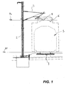
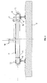
- a railway line comprises one or more tracks 1, several supporting posts 2, each of which presents a cross arm 3 for one or more carrying cables and one or more electrical contact wires 4.
- the plane on which the contact wire 4 lays is called “contact level” PC, while the plane on which the tracks 1 lays is called “track level” PF. Furthermore, the dotted line outlines the overall dimensions of a locomotive 5 provided with pantograph 6, the latter installed on the upper part of the locomotive and having the function of taking electrical energy from the service line via electrical contact with the contact wire 4.
- Figure 2 shows a perspective view of the railway line parameter measuring device of the present invention.
- the device comprises a main body 10 which is boxed and essentially shaped as an elongated parallelepiped.
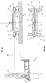
- a supporting plate 11 is slidingly mounted on a first end of the main body 10, the plate presenting a pair of protruding reference members such as locator pins 12.
- Each locator pin 12 is placed to abuttingly make contact with the surface contained on the inner plane of a rail of a track 1 (shown more in detail below).
- a second sliding plate 11 fitting at least one locator pin 12 for contact on the track 1 is envisaged.
- the second plate 11 also slides with respect to the main body 10.
- Both plates 11 can be actuated by a handwheel 13 (one for each plate 11, of which only one is shown in the figure) rotationally mounted on the end of the main body 10.
- the assembly formed by the plates 11 and the respective handwheels 13 is connected to a single worm screw or rack crossing through the main body 10 and integrally joining the two handwheels 13 so as to synchronise the displacement of the plates 11 reciprocally away or towards each other.
- a first telemetry device which comprises a light ray telemeter 14, while on the opposite plate 11 is rotationally mounted a light ray reference plaque 15.
- the plaque 15 according to its position either intercepts or lets through the light ray from the telemetry device 14 (this will be explained in better detail below).
- a second telemetry device 16 is present at the upper part of the main body 10.
- the second telemetry device 16 is slidingly mounted on a plate 17, the latter integral with the main body 10. More precisely, the second telemetry device 16 is mounted on a supporting bracket 18 which is slidingly engaged by a guide 19 integral with the plate 17. Furthermore, the plate 17 comprises a graduated ruler 20 parallel to the guide 19.
- a third telemetry device 21 arranged so as to measure with its ray the exact position of the bracket 18, and therefore of the second telemetry device 16, with respect to the main body 10 (illustrated in better detail below).
- bracket 18 presents an indicator integral with the latter which cooperates with the graduated scale of the ruler 20 during the displacement of the bracket 18, indicating on the graduated scale the relative position (illustrated in better detail below).
- the device 10 in order to measure the railway parameters the device 10 is firstly positioned on the rails of the track 1 to be measured.
- the handwheels 13 are then turned and, being mechanically connected, make both plates 11 synchronously move in/out. In this way, the locator pins 12 of the device come into contact with the inner plane of the track 1. Furthermore, by moving together, the locator pins 12 maintain the measuring device always centred with respect to the track 1, regardless of the gauge of the track 1 itself.
- the device for measuring the inclination/angle 22 on the main body 10 allows to measure the transversal inclination/angle of track 1.
- DR so-called the distance between the track and the supporting post 2 of the electrical wire 4.
- the first laser ray telemetry device 14 is mounted on plate 11 which in turn moves the locator pins 12. Therefore, once the pins 12 are tightened so as to stably position the device 10 according to the present invention on the track 1, the rotational plate 15 on which the other mobile plate 11 is mounted is turned.
- the light ray from the telemetry device 14 is intercepted by the rotational plate 15 and "measures" the distance between the two plates 11. Such measurement, given a constant which depends on the exact assembly point, allows to know the gauge of the track 1.
- the plate 15 is turned again so that the light ray from the telemetry device 14 intercepts the post 2, thus measuring the distance between pin 12 and face of the post 2.
- the measured gauge must be subtracted from such value and the result is multiplied by the cosine of the angle measured by the device 22.
- the product of such trigonometric operation is the "DR" measure, i.e. the distance between the track 1 and the post 2.
- the telemetry device 16 is then positioned so that the red spot of the light ray appears on the centre line of the contact wire 4. Such reading indicates the height of the wire 4 from the track level PF.
- the position of the bracket 18 carrying the device 16 is measured by means of the ray from the telemetry device 21 by maintaining stationary the ray on the wire 4 related to the device 16.
- the management and control of all the devices indicated above, such as the telemetry devices 14, 16 and 21, the inclination/angle measuring device 22 and the other accessory parts may be integrated with a data recorder unit (e.g., a PLC or similar) and all values may thus be stored automatically and transferred to a PC or similar.
- a data recorder unit e.g., a PLC or similar
- the reading of the aforesaid line parameters may be subsequently stored in a digital archive or via an appropriate data processing unit, for the purpose of generating a database of measured data/parameters with which it is possible to:
Landscapes
- Engineering & Computer Science (AREA)
- Manufacturing & Machinery (AREA)
- Mechanical Engineering (AREA)
- Architecture (AREA)
- Civil Engineering (AREA)
- Structural Engineering (AREA)
- Arrangements For Transmission Of Measured Signals (AREA)
- Length Measuring Devices By Optical Means (AREA)
- Machines For Laying And Maintaining Railways (AREA)
- Length Measuring Devices With Unspecified Measuring Means (AREA)
- Train Traffic Observation, Control, And Security (AREA)
- Measuring Pulse, Heart Rate, Blood Pressure Or Blood Flow (AREA)
- Measurement And Recording Of Electrical Phenomena And Electrical Characteristics Of The Living Body (AREA)
- A Measuring Device Byusing Mechanical Method (AREA)
Claims (9)
- Bahnlinienparametermesseinrichtung (10), wobei die Bahnlinie zwei oder mehr Gleise (1) auf einem Streckenniveau (PF) und eine Vielzahl von Unterstützungspfosten (2) für elektrische Kontaktdrähte (4) auf einem Kontaktniveau (PC) umfasst,
die Einrichtung umfasst:- einen länglichen Hauptkörper (10);- Befestigungsmittel (11, 12, 13) des Hauptkörpers (10) zum Befestigen auf dem Gleis;- Messmittel (14, 15), die integral an dem Befestigungsmittel (11) angebracht sind, so dass sie dessen Verschiebung in Bezug auf den Hauptkörper (10) in einer Richtung folgen, die im Wesentlichen parallel zur Längsrichtung des Hauptkörpers (10) ist;dadurch gekennzeichnet, dass
die ersten Messmittel Telemetriemittel sind, und dass die Einrichtung ferner zweite Telemetriemittel (16) umfasst, wobei die ersten Telemetriemittel eine Platte (15) umfassen, die an einem zweiten Ende des Hauptkörpers (10) in einer schwenkbaren Weise angebracht sind, wobei die Anordnung derart ausgestaltet ist, dass die Platte (15) aus einem ersten Zustand, bei der sie den Lichtstrahl unterbricht, der aus der Telemetrieeinrichtung (14) kommt, in einen zweiten Zustand bewegbar ist, in dem die Platte (15) in Bezug auf den Hauptkörper (10) gedreht ist und den Lichtstrahl nicht unterbricht, der aus der Telemetrieeinrichtung (14) kommt, und wobei die zweiten Telemetriemittel (16) eine Unterstützungsplatte (17), die fest an dem Hauptkörper (10) angebracht ist und eine Führung (19) aufweist, und einen Lichtsrahltelemeter (16) umfassen, der eine Ausrichtung aufweist, die im Wesentlichen orthogonal in Bezug auf die Längsrichtung des Hauptkörpers (10) ist, und der an einem Unterstützungsausleger (18) des Telemeters (16) angebracht ist, wobei der Unterstützungsausleger (18) mit der Führung (19) derart kooperiert, dass der Telemeter (16) in einer gleitenden Weise in Bezug auf den Hauptkörper (10) gestützt wird. - Bahnlinienparametermesseinrichtung (10) nach Anspruch 1, bei der der Hauptkörper (10) aus einem oder mehreren Behälterelementen besteht.
- Bahnlinienparametermesseinrichtung (10) nach Anspruch 1 oder 2, bei der die Befestigungsmittel ferner umfassen:- zumindest eine Platte (11), die in einer gleitenden Weise an dem Hauptkörper (10) und an dem seinem ersten Ende angebracht ist;- zumindest ein Halteelement (12), das integral auf der Platte (11) angebracht ist, zum Kooperieren in einer anstoßenden Weise mit einem vorbestimmten Oberflächenpunkt an dem Gleis (1) der Strecke; und- zumindest ein Auslöseelement (13) zum Verschieben der zumindest einen Platte (11) in Beug mit dem Hauptkörper (10).
- Bahnlinienparametermesseinrichtung (10) nach einem der vorhergehenden Ansprüche, bei der die Platte (17) ebenfalls einen abgestuften Regler (20), der in einer parallelen Weise zur Führung (19) angeordnet ist, und einen mit dem Ausleger (18) integralen Anzeiger (23) zum Kooperieren mit dem abgestuften Regler (20) umfasst.
- Bahnlinienparametermesseinrichtung (10) nach einem der vorhergehenden Ansprüche, die ferner dritte Telemetriemittel (21) umfasst, die integral mit dem Hauptkörper (10) angeordnet sind, und die zum Messen der Verschiebung der zweiten Telemetriemittel (16) in Bezug auf die Längsrichtung des Hauptkörpers vorgesehen sind.
- Bahnlinienparametermesseinrichtung (10) nach einem oder mehreren der vorhergehenden Ansprüche, die ferner Mittel zum Messen der Neigung/des Winkels des Hauptkörpers (10) in Bezug auf die vertikale Gravitationsrichtung umfasst.
- Bahnlinienparametermessverfahren, wobei die Bahnlinie zwei oder mehr Gleise (1) auf einem Streckenniveau (PF) und eine Vielzahl von Unterstützungspfosten (2) für elektrische Kontaktdrähte (4) auf einem Kontaktniveau (PC) umfasst,
das Verfahren ist dadurch gekennzeichnet, dass es die folgenden Schritte umfasst:- Anordnen einer Messeinrichtung (10) nach einem der vorhergehenden Ansprüche auf einer Bahnstrecke (1);- Befestigen der Messeinrichtung (10) an der Strecke (1) durch Anstoßen der Befestigungsmittel (11, 12, 13) an der inneren Oberfläche von jedem Gleis der Strecke (1);- Ausmessen jeder Messstelle der Strecke (1) durch Messen der Verschiebung der Befestigungsmittel (11, 12, 13) in Bezug auf den Hauptkörper (10) mittels der ersten Telemetriemittel (14), wobei die Verschiebung der Messstellenwert der Strecke (1) ist;- Messen der Entfernung zwischen den ersten Befestigungsmitteln (11, 12) und dem Unterstützungspfosten (2) mittels der ersten Telemetriemittel (14);- Erhalten der Entfernung (DR) zwischen der Strecke (1) und dem Unterstützungspfosten (2) durch Abziehen des gemessenen Messstellenwerts von der gemessenen Entfernung zwischen den ersten Befestigungsmitteln (12) und dem Unterstützungspfosten (2);- Messen der Höhe (PC) der elektrischen Drähte (4) in Bezug auf das Streckenniveau (PF) durch optische Identifikation des elektrischen Drahts (4) mittels der zweiten Telemetriemittel (16), die gleitend an dem Hauptkörper (10) angeordnet sind; und- Messen des Querlaufs der elektrischen Drähte (4) in Bezug auf die Strecke durch Messen der Relativposition der zweiten Telemetriemittel (16) während des vorhergenannten optischen Identifikationsschritts, in Bezug auf einen Mittenpunkt des Hauptkörpers (10) und mittels dritter Telemetriemittel (21), die integral auf dem Hauptkörper (10) angebracht sind. - Bahnlinienparametermessverfahren nach dem vorhergehenden Anspruch, den weiteren Schritt des Messens der Neigung/des Winkels des Hauptkörpers (10) in Bezug auf die vertikale Gravitationsrichtung mittels Neigungs-/Winkelmessmittel (22), die auf dem Hauptkörper (10) angebracht sind, umfassend.
- Bahnlinienparametermessverfahren nach Anspruch 8 oder 9, den weiteren Schritt des Speicherns und des digitalen Verarbeitens mittels einer digitalen Datenverarbeitungseinheit des während der vorhergehenden Schritte gemessenen Parameters umfassend.
Priority Applications (1)
| Application Number | Priority Date | Filing Date | Title |
|---|---|---|---|
| SI200630235T SI1724397T1 (sl) | 2005-05-19 | 2006-05-19 | Postopek in naprava za merjenje parametrov ĺ˝elezniĺ ke proge |
Applications Claiming Priority (1)
| Application Number | Priority Date | Filing Date | Title |
|---|---|---|---|
| IT000914A ITMI20050914A1 (it) | 2005-05-19 | 2005-05-19 | Metrodo e dispositivo per la misurazione di pafametri di linea in linee ferroviarie |
Publications (2)
| Publication Number | Publication Date |
|---|---|
| EP1724397A1 EP1724397A1 (de) | 2006-11-22 |
| EP1724397B1 true EP1724397B1 (de) | 2008-12-17 |
Family
ID=36764366
Family Applications (1)
| Application Number | Title | Priority Date | Filing Date |
|---|---|---|---|
| EP06114216A Not-in-force EP1724397B1 (de) | 2005-05-19 | 2006-05-19 | Verfahren und vorrichtung um schienenwegparametern zu messen |
Country Status (7)
| Country | Link |
|---|---|
| EP (1) | EP1724397B1 (de) |
| AT (1) | ATE417962T1 (de) |
| DE (1) | DE602006004247D1 (de) |
| ES (1) | ES2322188T3 (de) |
| IT (1) | ITMI20050914A1 (de) |
| PT (1) | PT1724397E (de) |
| SI (1) | SI1724397T1 (de) |
Families Citing this family (7)
| Publication number | Priority date | Publication date | Assignee | Title |
|---|---|---|---|---|
| ES2367067B1 (es) * | 2008-11-10 | 2012-09-03 | Telice Teléfonos, Líneas Y Centrales, S.A. | Auscultador de catenaria bimodal y sin contacto. |
| CN102182123B (zh) * | 2011-04-13 | 2012-05-30 | 成都普罗米新科技有限责任公司 | 轨道中线尺的对中装置 |
| FR2990389B1 (fr) * | 2012-05-11 | 2015-01-09 | Edmond Briand | Systeme et procede de mesure de la position du fil de contact d'une catenaire par rapport a une voie ferree |
| AT516343B1 (de) * | 2014-09-22 | 2018-02-15 | European Trans Energy Gmbh | Verfahren zum Ermitteln der Lage der Oberleitung bzw. der Stromschiene für Fahrzeuge |
| CN106274981B (zh) * | 2016-09-30 | 2019-01-18 | 襄阳宏伟航空器有限责任公司 | 一种轨道检测装置及检测方法 |
| CN107738879B (zh) * | 2017-10-31 | 2024-07-30 | 广东自来物智能科技有限公司 | 一种低空物流运输跑道 |
| CN116341638B (zh) * | 2023-02-09 | 2026-01-06 | 中国国家铁路集团有限公司 | 接触线动态抬升量的确定方法及装置 |
Family Cites Families (6)
| Publication number | Priority date | Publication date | Assignee | Title |
|---|---|---|---|---|
| DE1262023B (de) * | 1966-06-18 | 1968-02-29 | Dresden Feinmess | Transportable optische Vorrichtung zur Bestimmung der Lageabweichung eines Fahrdrahtes elektrischer Bahnen von der Gleismittelsenkrechten und zur gleichzeitigen Bestimmung der Fahrdrahthoehe ueber der Schienenoberkante |
| EP0213253B1 (de) * | 1985-08-22 | 1988-04-06 | Franz Plasser Bahnbaumaschinen-Industriegesellschaft m.b.H. | Gleisfahrbare Maschine zum Messen bzw. Registrieren oder Korrigieren der Gleislage mit Laser-Strahlen bzw. -Ebenen |
| US5025566A (en) * | 1990-03-09 | 1991-06-25 | Fiechter Rene A | Electronic gage and levelmeter |
| FR2696543B1 (fr) * | 1992-10-05 | 1994-12-23 | Drouard | Dispositif de contrôle de la position d'une voie ferrée par rapport à un tracé de référence. |
| US5930904A (en) * | 1997-06-17 | 1999-08-03 | Mualem; Charles | Catenary system measurement apparatus and method |
| EP1039034A1 (de) * | 1999-03-26 | 2000-09-27 | Ageos S.r.l. | Mobiles Eisenbahnmessgerät |
-
2005
- 2005-05-19 IT IT000914A patent/ITMI20050914A1/it unknown
-
2006
- 2006-05-19 PT PT06114216T patent/PT1724397E/pt unknown
- 2006-05-19 AT AT06114216T patent/ATE417962T1/de active
- 2006-05-19 SI SI200630235T patent/SI1724397T1/sl unknown
- 2006-05-19 DE DE602006004247T patent/DE602006004247D1/de active Active
- 2006-05-19 ES ES06114216T patent/ES2322188T3/es active Active
- 2006-05-19 EP EP06114216A patent/EP1724397B1/de not_active Not-in-force
Also Published As
| Publication number | Publication date |
|---|---|
| ITMI20050914A1 (it) | 2006-11-20 |
| DE602006004247D1 (de) | 2009-01-29 |
| ATE417962T1 (de) | 2009-01-15 |
| ES2322188T3 (es) | 2009-06-17 |
| EP1724397A1 (de) | 2006-11-22 |
| PT1724397E (pt) | 2009-03-31 |
| SI1724397T1 (sl) | 2009-06-30 |
Similar Documents
| Publication | Publication Date | Title |
|---|---|---|
| FI100708B (fi) | Kone ilmajohtimen ajolangan tarkastamiseksi | |
| US9957136B2 (en) | Guide rail straightness measuring system for elevator installations | |
| US5331745A (en) | Process and apparatus for surveying a railway track for any deviation from a track survey plan | |
| US20150124239A1 (en) | System and method for measuring the position of the contact wire of an overhead power line relative to a railway track | |
| US5157840A (en) | Method of and an equipment for determining the position of a track | |
| JPH05248866A (ja) | 軌道と固定点との間の距離を測定するための距離測定台車 | |
| JP3681096B2 (ja) | 鉄道線路上施設の高さ、偏位測定装置 | |
| EP1724397B1 (de) | Verfahren und vorrichtung um schienenwegparametern zu messen | |
| CN204027523U (zh) | 一种atp车底设备安装位置测量装置 | |
| CN115077404B (zh) | 一种激光测量仪检定系统和安装调试方法及检定方法 | |
| KR101637749B1 (ko) | 보정 대차 및 그 보정 방법 | |
| JP3658534B2 (ja) | 建築限界測定器 | |
| CN108801111B (zh) | 铁路车辆用车钩高度预测装置及使用方法 | |
| CN204509915U (zh) | 一种用于检定高速铁路轨道测量仪的测量装置 | |
| GB2600995A (en) | Contact wire measurement device | |
| JP4825520B2 (ja) | プラットホームの高さ及び離れを計測する計測器及びその計測方法 | |
| KR100363334B1 (ko) | 궤도부설용 통과 측정기 및 궤도슬래브부설용 측정기 | |
| JP3939330B2 (ja) | 軌間線寸法測定具および軌間線寸法測定方法 | |
| JPH1172326A (ja) | 路面形状測定装置 | |
| JP3096712B2 (ja) | 軌道直角定規 | |
| KR20020003676A (ko) | 레이저 편위계 | |
| KR100661442B1 (ko) | 엘리베이터의 가이드레일 정렬오차 측정장치 | |
| KR101476319B1 (ko) | 수직구 터널 갱내기준점 측량 방법 | |
| EP4523991A1 (de) | Positionsmessverfahren für einen draht einer elektrischen kontaktleitung im zusammenhang mit einem eisenbahngleis und zugehöriges positionsmesssystem | |
| KR102750238B1 (ko) | 분기기의 포인트부 텅레일 직각틀림 측정장치 |
Legal Events
| Date | Code | Title | Description |
|---|---|---|---|
| PUAI | Public reference made under article 153(3) epc to a published international application that has entered the european phase |
Free format text: ORIGINAL CODE: 0009012 |
|
| AK | Designated contracting states |
Kind code of ref document: A1 Designated state(s): AT BE BG CH CY CZ DE DK EE ES FI FR GB GR HU IE IS IT LI LT LU LV MC NL PL PT RO SE SI SK TR |
|
| AX | Request for extension of the european patent |
Extension state: AL BA HR MK YU |
|
| 17P | Request for examination filed |
Effective date: 20070412 |
|
| 17Q | First examination report despatched |
Effective date: 20070622 |
|
| AKX | Designation fees paid |
Designated state(s): AT BE BG CH CY CZ DE DK EE ES FI FR GB GR HU IE IS IT LI LT LU LV MC NL PL PT RO SE SI SK TR |
|
| GRAP | Despatch of communication of intention to grant a patent |
Free format text: ORIGINAL CODE: EPIDOSNIGR1 |
|
| GRAS | Grant fee paid |
Free format text: ORIGINAL CODE: EPIDOSNIGR3 |
|
| GRAA | (expected) grant |
Free format text: ORIGINAL CODE: 0009210 |
|
| AK | Designated contracting states |
Kind code of ref document: B1 Designated state(s): AT BE BG CH CY CZ DE DK EE ES FI FR GB GR HU IE IS IT LI LT LU LV MC NL PL PT RO SE SI SK TR |
|
| REG | Reference to a national code |
Ref country code: GB Ref legal event code: FG4D |
|
| REG | Reference to a national code |
Ref country code: CH Ref legal event code: EP |
|
| REG | Reference to a national code |
Ref country code: IE Ref legal event code: FG4D |
|
| REF | Corresponds to: |
Ref document number: 602006004247 Country of ref document: DE Date of ref document: 20090129 Kind code of ref document: P |
|
| REG | Reference to a national code |
Ref country code: PT Ref legal event code: SC4A Free format text: AVAILABILITY OF NATIONAL TRANSLATION Effective date: 20090317 |
|
| PG25 | Lapsed in a contracting state [announced via postgrant information from national office to epo] |
Ref country code: LT Free format text: LAPSE BECAUSE OF FAILURE TO SUBMIT A TRANSLATION OF THE DESCRIPTION OR TO PAY THE FEE WITHIN THE PRESCRIBED TIME-LIMIT Effective date: 20081217 |
|
| PG25 | Lapsed in a contracting state [announced via postgrant information from national office to epo] |
Ref country code: LV Free format text: LAPSE BECAUSE OF FAILURE TO SUBMIT A TRANSLATION OF THE DESCRIPTION OR TO PAY THE FEE WITHIN THE PRESCRIBED TIME-LIMIT Effective date: 20081217 Ref country code: NL Free format text: LAPSE BECAUSE OF FAILURE TO SUBMIT A TRANSLATION OF THE DESCRIPTION OR TO PAY THE FEE WITHIN THE PRESCRIBED TIME-LIMIT Effective date: 20081217 Ref country code: PL Free format text: LAPSE BECAUSE OF FAILURE TO SUBMIT A TRANSLATION OF THE DESCRIPTION OR TO PAY THE FEE WITHIN THE PRESCRIBED TIME-LIMIT Effective date: 20081217 Ref country code: FI Free format text: LAPSE BECAUSE OF FAILURE TO SUBMIT A TRANSLATION OF THE DESCRIPTION OR TO PAY THE FEE WITHIN THE PRESCRIBED TIME-LIMIT Effective date: 20081217 |
|
| NLV1 | Nl: lapsed or annulled due to failure to fulfill the requirements of art. 29p and 29m of the patents act | ||
| REG | Reference to a national code |
Ref country code: ES Ref legal event code: FG2A Ref document number: 2322188 Country of ref document: ES Kind code of ref document: T3 |
|
| PG25 | Lapsed in a contracting state [announced via postgrant information from national office to epo] |
Ref country code: EE Free format text: LAPSE BECAUSE OF FAILURE TO SUBMIT A TRANSLATION OF THE DESCRIPTION OR TO PAY THE FEE WITHIN THE PRESCRIBED TIME-LIMIT Effective date: 20081217 Ref country code: BG Free format text: LAPSE BECAUSE OF FAILURE TO SUBMIT A TRANSLATION OF THE DESCRIPTION OR TO PAY THE FEE WITHIN THE PRESCRIBED TIME-LIMIT Effective date: 20090317 Ref country code: RO Free format text: LAPSE BECAUSE OF FAILURE TO SUBMIT A TRANSLATION OF THE DESCRIPTION OR TO PAY THE FEE WITHIN THE PRESCRIBED TIME-LIMIT Effective date: 20081217 Ref country code: BE Free format text: LAPSE BECAUSE OF FAILURE TO SUBMIT A TRANSLATION OF THE DESCRIPTION OR TO PAY THE FEE WITHIN THE PRESCRIBED TIME-LIMIT Effective date: 20081217 |
|
| PG25 | Lapsed in a contracting state [announced via postgrant information from national office to epo] |
Ref country code: IS Free format text: LAPSE BECAUSE OF FAILURE TO SUBMIT A TRANSLATION OF THE DESCRIPTION OR TO PAY THE FEE WITHIN THE PRESCRIBED TIME-LIMIT Effective date: 20090417 Ref country code: SE Free format text: LAPSE BECAUSE OF FAILURE TO SUBMIT A TRANSLATION OF THE DESCRIPTION OR TO PAY THE FEE WITHIN THE PRESCRIBED TIME-LIMIT Effective date: 20090317 Ref country code: CZ Free format text: LAPSE BECAUSE OF FAILURE TO SUBMIT A TRANSLATION OF THE DESCRIPTION OR TO PAY THE FEE WITHIN THE PRESCRIBED TIME-LIMIT Effective date: 20081217 |
|
| PG25 | Lapsed in a contracting state [announced via postgrant information from national office to epo] |
Ref country code: SK Free format text: LAPSE BECAUSE OF FAILURE TO SUBMIT A TRANSLATION OF THE DESCRIPTION OR TO PAY THE FEE WITHIN THE PRESCRIBED TIME-LIMIT Effective date: 20081217 |
|
| PLBE | No opposition filed within time limit |
Free format text: ORIGINAL CODE: 0009261 |
|
| STAA | Information on the status of an ep patent application or granted ep patent |
Free format text: STATUS: NO OPPOSITION FILED WITHIN TIME LIMIT |
|
| PG25 | Lapsed in a contracting state [announced via postgrant information from national office to epo] |
Ref country code: DK Free format text: LAPSE BECAUSE OF FAILURE TO SUBMIT A TRANSLATION OF THE DESCRIPTION OR TO PAY THE FEE WITHIN THE PRESCRIBED TIME-LIMIT Effective date: 20081217 |
|
| 26N | No opposition filed |
Effective date: 20090918 |
|
| PG25 | Lapsed in a contracting state [announced via postgrant information from national office to epo] |
Ref country code: MC Free format text: LAPSE BECAUSE OF NON-PAYMENT OF DUE FEES Effective date: 20090531 |
|
| REG | Reference to a national code |
Ref country code: IE Ref legal event code: MM4A |
|
| PG25 | Lapsed in a contracting state [announced via postgrant information from national office to epo] |
Ref country code: IE Free format text: LAPSE BECAUSE OF NON-PAYMENT OF DUE FEES Effective date: 20090519 |
|
| PG25 | Lapsed in a contracting state [announced via postgrant information from national office to epo] |
Ref country code: GR Free format text: LAPSE BECAUSE OF FAILURE TO SUBMIT A TRANSLATION OF THE DESCRIPTION OR TO PAY THE FEE WITHIN THE PRESCRIBED TIME-LIMIT Effective date: 20090318 |
|
| REG | Reference to a national code |
Ref country code: CH Ref legal event code: PL |
|
| PG25 | Lapsed in a contracting state [announced via postgrant information from national office to epo] |
Ref country code: LI Free format text: LAPSE BECAUSE OF NON-PAYMENT OF DUE FEES Effective date: 20100531 Ref country code: CH Free format text: LAPSE BECAUSE OF NON-PAYMENT OF DUE FEES Effective date: 20100531 |
|
| PG25 | Lapsed in a contracting state [announced via postgrant information from national office to epo] |
Ref country code: IT Free format text: LAPSE BECAUSE OF FAILURE TO SUBMIT A TRANSLATION OF THE DESCRIPTION OR TO PAY THE FEE WITHIN THE PRESCRIBED TIME-LIMIT Effective date: 20081217 |
|
| PG25 | Lapsed in a contracting state [announced via postgrant information from national office to epo] |
Ref country code: LU Free format text: LAPSE BECAUSE OF NON-PAYMENT OF DUE FEES Effective date: 20090519 |
|
| PG25 | Lapsed in a contracting state [announced via postgrant information from national office to epo] |
Ref country code: HU Free format text: LAPSE BECAUSE OF FAILURE TO SUBMIT A TRANSLATION OF THE DESCRIPTION OR TO PAY THE FEE WITHIN THE PRESCRIBED TIME-LIMIT Effective date: 20090618 |
|
| PGFP | Annual fee paid to national office [announced via postgrant information from national office to epo] |
Ref country code: PT Payment date: 20110419 Year of fee payment: 6 Ref country code: ES Payment date: 20110416 Year of fee payment: 6 Ref country code: FR Payment date: 20110422 Year of fee payment: 6 |
|
| PG25 | Lapsed in a contracting state [announced via postgrant information from national office to epo] |
Ref country code: TR Free format text: LAPSE BECAUSE OF FAILURE TO SUBMIT A TRANSLATION OF THE DESCRIPTION OR TO PAY THE FEE WITHIN THE PRESCRIBED TIME-LIMIT Effective date: 20081217 |
|
| PGFP | Annual fee paid to national office [announced via postgrant information from national office to epo] |
Ref country code: SI Payment date: 20110401 Year of fee payment: 6 Ref country code: GB Payment date: 20110414 Year of fee payment: 6 Ref country code: AT Payment date: 20110415 Year of fee payment: 6 |
|
| PG25 | Lapsed in a contracting state [announced via postgrant information from national office to epo] |
Ref country code: CY Free format text: LAPSE BECAUSE OF FAILURE TO SUBMIT A TRANSLATION OF THE DESCRIPTION OR TO PAY THE FEE WITHIN THE PRESCRIBED TIME-LIMIT Effective date: 20081217 |
|
| PGFP | Annual fee paid to national office [announced via postgrant information from national office to epo] |
Ref country code: DE Payment date: 20110415 Year of fee payment: 6 |
|
| REG | Reference to a national code |
Ref country code: PT Ref legal event code: MM4A Free format text: LAPSE DUE TO NON-PAYMENT OF FEES Effective date: 20121119 |
|
| REG | Reference to a national code |
Ref country code: AT Ref legal event code: MM01 Ref document number: 417962 Country of ref document: AT Kind code of ref document: T Effective date: 20120519 |
|
| GBPC | Gb: european patent ceased through non-payment of renewal fee |
Effective date: 20120519 |
|
| PG25 | Lapsed in a contracting state [announced via postgrant information from national office to epo] |
Ref country code: AT Free format text: LAPSE BECAUSE OF NON-PAYMENT OF DUE FEES Effective date: 20120519 |
|
| PG25 | Lapsed in a contracting state [announced via postgrant information from national office to epo] |
Ref country code: PT Free format text: LAPSE BECAUSE OF NON-PAYMENT OF DUE FEES Effective date: 20121119 Ref country code: SI Free format text: LAPSE BECAUSE OF NON-PAYMENT OF DUE FEES Effective date: 20120520 |
|
| REG | Reference to a national code |
Ref country code: SI Ref legal event code: KO00 Effective date: 20130103 |
|
| REG | Reference to a national code |
Ref country code: FR Ref legal event code: ST Effective date: 20130131 |
|
| REG | Reference to a national code |
Ref country code: DE Ref legal event code: R119 Ref document number: 602006004247 Country of ref document: DE Effective date: 20121201 |
|
| PG25 | Lapsed in a contracting state [announced via postgrant information from national office to epo] |
Ref country code: FR Free format text: LAPSE BECAUSE OF NON-PAYMENT OF DUE FEES Effective date: 20120531 Ref country code: GB Free format text: LAPSE BECAUSE OF NON-PAYMENT OF DUE FEES Effective date: 20120519 |
|
| PG25 | Lapsed in a contracting state [announced via postgrant information from national office to epo] |
Ref country code: DE Free format text: LAPSE BECAUSE OF NON-PAYMENT OF DUE FEES Effective date: 20121201 |
|
| REG | Reference to a national code |
Ref country code: ES Ref legal event code: FD2A Effective date: 20131021 |
|
| PG25 | Lapsed in a contracting state [announced via postgrant information from national office to epo] |
Ref country code: ES Free format text: LAPSE BECAUSE OF NON-PAYMENT OF DUE FEES Effective date: 20120520 |