EP1724068A1 - Bohrwerkzeuggerät - Google Patents
Bohrwerkzeuggerät Download PDFInfo
- Publication number
- EP1724068A1 EP1724068A1 EP05010813A EP05010813A EP1724068A1 EP 1724068 A1 EP1724068 A1 EP 1724068A1 EP 05010813 A EP05010813 A EP 05010813A EP 05010813 A EP05010813 A EP 05010813A EP 1724068 A1 EP1724068 A1 EP 1724068A1
- Authority
- EP
- European Patent Office
- Prior art keywords
- tool
- drive spindle
- chuck
- drilling tool
- tool according
- Prior art date
- Legal status (The legal status is an assumption and is not a legal conclusion. Google has not performed a legal analysis and makes no representation as to the accuracy of the status listed.)
- Granted
Links
Images
Classifications
-
- B—PERFORMING OPERATIONS; TRANSPORTING
- B25—HAND TOOLS; PORTABLE POWER-DRIVEN TOOLS; MANIPULATORS
- B25B—TOOLS OR BENCH DEVICES NOT OTHERWISE PROVIDED FOR, FOR FASTENING, CONNECTING, DISENGAGING, OR HOLDING
- B25B23/00—Details of, or accessories for, spanners, wrenches, screwdrivers
- B25B23/14—Arrangement of torque limiters or torque indicators in wrenches or screwdrivers
- B25B23/141—Mechanical overload release couplings
-
- B—PERFORMING OPERATIONS; TRANSPORTING
- B25—HAND TOOLS; PORTABLE POWER-DRIVEN TOOLS; MANIPULATORS
- B25B—TOOLS OR BENCH DEVICES NOT OTHERWISE PROVIDED FOR, FOR FASTENING, CONNECTING, DISENGAGING, OR HOLDING
- B25B15/00—Screwdrivers
- B25B15/001—Screwdrivers characterised by material or shape of the tool bit
-
- B—PERFORMING OPERATIONS; TRANSPORTING
- B25—HAND TOOLS; PORTABLE POWER-DRIVEN TOOLS; MANIPULATORS
- B25B—TOOLS OR BENCH DEVICES NOT OTHERWISE PROVIDED FOR, FOR FASTENING, CONNECTING, DISENGAGING, OR HOLDING
- B25B23/00—Details of, or accessories for, spanners, wrenches, screwdrivers
- B25B23/0007—Connections or joints between tool parts
- B25B23/0035—Connection means between socket or screwdriver bit and tool
-
- B—PERFORMING OPERATIONS; TRANSPORTING
- B25—HAND TOOLS; PORTABLE POWER-DRIVEN TOOLS; MANIPULATORS
- B25D—PERCUSSIVE TOOLS
- B25D16/00—Portable percussive machines with superimposed rotation, the rotational movement of the output shaft of a motor being modified to generate axial impacts on the tool bit
- B25D16/003—Clutches specially adapted therefor
-
- B—PERFORMING OPERATIONS; TRANSPORTING
- B25—HAND TOOLS; PORTABLE POWER-DRIVEN TOOLS; MANIPULATORS
- B25D—PERCUSSIVE TOOLS
- B25D17/00—Details of, or accessories for, portable power-driven percussive tools
- B25D17/005—Attachments or adapters placed between tool and hammer
-
- B—PERFORMING OPERATIONS; TRANSPORTING
- B25—HAND TOOLS; PORTABLE POWER-DRIVEN TOOLS; MANIPULATORS
- B25D—PERCUSSIVE TOOLS
- B25D2250/00—General details of portable percussive tools; Components used in portable percussive tools
- B25D2250/165—Overload clutches, torque limiters
Definitions
- the invention relates to a drilling tool device, in particular hammer drill, with a tool-less mounted on a drive spindle and removable tool chuck (quick-change chuck) with a manually operable locking and releasing mechanism for the tool chuck, and with a built-in tool chuck coupling means for bringing about a rotary coupling between the drive spindle and the tool chuck.
- a drill tool of the above type has become known for example by the hammer drill of the applicant of the trade name UHE and in the main catalog 2005/2006 described above.
- Overload clutches in electrical hand tool devices are for example by DE 101 31 220 Cl became known.
- the object of the present invention is to improve drilling tool devices, in particular rotary hammers, with regard to further functionality.
- quick change chuck can be used to hold and use, for example, a hammer chuck for a hammer or hammer drill operation or to select either a pure drill chuck for a drilling operation or in conjunction with bits for a screwing.
- the integration of an overload clutch with adjustable torque in a quick-change chuck increases the functionality of the tool device and proves to be advantageous in this respect.
- the Drehmomenteinstell shark is formed by components of the locking and release mechanism for the tool chuck. In this way, the number of components that must be used on the one hand for the realization of a locking and releasing mechanism and on the other hand for the formation of a torque-adjustable coupling device can be reduced.
- the locking and releasing mechanism comprises a manual actuating means, which may be formed in particular sleeve-shaped, which also forms the actuator for the Drehmomenteinstell issued.
- the manual actuating means is preferably adjustable in the direction of a tool longitudinal axis.
- a longitudinal displacement for the actuating means could be provided;
- the manual actuating means is rotatable about the tool longitudinal axis and thereby displaced in the direction of the tool longitudinal axis.
- the actuating means sits on a thread on a radially inner sleeve-shaped portion of the tool chuck, which surrounds the drive spindle.
- the actuating means is on the one hand rotatably guided, and it is on the other hand achieved in accordance with the rotation targeted axial displacement.
- the locking and release mechanism has radially displaceable locking body, in particular balls or rollers, which connect the tool chuck axially with the drive spindle.
- the locking body are pressed into recesses in the drive spindle, so that in this way an axial coupling is achieved and the tool chuck is firmly seated on the drive shaft.
- the aforementioned sleeve-shaped portion or other components of the locking and release mechanism are designed so that the locking body, although radial displaced, but are held captive in the tool chuck radially inwards.
- the locking body not only serve to form an axial coupling between the tool chuck and drive spindle, but that they also cause a rotational coupling between the drive spindle and tool chuck, for example, perform a percussion drilling or a hammer drill operation or even a pure drilling operation to be able to.
- the locking bodies preferably provided cooperate in particular with rotary driving means provided on the drive spindle. These may be indentations or elevations which bring about rotational drive in the circumferential direction.
- the force with which the locking bodies are pressed against the drive spindle or against the rotary driving means, by the aforementioned actuating means of the locking and releasing mechanism for the tool chuck is adjustable.
- the locking and release mechanism has a displacement body which presses the locking body against the drive spindle.
- the actuating means is then displaced such that the displacement body is brought out of its locking body against the drive spindle pushing position or in turn is displaced by a displacement of the displacer due to an axial movement of the chuck body itself in the release position.
- the locking and releasing mechanism comprises a spring means which acts on the displacer.
- the displacement body has an inclined surface to the tool longitudinal axis. It can then be provided in an adjustable manner in the direction of the tool longitudinal axis adjustable and thereby act on the locking body.
- the invention also relates to a tool chuck according to claim 21.
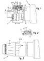
- the figures show a drilling tool 2 only indicated, in particular a hammer drill, with a tool chuck 4, which is tool-less (quick-change chuck) to a drive spindle 6 of the drilling tool 2 releasably fastened.
- the tool chuck comprises a sleeve-shaped radially inner section 8, which can be pushed onto the drive spindle 6.
- the section 8 is in the axial direction in a front receiving portion 10 for the tool, not shown.
- openings 12 are provided which allow a partial passage of spherical detent bodies 14 radially inward, but keep this detent body 14 captive in the radial direction.
- a likewise sleeve-shaped actuating means 16 is provided, which is arranged longitudinally displaceable in the direction of a tool longitudinal axis 18, by virtue of the fact that it has a coaxial with Tool longitudinal axis 18 extending threaded portion 20 is in rotary connection with the sleeve-shaped portion 8.
- a spring means 22 in the form of a leaf spring 24 is provided.
- the spring means 22 can be tensioned by an axial abutment surface 26 of the actuating means 16 in the case of axial displacement of the actuating means 16.
- the spring presses with its abutment surface 26 axially opposite end against a displacement body 28, which acts with an oblique positive displacement surface 30 on the detent body 14 and this seeks to displace radially inward.
- the axial displacement of the actuating means 16 is, as already mentioned, achieved by rotating the actuating means 16 about the tool longitudinal axis 18 through the threaded connection.
- the spring means 22 When the actuating means 16 is moved in the direction of a neck 32 of the drilling tool device 2, the spring means 22 is tensioned and thus increases the pressure on the displacement body 28, which in turn forces the locking body 14 against a groove-shaped recess 34 of the drive spindle 6 with increased pressure.
- the aforementioned components form a locking and release mechanism 36.
- these components also form a coupling device 37 with a torque adjusting device 38, wherein the sleeve-shaped actuating means 16 forms an actuating member 40 of the torque adjusting device 38.
- a user grips a front portion 46 and, in contrast, turns the sleeve-shaped actuating means 16 in the release direction until the locking bodies 14 can come free from the groove 34 on the outside of the drive spindle 6 in the radial direction. Then the tool chuck 4 can be removed in the tool longitudinal direction 18.
- the assembly process takes place in the reverse direction, wherein after establishing an axial positive connection between the drive spindle 6 and tool chuck 4 (first phase of actuation) the sleeve-shaped actuating means 16 is further rotated in positions 44 (second phase of actuation), which then goes hand in hand with a torque adjustment of the above described way.
Landscapes
- Engineering & Computer Science (AREA)
- Mechanical Engineering (AREA)
- Percussive Tools And Related Accessories (AREA)
- Drilling Tools (AREA)
- Cutting Tools, Boring Holders, And Turrets (AREA)
- Drilling And Boring (AREA)
- Earth Drilling (AREA)
Abstract
Description
- Die Erfindung betrifft ein Bohrwerkzeuggerät, insbesondere Bohrhammer, mit einem werkzeuglos an einer Antriebsspindel montierbaren und abnehmbaren Werkzeugfutter (Schnellwechselfutter) mit einem manuell bedienbaren Verriegelungs- und Freigabemechanismus für das Werkzeugfutter, und mit einer in das Werkzeugfutter integrierten Kupplungseinrichtung, zur Herbeiführung einer Drehkopplung zwischen der Antriebsspindel und dem Werkzeugfutter.
- Ein Bohrwerkzeuggerät der vorstehend genannten Art ist beispielsweise durch den Bohrhammer der Anmelderin des Handelsnamens UHE bekanntgeworden und im Hauptkatalog 2005/2006 vorbeschrieben.
- Überlastkupplungen bei Elektrohandwerkzeuggeräten sind beispielsweise durch
DE 101 31 220 Cl bekanntgeworden. - Der vorliegenden Erfindung liegt die Aufgabe zugrunde, Bohrwerkzeuggeräte, insbesondere Bohrhammer, im Hinblick auf eine weitergehende Funktionalität zu verbessern.
- Diese Aufgabe wird bei einem Bohrwerkzeuggerät der genannten Art erfindungsgemäß dadurch gelöst, dass die Kupplungseinrichtung als Überlastkupplung ausgebildet ist und das Drehmoment, bei dem die Kupplungseinrichtung entkoppelt, über eine Drehmomenteinstelleinrichtung vorgebbar ist.
- Gerade bei Bohrhämmern erweist es sich als vorteilhaft, wenn Schnellwechselfutter eingesetzt werden können, um beispielsweise ein Hammerfutter für einen Hammer- oder Bohrhammerbetrieb vorhalten und benutzen zu können oder wahlweise ein reines Bohrfutter für einen Bohrbetrieb oder in Verbindung mit Bits für einen Schraubbetrieb auswählen zu können. Die Integration einer Überlastkupplung mit einstellbarem Drehmoment in ein Schnellwechselfutter erhöht die Funktionalität des Werkzeuggeräts und erweist sich insofern als vorteilhaft.
- In Weiterbildung der Erfindung wird vorgeschlagen, dass die Drehmomenteinstelleinrichtung von Komponenten des Verriegelungs- und Freigabemechanismus für das Werkzeugfutter gebildet ist. Auf diese Weise kann die Anzahl der Komponenten, die einerseits für die Verwirklichung eines Verriegelungs- und Freigabemechanismus und andererseits für die Ausbildung einer drehmomenteinstellbaren Kupplungseinrichtung verwendet werden müssen, reduziert werden.
- Es erweist sich als vorteilhaft, wenn der Verriegelungs- und Freigabemechanismus ein manuelles Betätigungsmittel umfasst, das insbesondere hülsenförmig ausgebildet sein kann, welches zugleich das Stellorgan für die Drehmomenteinstelleinrichtung bildet.
- Das manuelle Betätigungsmittel ist vorzugsweise in Richtung einer Werkzeuglängsachse verstellbar. Hierfür könnte ausschließlich eine Längsverschiebbarkeit für das Betätigungsmittel vorgesehen sein; indessen wird vorgeschlagen, dass das manuelle Betätigungsmittel um die Werkzeuglängsachse drehbar und dabei in Richtung der Werkzeuglängsachse verlagerbar ist.
- In Weiterbildung dieses Gedankens erweist es sich als vorteilhaft, wenn das Betätigungsmittel über ein Gewinde auf einem radial inneren hülsenförmigen Abschnitt des Werkzeugfutters sitzt, welches die Antriebsspindel umgreift. Durch diese Ausbildung ist das Betätigungsmittel einerseits drehbar geführt, und es ist andererseits eine entsprechend der Umdrehung gezielte axiale Verlagerbarkeit erreicht.
- Des Weiteren erweist es sich als vorteilhaft, wenn der Verriegelungs- und Freigabemechanismus radial verlagerbare Rastkörper, insbesondere Kugeln oder Rollen aufweist, welche das Werkzeugfutter axial mit der Antriebsspindel verbinden. Hierfür werden die Rastkörper in Ausnehmungen in der Antriebsspindel gedrückt, so dass auf diese Weise eine axiale Kopplung erreicht wird und das Werkzeugfutter fest auf der Antriebswelle sitzt.
- Der vorerwähnte hülsenförmige Abschnitt oder auch andere Komponenten des Verriegelungs- und Freigabemechanismus sind dabei so ausgebildet, dass die Rastkörper zwar radial verlagerbar, jedoch nach radial innen unverlierbar im Werkzeugfutter gehalten sind.
- Es erweist sich des Weiteren als vorteilhaft, wenn die Rastkörper nicht nur zur Ausbildung einer axialen Kopplung zwischen Werkzeugfutter und Antriebsspindel dienen, sondern, dass sie zugleich eine Drehkopplung zwischen Antriebsspindel und Werkzeugfutter bewirken, um beispielsweise einen Schlagbohrbetrieb oder einen Bohrhammerbetrieb oder auch einen reinen Bohrbetrieb ausführen zu können.
- Hierfür wirken die vorzugsweise vorgesehen Rastkörper insbesondere an der Antriebsspindel vorgesehenen Drehmitnahmemitteln zusammen. Hierbei kann es sich um Vertiefungen oder Erhöhungen handeln, die eine Drehmitnahme in Umfangsrichtung bewirken.
- Es erweist sich des Weiteren als vorteilhaft, dass die Kraft, mit der die Rastkörper gegen die Antriebsspindel bzw. gegen die Drehmitnahmemittel gedrückt werden, durch das vorausgehend erwähnte Betätigungsmittel des Verriegelungs- und Freigabemechanismus für das Werkzeugfutter einstellbar ist.
- In Weiterbildung der Erfindung wird vorgeschlagen, das Bohrwerkzeuggerät so auszubilden, dass beim Montieren des Werkzeugfutters an der Antriebsspindel in einer ersten Phase der Betätigung eine axiale Kopplung zwischen Werkzeugfutter und Antriebsspindel und in einer daran anschließenden weitergehenden zweiten Phase der Betätigung eine Veränderung des Drehmoments der Überlastkupplung bewirkt wird.
- Hierfür erweist es sich als vorteilhaft, wenn der Verriegelungs- und Freigabemechanismus einen Verdrängerkörper aufweist, der die Rastkörper gegen die Antriebsspindel drückt. Zum Lösen des Werkzeugfutters wird das Betätigungsmittel dann derart verlagert, dass der Verdrängerkörper aus seiner die Rastkörper gegen die Antriebsspindel drückenden Position gebracht wird oder seinerseits durch eine Verlagerung der Verdrängerkörper infolge einer axialen Bewegung des Futterkörpers nun selbst in Lösestellung verdrängt wird.
- Vorteilhafterweise umfasst der Verriegelungs- und Freigabemechanismus ein Federmittel, das auf den Verdrängerkörper einwirkt.
- Um eine axiale Kraftbeaufschlagung in eine radiale Verdrängung zu übertragen, erweist es sich als vorteilhaft, wenn der Verdrängerkörper eine zur Werkzeuglängsachse geneigte Fläche aufweist. Er kann dann in vorteilhafter Weise in Richtung der Werkzeuglängsachse verstellbar vorgesehen werden und dabei auf den Rastkörper einwirken.
- Es erweist sich auch als vorteilhaft, dass der Spannungszustand und damit die Federkraft des Federmittels über das Betätigungsmittel einstellbar ist.
- Die Erfindung betrifft außerdem ein Werkzeugfutter nach Anspruch 21.
- Weitere Merkmale, Einzelheiten und Vorteile der Erfindung ergeben sich aus den beigefügten Patentansprüchen und aus der zeichnerischen Darstellung und nachfolgenden Beschreibung einer bevorzugten Ausführungsform des erfindungsgemäßen Bohrwerkzeuggeräts.
- In der Zeichnung zeigt:
- Figur 1
- eine schematische teilweise Ansicht eines Bohrwerkzeuggeräts im Bereich des Werkzeugfutters;
- Figur 2
- eine schematische Schnittansicht des Bohrwerkzeuggeräts nach Figur 1 und
- Figur 3
- eine schematische Seitenansicht des Bohrwerkzeuggeräts nach Figur 1 zur Verdeutlichung verschiedener Drehstellungen eines Betätigungselements, welche ein Maß für die Drehmomenteinstellung anzeigen sollen.
- Die Figuren zeigen ein nur angedeutetes Bohrwerkzeuggerät 2, insbesondere einen Bohrhammer, mit einem Werkzeugfutter 4, welches werkzeuglos (Schnellwechselfutter) an einer Antriebsspindel 6 des Bohrwerkzeuggeräts 2 lösbar befestigbar ist.
- Das Werkzeugfutter umfasst einen hülsenförmigen radial inneren Abschnitt 8, der auf die Antriebsspindel 6 aufschiebbar ist. Der Abschnitt 8 geht in axialer Richtung über in einen vorderen Aufnahmeabschnitt 10 für das nicht dargestellte Werkzeug.
- In dem hülsenförmigen Abschnitt 8 sind Öffnungen 12 vorgesehen, die einen teilweisen Durchtritt von kugelförmigen Rastkörpern 14 nach radial innen erlauben, diese Rastkörper 14 jedoch in radialer Richtung unverlierbar halten. Außerhalb des hülsenförmigen Abschnitts 8 ist ein ebenfalls hülsenförmiges Betätigungsmittel 16 vorgesehen, das in Richtung einer Werkzeuglängsachse 18 längsverschieblich angeordnet ist, und zwar dadurch, dass es über einen koaxial zur Werkzeuglängsachse 18 verlaufenden Gewindeabschnitt 20 mit dem hülsenförmigen Abschnitt 8 in Drehverbindung steht. Zwischen dem hülsenförmigen Betätigungsmittel 16 und dem inneren hülsenförmigen Abschnitt 8 ist ein Federmittel 22 in Form einer Blattfeder 24 vorgesehen. Das Federmittel 22 ist bei axialer Verlagerung des Betätigungsmittels 16 durch eine axiale Anschlagsfläche 26 des Betätigungsmittels 16 spannbar. Die Feder drückt mit ihrem der Anschlagsfläche 26 axial gegenüberliegenden Ende gegen einen Verdrängerkörper 28, der mit einer schrägen Verdrängerfläche 30 auf den Rastkörper 14 einwirkt und diesen nach radial innen zu verdrängen sucht. Die axiale Verlagerung des Betätigungsmittels 16 wird, wie bereits erwähnt, durch Drehen des Betätigungsmittels 16 um die Werkzeuglängsachse 18 durch die Gewindeverbindung erreicht. Wenn das Betätigungsmittel 16 in Richtung auf einen Hals 32 des Bohrwerkzeuggeräts 2 bewegt wird, so wird das Federmittel 22 gespannt und damit der Druck auf den Verdrängerkörper 28 erhöht, der seinerseits mit erhöhtem Druck den Rastkörper 14 gegen eine nutförmige Ausnehmung 34 der Antriebsspindel 6 zwingt. Die vorerwähnten Komponenten bilden dabei einen Verriegelungs- und Freigabemechanismus 36. Durch Eingriff des oder der Rastkörper 14 in die Nut 34 an der Außenseite der Antriebsspindel 6 wird ein axialer Formschluss zwischen Werkzeugfutter 4 und Antriebsspindel 6 erreicht. Zugleich bilden diese Komponenten aber auch eine Kupplungseinrichtung 37 mit Drehmomenteinstelleinrichtung 38, wobei das hülsenförmige Betätigungsmittel 16 ein Stellorgan 40 der Drehmomenteinstelleinrichtung 38 bildet. Je weiter das Stellorgan 40 durch Drehen um die Werkzeuglängsachse 18 in Richtung auf den Hals 32 des Bohrwerkzeuggeräts 2 verlagert ist, desto stärker ist das Drehmoment, welches von der Antriebsspindel 6 auf den jeweiligen Rastkörper 14 aufgebracht werden muss, um diesen über noch nicht erwähnte Erhebungen 42 in der Nut 34 gegen die Kraft des Federmittels 22 und unter axialer Verlagerung des Verdrängerkörpers 28 nach radial außen drücken zu können, so dass die Antriebsspindel 6 quasi unter den Rastkörpern 14 hindurchrutscht (Rutschkupplung). Dieses Hindurchrutschen führt jedoch lediglich zu einer Überwindung der Drehkopplung zwischen Werkzeugfutter 4 und Antriebsspindel 6, nicht jedoch zu einer Aufhebung der axialen Kopplung zwischen Werkzeugfutter 4 und Antriebsspindel 6.
- Aus der Darstellung der Figur 3 sind verschiedene Drehstellungen 44 ersichtlich, welche ein Maß für die Drehmomenteinstellung anzeigen sollen.
- Zum Lösen des Werkzeugfutters 4 greift ein Benutzer einen vorderen Abschnitt 46 und dreht demgegenüber das hülsenförmige Betätigungsmittel 16 in Löserichtung bis die Rastkörper 14 in radialer Richtung aus der Nut 34 an der Außenseite der Antriebsspindel 6 freikommen können. Dann kann das Werkzeugfutter 4 in Werkzeuglängsrichtung 18 abgenommen werden. Der Montagevorgang erfolgt in umgekehrter Richtung, wobei nach Herstellen eines axialen Formschlusses zwischen Antriebsspindel 6 und Werkzeugfutter 4 (erste Phase der Betätigung) das hülsenförmige Betätigungsmittel 16 weiter gedreht wird in Positionen 44 (zweite Phase der Betätigung), was dann einhergeht mit einer Drehmomenteinstellung der vorstehend beschriebenen Weise.
Claims (21)
- Bohrwerkzeuggerät (2), insbesondere Bohrhammer, mit einem werkzeuglos an einer Antriebsspindel (6) montierbaren und abnehmbaren Werkzeugfutter (4) (Schnellwechselfutter) mit einem manuell bedienbaren Verriegelungs- und Freigabemechanismus (36) für das Werkzeugfutter, und mit einer in das Werkzeugfutter integrierten Kupplungseinrichtung (37), zur Herbeiführung einer Drehkopplung zwischen der Antriebsspindel (6) und dem Werkzeugfutter (4), dadurch gekennzeichnet, dass die Kupplungseinrichtung (37) als Überlastkupplung ausgebildet ist und das Drehmoment, bei dem die Kupplungseinrichtung (37) entkoppelt, über eine Drehmomenteinstelleinrichtung (38) vorgebbar ist.
- Bohrwerkzeuggerät nach Anspruch 1, dadurch gekennzeichnet, dass die Drehmomenteinstelleinrichtung (38) von Komponenten des Verriegelungs- und Freigabemechanismus (36) gebildet ist.
- Bohrwerkzeuggerät nach Anspruch 1 oder 2, dadurch gekennzeichnet, dass der Verriegelungs- und Freigabemechanismus (36) ein manuelles Betätigungsmittel (16) umfasst, welches zugleich das Stellorgan (40) für die Drehmomenteinstelleinrichtung (38) bildet.
- Bohrwerkzeuggerät nach Anspruch 3, dadurch gekennzeichnet, dass das manuelle Betätigungsmittel (16) hülsenförmig ist.
- Bohrwerkzeuggerät nach Anspruch 3 oder 4, dadurch gekennzeichnet, dass das manuelle Betätigungsmittel (16) in Richtung einer Werkzeuglängsachse (18) verstellbar ist.
- Bohrwerkzeuggerät nach Anspruch 5, dadurch gekennzeichnet, dass das manuelle Betätigungsmittel (16) um die Werkzeuglängsachse (18) drehbar und dabei in Richtung der Werkzeuglängsachse (18) verstellbar ist.
- Bohrwerkzeuggerät nach Anspruch 6, dadurch gekennzeichnet, dass das Betätigungsmittel (16) über ein Gewinde (20) auf einem radial inneren hülsenförmigen Abschnitt (8) des Werkzeugfutters (4) sitzt, welches die Antriebsspindel (6) umgreift.
- Bohrwerkzeuggerät nach einem oder mehreren der vorstehenden Ansprüche, dadurch gekennzeichnet, dass der Verriegelungs- und Freigabemechanismus (36) radial verlagerbare Rastkörper (14), insbesondere Kugeln oder Rollen, aufweist, welche das Werkzeugfutter (4) axial mit der Antriebsspindel (6) verbinden.
- Bohrwerkzeuggerät nach einem oder mehreren der vorstehenden Ansprüche, dadurch gekennzeichnet, dass ein hülsenförmiger Abschnitt (8) die Rastkörper (14) zwar radial verlagerbar, jedoch nach radial innen unverlierbar im Werkzeugfutter (4) hält.
- Bohrwerkzeuggerät nach Anspruch 8 oder 9, dadurch gekennzeichnet, dass die Rastkörper (14), welche das Werkzeugfutter (4) axial mit der Antriebsspindel (6) verbinden, zugleich eine Drehkopplung zwischen Antriebsspindel (6) und Werkzeugfutter (4) bewirken.
- Bohrwerkzeuggerät nach einem oder mehreren der vorstehenden Ansprüche, dadurch gekennzeichnet, dass an der Antriebsspindel (6) Drehmitnahmemittel (42) vorgesehen sind.
- Bohrwerkzeuggerät nach einem oder mehreren der vorstehenden Ansprüche, dadurch gekennzeichnet, dass die Kraft, mit der die Rastkörper (14) gegen die Antriebsspindel (6) gedrückt werden, durch das Betätigungsmittel (16) einstellbar ist.
- Bohrwerkzeuggerät nach einem oder mehreren der vorstehenden Ansprüche, dadurch gekennzeichnet, dass beim Montieren des Werkzeugfutters (4) an der Antriebsspindel (6) in einer ersten Phase der Betätigung eine axiale Kopplung zwischen Werkzeugfutter (4) und Antriebsspindel (6) und in einer daran anschließenden weitergehenden zweiten Phase der Betätigung eine Veränderung des Drehmoments der Überlastkupplung bewirkt wird.
- Bohrwerkzeuggerät nach einem oder mehreren der vorstehenden Ansprüche, dadurch gekennzeichnet, dass der Verriegelungs- und Freigabemechanismus (36) einen Verdrängerkörper (28) aufweist, der die Rastkörper (14) gegen die Antriebspindel (6) drückt.
- Bohrwerkzeuggerät nach Anspruch 14, dadurch gekennzeichnet, dass der Verriegelungs- und Freigabemechanismus (36) ein Federmittel (22) umfasst, das auf den Verdrängerkörper (28) einwirkt.
- Bohrwerkzeuggerät nach Anspruch 14 oder 15, dadurch gekennzeichnet, dass der Verdrängerkörper (28) eine zur Werkzeuglängsachse geneigte Fläche aufweist.
- Bohrwerkzeuggerät nach Anspruch 14, 15 oder 16, dadurch gekennzeichnet, dass der Verdrängerkörper (28) ringförmig ausgebildet ist.
- Bohrwerkzeuggerät nach einem der Ansprüche 14 - 17, dadurch gekennzeichnet, dass der Verdrängerkörper (28) in Richtung der Werkzeuglängsachse (18) verstellbar ist.
- Bohrwerkzeuggerät nach einem der Ansprüche 15-18, dadurch gekennzeichnet, dass das Federmittel (22) eine Druckfeder, insbesondere eine Blattfeder (24), oder eine Drehfeder ist.
- Bohrwerkzeuggerät nach einem der Ansprüche 15-19 dadurch gekennzeichnet, dass der Spannungszustand und damit die Federkraft des Federmittels (22) über das Betätigungsmittel (16) einstellbar ist.
- Werkzeuglos an einer Antriebsspindel (6) eines Bohrwerkzeuggeräts montierbares und abnehmbares Werkzeugfutter (4) für ein Bohrwerkzeuggerät, mit einem manuell bedienbaren Verriegelungs- und Freigabemechanismus (36), und mit einer in das Werkzeugfutter integrierten Kupplungseinrichtung (), zur Herbeiführung einer Drehkopplung zwischen der Antriebsspindel (6) und dem Werkzeugfutter (4), dadurch gekennzeichnet, dass die Kupplungseinrichtung (37) als Überlastkupplung ausgebildet ist und das Drehmoment, bei dem die Kupplungseinrichtung (37) entkoppelt, über eine Drehmomenteinstelleinrichtung (38) vorgebbar ist.
Priority Applications (3)
| Application Number | Priority Date | Filing Date | Title |
|---|---|---|---|
| AT05010813T ATE391585T1 (de) | 2005-05-19 | 2005-05-19 | Bohrwerkzeuggerät |
| EP05010813A EP1724068B1 (de) | 2005-05-19 | 2005-05-19 | Bohrwerkzeuggerät |
| DE502005003653T DE502005003653D1 (de) | 2005-05-19 | 2005-05-19 | Bohrwerkzeuggerät |
Applications Claiming Priority (1)
| Application Number | Priority Date | Filing Date | Title |
|---|---|---|---|
| EP05010813A EP1724068B1 (de) | 2005-05-19 | 2005-05-19 | Bohrwerkzeuggerät |
Publications (2)
| Publication Number | Publication Date |
|---|---|
| EP1724068A1 true EP1724068A1 (de) | 2006-11-22 |
| EP1724068B1 EP1724068B1 (de) | 2008-04-09 |
Family
ID=34936665
Family Applications (1)
| Application Number | Title | Priority Date | Filing Date |
|---|---|---|---|
| EP05010813A Expired - Lifetime EP1724068B1 (de) | 2005-05-19 | 2005-05-19 | Bohrwerkzeuggerät |
Country Status (3)
| Country | Link |
|---|---|
| EP (1) | EP1724068B1 (de) |
| AT (1) | ATE391585T1 (de) |
| DE (1) | DE502005003653D1 (de) |
Cited By (4)
| Publication number | Priority date | Publication date | Assignee | Title |
|---|---|---|---|---|
| EP1930125A1 (de) * | 2006-12-08 | 2008-06-11 | Robert Bosch Gmbh | Aufsatz für eine Handwerkzeugmaschine |
| WO2009156005A1 (de) * | 2008-06-24 | 2009-12-30 | Robert Bosch Gmbh | Verfahren zum betrieb einer werkzeugmaschine mit kupplungsvorrichtung |
| WO2009156003A1 (de) * | 2008-06-24 | 2009-12-30 | Robert Bosch Gmbh | Werkzeugmaschine mit kupplungsvorrichtung |
| CN104416543A (zh) * | 2013-08-23 | 2015-03-18 | 苏州宝时得电动工具有限公司 | 电动工具端头连接附件和电动工具 |
Families Citing this family (2)
| Publication number | Priority date | Publication date | Assignee | Title |
|---|---|---|---|---|
| CN111590503B (zh) * | 2020-06-05 | 2021-10-22 | 郑玲佳 | 一种气动冲击扳手 |
| EP4387812A4 (de) | 2021-08-18 | 2025-06-18 | Milwaukee Electric Tool Corporation | Kupplungsanordnung für ein elektrowerkzeug |
Citations (5)
| Publication number | Priority date | Publication date | Assignee | Title |
|---|---|---|---|---|
| DE3430530A1 (de) * | 1984-08-18 | 1986-02-27 | Helfer & Co KG, 3260 Rinteln | Drehmoment-begrenzungseinrichtung |
| DE19829960A1 (de) * | 1998-07-04 | 2000-01-20 | Norbert Felder | Drehmomentbegrenzungseinrichtung |
| EP1236538A2 (de) * | 2001-02-14 | 2002-09-04 | Black & Decker Inc. | Abnehmbares Bohrfutter |
| US20020140185A1 (en) * | 2001-04-02 | 2002-10-03 | Rohm Gmbh | Quick-release drill chuck |
| DE10131220C1 (de) * | 2001-06-28 | 2003-03-06 | Metabowerke Gmbh | Elektrohandwerkzeug mit einer Überlastkupplung |
-
2005
- 2005-05-19 EP EP05010813A patent/EP1724068B1/de not_active Expired - Lifetime
- 2005-05-19 AT AT05010813T patent/ATE391585T1/de not_active IP Right Cessation
- 2005-05-19 DE DE502005003653T patent/DE502005003653D1/de not_active Expired - Lifetime
Patent Citations (5)
| Publication number | Priority date | Publication date | Assignee | Title |
|---|---|---|---|---|
| DE3430530A1 (de) * | 1984-08-18 | 1986-02-27 | Helfer & Co KG, 3260 Rinteln | Drehmoment-begrenzungseinrichtung |
| DE19829960A1 (de) * | 1998-07-04 | 2000-01-20 | Norbert Felder | Drehmomentbegrenzungseinrichtung |
| EP1236538A2 (de) * | 2001-02-14 | 2002-09-04 | Black & Decker Inc. | Abnehmbares Bohrfutter |
| US20020140185A1 (en) * | 2001-04-02 | 2002-10-03 | Rohm Gmbh | Quick-release drill chuck |
| DE10131220C1 (de) * | 2001-06-28 | 2003-03-06 | Metabowerke Gmbh | Elektrohandwerkzeug mit einer Überlastkupplung |
Cited By (10)
| Publication number | Priority date | Publication date | Assignee | Title |
|---|---|---|---|---|
| EP1930125A1 (de) * | 2006-12-08 | 2008-06-11 | Robert Bosch Gmbh | Aufsatz für eine Handwerkzeugmaschine |
| US7793572B2 (en) | 2006-12-08 | 2010-09-14 | Robert Bosch Gmbh | Attachment for a power tool |
| WO2009156005A1 (de) * | 2008-06-24 | 2009-12-30 | Robert Bosch Gmbh | Verfahren zum betrieb einer werkzeugmaschine mit kupplungsvorrichtung |
| WO2009156003A1 (de) * | 2008-06-24 | 2009-12-30 | Robert Bosch Gmbh | Werkzeugmaschine mit kupplungsvorrichtung |
| CN102076466A (zh) * | 2008-06-24 | 2011-05-25 | 罗伯特·博世有限公司 | 具有离合器装置的工具机 |
| CN102076465A (zh) * | 2008-06-24 | 2011-05-25 | 罗伯特·博世有限公司 | 用于运行具有离合器装置的工具机的方法 |
| US8763722B2 (en) | 2008-06-24 | 2014-07-01 | Robert Bosch Gmbh | Power tool having clutch device |
| US8905153B2 (en) | 2008-06-24 | 2014-12-09 | Robert Bosch Gmbh | Method for operating a power tool having a clutch device |
| CN104416543A (zh) * | 2013-08-23 | 2015-03-18 | 苏州宝时得电动工具有限公司 | 电动工具端头连接附件和电动工具 |
| CN104416543B (zh) * | 2013-08-23 | 2016-08-10 | 苏州宝时得电动工具有限公司 | 电动工具端头连接附件和电动工具 |
Also Published As
| Publication number | Publication date |
|---|---|
| ATE391585T1 (de) | 2008-04-15 |
| DE502005003653D1 (de) | 2008-05-21 |
| EP1724068B1 (de) | 2008-04-09 |
Similar Documents
| Publication | Publication Date | Title |
|---|---|---|
| EP1504836B1 (de) | Schnellspannbohrfutter | |
| EP1464426B1 (de) | Schnellspannfutter | |
| EP2163358A1 (de) | Zusatzhandgriff für eine Handwerkzeugmaschine | |
| EP3870402B1 (de) | Bedienschlüssel für stehende und angetriebene werkzeughalter | |
| EP1109642A1 (de) | Spannfutter, insbesondere dehnspannfutter | |
| DE102014112908B3 (de) | Spannfutter | |
| WO2009015932A1 (de) | Handwerkzeugmaschine mit einem werkzeughalter | |
| DE10130520B4 (de) | Handwerkzeugmaschine mit einer Sicherheitskupplung | |
| DE60001337T2 (de) | Bohrfutter | |
| EP3279492A1 (de) | Spanneinrichtung für werkzeuge | |
| EP1724068B1 (de) | Bohrwerkzeuggerät | |
| EP1981671B1 (de) | Bohrfutter | |
| EP1946894B1 (de) | Schnellwechsel-Werkzeugfutter für Bohrhämmer oder Schlagbohrmaschinen | |
| EP0175065B1 (de) | Nachspannendes Bohrfutter | |
| DE102004012434A1 (de) | Schnellspannfutter | |
| EP1618977B1 (de) | Werkzeugaufnahme | |
| DE4141045A1 (de) | Bohrwerkzeug mit zentrierbohrer | |
| EP0086352A2 (de) | Schraubkopf | |
| DE20312887U1 (de) | Beim Betrieb rotierendes Werkzeug mit einem Werkzeugschaft | |
| EP1792679B1 (de) | Hydraulische Spanneinrichtung | |
| EP4339417A1 (de) | Spannkopfanordnung zum spannen eines bohrgestängeelemtes | |
| DE19610213A1 (de) | Spannfutter mit Bogenstück | |
| DE10260493A1 (de) | Kraftspannfutter und Ausklinkschlüssel dafür | |
| DE102013216516B4 (de) | Handwerkzeugmaschinenwerkzeugaufnahme | |
| DE102022118797B3 (de) | Bohranschlag |
Legal Events
| Date | Code | Title | Description |
|---|---|---|---|
| PUAI | Public reference made under article 153(3) epc to a published international application that has entered the european phase |
Free format text: ORIGINAL CODE: 0009012 |
|
| AK | Designated contracting states |
Kind code of ref document: A1 Designated state(s): AT BE BG CH CY CZ DE DK EE ES FI FR GB GR HU IE IS IT LI LT LU MC NL PL PT RO SE SI SK TR |
|
| AX | Request for extension of the european patent |
Extension state: AL BA HR LV MK YU |
|
| 17P | Request for examination filed |
Effective date: 20061206 |
|
| AKX | Designation fees paid |
Designated state(s): AT BE BG CH CY CZ DE DK EE ES FI FR GB GR HU IE IS IT LI LT LU MC NL PL PT RO SE SI SK TR |
|
| GRAP | Despatch of communication of intention to grant a patent |
Free format text: ORIGINAL CODE: EPIDOSNIGR1 |
|
| GRAS | Grant fee paid |
Free format text: ORIGINAL CODE: EPIDOSNIGR3 |
|
| GRAA | (expected) grant |
Free format text: ORIGINAL CODE: 0009210 |
|
| AK | Designated contracting states |
Kind code of ref document: B1 Designated state(s): AT BE BG CH CY CZ DE DK EE ES FI FR GB GR HU IE IS IT LI LT LU MC NL PL PT RO SE SI SK TR |
|
| REG | Reference to a national code |
Ref country code: GB Ref legal event code: FG4D Free format text: NOT ENGLISH |
|
| REG | Reference to a national code |
Ref country code: CH Ref legal event code: EP Ref country code: CH Ref legal event code: NV Representative=s name: TROESCH SCHEIDEGGER WERNER AG |
|
| REG | Reference to a national code |
Ref country code: IE Ref legal event code: FG4D Free format text: LANGUAGE OF EP DOCUMENT: GERMAN |
|
| REF | Corresponds to: |
Ref document number: 502005003653 Country of ref document: DE Date of ref document: 20080521 Kind code of ref document: P |
|
| PG25 | Lapsed in a contracting state [announced via postgrant information from national office to epo] |
Ref country code: SI Free format text: LAPSE BECAUSE OF FAILURE TO SUBMIT A TRANSLATION OF THE DESCRIPTION OR TO PAY THE FEE WITHIN THE PRESCRIBED TIME-LIMIT Effective date: 20080409 |
|
| PG25 | Lapsed in a contracting state [announced via postgrant information from national office to epo] |
Ref country code: ES Free format text: LAPSE BECAUSE OF FAILURE TO SUBMIT A TRANSLATION OF THE DESCRIPTION OR TO PAY THE FEE WITHIN THE PRESCRIBED TIME-LIMIT Effective date: 20080720 Ref country code: BG Free format text: LAPSE BECAUSE OF FAILURE TO SUBMIT A TRANSLATION OF THE DESCRIPTION OR TO PAY THE FEE WITHIN THE PRESCRIBED TIME-LIMIT Effective date: 20080709 Ref country code: FI Free format text: LAPSE BECAUSE OF FAILURE TO SUBMIT A TRANSLATION OF THE DESCRIPTION OR TO PAY THE FEE WITHIN THE PRESCRIBED TIME-LIMIT Effective date: 20080409 Ref country code: PT Free format text: LAPSE BECAUSE OF FAILURE TO SUBMIT A TRANSLATION OF THE DESCRIPTION OR TO PAY THE FEE WITHIN THE PRESCRIBED TIME-LIMIT Effective date: 20080910 |
|
| PG25 | Lapsed in a contracting state [announced via postgrant information from national office to epo] |
Ref country code: PL Free format text: LAPSE BECAUSE OF FAILURE TO SUBMIT A TRANSLATION OF THE DESCRIPTION OR TO PAY THE FEE WITHIN THE PRESCRIBED TIME-LIMIT Effective date: 20080409 |
|
| BERE | Be: lapsed |
Owner name: METABOWERKE G.M.B.H. Effective date: 20080531 |
|
| REG | Reference to a national code |
Ref country code: IE Ref legal event code: FD4D |
|
| ET | Fr: translation filed | ||
| PG25 | Lapsed in a contracting state [announced via postgrant information from national office to epo] |
Ref country code: MC Free format text: LAPSE BECAUSE OF NON-PAYMENT OF DUE FEES Effective date: 20080531 Ref country code: IS Free format text: LAPSE BECAUSE OF FAILURE TO SUBMIT A TRANSLATION OF THE DESCRIPTION OR TO PAY THE FEE WITHIN THE PRESCRIBED TIME-LIMIT Effective date: 20080809 |
|
| PG25 | Lapsed in a contracting state [announced via postgrant information from national office to epo] |
Ref country code: LT Free format text: LAPSE BECAUSE OF FAILURE TO SUBMIT A TRANSLATION OF THE DESCRIPTION OR TO PAY THE FEE WITHIN THE PRESCRIBED TIME-LIMIT Effective date: 20080409 Ref country code: IE Free format text: LAPSE BECAUSE OF FAILURE TO SUBMIT A TRANSLATION OF THE DESCRIPTION OR TO PAY THE FEE WITHIN THE PRESCRIBED TIME-LIMIT Effective date: 20080409 Ref country code: CZ Free format text: LAPSE BECAUSE OF FAILURE TO SUBMIT A TRANSLATION OF THE DESCRIPTION OR TO PAY THE FEE WITHIN THE PRESCRIBED TIME-LIMIT Effective date: 20080409 Ref country code: DK Free format text: LAPSE BECAUSE OF FAILURE TO SUBMIT A TRANSLATION OF THE DESCRIPTION OR TO PAY THE FEE WITHIN THE PRESCRIBED TIME-LIMIT Effective date: 20080409 Ref country code: SE Free format text: LAPSE BECAUSE OF FAILURE TO SUBMIT A TRANSLATION OF THE DESCRIPTION OR TO PAY THE FEE WITHIN THE PRESCRIBED TIME-LIMIT Effective date: 20080709 |
|
| PLBE | No opposition filed within time limit |
Free format text: ORIGINAL CODE: 0009261 |
|
| STAA | Information on the status of an ep patent application or granted ep patent |
Free format text: STATUS: NO OPPOSITION FILED WITHIN TIME LIMIT |
|
| PG25 | Lapsed in a contracting state [announced via postgrant information from national office to epo] |
Ref country code: SK Free format text: LAPSE BECAUSE OF FAILURE TO SUBMIT A TRANSLATION OF THE DESCRIPTION OR TO PAY THE FEE WITHIN THE PRESCRIBED TIME-LIMIT Effective date: 20080409 Ref country code: RO Free format text: LAPSE BECAUSE OF FAILURE TO SUBMIT A TRANSLATION OF THE DESCRIPTION OR TO PAY THE FEE WITHIN THE PRESCRIBED TIME-LIMIT Effective date: 20080409 |
|
| 26N | No opposition filed |
Effective date: 20090112 |
|
| PG25 | Lapsed in a contracting state [announced via postgrant information from national office to epo] |
Ref country code: BE Free format text: LAPSE BECAUSE OF NON-PAYMENT OF DUE FEES Effective date: 20080531 |
|
| PG25 | Lapsed in a contracting state [announced via postgrant information from national office to epo] |
Ref country code: EE Free format text: LAPSE BECAUSE OF FAILURE TO SUBMIT A TRANSLATION OF THE DESCRIPTION OR TO PAY THE FEE WITHIN THE PRESCRIBED TIME-LIMIT Effective date: 20080409 |
|
| PGFP | Annual fee paid to national office [announced via postgrant information from national office to epo] |
Ref country code: NL Payment date: 20090520 Year of fee payment: 5 |
|
| PGFP | Annual fee paid to national office [announced via postgrant information from national office to epo] |
Ref country code: AT Payment date: 20090522 Year of fee payment: 5 Ref country code: IT Payment date: 20090526 Year of fee payment: 5 |
|
| PG25 | Lapsed in a contracting state [announced via postgrant information from national office to epo] |
Ref country code: CY Free format text: LAPSE BECAUSE OF FAILURE TO SUBMIT A TRANSLATION OF THE DESCRIPTION OR TO PAY THE FEE WITHIN THE PRESCRIBED TIME-LIMIT Effective date: 20080409 |
|
| PGFP | Annual fee paid to national office [announced via postgrant information from national office to epo] |
Ref country code: CH Payment date: 20090525 Year of fee payment: 5 |
|
| PG25 | Lapsed in a contracting state [announced via postgrant information from national office to epo] |
Ref country code: HU Free format text: LAPSE BECAUSE OF FAILURE TO SUBMIT A TRANSLATION OF THE DESCRIPTION OR TO PAY THE FEE WITHIN THE PRESCRIBED TIME-LIMIT Effective date: 20081010 Ref country code: LU Free format text: LAPSE BECAUSE OF NON-PAYMENT OF DUE FEES Effective date: 20080519 |
|
| PG25 | Lapsed in a contracting state [announced via postgrant information from national office to epo] |
Ref country code: TR Free format text: LAPSE BECAUSE OF FAILURE TO SUBMIT A TRANSLATION OF THE DESCRIPTION OR TO PAY THE FEE WITHIN THE PRESCRIBED TIME-LIMIT Effective date: 20080409 |
|
| PG25 | Lapsed in a contracting state [announced via postgrant information from national office to epo] |
Ref country code: GR Free format text: LAPSE BECAUSE OF FAILURE TO SUBMIT A TRANSLATION OF THE DESCRIPTION OR TO PAY THE FEE WITHIN THE PRESCRIBED TIME-LIMIT Effective date: 20080710 |
|
| REG | Reference to a national code |
Ref country code: NL Ref legal event code: V1 Effective date: 20101201 |
|
| REG | Reference to a national code |
Ref country code: CH Ref legal event code: PL |
|
| PG25 | Lapsed in a contracting state [announced via postgrant information from national office to epo] |
Ref country code: AT Free format text: LAPSE BECAUSE OF NON-PAYMENT OF DUE FEES Effective date: 20100519 |
|
| PG25 | Lapsed in a contracting state [announced via postgrant information from national office to epo] |
Ref country code: LI Free format text: LAPSE BECAUSE OF NON-PAYMENT OF DUE FEES Effective date: 20100531 Ref country code: CH Free format text: LAPSE BECAUSE OF NON-PAYMENT OF DUE FEES Effective date: 20100531 |
|
| PG25 | Lapsed in a contracting state [announced via postgrant information from national office to epo] |
Ref country code: IT Free format text: LAPSE BECAUSE OF NON-PAYMENT OF DUE FEES Effective date: 20100519 Ref country code: NL Free format text: LAPSE BECAUSE OF NON-PAYMENT OF DUE FEES Effective date: 20101201 |
|
| REG | Reference to a national code |
Ref country code: DE Ref legal event code: R082 Ref document number: 502005003653 Country of ref document: DE Representative=s name: LORENZ & KOLLEGEN PATENTANWAELTE PARTNERSCHAFT, DE |
|
| REG | Reference to a national code |
Ref country code: FR Ref legal event code: PLFP Year of fee payment: 12 |
|
| REG | Reference to a national code |
Ref country code: FR Ref legal event code: PLFP Year of fee payment: 13 |
|
| PGFP | Annual fee paid to national office [announced via postgrant information from national office to epo] |
Ref country code: DE Payment date: 20170522 Year of fee payment: 13 Ref country code: GB Payment date: 20170524 Year of fee payment: 13 Ref country code: FR Payment date: 20170522 Year of fee payment: 13 |
|
| REG | Reference to a national code |
Ref country code: DE Ref legal event code: R119 Ref document number: 502005003653 Country of ref document: DE |
|
| GBPC | Gb: european patent ceased through non-payment of renewal fee |
Effective date: 20180519 |
|
| PG25 | Lapsed in a contracting state [announced via postgrant information from national office to epo] |
Ref country code: GB Free format text: LAPSE BECAUSE OF NON-PAYMENT OF DUE FEES Effective date: 20180519 Ref country code: FR Free format text: LAPSE BECAUSE OF NON-PAYMENT OF DUE FEES Effective date: 20180531 Ref country code: DE Free format text: LAPSE BECAUSE OF NON-PAYMENT OF DUE FEES Effective date: 20181201 |