EP1723927B1 - Self-ligating orthodontic bracket - Google Patents
Self-ligating orthodontic bracket Download PDFInfo
- Publication number
- EP1723927B1 EP1723927B1 EP06010432A EP06010432A EP1723927B1 EP 1723927 B1 EP1723927 B1 EP 1723927B1 EP 06010432 A EP06010432 A EP 06010432A EP 06010432 A EP06010432 A EP 06010432A EP 1723927 B1 EP1723927 B1 EP 1723927B1
- Authority
- EP
- European Patent Office
- Prior art keywords
- bracket
- slide member
- ligating slide
- channel
- archwire
- Prior art date
- Legal status (The legal status is an assumption and is not a legal conclusion. Google has not performed a legal analysis and makes no representation as to the accuracy of the status listed.)
- Expired - Lifetime
Links
Images






Classifications
-
- A—HUMAN NECESSITIES
- A61—MEDICAL OR VETERINARY SCIENCE; HYGIENE
- A61C—DENTISTRY; APPARATUS OR METHODS FOR ORAL OR DENTAL HYGIENE
- A61C7/00—Orthodontics, i.e. obtaining or maintaining the desired position of teeth, e.g. by straightening, evening, regulating, separating, or by correcting malocclusions
- A61C7/12—Brackets; Arch wires; Combinations thereof; Accessories therefor
- A61C7/28—Securing arch wire to bracket
- A61C7/287—Sliding locks
Definitions
- This disclosure relates to improved self-locking or ligatureless orthodontic brackets.
- Orthodontic treatment generally comprises dental work to correct irregularities of the teeth or of the relation of the teeth to surrounding anatomy.
- the irregularities may involve malocclusions with varying degrees of severity.
- Class 1 malocclusions for example, may involve spacing irregularities such as excessive crowding or diastema (a gap between two adjacent teeth).
- Class 2 malocclusions may involve overbite conditions where the upper anterior teeth project labially over the lower anterior teeth.
- Class 3 malocclusions in contrast, may involve underbite conditions where the upper anterior teeth close within the lingual side of the lower anterior teeth.
- For these and other observed irregularities treatment typically involves installation of braces or mechanical aids for repositioning the teeth into correct orthodontic alignment.
- Braces generally include orthodontic brackets configured for attachment to the labial or lingual surfaces of the teeth or for attachment to metallic bands secured around the teeth.
- the brackets typically include archwire slots within which a flexible yet resilient archwire may be engaged.
- Each bracket is typically bonded to the tooth surface so that the bracket's archwire slot is oriented for engagement with the archwire.
- Various techniques are used for orienting the brackets.
- an edgewise appliance comprises braces whereby each bracket is oriented and bonded to the tooth so that the archwire slot is perpendicular to the long axis of the root of the tooth.
- a straight-wire appliance includes braces whereby each bracket is oriented and bonded to the tooth so that the archwire slot is parallel to the occlusal plane (the biting surfaces of the teeth).
- the archwire is typically a curved metallic wire having a rectangular or circular cross section that is bent or twisted prior to engagement with the brackets.
- the memory or restoring force exerted by the archwire upon the brackets serves to move the teeth into the desired alignment.
- the orthodontist periodically adjusts the shape of the archwire (as well as the configuration of other attachments such as elastic bands and so forth) to achieve the correct orthodontic alignment.
- brackets in current use incorporate tie wings or extensions that project upwardly and downwardly in a gingival-occlusal orientation and require the use of ligatures or ligating modules to hold the archwire within the archwire slots.
- the ligatures or ligating modules are typically donut-shaped elastomeric rings or wires that are stretched around or twisted around the tie wings.
- ligatures or ligating modules presents a number of inherent disadvantages, some of which are mentioned herein.
- the small size of the ligatures or ligating modules requires substantial time for installation of the archwire. Because the orthodontist will typically make numerous adjustments to the archwire throughout orthodontic treatment, the orthodontist will likely remove and replace the ligatures or ligating modules numerous times. Hygiene is another problem since the use of ligatures or ligating modules increases the areas where food particles may be trapped. Further, with movement due to chewing or other activities, the ligatures or ligating modules may become detached altogether, allowing the archwire to disengage from the archwire slots.
- Ligatures or ligating modules also present other limitations in terms of the forces exerted upon the brackets.
- the labial or outward force that may be applied to a tooth having a bracket bonded to its labial surface is limited to the strength of the ligature or ligating module in the labial direction.
- the force that may be applied in the lingual direction is not so constrained (because the force is applied against the bracket structure rather than the ligature or ligation module).
- the longitudinal (or mesial-distal) forces which may be applied along the direction of the archwire may be limited or defined by the friction between the ligature or ligation module and the archwire.
- a means for locking the archwire within the archwire slot would enhance the forces that may be exerted along the direction of the archwire.
- a means for slideably retaining the archwire within the archwire slot would allow greater flexibility than available from brackets requiring the use of ligatures or ligation modules.
- US patent No. 6190166 describes an orthodontic device including a wire member and a fixing member.
- the wire member consists of an archwire fixed through concatenation with a tooth and an engaging part fixed at positions corresponding to the points of fixation of the archwire.
- the fixing member fixed on the tooth is provided with a mounting groove for mounting the engaging part.
- one aspect of the present invention provides a self-ligating orthodontic bracket, comprising: a mounting base for attachment to a tooth surface; an archwire slot formed upon said base and sized for receiving an orthodontic archwire through an opening formed in a surface of the bracket opposite a tooth bonding surface of the bracket; a channel formed upon said base and transversely oriented to said archwire slot; and a ligating slide member slideably retained within said channel and closeable over said archwire slot, for retaining said orthodontic archwire therein, characterised in that said ligating slide member and said base cooperatively have at least one resilient retention mechanism aligned in coplanar relation to said ligating slide member and capable of exerting retention forces in a direction coplanar said ligating slide member and, thereby, holding said ligating slide member in a dosed position.
- said channel is formed between sides of said channel crimped inward forming a dovetail shaped channel.
- said channel includes relief grooves formed lengthwise along the base of said sides of said channel.
- said ligating slide member further comprises at least one active engagement protrusion for restrainably engaging said orthodontic archwire within said archwire slot.
- features of said bracket define a centerline transverse to said archwire slot and useful as a visual aid for positioning said bracket on said tooth surface.
- the bracket further comprises a vertical slot transverse to said archwire slot and formed between said archwire slot and a tooth bonding surface of said mounting base, said tooth bonding surface for bonding said bracket to said tooth surface.
- the bracket further comprises at least one pair of tie wings formed upon said base transverse to said archwire slot.
- said bracket comprises a biocompatible material.
- said bracket comprises an injection molded bracket body.
- said bracket comprises a cobalt chromium alloy.
- said ligating slide member includes an indent feature for slideably manipulating said ligating slide member within said channel using an orthodontic tool.
- said bracket includes an indent feature opposite said archwire slot from said ligating slide member when said ligating slide member is in an open position exposing said archwire slot, said indent feature for slideably manipulating said ligating slide member within said channel using an orthodontic tool.
- surfaces of said bracket opposite a tooth bonding surface of said mounting base comprise a convex shape for improving patient comfort, said tooth bonding surface for bonding said bracket to said tooth surface.
- said ligating slide member and said channel comprise a convex shape.
- said ligating slide member comprises at least one slide stop protrusion for holding said ligating slide member within said channel when said ligating slide member is in a fully open position exposing said archwire slot.
- said mounting base comprises a tooth bonding surface having grooves for improving adhesion to said tooth surface.
- said bracket comprises a one-piece injection molded bracket body having said ligating slide member slideably retained within said channel, said channel formed between sides of said channel crimped inward forming a dovetail shaped channel.
- said at least one resilient retention mechanism has a finger-like shape capable of deflecting in a direction transverse to and coplanar with the direction of slideable travel of said ligating slide member within said channel around a mating protrusion formed at a closing end of said channel.
- said finger-like shape makes slight contact with a secondary protrusion formed at said closing end of said channel, said secondary protrusion improving coplanar locking forces exerted on said finger-like shape.
- said base has sides defining said channel for receiving said ligating slide member with the upper portion of said sides inclined inward to form a dovetail shaped channel.
- Fig. 1 illustrates an isometric view of a self-ligating orthodontic bracket 100 according to one embodiment of the invention.
- the self-ligating orthodontic bracket 100 includes a mounting base 105 for attachment to a tooth surface, an archwire slot 110 formed upon the mounting base 105 and sized for receiving an orthodontic archwire (not shown), and a ligating slide member 115 (shown in a closed position) for retaining an orthodontic archwire within the archwire slot 110.
- the ligating slide member 115 may slide within a channel formed between sides 120 and oriented transverse to the archwire slot 110.
- the ligating slide member 115 preferably includes one or more coplanar resilient retention features (or mechanism) 125 for holding the ligating slide member 115 in a closed position thereby retaining an orthodontic archwire within the archwire slot 110.
- the one or more coplanar resilient retention features 125 may comprise resilient portions of the ligating slide member 115 suitably formed to allow coplanar deflection and subsequent locking with one or more mating protrusions 130 and 135.
- the resilient retention features 125 have been designed to deflect outward, perpendicular to the channel formed by sides 120, for lockable engagement with a larger (mating) protrusion 130 and smaller (secondary) protrusions 135. In this configuration, the resilient retention features 125 deflect and engage with the mating protrusions 130 and 135 transverse to and coplanar with the channel formed between sides 120.
- the bracket 100 may include orthodontic tool features such as the recess 140 on the top area of the bracket and the recess 145 on the ligating slide member 115. Such features may improve the ease of use of the bracket 100. For instance, an orthodontic tool such as an explorer or scaler may be used with the recess 145 to open or close the ligating slide member 115 to expose or cover the archwire slot 110. Likewise, pliers or another orthodontic tool may be used with the recesses 140 and 145 to close the ligating slide member 115. Further, the recesses 140 and 145, in combination with the protrusion 130 and other visual aspects of the bracket 100, provide a centerline for the bracket 100 useful to aid the orthodontist in the placement of the bracket 100 upon the patient's tooth.
- orthodontic tool features such as the recess 140 on the top area of the bracket and the recess 145 on the ligating slide member 115.
- an orthodontic tool such as an explorer or scaler may be used with the recess 145 to open or close
- the bracket 100 preferably includes rounded edges, chamfered archwire slot ends 150, and an overall convex shape to improve comfort for the patient wearing the orthodontic appliance.
- the ligating slide member 115, the channel formed by sides 120, and other features which may define the outer surfaces of the bracket 100 opposite the mounting base 105 preferably follow a convex shape to improve patient comfort and minimize the overall side profile or outward dimension of the bracket 100 from the bonding surface of the mounting base 105.
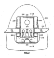
- Fig. 2 illustrates an exemplary frontal view of a self-ligating orthodontic bracket 200 placed upon a tooth 205 and engaged with an archwire 210.
- the bracket 200 is shown mounted to the labial surface of an upper anterior tooth 205 (one of the upper centrals, laterals, or cuspids).
- the bracket 200 may also be mounted to the lingual surface of a tooth 205, and the tooth 205 may comprise any tooth such as one of the upper or lower centrals, laterals, cuspids, bicuspids, molars, and so on.
- the archwire 210 is retained within the self-ligating bracket 200 and runs parallel to the occlusal surface (the cutting or incisal edge) of the tooth 205.
- Other orientations may be used with the bracket 200. However, this orientation is typical of a straight-wire (or Roth) appliance whereby crown angulation and crown inclination are engineered into the bracket 200 thereby allowing use of an archwire that is "straight" or parallel to the cutting edge of each tooth (when the teeth are positioned in correct orthodontic alignment).
- Crown angulation is generally the mesial-distal to gingival-occlusal orientation of the tooth and is affected by the mesial-distal orientation of the archwire slot (or slot tip). The crown angulation for the bracket 200 as shown in Fig.
- the archwire 210 in Fig. 2 runs along a mesial-distal line parallel to the incisal edge of tooth 205 and is oriented perpendicular to the gingival-occlusal axis (or long axis) of the clinical crown.
- Other non-perpendicular crown angulations may be engineered into the bracket 200 resulting in a bracket 200 with a rhomboid or parallelogram frontal profile instead of the rectangular frontal profile depicted in Fig. 2 .
- Crown inclination is generally the labial-lingual to gingival-occlusal orientation of the tooth and is affected by the rotational orientation of the archwire slot (or slot torque) along the mesial-distal (or archwire) axis.
- the rotational orientation of the archwire slot will be discussed in greater detail below in the context of axial or sectional views of the bracket along the mesial-distal axis.
- a straight-wire appliance typically includes individually engineered brackets with each bracket having the desired crown inclination (slot torque) and crown angulation (slot tip) for a particular tooth
- a standard edgewise appliance typically includes brackets having a rectangular profile and an orientation such that the centerline of the bracket is aligned along the gingival-occlusal axis (or long axis) of the clinical crown and perpendicular with the archwire slot.
- the brackets in a standard edgewise appliance have archwire slots that are not parallel to the incisal edges of the teeth (when the teeth are positioned in correct orthodontic alignment). Instead, the archwire is angled, bent, and twisted to define the desired position of the teeth.
- the mounting base 215 of the bracket 200 may be sized to fit the particular tooth surface 205.
- the mounting base 215 may be wider at the incisal end of the tooth 205 to match the shape of the tooth surface.
- the bracket 200 may be bonded to the surface of tooth 205, or, alternatively, to a band assembly (not shown) which is attached to the tooth 205.
- the bracket 200 is oriented so that the ligating slide member 220 slideably opens in the gingival direction and closes in the occlusal direction.
- the bracket may be oppositely oriented so that the ligating slide member 220 slideably opens in the occlusal direction and closes in the gingival direction.
- the ligating slide member 220 is shown in a closed position for retaining the archwire 210.
- the ligating slide member 220 may slide within a channel formed between sides 225 and oriented transverse to the archwire slot.
- the ligating slide member 220 preferably includes one or more coplanar resilient retention features (or mechanism) 230 for holding the ligating slide member 220 in a closed position thereby retaining the archwire 210.
- the one or more coplanar resilient retention features 230 may comprise resilient portions of the ligating slide member 220 suitably formed to allow coplanar deflection and subsequent locking with one or more mating protrusions 235 and 240.
- the resilient retention features 230 have been designed to deflect outward in the mesial-distal direction, perpendicular to the (gingival-occlusal) channel formed by sides 225, for lockable engagement with a larger (mating) protrusion 235 and smaller (secondary) protrusions 240. In this configuration, the resilient retention features 230 deflect and engage with the mating protrusions 235 and 240 transverse to and coplanar with the channel formed between sides 225.
- the resilient retention features 230 resemble coplanar fingers within the ligating slide member 220 which deflect outward in a mesial-distal direction around a mating protrusion 235 within the bracket 200.
- the resilient retention features 230 deflect outward and then return toward their former positions as they lock about the mating protrusion 235.
- a small portion of the outer ends of the resilient retention features 230 make contact with the smaller protrusions 240 which improve the (inward and coplanar) locking forces exerted on the resilient retention features 230.
- the mating protrusion 235 other symmetrical aspects of the bracket 200 such as the sides 225, and the recesses 245 and 250, individually or in combination, provide a visual centerline for the bracket 200 useful to aid the orthodontist in the placement of the bracket 200 upon the tooth 205.
- FIG. 3 provides a sectional view (referenced in Fig. 2 ) of an improved orthodontic bracket 300 with active engagement protrusions 305 for actively engaging an archwire 310, according to one embodiment of the invention.
- the bracket 300 is shown with a ligating slide member 315 in a closed position for retaining the archwire 310 within the archwire slot 320.
- the underside of the ligating slide member 315 includes one or more active engagement protrusions 305 that forcibly restrain (or actively engage) the archwire 310 when the ligating slide member 315 is closed over the archwire 310.
- Active engagement of the archwire 310 within the archwire slot 320 effectively locks the archwire 310 within the archwire slot 320, thus improving mesial-distal control.
- the forces exerted from the archwire 310 in the mesial-distal direction may be transmitted to the bracket 300 through the one or more active engagement protrusions 305.
- a bracket 300 with active engagement may be used adjacent to another bracket without active engagement for closure of a diastema.
- Active engagement of the archwire 310 (particularly a rectangular archwire, as shown) within the (rectangular) archwire slot 320 also permits improved control of crown inclination.
- twists along the archwire 310 may be transmitted to the bracket 300 through the one or more active engagement protrusions 305 as well as contacts between the lengthwise edges of the rectangular archwire 310 and the surfaces of the correspondingly rectangular archwire slot 320.
- crown inclination is generally the labial-lingual to gingival-occlusal orientation of the tooth and is affected by the rotational orientation of the archwire slot 320 (or slot torque) along the mesial-distal (or archwire) axis.
- FIG 3 shows an axial (or sectional) view of the bracket 300 along the mesial-distal axis.
- the archwire slot 320 is shown angled (or rotated) slightly such that the labial-lingual sides of the archwire slot 320 (which are normal to the ligating slide member 315) are not perpendicular (or not normal) to the tooth surface 325.
- This is a typical rotational orientation for the archwire slot used in a straight-wire appliance where slot torque is engineered into the bracket.
- a standard edgewise appliance typically includes an archwire slot with sides perpendicular to the mounting surface of the tooth.
- one or more slide member stops 330 may be formed upon the underside of the ligating slide member 315 for preventing the ligating slide member 315 from sliding beyond the limits of a slide path 335 formed as a recessed area within the channel.
- bracket 300 illustrated in Fig. 3 include the convex shape of the ligating slide member 315 and other features defining the outer most surfaces of the bracket 300, a pair of tie wings 330 extending transverse to the archwire slot 320 (one extending in a gingival direction and the other extending in an occlusal direction), and a recessed area 335 (indicated by broken lines) corresponding to the recess 250 shown in Fig. 2 .
- the convex gingival-occlusal contour of the bracket 300 improves comfort for the appliance-wearing patient.
- the tie wings 330 provide additional utility and flexibility for the orthodontist in applications where the use of standard elastomeric ligatures or other attachments requiring tie wings may be desired.
- a vertical slot 350 may be incorporated into the bracket 300.
- the vertical slot 350 (indicated by broken lines) is shown oriented transverse to the archwire slot 320 in a gingival-occlusal direction and positioned between the archwire slot 320 and the mounting base of the bracket 300.
- Such a vertical slot (such as vertical slot 350) allows placement of auxiliaries in the vertical slot to facilitate tooth inclination, angulation, and rotation, if needed.
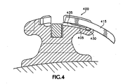
- Fig. 4 illustrates a sectional view of an improved orthodontic bracket 400 with one or more active engagement protrusions 405 and a ligating slide member 415 in a fully opened position, according to one embodiment of the invention.
- the one or more slide member stops 430 formed upon the underside of the ligating slide member 415 prevents the ligating slide member 415 from sliding beyond the end of the slide path 435.
- Fig. 5 illustrates a sectional view of an improved orthodontic bracket 500 passively engaged with an archwire 505 according to one embodiment of the invention.
- the bracket 400 shown in Fig. 4 represents the bracket 300 with the ligating slide member shown in a fully opened position
- the bracket 500 represents a similar sectional view of a different bracket.
- the bracket 500 includes a ligating slide member 510 illustrated in a closed position covering the archwire 505 such that the archwire 505 is not forcibly restrained within the archwire slot 515.
- the archwire 505 is retained within the archwire slot 515 and allowed to move within the archwire slot 515.
- the bracket 500 is said to be passively engaged with the archwire 505.
- a bracket 500 with passive engagement may be used for closure of a diastema.
- elastics may be used to urge teeth together where the brackets bonded to those teeth have freedom to move along the mesial-distal (archwire) axis.
- Figs. 6 and 7 illustrate top and bottom views, respectively, of a ligating slide member according to one embodiment of the invention.
- the ligating slide member 600 comprises a convex shaped archwire slot cover with resilient retention features 605 and 610 at one end.
- the resilient retention features 605 and 610 may comprise different shapes from those illustrated in Fig. 6 .
- the resilient retention features 605 and 610 are preferably shaped to allow deflection transverse to and coplanar with the direction of travel of the ligating slide member 600 so as to permit deflection about one or more mating protrusion features formed within the receiving (or closing) end of the channel holding the ligating slide member 600.
- the resilient retention features 605 and 610 comprise coplanar fingers formed at the locking end the ligating slide member 600.
- the resilient retention feature 605 is designed to deflect outward from the centerline of the ligating slide member 600 toward the outer edge 615.
- the resilient retention feature 610 is designed to deflect outward from the centerline of the ligating slide member 600 toward the outer edge 620. Both resilient retention features 605 and 610 spring back toward their former shapes prior to deflection thereby lockably retaining the ligating slide member 600 in a closed position.
- the underside of the ligating slide member 600 is illustrated in Fig. 7 .
- the ligating slide member may include elongated protrusions 705 and 710 for actively engaging an archwire within the archwire slot of a bracket (such as bracket 300).
- the ligating slide member preferably includes slide stop protrusions 715 and 720 for retaining the ligating slide member 600 in an open position, exposing the archwire slot of a bracket (such as bracket 300).
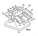
- Fig. 8 illustrates an isometric view of an improved orthodontic bracket with its ligating slide member removed, according to one embodiment of the invention.
- the bracket body 800 incorporates a convex gingival-occlusal contour extending from the tie wing 805 across the archwire slot 810 to the tie wing 815.
- the bracket body 800 incorporates a convex mesial-distal contour extending along the archwire slot 810.
- the mounting base 820 may be contoured in either or both gingival-occlusal and mesial-distal directions to improve adhesion to a tooth surface.
- the slide paths 825 and 830 are sized to receive the slide member stops 715 and 720 as well as (particularly where an active engagement ligating slide member is used) the elongated protrusions 705 and 710.
- the slide paths 825 and 830 preferably extend to the other side of the archwire slot 810 to accommodate the elongated protrusions 705 and 710 when the ligating slide member is in a closed position.
- the larger mating protrusion 835 and smaller locking protrusions 840 may be as described previously and illustrated in Figs. 1 and 2 .
- relief grooves 845, 850, 855, and 860 may be formed into the bracket base 800 to facilitate a coining operation to capture and retain a ligating slide member within a dovetail channel formed by crimping the channel sides 865, 870, 875, and 880 inward.
- the relief grooves 845, 850, 855, and 860 are formed lengthwise along the edges of the channel at the base of the channel sides 865, 870, 875, and 880.
- Fig. 9 illustrates an isometric view of an improved orthodontic bracket 900 engaged with a rectangular archwire 905 according to one embodiment of the invention.
- the channel sides 910, 915, 920, and 925 have been crimped inward to capture a ligating slide member 930.
- the ligating slide member 930 may be lockably retained in a closed position as previously described and illustrated in Figs. 1 and 2 .
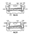
- FIGs. 10 and 11 illustrate exemplary details pertaining to a channel within which a ligating slide member may be slideably retained.
- Fig. 10 illustrates a ligating slide member 1000 placed within a channel, according to one embodiment of the invention.
- the channel comprises sides 1005, 1010, 1015, and 1020 which are then crimped inward to slideably mate with the correspondingly tapered edges 1025 and 1030 of the ligating slide member 1000.
- Relief grooves 1035 and 1040 may be formed lengthwise within the channel proximate to the lengthwise transition point where sides 1005, 1010, 1015, and 1020 extend upward from the bracket base 1045 .
- Fig. 11 illustrates a ligating slide member 1100 placed within a channel of an improved orthodontic bracket following a coining operation for retaining the ligating slide member 1100 within the channel, according to one embodiment of the invention.
- the sides 1105, 1110, 1115, and 1120 are crimped inward to slideably mate with the correspondingly tapered edges of the ligating slide member 1100.
- the result comprises a slide-type joint (sometimes referred to as a dovetail joint or dovetail shaped joint) between the sides 1105, 1110, 1115, and 1120 and the ligating slide member 1110.
- the relief grooves 1135 and 1140 may be slightly reduced in size after the coining operation to crimp the sides 1105, 1110, 1115, and 1120 inward.
- the relief groves improve the dimensional quality of the dovetail shaped channel and provide additional clearance within which the ligating slide member 1110 may slide within the channel.
- brackets may be fabricated for a particular patient by prescription.
- the brackets may be engineered to include the appropriate slot torque and slot tip for each individual tooth for the particular patient.
- specifically engineered brackets may be fabricated for the upper left central, the upper left lateral, the upper left cuspid, and so forth moving distally toward the upper left molars (using Palmer's notation for designating individual teeth).
- Each bracket typically incorporates a particular slot torque and slot tip as well as other features as may be needed.
- the bracket for the upper left cuspid may include a slot tip of, perhaps, 9° and include a ball hook for use with elastics or other features of the orthodontic appliance.
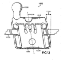
- Such a bracket may have the features as in Fig. 12 .
- Fig. 12 illustrates a top view of a parallelogram version of an improved orthodontic bracket 1200 with a ball hook 1205 , according to one embodiment of the invention.
- the bracket 1200 includes an engineered slot tip 1210 so that the bracket parallels tooth angulation for easy placement.
- the ball hook 1205 is shown formed upon the mesial gingival portion of the gingival tie wing 1215 .
- the ligating slide member 1220 is shown oriented to open in a downward direction toward the incisal edge of the tooth (as opposed to previously illustrated brackets which were oriented to open in the gingival direction, toward the gums).
- the archwire 1225 and occlusal edge 1230 of the bracket 1200 are both parallel to the incisal edge of the tooth, and the centerline 1235 of the bracket 1200 aligns with the long axis of the clinical crown.
- Fig . 13 illustrates an isometric view of an improved orthodontic bracket 1300 with a ligating slide member 1305 in an open position, according to one embodiment of the invention.
- the self-ligating orthodontic bracket 1300 includes a mounting base 1310 for attachment to a tooth surface, an archwire slot 1315 formed upon the mounting base 1310 and sized for receiving an orthodontic archwire (not shown), and the ligating slide member 1305 (shown in an open position) for retaining an orthodontic archwire within the archwire slot 1315 .
- the ligating slide member 1305 may slide within a channel formed between sides 1320 and oriented transverse to the archwire slot 1315 .
- the ligating slide member 1305 preferably includes one or more coplanar resilient retention features 1325 for holding the ligating slide member 1305 in a closed position thereby retaining an orthodontic archwire within the archwire slot 1315 .
- the one or more coplanar resilient retention features (or mechanism) 1325 may comprise resilient portions of the ligating slide member 1305 suitably formed to allow coplanar deflection and subsequent locking with one or more mating indents 1330 and 1335 .
- the resilient retention features 1325 have been designed to deflect inward, perpendicular to the channel formed by sides 1320 , for engagement with indents 1330 and 1335 . In this configuration, the resilient retention features 1325 deflect and engage with the mating indents 1330 and 1335 transverse to and coplanar with the channel formed between sides 1320.
- Slide stops to prevent the ligating slide member 1305 from pulling completely away from the rest of the bracket 1300 may be provided by suitably formed sides 1320 as shown in Fig. 13 or as described and illustrated Figs. 4 , 5 , 7 , and 8 . Also referring back to Figs. 4 , 5 , 7 , and 8 , the bracket 1300 may incorporate protrusions formed upon the ligating slide member 1305 and corresponding relief areas for active engagement with an archwire within archwire slot 1315.
- the bracket 1300 may incorporate sides 1320 that may be crimped inward as with sides 1105, 1110, 1115, and 1120 in Fig. 11 .
- the mounting base 1310 may include an uneven or rough bonding surface 1340 as shown.
- the bracket 1300 may include a ball hook attachment to one of the tie wings such as tie wing 1345, a vertical slot transverse to the archwire slot 1315 and between the archwire slot 1315 and the mounting base 1310, and a parallelogram shape as in Fig. 12 .
- the improved orthodontic bracket described herein may comprise any of a wide variety of materials suitable for use in an orthodontic appliance. Such materials have commonly included plastics, ceramics, stainless steel, titanium, or other metal alloys.
- the bracket preferably comprises a biocompatible material with corrosion resistive properties, and the bracket preferably comprises materials which may be formed into the structure shown yet maintain suitable strength characteristics for retaining commonly used orthodontic archwires or other components of an orthodontic appliance.
- Nickel may be the most common metal associated with contact dermatitis in orthodontics. Recent figures suggest that perhaps 10% of patients are sensitive to nickel. Nevertheless, nickel-containing metal alloys, such as nickel-titanium and stainless steel, are widely used in orthodontic appliances. Nickel-titanium alloys may have nickel contents above 50% and may potentially release enough nickel in the oral environment to elicit manifestations of an allergic reaction. Stainless steel has a much lower nickel content, perhaps around 8%, and, because the nickel is bound in a crystal lattice within stainless steel, the nickel may be less available to react. Consequently, stainless steel orthodontic components may be less likely to cause nickel hypersensitivity.
- nickel-containing metal alloys such as nickel-titanium and stainless steel
- the improved orthodontic bracket described herein preferably comprises a nickel-free material.
- the bracket comprises a nickel-free cobalt-chromium alloy.
- the bracket may be cast, machined, injection molded and so on. Injection molding of plastics may be used as may be ceramic injection molding (CIM) or metal injection molding (MIM) depending upon the materials chosen.
- the bracket may comprise multiple assembled components.
- the bracket may comprise the assembly of a formed bracket body and a formed ligating slide member, the ligating slide member retained within the channel of the bracket body following a coining operation whereby the channel sides are crimped inward along the sides of the ligating slide member (forming a dovetail joint).
- a ball hook may be welded to the bracket assembly, and a wire mesh may be adhered to the mounting base of the bracket to improve its bonding surface.
- the improved orthodontic bracket base is formed of nickel-free cobalt chromium using a metal injection molding process whereby the ligating slide member is similarly constructed and attached using a coining operation to crimp the sides of the bracket base (bracket body).
- the improved orthodontic bracket comprises a one-piece molded bracket body and a one-piece molded ligating slide member, the ligating slide member assembled to the bracket body using the aforementioned coining operation.
- the present invention provides an improved self-ligating orthodontic bracket.
- the improved orthodontic bracket may include a mounting base for attachment to a tooth surface, an archwire slot formed upon the base and sized for receiving an orthodontic archwire, a channel formed upon the base and transversely oriented to the archwire slot, and a ligating slide member slideably retained within the channel and closeable over the archwire slot for retaining the orthodontic archwire therein, wherein the ligating slide member includes at least one coplanar resilient retention mechanism for exerting retention forces coplanar with the ligating slide member for holding the ligating slide member in a closed position.
- the improved orthodontic bracket comprises a bracket with a ligating slide member slideably retained within a dovetail shaped channel.
Landscapes
- Health & Medical Sciences (AREA)
- Oral & Maxillofacial Surgery (AREA)
- Dentistry (AREA)
- Epidemiology (AREA)
- Life Sciences & Earth Sciences (AREA)
- Animal Behavior & Ethology (AREA)
- General Health & Medical Sciences (AREA)
- Public Health (AREA)
- Veterinary Medicine (AREA)
- Dental Tools And Instruments Or Auxiliary Dental Instruments (AREA)
Priority Applications (1)
| Application Number | Priority Date | Filing Date | Title |
|---|---|---|---|
| PL06010432T PL1723927T4 (pl) | 2005-05-19 | 2006-05-19 | Ulepszony zamek ortodontyczny |
Applications Claiming Priority (1)
| Application Number | Priority Date | Filing Date | Title |
|---|---|---|---|
| US11/134,189 US7621743B2 (en) | 2002-11-26 | 2005-05-19 | Orthodontic bracket |
Publications (2)
| Publication Number | Publication Date |
|---|---|
| EP1723927A1 EP1723927A1 (en) | 2006-11-22 |
| EP1723927B1 true EP1723927B1 (en) | 2009-08-05 |
Family
ID=36655123
Family Applications (1)
| Application Number | Title | Priority Date | Filing Date |
|---|---|---|---|
| EP06010432A Expired - Lifetime EP1723927B1 (en) | 2005-05-19 | 2006-05-19 | Self-ligating orthodontic bracket |
Country Status (9)
| Country | Link |
|---|---|
| US (1) | US7621743B2 (pl) |
| EP (1) | EP1723927B1 (pl) |
| JP (1) | JP4903502B2 (pl) |
| AT (1) | ATE438353T1 (pl) |
| AU (1) | AU2006202089B2 (pl) |
| CA (1) | CA2547433C (pl) |
| DE (1) | DE602006008211D1 (pl) |
| ES (1) | ES2331424T3 (pl) |
| PL (1) | PL1723927T4 (pl) |
Cited By (1)
| Publication number | Priority date | Publication date | Assignee | Title |
|---|---|---|---|---|
| US12622768B2 (en) | 2022-07-14 | 2026-05-12 | World Class Technology Corporation | Orthodontic appliance for correcting misalignment of teeth |
Families Citing this family (112)
| Publication number | Priority date | Publication date | Assignee | Title |
|---|---|---|---|---|
| US7419375B2 (en) * | 2002-08-19 | 2008-09-02 | Ormco Corporation | Aesthetic self-ligating orthodontic bracket |
| US7621743B2 (en) | 2002-11-26 | 2009-11-24 | Orthodontic Research And Development, S.L. | Orthodontic bracket |
| AU2003282122A1 (en) * | 2002-11-26 | 2004-06-18 | Luis Carriere Lluch | Improvements to orthodontic supports applicable to teeth |
| US7267545B2 (en) | 2005-01-11 | 2007-09-11 | Ormco Corporation | Self-ligating orthodontic bracket |
| MXPA05014182A (es) | 2005-12-21 | 2007-06-20 | Rodriguez Francisco Javier Marichi | Aparato de medicion de programacion y soldado de brackets ajustables. |
| MXPA05014181A (es) * | 2005-12-21 | 2007-06-20 | Roberto Ruiz Diaz | Sistema de brackets totalmente ajustables. |
| US7674110B2 (en) * | 2006-03-23 | 2010-03-09 | Ormco Corporation | Low profile self-ligating orthodontic brackets and methods of using such orthodontic brackets |
| US7704072B2 (en) * | 2006-04-19 | 2010-04-27 | Ormco Corporation | Orthodontic bracket |
| US20090155734A1 (en) * | 2006-04-19 | 2009-06-18 | Damon Dwight H | Orthodontic bracket |
| US7780443B2 (en) * | 2006-05-04 | 2010-08-24 | World Class Technology Corporation | Self-ligating bracket with rotary cover |
| US7585171B2 (en) * | 2006-05-04 | 2009-09-08 | World Class Technology Corporation | Orthodontic bracket with rotary ligating cover |
| DE102006021107A1 (de) * | 2006-05-05 | 2007-11-08 | Schütz, Winfried, Dr. | Regulierungsschraube für orthodontische Regulierungsapparaturen |
| WO2008031060A2 (en) | 2006-09-07 | 2008-03-13 | Rmo, Inc. | Reduced-friction buccal tube and method of use |
| US9554875B2 (en) | 2006-09-07 | 2017-01-31 | Rmo, Inc. | Method for producing a customized orthodontic appliance |
| US8979528B2 (en) | 2006-09-07 | 2015-03-17 | Rmo, Inc. | Customized orthodontic appliance method and system |
| ITFI20070069A1 (it) * | 2007-03-22 | 2008-09-23 | Leone Spa | Attacco ortodontico |
| US8469704B2 (en) * | 2007-06-28 | 2013-06-25 | Ormco Corporation | Self-ligating orthodontic bracket and devices for deploying same |
| BRPI0813295B8 (pt) * | 2007-06-28 | 2021-06-22 | Ormco Corp | bráquete ortodôntico |
| US7963767B2 (en) * | 2007-07-23 | 2011-06-21 | Ultradent Products, Inc. | Self-ligating orthodontic bracket with sliding ligation cover |
| US20090298003A1 (en) * | 2008-05-28 | 2009-12-03 | Wei Yu-Chen | Self-Ligating Orthodontic Bracket |
| US8235716B2 (en) * | 2008-06-24 | 2012-08-07 | Marc Lemchen | Method for using radio frequency identification microchips in orthodontic brackets |
| AT508036A1 (de) * | 2008-08-06 | 2010-10-15 | Pbd Patent & Business Dev Ag | Orthodontischer bauteil, insbesondere bracket |
| AU2009281952A1 (en) | 2008-08-13 | 2010-02-18 | Ormco Corporation | Aesthetic orthodontic bracket and method of making same |
| US20100112508A1 (en) * | 2008-11-03 | 2010-05-06 | Alexandre Gallo Lopes | Reversible auto-linked bracket of low profile with double lock |
| AU2009238317B2 (en) | 2008-11-14 | 2011-10-06 | Ormco Corporation | Surface treated polycrystalline ceramic orthodontic bracket and method of making same |
| CN102348427B (zh) * | 2009-01-16 | 2014-11-26 | 奥姆科公司 | 正畸托槽以及矫正错位牙齿的方法 |
| CH700504A2 (de) * | 2009-03-10 | 2010-09-15 | Dominik A Troester Dr | Nicht-ligierendes Bracket für die linguale Orthodontie. |
| US11219507B2 (en) | 2009-03-16 | 2022-01-11 | Orthoamerica Holdings, Llc | Customized orthodontic appliance and method |
| WO2010107567A1 (en) | 2009-03-16 | 2010-09-23 | Rmo, Inc. | Orthodontic bracket having an archwire channel and archwire retaining mechanism |
| US20100285420A1 (en) * | 2009-05-07 | 2010-11-11 | Ormco Corporation | Orthodontic bracket having a lingually biased closure member and associated method |
| ITVI20090191A1 (it) * | 2009-07-27 | 2011-01-28 | Hdc S R L | Dispositivo ortodontico con un sistema di fissaggio auto-legante per apparecchi ortodontici con una parte filiforme |
| US20110076633A1 (en) * | 2009-09-30 | 2011-03-31 | Orthodontic Design And Production, Inc. | Self-ligating orthodontic bracket |
| US8162660B2 (en) | 2009-11-20 | 2012-04-24 | Robert T Rudman | Rotating clip orthodontic bracket |
| EP2374429B1 (de) * | 2010-04-08 | 2014-11-19 | Wolfgang Heiser | Montageanordnung mit Hilfsmittel und kieferorthopädischem Bracket |
| US8414292B2 (en) * | 2010-08-02 | 2013-04-09 | Alexandre Gallo Lopes | Self ligating bracket system |
| CN101912312B (zh) | 2010-08-25 | 2012-08-01 | 陈启锋 | 一种舌侧托槽 |
| US9345558B2 (en) | 2010-09-03 | 2016-05-24 | Ormco Corporation | Self-ligating orthodontic bracket and method of making same |
| CN101947138B (zh) * | 2010-09-10 | 2012-08-29 | 广州瑞通生物科技有限公司 | 一种通用舌侧托槽系统 |
| US8029276B1 (en) | 2010-09-23 | 2011-10-04 | Robert Lokar | Self-ligating orthodontic bracket |
| US8998607B2 (en) | 2010-11-24 | 2015-04-07 | Ormco Corporation | Self-ligating orthodontic bracket having undercuts and related methods |
| USD648030S1 (en) * | 2011-01-25 | 2011-11-01 | Orthodontic Design And Production, Inc. | Self-ligating orthodontic bracket |
| BR112013020242A2 (pt) * | 2011-02-11 | 2016-10-18 | Orthoarm Inc | suporte ortodôntico |
| TR201101724A2 (tr) | 2011-02-22 | 2012-07-23 | M�Derr�S Ertan | Modüler ortodontik braket sistemi. |
| US9492246B2 (en) | 2011-04-19 | 2016-11-15 | 3M Innovative Properties Company | Self-ligating orthodontic appliance and related methods |
| CA2835409C (en) | 2011-05-12 | 2019-05-14 | Rmo, Inc. | Orthodontic appliance with encoded information formed in the base |
| USD847349S1 (en) | 2011-09-22 | 2019-04-30 | Rmo, Inc. | Orthodontic lock with flange |
| WO2013052029A1 (en) * | 2011-10-03 | 2013-04-11 | Lokar Robert | Self-ligating orthodontic bracket |
| US8568139B2 (en) * | 2011-11-23 | 2013-10-29 | Ronald M Roncone | Orthodontic bracket |
| CN104822339B (zh) | 2012-07-23 | 2018-03-27 | 3M创新有限公司 | 自锁正畸托槽 |
| JP5624094B2 (ja) * | 2012-08-28 | 2014-11-12 | 哲也 下田 | 歯列矯正用ブラケット |
| CN102908197B (zh) * | 2012-09-24 | 2015-04-01 | 四川大学华西口腔医院 | 一种蕊式滑盖自锁托槽 |
| ES2874777T3 (es) | 2012-10-30 | 2021-11-05 | Univ Southern California | Aparato de ortodoncia con arco de alambre encajado a presión, antideslizante |
| US9364298B2 (en) * | 2012-11-08 | 2016-06-14 | Ormco Corporation | Orthodontic bracket having a biased slide member |
| US8992214B2 (en) * | 2012-11-13 | 2015-03-31 | Mem Dental Technology Co., Ltd. | Orthodontic self-ligating brackets |
| US9089386B2 (en) | 2012-11-16 | 2015-07-28 | World Class Technology Corporation | Self-ligating bracket with sliding cover |
| US9949806B2 (en) | 2013-03-15 | 2018-04-24 | Christopher C. Cosse | Orthodontic bracket assemblies with torque-adjusting drums |
| EP2783656B1 (en) | 2013-03-15 | 2017-06-28 | American Orthodontics Corporation | Self-ligating bracket |
| JP6391681B2 (ja) | 2013-06-14 | 2018-09-19 | オルムコ コーポレイション | 回転可能クロージャ部材を有する自動結紮型歯科矯正ブラケット |
| US10945815B2 (en) | 2013-08-19 | 2021-03-16 | Premier Orthodontics Designs, Lllp | Orthodontic bracket |
| US9198740B2 (en) * | 2013-08-19 | 2015-12-01 | Premier Orthodontic Designs, Lllp | Orthodontic bracket |
| BR202013028685U2 (pt) * | 2013-11-07 | 2015-10-20 | Tecnident Equipamentos Ortodônticos Ltda | disposição construtiva aplicada em bráquete autoligado |
| US20150223914A1 (en) * | 2014-02-07 | 2015-08-13 | Lancer Orthodontics, Inc. | Self-ligating orthodontic bracket |
| BR102014013775B1 (pt) | 2014-06-06 | 2021-08-31 | Alexandre Gallo Lopes | Sistema de bráquete autoligável com clipe passívo ou interativo |
| JP1518382S (pl) * | 2014-06-10 | 2015-03-02 | ||
| US10111731B2 (en) | 2014-11-18 | 2018-10-30 | American Orthodontics Corporation | Self-ligating bracket |
| US9943383B2 (en) | 2014-12-19 | 2018-04-17 | Ormco Corporation | Biased pivoting slide orthodontic bracket |
| KR101538007B1 (ko) * | 2015-04-15 | 2015-07-22 | 주식회사 바이오세텍 | 치열 교정용 브라켓 |
| CN107847294A (zh) | 2015-06-08 | 2018-03-27 | 美国正畸公司 | 自锁托架 |
| WO2017008183A1 (zh) * | 2015-07-10 | 2017-01-19 | 杭州星辰三比齿科器材有限公司 | 一种被动自锁托槽 |
| US10182885B2 (en) | 2015-10-29 | 2019-01-22 | Mem Dental Technology Co., Ltd | Self-ligating bracket |
| US10085824B2 (en) * | 2015-10-30 | 2018-10-02 | Ortho Organizers, Inc. | Self ligating orthodontic bracket |
| USD797294S1 (en) | 2015-11-12 | 2017-09-12 | American Orthodontics Corporation | Self-ligating bracket |
| US9770310B2 (en) * | 2016-02-25 | 2017-09-26 | Pbd, Patent & Business Development Ag | Orthodontic self-ligating bracket |
| CN113288475B (zh) | 2016-04-18 | 2023-12-26 | 斯威夫特健康系统有限公司 | 具有非滑动的绑扎弓丝的牙齿正畸矫正器 |
| AU2017288247B2 (en) | 2016-06-30 | 2019-11-07 | Solventum Intellectual Properties Company | Self-ligating orthodontic bracket |
| KR101693239B1 (ko) * | 2016-07-06 | 2017-01-10 | 주식회사 페네시아 | 자가 결찰식 치열 교정용 브라켓 |
| USD804037S1 (en) | 2016-08-02 | 2017-11-28 | Henry Schein, Inc. | Self-ligating orthodontic bracket |
| US10327868B2 (en) | 2016-09-16 | 2019-06-25 | Ortho Organizers, Inc. | Self ligating orthodontic bracket with coplanar spring |
| JP7278212B2 (ja) * | 2016-09-21 | 2023-05-19 | プレミア オーソドンティック デザインズ エルエルエルピー | 歯列矯正ブラケット |
| US11376102B2 (en) | 2016-11-08 | 2022-07-05 | Robert G. Larson | Orthodontic bracket |
| US10524883B2 (en) | 2016-11-08 | 2020-01-07 | Robert G. Larson | Orthodontic bracket |
| CN110177521A (zh) | 2016-12-02 | 2019-08-27 | 斯威夫特健康系统有限公司 | 用于托槽放置的间接正畸粘结系统和方法 |
| US10881489B2 (en) | 2017-01-31 | 2021-01-05 | Swift Health Systems Inc. | Hybrid orthodontic archwires |
| USD958373S1 (en) * | 2017-03-22 | 2022-07-19 | World Class Technology Corporation | Ligating member for an orthodontic bracket |
| US11612457B2 (en) | 2017-03-22 | 2023-03-28 | World Class Technology Corporation | Adjustable hook for orthodontic brackets |
| US20180271623A1 (en) * | 2017-03-22 | 2018-09-27 | World Class Technology Corporation | Self-ligating bracket having a ligating member |
| USD926993S1 (en) | 2017-11-21 | 2021-08-03 | World Class Technology Corporation | Ligating member for an orthodontic bracket |
| US11612458B1 (en) | 2017-03-31 | 2023-03-28 | Swift Health Systems Inc. | Method of tongue preconditioning in preparation for lingual orthodontic treatment |
| CN110740704B (zh) | 2017-04-21 | 2021-10-29 | 斯威夫特健康系统有限公司 | 间接粘接托盘、非滑动正畸矫正器和使用其的配准系统 |
| CN107019569A (zh) * | 2017-05-19 | 2017-08-08 | 吉利 | 自锁托槽及其开启方法 |
| US10531936B2 (en) * | 2018-01-08 | 2020-01-14 | Innovative Material And Devices, Inc. | Dental device |
| US20190216578A1 (en) * | 2018-01-16 | 2019-07-18 | Dalia El-Bokle | Dalman orthodontic bracket |
| US11723752B2 (en) | 2018-03-12 | 2023-08-15 | 3M Innovative Properties Company | Packaged orthodontic appliances |
| US20200275996A1 (en) | 2019-03-01 | 2020-09-03 | Swift Health Systems Inc. | Indirect bonding trays with bite turbo and orthodontic auxiliary integration |
| KR102879412B1 (ko) | 2019-05-02 | 2025-10-30 | 월드 클래스 테크놀로지 코퍼레이션 | 편향된 결찰 부재가 있는 치과교정 브래킷 |
| KR20220003587A (ko) * | 2019-05-02 | 2022-01-10 | 브리우스 테크놀로지스 인코퍼레이티드 | 치열 교정 기기 |
| MX2021013328A (es) | 2019-05-02 | 2022-01-24 | Brius Tech Inc | Dispositivos dentales y metodos de fabricacion asociados. |
| CN110200711B (zh) * | 2019-06-17 | 2024-04-12 | 杭州微钢新材料科技有限公司 | 被动型牙齿矫治器 |
| WO2021087158A1 (en) | 2019-10-31 | 2021-05-06 | Swift Health Systems Inc. | Indirect orthodontic bonding systems and methods |
| WO2021170629A1 (en) * | 2020-02-28 | 2021-09-02 | Hirsch Dynamics Holding Ag | Orthodontic self-ligating bracket |
| KR102118302B1 (ko) * | 2020-05-08 | 2020-06-02 | 주식회사 지앤드아이 | 자가 결찰 치열 교정 브래킷 조립체 |
| US12090025B2 (en) | 2020-06-11 | 2024-09-17 | Swift Health Systems Inc. | Orthodontic appliance with non-sliding archform |
| US11324573B2 (en) * | 2020-07-03 | 2022-05-10 | Aadvance Technologies, Llc | Orthodontic device |
| US12144700B2 (en) | 2020-11-05 | 2024-11-19 | Brius Technologies, Inc. | Dental appliances and associated systems and methods |
| EP4304519A4 (en) | 2021-03-12 | 2025-01-15 | Swift Health Systems Inc. | INDIRECT ORTHODONTIC BONDING SYSTEMS AND PROCEDURES |
| US11490995B2 (en) | 2021-03-25 | 2022-11-08 | Brius Technologies, Inc. | Orthodontic treatment and associated devices, systems, and methods |
| US11903790B2 (en) * | 2021-04-16 | 2024-02-20 | Braces On Demand, Inc. | Self-ligating orthodontic appliances |
| US12465462B2 (en) | 2021-05-30 | 2025-11-11 | Lightforce Orthodontics, Inc. | Manufacture of patient-specific orthodontic tube |
| US12193908B2 (en) | 2021-09-03 | 2025-01-14 | Swift Health Systems, Inc. | Orthodontic appliance with non-sliding archform |
| EP4395688A4 (en) | 2021-09-03 | 2025-07-02 | Swift Health Systems Inc | METHOD OF ADMINISTERING ADHESIVE FOR BONDING ORTHODONTIC BRACKET BRACKET |
| USD1043994S1 (en) | 2022-01-06 | 2024-09-24 | Swift Health Systems Inc. | Archwire |
| WO2025259824A1 (en) * | 2024-06-12 | 2025-12-18 | Pearl Digital Inc. | Method and apparatus for providing orthodontic appliance with a ligating cover |
Family Cites Families (65)
| Publication number | Priority date | Publication date | Assignee | Title |
|---|---|---|---|---|
| US2011575A (en) | 1933-01-28 | 1935-08-20 | James W Ford | Orthodontic appliance |
| US2549528A (en) * | 1949-08-12 | 1951-04-17 | Baker & Co Inc | Orthodontic device |
| US3087244A (en) * | 1961-06-28 | 1963-04-30 | Robert J Huettner | Orthodontic attachment device |
| US3464113A (en) * | 1966-08-03 | 1969-09-02 | Elliott Silverman | Orthodontic appliance |
| US3578744A (en) | 1969-09-12 | 1971-05-18 | Alexo Corp | Method and apparatus for orthodontic treatment |
| US3946488A (en) * | 1974-10-25 | 1976-03-30 | Miller Frank R | Removable orthodontic appliance |
| US4077126A (en) | 1976-07-06 | 1978-03-07 | Pletcher Erwin Carroll | Orthodontic bracket |
| JPS5378699A (en) * | 1976-12-23 | 1978-07-12 | Kinya Fujita | Dental corrector |
| US4103423A (en) | 1977-03-04 | 1978-08-01 | Kessel Stanley P | Orthodontic bracket |
| DE2919640C2 (de) | 1979-05-16 | 1982-08-19 | Bernhard Förster GmbH, 7530 Pforzheim | Spann- und Haltevorrichtung für kieferorthopädische Zwecke |
| US4371337A (en) | 1981-05-20 | 1983-02-01 | Pletcher Erwin Carroll | Orthodontic bracket |
| US4419078A (en) | 1981-05-20 | 1983-12-06 | Pletcher Erwin Carroll | Orthodontic bracket |
| US4491825A (en) | 1981-06-09 | 1985-01-01 | Analog Devices, Incorporated | High resolution digital-to-analog converter |
| US4496318A (en) * | 1982-05-17 | 1985-01-29 | Connelly Jr Harold R | Converters for orthodontic treatment |
| US4559012A (en) | 1984-12-06 | 1985-12-17 | Pletcher Erwin Carroll | Orthodontic bracket |
| JPS61103111U (pl) | 1984-12-13 | 1986-07-01 | ||
| US4634662A (en) | 1986-02-03 | 1987-01-06 | Farel Rosenberg | Orthodontic bracket having archwire seating and locking mechanism |
| US4712999A (en) | 1986-09-10 | 1987-12-15 | Farel Rosenberg | Convertible, self-ligating, archwire positioning orthodontic bracket |
| US4698017A (en) | 1986-12-10 | 1987-10-06 | Hanson Gustaf H | Orthodontic brackets |
| US5037297A (en) | 1987-09-15 | 1991-08-06 | Lerner Harry K | Orthodontic bracket and lock pin |
| JPH03176043A (ja) | 1989-12-05 | 1991-07-31 | Hajime Suyama | 歯列矯正用ブラケット |
| US5248257A (en) | 1990-12-13 | 1993-09-28 | Cannon James L | Orthodontic bracket system |
| US5123838A (en) | 1990-12-13 | 1992-06-23 | Cannon James L | Orthodontic bracket |
| US5094614A (en) | 1991-03-08 | 1992-03-10 | Wildman Alexander J | Miniature self-locking labial bracket |
| US5322435A (en) * | 1992-07-23 | 1994-06-21 | Pletcher Erwin Carroll | Orthodontic bracket |
| US5630715A (en) | 1993-01-21 | 1997-05-20 | Voudouris; John C. | Orthodontic bracket with an engagement mechanism for retaining an archwire |
| US5429500A (en) | 1993-04-08 | 1995-07-04 | Damon Family Limited Partnership | Self-locking orthodontic bracket |
| US5275557A (en) | 1993-04-08 | 1994-01-04 | Damon Dwight H | Self-locking orthodontic bracket |
| US5466151A (en) | 1993-04-08 | 1995-11-14 | Damon Family Limited Partnership | Spring-locked orthodontic bracket |
| US5439378A (en) | 1993-04-08 | 1995-08-08 | Damon Family Limited Partnership | Orthodontic bracket assembly and method of installation |
| US5474446A (en) | 1994-07-06 | 1995-12-12 | Wildman; Alexander J. | Miniature self-locking labial bracket with cam-release closure member |
| US5738513A (en) * | 1995-11-09 | 1998-04-14 | Hermann; Lawrence | Archwire locking device for orthodontic bracket |
| US5782631A (en) | 1996-12-11 | 1998-07-21 | Kesling; Christopher K. | Orthodontic appliance |
| US6071118A (en) | 1998-02-17 | 2000-06-06 | Damon Family Limited Partnership | Self-ligating orthodontic bracket |
| EP1063936B1 (en) | 1998-02-17 | 2004-05-19 | Damon Family Limited Partnership | Self-ligating orthodontic bracket |
| US6053729A (en) * | 1998-03-02 | 2000-04-25 | Ortho Corporation | Unitary substantially nickel free alloy injection molded orthodontic bracket |
| DE19812184A1 (de) * | 1998-03-19 | 1999-09-23 | Norbert Abels | Orthodontisches Befestigungselement |
| DE19856794A1 (de) * | 1998-12-09 | 2000-06-21 | Norbert Abels | Verschlußmechanismus für eine Bracketanordnung für Zahnspangen |
| US6071119A (en) | 1998-12-22 | 2000-06-06 | 3M Innovative Properties Company | Dual mode self-ligating orthodontic bracket |
| JP3059430B1 (ja) | 1999-01-28 | 2000-07-04 | 均 篠倉 | 歯科矯正装置 |
| US6357194B1 (en) * | 1999-03-11 | 2002-03-19 | Archie Valejo Jones, Jr. | Tapered dovetail joint |
| US6193508B1 (en) | 1999-03-25 | 2001-02-27 | 3M Innovative Properties Company | Self-ligating orthodontic bracket with enhanced rotation control |
| DE10011596B4 (de) * | 2000-03-10 | 2007-12-27 | Norbert Dr. Abels | Orthodontisches Bracket |
| US6247923B1 (en) | 2000-05-24 | 2001-06-19 | Nikhil Shankarlal Vashi | Self-locking orthodontic bracket |
| US6823638B2 (en) * | 2001-06-27 | 2004-11-30 | Pergo (Europe) Ab | High friction joint, and interlocking joints for forming a generally planar surface, and method of assembling the same |
| JP4411573B2 (ja) | 2001-08-24 | 2010-02-10 | トミー株式会社 | 歯列矯正ブラケット |
| US6932597B2 (en) | 2001-09-12 | 2005-08-23 | Norbert Abels | Self-ligating orthodontic brackets including a metal ligation cover hingedly connected to a bracket base |
| US6726474B2 (en) | 2002-07-19 | 2004-04-27 | William A. Spencer | Removable self-ligating module for orthodontic brackets |
| US7419375B2 (en) * | 2002-08-19 | 2008-09-02 | Ormco Corporation | Aesthetic self-ligating orthodontic bracket |
| AU2003282122A1 (en) | 2002-11-26 | 2004-06-18 | Luis Carriere Lluch | Improvements to orthodontic supports applicable to teeth |
| US7621743B2 (en) | 2002-11-26 | 2009-11-24 | Orthodontic Research And Development, S.L. | Orthodontic bracket |
| JP4233949B2 (ja) | 2002-12-09 | 2009-03-04 | トミー株式会社 | 歯列矯正ブラケットおよびグリップ開放ツール |
| WO2004060193A1 (ja) * | 2003-01-07 | 2004-07-22 | Chikami Miltec Inc. | 歯列矯正用ブラケットおよびアーチワイヤ |
| US6866505B2 (en) | 2003-05-14 | 2005-03-15 | Self-engaging orthodontic bracket | |
| US7025591B1 (en) * | 2003-10-09 | 2006-04-11 | Tp Orthodontics, Inc. | Self-ligating orthodontic appliance |
| US6964565B2 (en) | 2004-02-19 | 2005-11-15 | Norbert Abels | Two-part orthodontic bracket |
| US7234935B2 (en) | 2004-04-29 | 2007-06-26 | Norbert Abels | Orthodontic bracket system comprising multiple brackets having multiple aligned slots |
| US7063530B2 (en) | 2004-04-30 | 2006-06-20 | Norbert Abels | Self-ligating orthodontic brackets comprising a filled and fiber-reinforced polymeric material |
| US7033170B2 (en) * | 2004-05-11 | 2006-04-25 | Mark Andrew Cordato | Orthodontic bracket and clip |
| US7175428B2 (en) | 2004-07-02 | 2007-02-13 | Nicholson James A | Shape memory self-ligating orthodontic brackets |
| US7677887B2 (en) | 2004-07-02 | 2010-03-16 | Nicholson James A | Shape memory self-ligating orthodontic brackets |
| US7252505B2 (en) | 2004-07-28 | 2007-08-07 | 3M Innovative Properties Company | Self-ligating orthodontic appliance with post for connection to a latch |
| US20060024634A1 (en) | 2004-07-28 | 2006-02-02 | 3M Innovative Properties Company | Self-ligating orthodontic appliance with clip |
| DE102004056167A1 (de) | 2004-11-18 | 2006-06-01 | Bernhard Förster Gmbh | Selbstligierendes Bracket für die Orthodontie |
| US7267545B2 (en) | 2005-01-11 | 2007-09-11 | Ormco Corporation | Self-ligating orthodontic bracket |
-
2005
- 2005-05-19 US US11/134,189 patent/US7621743B2/en not_active Expired - Lifetime
-
2006
- 2006-05-17 AU AU2006202089A patent/AU2006202089B2/en not_active Expired
- 2006-05-19 AT AT06010432T patent/ATE438353T1/de not_active IP Right Cessation
- 2006-05-19 JP JP2006166665A patent/JP4903502B2/ja not_active Expired - Lifetime
- 2006-05-19 EP EP06010432A patent/EP1723927B1/en not_active Expired - Lifetime
- 2006-05-19 CA CA2547433A patent/CA2547433C/en not_active Expired - Lifetime
- 2006-05-19 PL PL06010432T patent/PL1723927T4/pl unknown
- 2006-05-19 ES ES06010432T patent/ES2331424T3/es not_active Expired - Lifetime
- 2006-05-19 DE DE602006008211T patent/DE602006008211D1/de not_active Expired - Lifetime
Cited By (1)
| Publication number | Priority date | Publication date | Assignee | Title |
|---|---|---|---|---|
| US12622768B2 (en) | 2022-07-14 | 2026-05-12 | World Class Technology Corporation | Orthodontic appliance for correcting misalignment of teeth |
Also Published As
| Publication number | Publication date |
|---|---|
| ATE438353T1 (de) | 2009-08-15 |
| JP4903502B2 (ja) | 2012-03-28 |
| PL1723927T3 (pl) | 2010-01-29 |
| AU2006202089B2 (en) | 2011-10-27 |
| PL1723927T4 (pl) | 2010-04-30 |
| CA2547433A1 (en) | 2006-11-19 |
| AU2006202089A1 (en) | 2006-12-07 |
| EP1723927A1 (en) | 2006-11-22 |
| CA2547433C (en) | 2011-09-13 |
| ES2331424T3 (es) | 2010-01-04 |
| JP2006320726A (ja) | 2006-11-30 |
| DE602006008211D1 (de) | 2009-09-17 |
| US20050239012A1 (en) | 2005-10-27 |
| US7621743B2 (en) | 2009-11-24 |
Similar Documents
| Publication | Publication Date | Title |
|---|---|---|
| CA2547433C (en) | Improved orthodontic bracket | |
| US7585171B2 (en) | Orthodontic bracket with rotary ligating cover | |
| US7780443B2 (en) | Self-ligating bracket with rotary cover | |
| US20240398513A1 (en) | Orthodontic appliance with non-sliding archform | |
| US8235714B2 (en) | Convertible buccal tube orthodontic bracket | |
| JP4406004B2 (ja) | 自己解放式器具を備えた歯列矯正ブレース | |
| CA2386801A1 (en) | Orthodontic brackets and convertible buccal tubes | |
| CN108430381B (zh) | 自锁式托架 | |
| EP3745993B1 (en) | Ceramic self-ligating bracket with high labial pull strength | |
| HK1126644B (en) | Orthodontic bracket with rotary ligating cover | |
| HK1141432B (en) | Self-ligating bracket with rotary cover |
Legal Events
| Date | Code | Title | Description |
|---|---|---|---|
| PUAI | Public reference made under article 153(3) epc to a published international application that has entered the european phase |
Free format text: ORIGINAL CODE: 0009012 |
|
| AK | Designated contracting states |
Kind code of ref document: A1 Designated state(s): AT BE BG CH CY CZ DE DK EE ES FI FR GB GR HU IE IS IT LI LT LU LV MC NL PL PT RO SE SI SK TR |
|
| AX | Request for extension of the european patent |
Extension state: AL BA HR MK YU |
|
| 17P | Request for examination filed |
Effective date: 20070117 |
|
| 17Q | First examination report despatched |
Effective date: 20070220 |
|
| 17Q | First examination report despatched |
Effective date: 20070425 |
|
| AKX | Designation fees paid |
Designated state(s): AT BE BG CH CY CZ DE DK EE ES FI FR GB GR HU IE IS IT LI LT LU LV MC NL PL PT RO SE SI SK TR |
|
| RAP1 | Party data changed (applicant data changed or rights of an application transferred) |
Owner name: ORTHODONTIC RESEARCH AND DEVELOPMENT, S.L. |
|
| GRAP | Despatch of communication of intention to grant a patent |
Free format text: ORIGINAL CODE: EPIDOSNIGR1 |
|
| GRAS | Grant fee paid |
Free format text: ORIGINAL CODE: EPIDOSNIGR3 |
|
| GRAA | (expected) grant |
Free format text: ORIGINAL CODE: 0009210 |
|
| AK | Designated contracting states |
Kind code of ref document: B1 Designated state(s): AT BE BG CH CY CZ DE DK EE ES FI FR GB GR HU IE IS IT LI LT LU LV MC NL PL PT RO SE SI SK TR |
|
| REG | Reference to a national code |
Ref country code: GB Ref legal event code: FG4D |
|
| REG | Reference to a national code |
Ref country code: CH Ref legal event code: EP |
|
| REG | Reference to a national code |
Ref country code: IE Ref legal event code: FG4D |
|
| REF | Corresponds to: |
Ref document number: 602006008211 Country of ref document: DE Date of ref document: 20090917 Kind code of ref document: P |
|
| REG | Reference to a national code |
Ref country code: ES Ref legal event code: FG2A Ref document number: 2331424 Country of ref document: ES Kind code of ref document: T3 |
|
| LTIE | Lt: invalidation of european patent or patent extension |
Effective date: 20090805 |
|
| PG25 | Lapsed in a contracting state [announced via postgrant information from national office to epo] |
Ref country code: SE Free format text: LAPSE BECAUSE OF FAILURE TO SUBMIT A TRANSLATION OF THE DESCRIPTION OR TO PAY THE FEE WITHIN THE PRESCRIBED TIME-LIMIT Effective date: 20090805 Ref country code: FI Free format text: LAPSE BECAUSE OF FAILURE TO SUBMIT A TRANSLATION OF THE DESCRIPTION OR TO PAY THE FEE WITHIN THE PRESCRIBED TIME-LIMIT Effective date: 20090805 Ref country code: AT Free format text: LAPSE BECAUSE OF FAILURE TO SUBMIT A TRANSLATION OF THE DESCRIPTION OR TO PAY THE FEE WITHIN THE PRESCRIBED TIME-LIMIT Effective date: 20090805 Ref country code: IS Free format text: LAPSE BECAUSE OF FAILURE TO SUBMIT A TRANSLATION OF THE DESCRIPTION OR TO PAY THE FEE WITHIN THE PRESCRIBED TIME-LIMIT Effective date: 20091205 Ref country code: LT Free format text: LAPSE BECAUSE OF FAILURE TO SUBMIT A TRANSLATION OF THE DESCRIPTION OR TO PAY THE FEE WITHIN THE PRESCRIBED TIME-LIMIT Effective date: 20090805 |
|
| REG | Reference to a national code |
Ref country code: PL Ref legal event code: T3 |
|
| PG25 | Lapsed in a contracting state [announced via postgrant information from national office to epo] |
Ref country code: SI Free format text: LAPSE BECAUSE OF FAILURE TO SUBMIT A TRANSLATION OF THE DESCRIPTION OR TO PAY THE FEE WITHIN THE PRESCRIBED TIME-LIMIT Effective date: 20090805 Ref country code: LV Free format text: LAPSE BECAUSE OF FAILURE TO SUBMIT A TRANSLATION OF THE DESCRIPTION OR TO PAY THE FEE WITHIN THE PRESCRIBED TIME-LIMIT Effective date: 20090805 |
|
| PG25 | Lapsed in a contracting state [announced via postgrant information from national office to epo] |
Ref country code: BG Free format text: LAPSE BECAUSE OF FAILURE TO SUBMIT A TRANSLATION OF THE DESCRIPTION OR TO PAY THE FEE WITHIN THE PRESCRIBED TIME-LIMIT Effective date: 20091105 Ref country code: PT Free format text: LAPSE BECAUSE OF FAILURE TO SUBMIT A TRANSLATION OF THE DESCRIPTION OR TO PAY THE FEE WITHIN THE PRESCRIBED TIME-LIMIT Effective date: 20091205 |
|
| PG25 | Lapsed in a contracting state [announced via postgrant information from national office to epo] |
Ref country code: DK Free format text: LAPSE BECAUSE OF FAILURE TO SUBMIT A TRANSLATION OF THE DESCRIPTION OR TO PAY THE FEE WITHIN THE PRESCRIBED TIME-LIMIT Effective date: 20090805 Ref country code: EE Free format text: LAPSE BECAUSE OF FAILURE TO SUBMIT A TRANSLATION OF THE DESCRIPTION OR TO PAY THE FEE WITHIN THE PRESCRIBED TIME-LIMIT Effective date: 20090805 Ref country code: RO Free format text: LAPSE BECAUSE OF FAILURE TO SUBMIT A TRANSLATION OF THE DESCRIPTION OR TO PAY THE FEE WITHIN THE PRESCRIBED TIME-LIMIT Effective date: 20090805 Ref country code: CZ Free format text: LAPSE BECAUSE OF FAILURE TO SUBMIT A TRANSLATION OF THE DESCRIPTION OR TO PAY THE FEE WITHIN THE PRESCRIBED TIME-LIMIT Effective date: 20090805 |
|
| REG | Reference to a national code |
Ref country code: PL Ref legal event code: T4 |
|
| PG25 | Lapsed in a contracting state [announced via postgrant information from national office to epo] |
Ref country code: SK Free format text: LAPSE BECAUSE OF FAILURE TO SUBMIT A TRANSLATION OF THE DESCRIPTION OR TO PAY THE FEE WITHIN THE PRESCRIBED TIME-LIMIT Effective date: 20090805 |
|
| PLBE | No opposition filed within time limit |
Free format text: ORIGINAL CODE: 0009261 |
|
| STAA | Information on the status of an ep patent application or granted ep patent |
Free format text: STATUS: NO OPPOSITION FILED WITHIN TIME LIMIT |
|
| PG25 | Lapsed in a contracting state [announced via postgrant information from national office to epo] |
Ref country code: BE Free format text: LAPSE BECAUSE OF FAILURE TO SUBMIT A TRANSLATION OF THE DESCRIPTION OR TO PAY THE FEE WITHIN THE PRESCRIBED TIME-LIMIT Effective date: 20090805 |
|
| 26N | No opposition filed |
Effective date: 20100507 |
|
| PG25 | Lapsed in a contracting state [announced via postgrant information from national office to epo] |
Ref country code: GR Free format text: LAPSE BECAUSE OF FAILURE TO SUBMIT A TRANSLATION OF THE DESCRIPTION OR TO PAY THE FEE WITHIN THE PRESCRIBED TIME-LIMIT Effective date: 20091106 |
|
| PG25 | Lapsed in a contracting state [announced via postgrant information from national office to epo] |
Ref country code: MC Free format text: LAPSE BECAUSE OF NON-PAYMENT OF DUE FEES Effective date: 20100531 |
|
| REG | Reference to a national code |
Ref country code: CH Ref legal event code: PL |
|
| PG25 | Lapsed in a contracting state [announced via postgrant information from national office to epo] |
Ref country code: LI Free format text: LAPSE BECAUSE OF NON-PAYMENT OF DUE FEES Effective date: 20100531 Ref country code: CH Free format text: LAPSE BECAUSE OF NON-PAYMENT OF DUE FEES Effective date: 20100531 |
|
| PG25 | Lapsed in a contracting state [announced via postgrant information from national office to epo] |
Ref country code: IE Free format text: LAPSE BECAUSE OF NON-PAYMENT OF DUE FEES Effective date: 20100519 |
|
| PG25 | Lapsed in a contracting state [announced via postgrant information from national office to epo] |
Ref country code: CY Free format text: LAPSE BECAUSE OF FAILURE TO SUBMIT A TRANSLATION OF THE DESCRIPTION OR TO PAY THE FEE WITHIN THE PRESCRIBED TIME-LIMIT Effective date: 20090805 |
|
| PG25 | Lapsed in a contracting state [announced via postgrant information from national office to epo] |
Ref country code: LU Free format text: LAPSE BECAUSE OF NON-PAYMENT OF DUE FEES Effective date: 20100519 Ref country code: HU Free format text: LAPSE BECAUSE OF FAILURE TO SUBMIT A TRANSLATION OF THE DESCRIPTION OR TO PAY THE FEE WITHIN THE PRESCRIBED TIME-LIMIT Effective date: 20100206 |
|
| REG | Reference to a national code |
Ref country code: ES Ref legal event code: GD2A Effective date: 20130108 |
|
| REG | Reference to a national code |
Ref country code: FR Ref legal event code: PLFP Year of fee payment: 11 |
|
| REG | Reference to a national code |
Ref country code: FR Ref legal event code: PLFP Year of fee payment: 12 |
|
| REG | Reference to a national code |
Ref country code: FR Ref legal event code: PLFP Year of fee payment: 13 |
|
| PGFP | Annual fee paid to national office [announced via postgrant information from national office to epo] |
Ref country code: NL Payment date: 20250526 Year of fee payment: 20 |
|
| PGFP | Annual fee paid to national office [announced via postgrant information from national office to epo] |
Ref country code: PL Payment date: 20250507 Year of fee payment: 20 Ref country code: DE Payment date: 20250529 Year of fee payment: 20 |
|
| PGFP | Annual fee paid to national office [announced via postgrant information from national office to epo] |
Ref country code: GB Payment date: 20250527 Year of fee payment: 20 Ref country code: ES Payment date: 20250602 Year of fee payment: 20 |
|
| PGFP | Annual fee paid to national office [announced via postgrant information from national office to epo] |
Ref country code: IT Payment date: 20250521 Year of fee payment: 20 |
|
| PGFP | Annual fee paid to national office [announced via postgrant information from national office to epo] |
Ref country code: FR Payment date: 20250526 Year of fee payment: 20 |
|
| PGFP | Annual fee paid to national office [announced via postgrant information from national office to epo] |
Ref country code: TR Payment date: 20250515 Year of fee payment: 20 |
|
| REG | Reference to a national code |
Ref country code: DE Ref legal event code: R071 Ref document number: 602006008211 Country of ref document: DE |
|
| REG | Reference to a national code |
Ref country code: NL Ref legal event code: MK Effective date: 20260518 |
|
| REG | Reference to a national code |
Ref country code: ES Ref legal event code: FD2A Effective date: 20260526 |
|
| REG | Reference to a national code |
Ref country code: GB Ref legal event code: PE20 Expiry date: 20260518 |
|
| PG25 | Lapsed in a contracting state [announced via postgrant information from national office to epo] |
Ref country code: ES Free format text: LAPSE BECAUSE OF EXPIRATION OF PROTECTION Effective date: 20260520 |
|
| PG25 | Lapsed in a contracting state [announced via postgrant information from national office to epo] |
Ref country code: GB Free format text: LAPSE BECAUSE OF EXPIRATION OF PROTECTION Effective date: 20260518 |