EP1722441A1 - Anordnung zum elektrisch leitenden Verbinden von Schaltfeldem einer Hochspannungsanlage - Google Patents
Anordnung zum elektrisch leitenden Verbinden von Schaltfeldem einer Hochspannungsanlage Download PDFInfo
- Publication number
- EP1722441A1 EP1722441A1 EP05291007A EP05291007A EP1722441A1 EP 1722441 A1 EP1722441 A1 EP 1722441A1 EP 05291007 A EP05291007 A EP 05291007A EP 05291007 A EP05291007 A EP 05291007A EP 1722441 A1 EP1722441 A1 EP 1722441A1
- Authority
- EP
- European Patent Office
- Prior art keywords
- busbars
- shells
- arrangement
- diameter
- contact surface
- Prior art date
- Legal status (The legal status is an assumption and is not a legal conclusion. Google has not performed a legal analysis and makes no representation as to the accuracy of the status listed.)
- Granted
Links
- 239000004020 conductor Substances 0.000 claims abstract description 24
- XAGFODPZIPBFFR-UHFFFAOYSA-N aluminium Chemical compound [Al] XAGFODPZIPBFFR-UHFFFAOYSA-N 0.000 claims abstract description 23
- 229910052782 aluminium Inorganic materials 0.000 claims abstract description 23
- 230000002093 peripheral effect Effects 0.000 claims description 3
- RYGMFSIKBFXOCR-UHFFFAOYSA-N Copper Chemical compound [Cu] RYGMFSIKBFXOCR-UHFFFAOYSA-N 0.000 description 11
- 229910052802 copper Inorganic materials 0.000 description 11
- 239000010949 copper Substances 0.000 description 11
- 239000011810 insulating material Substances 0.000 description 2
- 238000004519 manufacturing process Methods 0.000 description 2
- 229920002943 EPDM rubber Polymers 0.000 description 1
- 230000005540 biological transmission Effects 0.000 description 1
- 239000003795 chemical substances by application Substances 0.000 description 1
- HQQADJVZYDDRJT-UHFFFAOYSA-N ethene;prop-1-ene Chemical group C=C.CC=C HQQADJVZYDDRJT-UHFFFAOYSA-N 0.000 description 1
- 239000007789 gas Substances 0.000 description 1
- 238000009499 grossing Methods 0.000 description 1
- 239000011261 inert gas Substances 0.000 description 1
- 238000009413 insulation Methods 0.000 description 1
- 239000012212 insulator Substances 0.000 description 1
- 238000000034 method Methods 0.000 description 1
- 230000035515 penetration Effects 0.000 description 1
- 230000001681 protective effect Effects 0.000 description 1
- 229920002379 silicone rubber Polymers 0.000 description 1
- 239000004945 silicone rubber Substances 0.000 description 1
- 230000006641 stabilisation Effects 0.000 description 1
- 238000011105 stabilization Methods 0.000 description 1
- 229920001897 terpolymer Polymers 0.000 description 1
Images

Classifications
-
- H—ELECTRICITY
- H01—ELECTRIC ELEMENTS
- H01R—ELECTRICALLY-CONDUCTIVE CONNECTIONS; STRUCTURAL ASSOCIATIONS OF A PLURALITY OF MUTUALLY-INSULATED ELECTRICAL CONNECTING ELEMENTS; COUPLING DEVICES; CURRENT COLLECTORS
- H01R4/00—Electrically-conductive connections between two or more conductive members in direct contact, i.e. touching one another; Means for effecting or maintaining such contact; Electrically-conductive connections having two or more spaced connecting locations for conductors and using contact members penetrating insulation
- H01R4/58—Electrically-conductive connections between two or more conductive members in direct contact, i.e. touching one another; Means for effecting or maintaining such contact; Electrically-conductive connections having two or more spaced connecting locations for conductors and using contact members penetrating insulation characterised by the form or material of the contacting members
- H01R4/60—Connections between or with tubular conductors
-
- H—ELECTRICITY
- H01—ELECTRIC ELEMENTS
- H01R—ELECTRICALLY-CONDUCTIVE CONNECTIONS; STRUCTURAL ASSOCIATIONS OF A PLURALITY OF MUTUALLY-INSULATED ELECTRICAL CONNECTING ELEMENTS; COUPLING DEVICES; CURRENT COLLECTORS
- H01R11/00—Individual connecting elements providing two or more spaced connecting locations for conductive members which are, or may be, thereby interconnected, e.g. end pieces for wires or cables supported by the wire or cable and having means for facilitating electrical connection to some other wire, terminal, or conductive member, blocks of binding posts
- H01R11/03—Individual connecting elements providing two or more spaced connecting locations for conductive members which are, or may be, thereby interconnected, e.g. end pieces for wires or cables supported by the wire or cable and having means for facilitating electrical connection to some other wire, terminal, or conductive member, blocks of binding posts characterised by the relationship between the connecting locations
- H01R11/07—Individual connecting elements providing two or more spaced connecting locations for conductive members which are, or may be, thereby interconnected, e.g. end pieces for wires or cables supported by the wire or cable and having means for facilitating electrical connection to some other wire, terminal, or conductive member, blocks of binding posts characterised by the relationship between the connecting locations the connecting locations being of the same type but different sizes
-
- H—ELECTRICITY
- H01—ELECTRIC ELEMENTS
- H01R—ELECTRICALLY-CONDUCTIVE CONNECTIONS; STRUCTURAL ASSOCIATIONS OF A PLURALITY OF MUTUALLY-INSULATED ELECTRICAL CONNECTING ELEMENTS; COUPLING DEVICES; CURRENT COLLECTORS
- H01R4/00—Electrically-conductive connections between two or more conductive members in direct contact, i.e. touching one another; Means for effecting or maintaining such contact; Electrically-conductive connections having two or more spaced connecting locations for conductors and using contact members penetrating insulation
- H01R4/28—Clamped connections, spring connections
- H01R4/38—Clamped connections, spring connections utilising a clamping member acted on by screw or nut
- H01R4/44—Clamping areas on both sides of screw
-
- H—ELECTRICITY
- H02—GENERATION; CONVERSION OR DISTRIBUTION OF ELECTRIC POWER
- H02B—BOARDS, SUBSTATIONS OR SWITCHING ARRANGEMENTS FOR THE SUPPLY OR DISTRIBUTION OF ELECTRIC POWER
- H02B13/00—Arrangement of switchgear in which switches are enclosed in, or structurally associated with, a casing, e.g. cubicle
- H02B13/005—Electrical connection between switchgear cells
Definitions
- the invention relates to an arrangement for electrically conductive connection of panels of a high-voltage system, in which an electrical contact surface is led out of each switching field, wherein between each two switching fields with their contact surfaces electrically conductive busbar is arranged and in which two busbars with each other and are electrically connected to the respective contact surface of a switching field (Prospekf Siemens AG "Siemens HA 35.41, 2003 - Components").
- switches are included, which serve for switching on and for interrupting transmission links.
- the switches are operated in air or under SF 6 protective gas. They are usually arranged in each case in a housing, from which an electrically conductive contact is led out.
- Two or two such constructed switch panels are connected to each other via busbars, which are connected to the respective contacts of the panels.
- the length of such busbars can be between 0.2 m and 1.5 m. They must be able to carry currents with a current strength of up to 1500 A in modern plants, which are operated with voltages of up to 36 kV.
- copper bars of circular cross-section are used as bus bars, which are insulated from silicone rubber or from an ethylene-propylene terpolymer (EPDM). have, which is coated on both sides with electrically conductive material. The production of these copper rods is expensive.
- the invention has for its object to make the above-described arrangement so that they can be made cheaper in a simplified structure, connected to a secure electrical connection.
- the medium voltage cable can be continuously manufactured in conventional technology with all the necessary layers surrounding the aluminum conductors.
- To produce a busbar only a predetermined length needs to be cut off from the center cable. At the ends of this length, the aluminum conductor is then exposed as far as is necessary for an attachment of the half-shells of the clamping body. Two such busbars can then be electrically conductively connected by means of the clamp body without further work. In particular, no further work on the busbars themselves is required.
- a busbar with aluminum conductors to be connected to a preferably already mounted busbar with copper rod whose diameter is smaller than the diameter of the aluminum conductor can be placed to compensate for the differences in diameter on the copper rod, a metallic ring.
- the ring may have on its outer peripheral surface over its entire axial width a plurality of circumferentially circumferential grooves. He may also have an axially continuous slot. When tightening the screw of the half-shells penetrate their projections in the grooves of the ring and the ring is pressed firmly onto the copper rod.
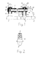
- Fig. 1 two panels of a high voltage system are shown schematically, which are electrically connected to each other by means of a busbar 1.
- the switches of the panels not shown are arranged in boilers 2, from which electrical contacts 3 are led out.
- Boilers 2 can use SF 6 as inert gas be filled, especially when switching at higher voltages.
- the contacts 3 are surrounded by insulators 4. They end at the free end face in a contact surface 5 (FIG. 2).
- the busbar 1 At the ends of the busbar 1 are made of two half-shells 6 and 7 existing clamping body, which by means of a screwed into the contact surface 5 threaded rod 8 and a threaded nut 9 for fixed contact with the busbar 1 and a subsequent thereto busbar 10 on the one hand and on the contact surface 5 of the contact 3 are brought on the other hand.
- the executed as a through connection between the busbars 1 and 10 and the contact 3 is embedded in a plug 11 made of insulating material.
- the plug 11 is closed with a cap and connected via a terminal 12 to earth or ground.
- the embedding in a plug 11 also applies if the connection point is designed as an end connection, as shown in Fig. 1 on the left.
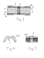
- connection point designed as a through connection is shown in FIG. 3 in an enlarged representation in comparison to FIG.
- the busbars 1 and 10 in this embodiment consist of sections of a medium voltage cable - hereinafter referred to as "cable" - with an aluminum conductor 13, which has been continuously manufactured in conventional technology.
- the aluminum conductor 13 of the cable is surrounded by a semiconducting layer 14 serving as a conductor smoothing, over which an insulation 15 is attached. This in turn is surrounded by a field control serving outer conductive layer 16.
- the layers 14, 15 and 16 are applied to the aluminum conductor 13 in one operation during the production of the cable. Together with it they form the soul of the cable.
- the busbars 1 and 10 are shown in FIG. 3 sections of the described soul of the cable, for the connection of the two busbars 1 and 10, the layers 14, 15 and 16 are removed at the ends, so that the aluminum conductors 13 are exposed.
- the existing of the two half-shells 6 and 7 clamping body is then positioned together with the threaded rod 8.
- the two Busbars 1 and 10 are then inserted into the plug 11 and approximated to approximately to rest on the threaded rod 8 to each other. In this position, they are supported with a straight course.
- the threaded nut 9 is screwed onto the threaded rod 8 and tightened so far until the half-shells 6 and 7 firmly abut the aluminum conductors 13.
- the half-shell 7 is pressed firmly against the contact surface 5.
- Each of the two half-shells 6 and 7 has on its inner surface on both sides of a bore 17 for passing the threaded rod 8 tapered projections 18.
- the tips of the projections 18 are all parallel to each other in the same direction, in the direction of the clamping body to be formed each opposite half shell. It is thereby administratgestelit that all projections 18 penetrate firmly tightened nut 9 in the Aluminiumlelter 13.
- the arrangement can also be used if a busbar with an aluminum conductor 13 according to FIG. 6 is to be connected to a bus bar consisting of a copper rod 19. Since the copper rod 19 has a smaller diameter than the aluminum conductor 13 because of the better conductivity of the copper compared to aluminum, a diameter difference compensating metallic ring 20 is pushed onto the copper rod 19 prior to assembly of the clamp body. Its inner diameter corresponds to the diameter of the copper rod 19, while its outer diameter corresponds to the diameter of the aluminum conductor 13. In the outer peripheral surface of the ring 20 circumferentially circumferential grooves 21 are mounted on its entire axial width, in which engage the projections 18 of the half-shells 6 and 7 in the mounted position. The ring 20 may also have an axially continuous slot 22, so that it can be compressed when tightening the threaded nut 9, where appropriate, to the full contact with the copper rod 19.
- connection is then completed by screwing the threaded nut 9 on the threaded rod 8 and tightening.
- tightening the threaded nut 9 penetrate the projections 18 of the two half-shells 6 and 7 in the aluminum conductor 13 and the grooves 21 of the ring 20, which - as already mentioned - optionally compressed.
- the half-shell 7 is pressed firmly against the contact surface 5.
- an adapter 25 made of insulating material.
Landscapes
- Installation Of Bus-Bars (AREA)
- Patch Boards (AREA)
- Structure Of Telephone Exchanges (AREA)
- Distribution Board (AREA)
- Cable Accessories (AREA)
- Multi-Conductor Connections (AREA)
- Coupling Device And Connection With Printed Circuit (AREA)
- Joining Of Building Structures In Genera (AREA)
Abstract
Description
- Die Erfindung bezieht sich auf eine Anordnung zum elektrisch leitenden Verbinden von Schaltfeldern einer Hochspannungsanlage, bei welcher aus jedem Schaltteld eine elektrische Kontaktfläche herausgeführt ist, bei welcher zwischen je zwei Schaltfeldern eine mit deren Kontaktflächen elektrisch leitend verbundene Sammelschiene angeordnet ist und bei welcher jeweils zwei Sammelschienen miteinander und mit der jeweiligen Kontaktfläche eines Schaltfeldes elektrisch leitend verbunden sind (Prospekf der Siemens AG "Siemens HA 35.41, 2003 - Components").
- Derartige Anordnungen werden beispielsweise in Umspannstationen von Verteilernetzen oder bei Großkunden von EVUs eingesetzt. In den zu verbindenden Schaltfeldern sind Schalter enthalten, die zum Einschalten und zum Unterbrechen von Übertragungsstrecken dienen. In Abhängigkeit von der Höhe der zu übertragenden - und damit auch zu schaltenden - Spannung, werden die Schalter in Luft oder unter SF6-Schutzgas betrieben. Sie sind in der Regel jeweils in einem Gehäuse angeordnet, aus dem ein elektrisch leitender Kontakt herausgeführt ist. Zwei bzw. jeweils zwei derart aufgebaute Schaltfelder werden über Sammelschienen miteinander verbunden, welche an die jeweiligen Kontakte der Schaltfelder angeschlossen werden. Die Länge solcher Sammelschienen kann zwischen 0.2 m und 1,5 m liegen. Sie müssen bei modernen Anlagen, die mit Spannungen von bis zu 36 kV betrieben werden, Ströme mit einer Stromstärke von bis zu 1500 A führen können. In bekannter Technik werden als Sammelschienen Kupferstangen mit kreisförmigem Querschnitt eingesetzt, die eine Isolierung aus Silikongummi oder aus einem Ethylen-Propylen-Terpolymer (EPDM) aufweisen, welche auf beiden Seiten mit elektrisch leitfähigem Material beschichtet ist. Die Herstellung dieser Kupferstangen ist aufwendig.
- Der Erfindung liegt die Aufgabe zugrunde, die eingangs geschilderte Anordnung so zu gestalten, daß sie bei vereinfachtem Aufbau kostengünstiger gestaltet werden kann, verbunden mit einer sicheren elektrischen Durchverbindung.
- Diese Aufgabe wird gemäß der Erfindung dadurch gelöst,
- daß mindestens eine der Sammelschienen aus einem Abschnitt eines mit einem Aluminiumleiter ausgerüsteten Mittelspannungskabels besteht,
- daß zum Verbinden zweier Sammelschienen jeweils ein aus zwei Halbschalen bestehender Klemmkörper dient, dessen Halbschalen in Montageposition mittels einer Schraubverbindung auf zwei einander gegenüber liegenden Seiten der zu verbindenden Sammelschienen fest an denselben anliegen, und
- daß die Halbschalen mit im wesentlichen parallel zueinander verlaufenden, spitz zulaufenden Vorsprüngen ausgerüstet sind, die jeweils in Richtung der gegenüber liegenden Halbschale weisen und in Montageposition, in welcher eine der Halbschalen fest an die zugehörige Kontaktfläche eines Schaltfeldes angepreßt ist, zumindest in den Aluminiumleiter eingedrungen sind.
- Durch die Verwendung von Abschnitten eines Mittelspannungskabels mit Aluminiumleiter kann die Anordnung wesentlich einfacher und kostengünstiger gestaltet werden. Das Mittelspannungskabel kann in herkömmlicher Technik mit allen erforderlichen, den Aluminiumleiter umgebenden Schichten kontinuierlich gefertigt werden. Zur Herstellung einer Sammelschiene braucht nur eine vorgegebene Länge von dem Mittelkabel abgeschnitten zu werden. An den Enden dieser Länge wird der Aluminiumleiter dann so weit freigelegt, wie das für eine Anbringung der Halbschalen des Klemmkörpers erforderlich ist. Zwei solche Sammelschienen können dann mittels des Klemmkörpers ohne weitere Arbeiten elektrisch leitend durchverbunden werden. Es sind insbesondere keine weiteren Arbeiten an den Sammelschienen selbst erforderlich. Durch die spitzen Vorsprünge der Halbschalen ist außerdem auf einfache Weise eine hohe Kontaktsichcrheit mit geringem Übergangswiderstand sichergestellt, da die parallel zueinander angeordneten Vorsprünge in den jeweiligen Aluminiumleiter eindringen. Die Schraubverbindung sorgt außerdem dafür, daß die Halbschalen nicht nur dicht und fest am jeweiligen Aluminlumleiter anliegen, sondern es wird gleichzeitig eine der Halbschalen fest an den Kontakt des entsprechenden Schaltfeldes gepreßt, so daß auch an dieser Stelle eine Kontaktierung mit geringem Übergangswiderstand erreicht ist.
- Wenn eine Sammelschiene mit Aluminiumleiter an eine vorzugsweise bereits montierte Sammelschiene mit Kupferstange angeschlossen werden soll, deren Durchmesser kleiner als der Durchmesser des Aluminiumleiters ist, kann zum Ausgleich der Durchmesserunterschiede auf die Kupferstange ein metallischer Ring aufgesetzt werden. Der Ring kann an seiner äußeren Umfangsfläche auf seiner ganzen axialen Breite mehrere, in Umfangsrichtung umlaufende Rillen haben. Er kann außerdem einen axial durchgehenden Schlitz aufweisen. Beim Festziehen der Verschraubung der Halbschalen dringen deren Vorsprünge in die Rillen des Rings ein und der Ring wird fest auf die Kupferstange gepreßt.
- Ausführungsbeispiele des Erfindungsgegenstandes sind in den Zeichnungen dargestellt
- Es zeigen:
- Fig. 1 in schematischer Darstellung eine Anordnung mit zwei Schaltfeldern.
- Fig. 2 eine Einzelheit aus Fig. 1 in vergrößerter Darstellung.
- Fig. 3 die Anordnung nach der Erfindung im Schnitt in ebenfalls vergrößerter Darstellung.
- Fig. 4 und 5 zwei unterschiedliche Ansichten einer in der Anordnung verwendbaren Halbschale in weiter vergrößerter Darstellung.
- Fig. 6 eine gegenüber Fig. 3 abgewandelte Ausführungsform der Anordnung ebenfalls im Schnitt.
- Fig. 7 eine Darstellung der Einzelteile der Anordnung nach Fig. 6 vor ihrem Zusammenbau.
- In Fig. 1 sind schematisch zwei Schaltfelder einer Hochspannungsanlage dargestellt, die mittels einer Sammelschiene 1 elektrisch leitend miteinander verbunden sind. Die nicht mit dargestellten Schalter der Schaltfelder sind in Kesseln 2 angeordnet, aus denen elektrische Kontakte 3 herausgeführt sind. Die Kessel 2 können mit SF6 als Schutzgas gefüllt sein, insbesondere wenn bei höheren Spannungen geschaltet werden soll. Die Kontakte 3 sind von Isolierkörpern 4 umgeben. Sie enden an deren freier Stirnseite in einer Kontaktfläche 5 (Fig. 2).
- An den Enden der Sammelschiene 1 sind aus zwei Halbschalen 6 und 7 bestehende Klemmkörper angebracht, die mittels einer in die Kontaktfläche 5 eingeschraubten Gewindestange 8 und einer Gewindemutter 9 zur festen Anlage an der Sammelschiene 1 und einer an dieselbe anschließenden Sammelschiene 10 einerseits sowie an der Kontaktfläche 5 des Kontakts 3 andererseits gebracht sind. Die als Durchverbindung ausgeführte Verbindungsstelle zwischen den Sammelschienen 1 und 10 und dem Kontakt 3 ist in einen Stecker 11 aus Isoliermaterial eingebettet. Der Stecker 11 ist mit einer Kappe verschlossen und über eine Klemme 12 an Erde bzw. Masse angeschlossen. Die Einbettung in einen Stecker 11 gilt auch dann, wenn die Verbindungsstelle als Endverbindung ausgeführt ist, so wie es in Fig. 1 links dargestellt ist.
- Eine als Durchverbindung ausgeführte Verbindungsstelle geht aus Fig. 3 in gegenüber Fig. 1 vergrößerter Darstellung hervor:
- Die Sammelschienen 1 und 10 bestehen bei dieser Ausführungsform aus Abschnitten eines Mittelspannungskabels - im folgenden kurz als "Kabel" bezeichnet - mit einem Aluminiumleiter 13, das in herkömmlicher Technik kontinuierlich gefertigt worden ist. Der Aluminiumleiter 13 des Kabels ist von einer als Leiterglättung dienenden halbleitenden Schicht 14 umgeben, über welcher eine Isolierung 15 angebracht ist. Diese wiederum ist von einer der Feldsteucrung dienenden äußeren Leitschicht 16 umgeben. Die Schichten 14, 15 und 16 werden bei der Herstellung des Kabels in einem Arbeitsgang auf den Aluminiumleiter 13 aufgebracht. Sie bilden zusammen mit demselben die Seele des Kabels.
- Die Sammelschienen 1 bzw. 10 sind entsprechend Fig. 3 Abschnitte der beschriebenen Seele des Kabels, Zur Durchverbindung der beiden Sammelschienen 1 und 10 werden die Schichten 14, 15 und 16 an deren Enden entfernt, so daß die Aluminiumleiter 13 freiliegen. Im Stecker 11 wird dann der aus den beiden Halbschalen 6 und 7 bestehende Klemmkörper zusammen mit der Gewindestange 8 positioniert. Die beiden Sammelschienen 1 und 10 werden danach in den Stecker 11 eingesteckt und bis annähernd zur Anlage an der Gewindestange 8 aneinander angenähert. In dieser Position werden sie mit geradlinigem Verlauf abgestützt. Anschließend wird die Gewindemutter 9 auf die Gewindestange 8 aufgeschraubt und so weit fest angezogen, bis die Halbschalen 6 und 7 fest an den Aluminiumleitern 13 anliegen. Dabei wird gleichzeitig die Halbschale 7 fest an die Kontaktfläche 5 gepreßt.
- Jede der beiden Halbschalen 6 und 7 hat an ihrer inneren Oberfläche beiderseits einer Bohrung 17 zum Durchführen der Gewindestange 8 spitz zulaufende Vorsprünge 18. Die Spitzen der Vorsprünge 18 weisen alle quasi parallel zueinander in die gleiche Richtung, und zwar in Richtung der im zu bildenden Klemmkörper jeweils gegenüber liegenden Halbschale. Es ist dadurch sichergestelit, daß alle Vorsprünge 18 bei fest angezogener Gewindemutter 9 in den Aluminiumlelter 13 eindringen.
- Die Anordnung ist auch dann einsetzbar, wenn eine Sammelschiene mit einem Aluminiumleiter 13 gemäß Fig. 6 mit einer aus einer Kupferstange 19 bestehenden Sammelschiene verbunden werden soll. Da die Kupferstange 19 wegen der besseren Leitfähigkeit des Kupfers gegenüber Aluminium einen kleineren Durchmesser als der Aluminiumleiter 13 hat, wird vor der Montage des Klemmkörpers ein den Durchmesserunterschied ausgleichender metallischer Ring 20 auf die Kupferstange 19 aufgeschoben. Dessen Innendurchmesser entspricht dem Durchmesser der Kupferstange 19, während sein Außendurchmesser dem Durchmesser des Aluminiumleiters 13 entspricht. In der äußeren Umfangsfläche des Rings 20 sind auf seiner ganzen axialen Breite in Umfangsrichtung umlaufende Rillen 21 angebracht, in welche die Vorsprünge 18 der Halbschalen 6 und 7 in montierter Position eingreifen. Der Ring 20 kann außerdem einen axial durchgehenden Schlitz 22 aufweisen, damit er beim Festziehen der Gewindemutter 9 gegebenenfalls bis zur satten Anlage an der Kupferstange 19 zusammengedrückt werden kann.
- Die für den Zusammenbau der Anordnung nach Fig. 6 benötigten Teile gehen als Einzelteile aus Fig. 7 hervor. Dabei sind von den beiden Sammelschienen nur Endstücke 23 und 24 dargestellt. Beim Herstellen der Verbindung werden zunächst die beiden Halbschalen 6 und 7 des Klemmkörpers zusammen mit dem Ring 20 in den oben offenen Stecker 11 eingeschoben, bis die Halbschale 7 an einer Kontaktfläche 5 anliegt. Die Halbschalen 6 und 7 werden dabei im Stecker 11 eng geführt. Danach wird die Gewindestange 8 in die Kontaktfläche 5 eingeschraubt. Anschließend werden die beiden Sammelschienen 1 und 10 in den Stecker 1 eingesteckt und in axialer Richtung weitergeschoben, bis sie in die Halbschalen 6 und 7 bzw. den Ring 20 eingreifen. In der Endposition berühren ihre Stirnflächen die Gewindestande 8 annähernd. Die Verbindung wird dann durch Aufschrauben der Gewindemutter 9 auf die Gewindestange 8 und deren Festziehen fertiggestellt. Beim Festziehen der Gewindemutter 9 dringen die Vorsprünge 18 der beiden Halbschalen 6 und 7 in den Aluminiumleiter 13 und die Rillen 21 des Rings 20 ein, der - wie schon erwähnt - gegebenenfalls zusammengedrückt wird. Die Halbschale 7 wird fest an die Kontaktfläche 5 gepreßt. In den Hohlraum des Steckers 11 oberhalb der Gewindemutter 9 kann zur Stabilisierung ein Adapter 25 aus Isoliermaterial eingesetzt werden. Abschließend wird der Stecker 11 mittels der Kappe K verschlossen.
Claims (3)
- Anordnung zum elektrisch leitenden Verbinden von Schaltfeldern einer Hochspannungsanlage, bei welcher aus jedem Schaltfeld eine elektrische Kontaktfläche herausgeführt ist, bei welcher zwischen je zwei Schaltfeldern eine mit deren Kontaktflächen elektrisch leitend verbundene Sammelschiene angeordnet ist und bei welcher jeweils zwei Sammelschienen miteinander und mit der jeweiligen Kontaktfläche eines Schaltfeldes elektrisch leitend verbunden sind, dadurch gekennzeichnet,- daß mindestens eine der Sammelschienen (1,10) aus einem Abschnitt eines mit einem Aluminiumleiter (13) ausgerüsteten Mittelspannungskabels besteht,- daß zum Verbinden zweier Sammelschienen (1.10) jeweils ein aus zwei Halbschalen (6,7) bestehender Klemmkörper dient, dessen Halbschalen (6,7) in Montageposition mittels einer Schraubverbindung auf zwei einander gegenüber liegenden Seiten der zu verbindenden Sammelschienen (1,10) fest an denselben anliegen, und- daß die Halbschalen (6,7) mit im wesentlichen parallel zueinander verlaufenden, spitz zulaufenden Vorsprüngen (18) ausgerüstet sind, die jeweils in Richtung der gegenüber liegenden Halbschale weisen und in Montageposition, in welcher eine der Halbschalen fest an die zugehörige Kontaktfläche (5) eines Schaltfeldes (2) angepreßt ist, zumindest in den Aluminiumleiter (13) eingedrungen sind.
- Anordnung nach Anspruch 1, dadurch gekennzeichnet, daß beim Verbinden von zwei Sammelschienen mit unterschiedlichem Durchmesser auf die Sammelschiene mit dem kleineren Durchmesser ein an seiner Umfangsfläche auf seiner ganzen axialen Breite mit mehreren, in Umfangsrichtung umlaufenden Rillen (21) versehener metallischer Ring (20) aufgesetzt ist, dessen Außendurchmesser dem Durchmesser der Sammelschiene mit dem größeren Durchmesser entspricht.
- Anordnung nach Anspruch 2, dadurch gekennzeichnet, daß der Ring (20) einen axial durchgehenden Schlitz (22) aufweist.
Priority Applications (6)
| Application Number | Priority Date | Filing Date | Title |
|---|---|---|---|
| DE502005001107T DE502005001107D1 (de) | 2005-05-10 | 2005-05-10 | Anordnung zum elektrisch leitenden Verbinden von Schaltfeldem einer Mittelspannungsanlage |
| AT05291007T ATE368312T1 (de) | 2005-05-10 | 2005-05-10 | Anordnung zum elektrisch leitenden verbinden von schaltfeldem einer mittelspannungsanlage |
| ES05291007T ES2287882T3 (es) | 2005-05-10 | 2005-05-10 | Disposicion para unir de modo electricamente conductor paneles de conexion de una instalacion de voltaje intermedio. |
| DK05291007T DK1722441T3 (da) | 2005-05-10 | 2005-05-10 | Anordning til en elektrisk ledende forbindelse mellem paneler i et middelspændingsanlæg |
| EP05291007A EP1722441B1 (de) | 2005-05-10 | 2005-05-10 | Anordnung zum elektrisch leitenden Verbinden von Schaltfeldem einer Mittelspannungsanlage |
| CN2006100886662A CN1881719B (zh) | 2005-05-10 | 2006-05-10 | 用于导电连接中压设备配电板的装置 |
Applications Claiming Priority (1)
| Application Number | Priority Date | Filing Date | Title |
|---|---|---|---|
| EP05291007A EP1722441B1 (de) | 2005-05-10 | 2005-05-10 | Anordnung zum elektrisch leitenden Verbinden von Schaltfeldem einer Mittelspannungsanlage |
Publications (2)
| Publication Number | Publication Date |
|---|---|
| EP1722441A1 true EP1722441A1 (de) | 2006-11-15 |
| EP1722441B1 EP1722441B1 (de) | 2007-07-25 |
Family
ID=35789161
Family Applications (1)
| Application Number | Title | Priority Date | Filing Date |
|---|---|---|---|
| EP05291007A Expired - Lifetime EP1722441B1 (de) | 2005-05-10 | 2005-05-10 | Anordnung zum elektrisch leitenden Verbinden von Schaltfeldem einer Mittelspannungsanlage |
Country Status (6)
| Country | Link |
|---|---|
| EP (1) | EP1722441B1 (de) |
| CN (1) | CN1881719B (de) |
| AT (1) | ATE368312T1 (de) |
| DE (1) | DE502005001107D1 (de) |
| DK (1) | DK1722441T3 (de) |
| ES (1) | ES2287882T3 (de) |
Families Citing this family (1)
| Publication number | Priority date | Publication date | Assignee | Title |
|---|---|---|---|---|
| CN102946079B (zh) * | 2012-12-05 | 2015-08-19 | 广东吉熙安电缆附件有限公司 | 一种适用于2500a及以上电流的拼接母线连接器 |
Citations (3)
| Publication number | Priority date | Publication date | Assignee | Title |
|---|---|---|---|---|
| DE2019096B1 (de) * | 1970-04-21 | 1971-10-07 | Pfisterer Elektrotech Karl | Schaltanlagenklemme |
| FR2662846A1 (fr) * | 1990-06-05 | 1991-12-06 | Materiel Electr Soc Ind | Connecteur pour la jonction de conducteurs electriques, notamment en reseau souterrain. |
| US6310292B1 (en) * | 1995-01-20 | 2001-10-30 | Framatome Connectors Usa, Inc. | Compression splice adapters |
Family Cites Families (2)
| Publication number | Priority date | Publication date | Assignee | Title |
|---|---|---|---|---|
| CN2258649Y (zh) * | 1995-09-22 | 1997-07-30 | 陈小勤 | 汽车用铝质电瓶线 |
| US6783394B1 (en) * | 2003-03-18 | 2004-08-31 | Randall A. Holliday | Universal multi-stage compression connector |
-
2005
- 2005-05-10 DE DE502005001107T patent/DE502005001107D1/de not_active Expired - Lifetime
- 2005-05-10 ES ES05291007T patent/ES2287882T3/es not_active Expired - Lifetime
- 2005-05-10 DK DK05291007T patent/DK1722441T3/da active
- 2005-05-10 AT AT05291007T patent/ATE368312T1/de not_active IP Right Cessation
- 2005-05-10 EP EP05291007A patent/EP1722441B1/de not_active Expired - Lifetime
-
2006
- 2006-05-10 CN CN2006100886662A patent/CN1881719B/zh not_active Expired - Fee Related
Patent Citations (3)
| Publication number | Priority date | Publication date | Assignee | Title |
|---|---|---|---|---|
| DE2019096B1 (de) * | 1970-04-21 | 1971-10-07 | Pfisterer Elektrotech Karl | Schaltanlagenklemme |
| FR2662846A1 (fr) * | 1990-06-05 | 1991-12-06 | Materiel Electr Soc Ind | Connecteur pour la jonction de conducteurs electriques, notamment en reseau souterrain. |
| US6310292B1 (en) * | 1995-01-20 | 2001-10-30 | Framatome Connectors Usa, Inc. | Compression splice adapters |
Also Published As
| Publication number | Publication date |
|---|---|
| DE502005001107D1 (de) | 2007-09-06 |
| CN1881719B (zh) | 2010-09-08 |
| ES2287882T3 (es) | 2007-12-16 |
| ATE368312T1 (de) | 2007-08-15 |
| DK1722441T3 (da) | 2007-10-29 |
| EP1722441B1 (de) | 2007-07-25 |
| CN1881719A (zh) | 2006-12-20 |
Similar Documents
| Publication | Publication Date | Title |
|---|---|---|
| DE69810285T2 (de) | Steckverbinder | |
| DE102015113123B4 (de) | Vorrichtung zur Herstellung einer mehrphasigen elektrischen Verbindung sowie eine Anordnung mit entsprechenden Vorrichtungen | |
| DE3105133C2 (de) | Gasisolierter Trennschalter | |
| DE2809851C2 (de) | Metallgekapselte mehrphasige Schaltanlage für hohe Spannungen | |
| DE2215884A1 (de) | Hochspannungsverteiler | |
| EP1722441B1 (de) | Anordnung zum elektrisch leitenden Verbinden von Schaltfeldem einer Mittelspannungsanlage | |
| DE102006025446A1 (de) | Kontaktier- und Anschlußelement zum Durchführen von Reparatur- und Wartungsarbeiten an elektrischen Anlagen unter Spannung | |
| DE2458376B2 (de) | Hochspannungs-leistungsschalter | |
| EP0202192B1 (de) | Gekapselte, druckgasisolierte Hochspannungsanlage | |
| DE1790182C3 (de) | Begrenzt bewegliche elektrische Starkstromsteckverbindung | |
| WO2012123323A1 (de) | Elektrische kontaktanordnung | |
| EP3655981B1 (de) | Hochspannungsleistungsschalter für einen pol und verwendung des hochspannungsleistungsschalters | |
| WO1996013087A1 (de) | Metallgekapselte elektrische hochspannungsschaltanlage mit einem leistungsschalter | |
| EP2595263A1 (de) | Elektrisches Schaltgerät | |
| DE19604486A1 (de) | Verbindungselement für zwei Abschnitte eines hochspannungsführenden Stromleiters | |
| EP3402000B1 (de) | Vorrichtung zur verbindung supraleitender kabel | |
| DE3639626A1 (de) | Durchfuehrung fuer elektrische leiter | |
| EP1407461B1 (de) | Durchführungswandler für eine elektrische schaltanlage | |
| DE69818630T2 (de) | Bewegbares Kontaktelement für Hochspannungsleistungsschalter, und expandierbar | |
| EP0718942A2 (de) | Hochspannungsanlage | |
| DE10246993B3 (de) | Hochspannungs-Durchführungsanordnung mit mehreren Durchführungen | |
| EP3665710B1 (de) | Anordnung zum anschluss an ein hochspannungsnetz mit mehreren einphasigen transformatoren | |
| DE2619032C3 (de) | Einphasiger Trennsteckverteiler für Energieversorgungsnetze im Mittelspannungsbereich | |
| DE1930988C3 (de) | Mehrphasige Innenraumschaltanlage für Hochspannung über 30 kV | |
| DE29501824U1 (de) | Sammelschienenverbinder |
Legal Events
| Date | Code | Title | Description |
|---|---|---|---|
| PUAI | Public reference made under article 153(3) epc to a published international application that has entered the european phase |
Free format text: ORIGINAL CODE: 0009012 |
|
| 17P | Request for examination filed |
Effective date: 20060510 |
|
| AK | Designated contracting states |
Kind code of ref document: A1 Designated state(s): AT BE BG CH CY CZ DE DK EE ES FI FR GB GR HU IE IS IT LI LT LU MC NL PL PT RO SE SI SK TR |
|
| AX | Request for extension of the european patent |
Extension state: AL BA HR LV MK YU |
|
| GRAP | Despatch of communication of intention to grant a patent |
Free format text: ORIGINAL CODE: EPIDOSNIGR1 |
|
| RTI1 | Title (correction) |
Free format text: ARRANGEMENT FOR ELECTRICALLY CONNECTING MEDIUM VOLTAGE SWITCH GEAR |
|
| GRAS | Grant fee paid |
Free format text: ORIGINAL CODE: EPIDOSNIGR3 |
|
| GRAA | (expected) grant |
Free format text: ORIGINAL CODE: 0009210 |
|
| AKX | Designation fees paid |
Designated state(s): AT BE BG CH CY CZ DE DK EE ES FI FR GB GR HU IE IS IT LI LT LU MC NL PL PT RO SE SI SK TR |
|
| AK | Designated contracting states |
Kind code of ref document: B1 Designated state(s): AT BE BG CH CY CZ DE DK EE ES FI FR GB GR HU IE IS IT LI LT LU MC NL PL PT RO SE SI SK TR |
|
| REG | Reference to a national code |
Ref country code: GB Ref legal event code: FG4D Free format text: NOT ENGLISH |
|
| REG | Reference to a national code |
Ref country code: CH Ref legal event code: EP |
|
| REG | Reference to a national code |
Ref country code: IE Ref legal event code: FG4D Free format text: LANGUAGE OF EP DOCUMENT: GERMAN |
|
| REF | Corresponds to: |
Ref document number: 502005001107 Country of ref document: DE Date of ref document: 20070906 Kind code of ref document: P |
|
| REG | Reference to a national code |
Ref country code: DK Ref legal event code: T3 |
|
| REG | Reference to a national code |
Ref country code: ES Ref legal event code: FG2A Ref document number: 2287882 Country of ref document: ES Kind code of ref document: T3 |
|
| ET | Fr: translation filed | ||
| PG25 | Lapsed in a contracting state [announced via postgrant information from national office to epo] |
Ref country code: PT Free format text: LAPSE BECAUSE OF FAILURE TO SUBMIT A TRANSLATION OF THE DESCRIPTION OR TO PAY THE FEE WITHIN THE PRESCRIBED TIME-LIMIT Effective date: 20071226 Ref country code: NL Free format text: LAPSE BECAUSE OF FAILURE TO SUBMIT A TRANSLATION OF THE DESCRIPTION OR TO PAY THE FEE WITHIN THE PRESCRIBED TIME-LIMIT Effective date: 20070725 Ref country code: FI Free format text: LAPSE BECAUSE OF FAILURE TO SUBMIT A TRANSLATION OF THE DESCRIPTION OR TO PAY THE FEE WITHIN THE PRESCRIBED TIME-LIMIT Effective date: 20070725 Ref country code: LT Free format text: LAPSE BECAUSE OF FAILURE TO SUBMIT A TRANSLATION OF THE DESCRIPTION OR TO PAY THE FEE WITHIN THE PRESCRIBED TIME-LIMIT Effective date: 20070725 Ref country code: BG Free format text: LAPSE BECAUSE OF FAILURE TO SUBMIT A TRANSLATION OF THE DESCRIPTION OR TO PAY THE FEE WITHIN THE PRESCRIBED TIME-LIMIT Effective date: 20071025 Ref country code: IS Free format text: LAPSE BECAUSE OF FAILURE TO SUBMIT A TRANSLATION OF THE DESCRIPTION OR TO PAY THE FEE WITHIN THE PRESCRIBED TIME-LIMIT Effective date: 20071125 |
|
| NLV1 | Nl: lapsed or annulled due to failure to fulfill the requirements of art. 29p and 29m of the patents act | ||
| GBV | Gb: ep patent (uk) treated as always having been void in accordance with gb section 77(7)/1977 [no translation filed] |
Effective date: 20070725 |
|
| PG25 | Lapsed in a contracting state [announced via postgrant information from national office to epo] |
Ref country code: PL Free format text: LAPSE BECAUSE OF FAILURE TO SUBMIT A TRANSLATION OF THE DESCRIPTION OR TO PAY THE FEE WITHIN THE PRESCRIBED TIME-LIMIT Effective date: 20070725 |
|
| REG | Reference to a national code |
Ref country code: IE Ref legal event code: FD4D |
|
| PG25 | Lapsed in a contracting state [announced via postgrant information from national office to epo] |
Ref country code: GR Free format text: LAPSE BECAUSE OF FAILURE TO SUBMIT A TRANSLATION OF THE DESCRIPTION OR TO PAY THE FEE WITHIN THE PRESCRIBED TIME-LIMIT Effective date: 20071026 |
|
| PG25 | Lapsed in a contracting state [announced via postgrant information from national office to epo] |
Ref country code: SK Free format text: LAPSE BECAUSE OF FAILURE TO SUBMIT A TRANSLATION OF THE DESCRIPTION OR TO PAY THE FEE WITHIN THE PRESCRIBED TIME-LIMIT Effective date: 20070725 Ref country code: CZ Free format text: LAPSE BECAUSE OF FAILURE TO SUBMIT A TRANSLATION OF THE DESCRIPTION OR TO PAY THE FEE WITHIN THE PRESCRIBED TIME-LIMIT Effective date: 20070725 Ref country code: IE Free format text: LAPSE BECAUSE OF FAILURE TO SUBMIT A TRANSLATION OF THE DESCRIPTION OR TO PAY THE FEE WITHIN THE PRESCRIBED TIME-LIMIT Effective date: 20070725 Ref country code: GB Free format text: LAPSE BECAUSE OF FAILURE TO SUBMIT A TRANSLATION OF THE DESCRIPTION OR TO PAY THE FEE WITHIN THE PRESCRIBED TIME-LIMIT Effective date: 20070725 |
|
| PLBE | No opposition filed within time limit |
Free format text: ORIGINAL CODE: 0009261 |
|
| STAA | Information on the status of an ep patent application or granted ep patent |
Free format text: STATUS: NO OPPOSITION FILED WITHIN TIME LIMIT |
|
| PG25 | Lapsed in a contracting state [announced via postgrant information from national office to epo] |
Ref country code: RO Free format text: LAPSE BECAUSE OF FAILURE TO SUBMIT A TRANSLATION OF THE DESCRIPTION OR TO PAY THE FEE WITHIN THE PRESCRIBED TIME-LIMIT Effective date: 20070725 Ref country code: SE Free format text: LAPSE BECAUSE OF FAILURE TO SUBMIT A TRANSLATION OF THE DESCRIPTION OR TO PAY THE FEE WITHIN THE PRESCRIBED TIME-LIMIT Effective date: 20071025 |
|
| 26N | No opposition filed |
Effective date: 20080428 |
|
| BERE | Be: lapsed |
Owner name: NEXANS Effective date: 20080531 |
|
| PG25 | Lapsed in a contracting state [announced via postgrant information from national office to epo] |
Ref country code: MC Free format text: LAPSE BECAUSE OF NON-PAYMENT OF DUE FEES Effective date: 20080531 |
|
| PG25 | Lapsed in a contracting state [announced via postgrant information from national office to epo] |
Ref country code: EE Free format text: LAPSE BECAUSE OF FAILURE TO SUBMIT A TRANSLATION OF THE DESCRIPTION OR TO PAY THE FEE WITHIN THE PRESCRIBED TIME-LIMIT Effective date: 20070725 |
|
| PG25 | Lapsed in a contracting state [announced via postgrant information from national office to epo] |
Ref country code: BE Free format text: LAPSE BECAUSE OF NON-PAYMENT OF DUE FEES Effective date: 20080531 |
|
| PG25 | Lapsed in a contracting state [announced via postgrant information from national office to epo] |
Ref country code: SI Free format text: LAPSE BECAUSE OF FAILURE TO SUBMIT A TRANSLATION OF THE DESCRIPTION OR TO PAY THE FEE WITHIN THE PRESCRIBED TIME-LIMIT Effective date: 20070725 |
|
| PG25 | Lapsed in a contracting state [announced via postgrant information from national office to epo] |
Ref country code: CY Free format text: LAPSE BECAUSE OF FAILURE TO SUBMIT A TRANSLATION OF THE DESCRIPTION OR TO PAY THE FEE WITHIN THE PRESCRIBED TIME-LIMIT Effective date: 20070725 |
|
| PG25 | Lapsed in a contracting state [announced via postgrant information from national office to epo] |
Ref country code: AT Free format text: LAPSE BECAUSE OF NON-PAYMENT OF DUE FEES Effective date: 20080510 |
|
| REG | Reference to a national code |
Ref country code: CH Ref legal event code: PL |
|
| PG25 | Lapsed in a contracting state [announced via postgrant information from national office to epo] |
Ref country code: CH Free format text: LAPSE BECAUSE OF NON-PAYMENT OF DUE FEES Effective date: 20090531 Ref country code: LI Free format text: LAPSE BECAUSE OF NON-PAYMENT OF DUE FEES Effective date: 20090531 |
|
| PG25 | Lapsed in a contracting state [announced via postgrant information from national office to epo] |
Ref country code: HU Free format text: LAPSE BECAUSE OF FAILURE TO SUBMIT A TRANSLATION OF THE DESCRIPTION OR TO PAY THE FEE WITHIN THE PRESCRIBED TIME-LIMIT Effective date: 20080126 Ref country code: LU Free format text: LAPSE BECAUSE OF NON-PAYMENT OF DUE FEES Effective date: 20080510 |
|
| PG25 | Lapsed in a contracting state [announced via postgrant information from national office to epo] |
Ref country code: TR Free format text: LAPSE BECAUSE OF FAILURE TO SUBMIT A TRANSLATION OF THE DESCRIPTION OR TO PAY THE FEE WITHIN THE PRESCRIBED TIME-LIMIT Effective date: 20070725 |
|
| PGFP | Annual fee paid to national office [announced via postgrant information from national office to epo] |
Ref country code: ES Payment date: 20110525 Year of fee payment: 7 |
|
| PGFP | Annual fee paid to national office [announced via postgrant information from national office to epo] |
Ref country code: DK Payment date: 20110512 Year of fee payment: 7 |
|
| REG | Reference to a national code |
Ref country code: DK Ref legal event code: EBP |
|
| PG25 | Lapsed in a contracting state [announced via postgrant information from national office to epo] |
Ref country code: DK Free format text: LAPSE BECAUSE OF NON-PAYMENT OF DUE FEES Effective date: 20120531 |
|
| REG | Reference to a national code |
Ref country code: ES Ref legal event code: FD2A Effective date: 20130820 |
|
| PG25 | Lapsed in a contracting state [announced via postgrant information from national office to epo] |
Ref country code: ES Free format text: LAPSE BECAUSE OF NON-PAYMENT OF DUE FEES Effective date: 20120511 |
|
| REG | Reference to a national code |
Ref country code: FR Ref legal event code: PLFP Year of fee payment: 11 |
|
| PGFP | Annual fee paid to national office [announced via postgrant information from national office to epo] |
Ref country code: DE Payment date: 20150521 Year of fee payment: 11 |
|
| PGFP | Annual fee paid to national office [announced via postgrant information from national office to epo] |
Ref country code: FR Payment date: 20150521 Year of fee payment: 11 Ref country code: IT Payment date: 20150513 Year of fee payment: 11 |
|
| REG | Reference to a national code |
Ref country code: DE Ref legal event code: R119 Ref document number: 502005001107 Country of ref document: DE |
|
| PG25 | Lapsed in a contracting state [announced via postgrant information from national office to epo] |
Ref country code: IT Free format text: LAPSE BECAUSE OF NON-PAYMENT OF DUE FEES Effective date: 20160510 |
|
| REG | Reference to a national code |
Ref country code: FR Ref legal event code: ST Effective date: 20170131 |
|
| PG25 | Lapsed in a contracting state [announced via postgrant information from national office to epo] |
Ref country code: FR Free format text: LAPSE BECAUSE OF NON-PAYMENT OF DUE FEES Effective date: 20160531 Ref country code: DE Free format text: LAPSE BECAUSE OF NON-PAYMENT OF DUE FEES Effective date: 20161201 |