EP1722125B1 - Anschlussorgan an eine Stange - Google Patents
Anschlussorgan an eine Stange Download PDFInfo
- Publication number
- EP1722125B1 EP1722125B1 EP06008475A EP06008475A EP1722125B1 EP 1722125 B1 EP1722125 B1 EP 1722125B1 EP 06008475 A EP06008475 A EP 06008475A EP 06008475 A EP06008475 A EP 06008475A EP 1722125 B1 EP1722125 B1 EP 1722125B1
- Authority
- EP
- European Patent Office
- Prior art keywords
- base plate
- connecting element
- piston rod
- threaded sleeve
- sealing ring
- Prior art date
- Legal status (The legal status is an assumption and is not a legal conclusion. Google has not performed a legal analysis and makes no representation as to the accuracy of the status listed.)
- Expired - Lifetime
Links
Images

Classifications
-
- F—MECHANICAL ENGINEERING; LIGHTING; HEATING; WEAPONS; BLASTING
- F16—ENGINEERING ELEMENTS AND UNITS; GENERAL MEASURES FOR PRODUCING AND MAINTAINING EFFECTIVE FUNCTIONING OF MACHINES OR INSTALLATIONS; THERMAL INSULATION IN GENERAL
- F16F—SPRINGS; SHOCK-ABSORBERS; MEANS FOR DAMPING VIBRATION
- F16F9/00—Springs, vibration-dampers, shock-absorbers, or similarly-constructed movement-dampers using a fluid or the equivalent as damping medium
- F16F9/32—Details
- F16F9/54—Arrangements for attachment
Definitions
- Object of the present invention is to realize a connecting member to a piston rod, which can transmit large forces and is durable.
Landscapes
- Engineering & Computer Science (AREA)
- General Engineering & Computer Science (AREA)
- Mechanical Engineering (AREA)
- Fluid-Damping Devices (AREA)
- Clamps And Clips (AREA)
- Quick-Acting Or Multi-Walled Pipe Joints (AREA)
- Sealing Devices (AREA)
- Emergency Protection Circuit Devices (AREA)
- Gripping On Spindles (AREA)
- Thermistors And Varistors (AREA)
Description
- Die Erfindung betrifft ein Anschlussorgan an eine Kolbenstange entsprechend dem Oberbegriff von Patentanspruch 1.
- Aus der
DE 30 49 562 A1 ist ein Schwingungsdämpfer bekannt, der an seiner Kolbenstange ein gabelförmiges Anschlussorgan aufweist. Das gabelförmige Anschlussorgan verfügt über eine Grundplatte, die zwei parallele Laschen trägt, in denen Queröffnungen für einen Befestigungsbolzen ausgeführt sind. Die Grundplatte verfügt über eine Gewindebohrung, die mit einem Gewindezapfen der Kolbenstange in Eingriff gebracht werden kann. Für die Gewindebohrung muss die Grundplatte über eine größere Materialstärke verfügen, da ansonsten beim Herstellen der parallelen Laschen ein Verzug in der Grundplatte zu einer tendenziell ovalen Kernbohrung führt, der das Einschneiden des Gewindes unmöglich machen würde, bzw. das Gewinde unbrauchbar wäre. - Eine erste Überlegung bestand darin, dass man die Grundplatte des Anschlussorgans auf die Kolbenstange schweißt. Die von dem Anschlussorgan aufzunehmenden Kräfte, insbesondere in Querrichtung, schlossen dieses Konstruktionsprinzip aus.
- Des weiteren wurde daran gedacht, die Grundplatte mit einer Durchgangsöffnung zu versehen und eine ringförmige Schweißnaht zwischen der Grundplatte und einem Kolbenstangenzapfen auszuführen. Beispielhaft ist die
Fig. 2 derUS 2005/0087413 A1 zu nennen. Das Problem besteht jedoch darin, dass die Laschen einen derart kleinen Abstand aufweisen, so dass kein Schweißwerkzeug ansetzbar ist. - Aus der
JP (A) 2000-264272 - Alternativ wird in der
JP (A) 2000-280068 - Aufgabe der vorliegenden Erfindung ist es, ein Anschlussorgan an eine Kolbenstange zu realisieren, die große Kräfte übertragen kann und dauerhaltbar ist.
- Erfindungsgemäß wird die Aufgabe durch die Merkmale des Patentanspruchs 1 gelöst.
Der große Vorteil besteht darin, dasss eine Schweißnaht an einer Stelle des Anschlussorgans plaziert werden kann, die für ein Schweißwerkzeug gut zugänglich ist. Um zu verhindern, dass sich in dem Ringspalt der Durchgangsöffnung Feuchtigkeit sammelt und Korrosion auftritt, wird der Dichtring eingesetzt. - Des Schweißung kann unabhängig von der Kolbenstange ausgeführt werden, die in der Anwendung bei einem Schwingungsdämpfer eine sehr empfindliche Oberfläche aufweist und deshalb geschützt werden muss.
- Gemäß einem vorteilhaften Unteranspruch weist die Gewindehülse einen Tragflansch für die Grundplatte auf. Für das Anschlussorgan steht eine vergrößerte Abstützfläche zur Verfügung. Bei einer Kehlnaht zwischen dem Tragflansch der Gewindehülse und der Grundplatte des Anschlussorgan steht ein größerer Durchmesser und damit eine länge Schweißnaht zur Verfügung, die höher belastbar ist.
- Zur exakten Positionierung auf Erzeugung einer Vorspannung ist in der Gewindehülse eine Ringnut für den Dichtring eingearbeitet.
- Des weiteren weist die Gewindehülse eine Aufweitschräge für den Dichtring auf.
- Es ist vorgesehen, dass der Dichtring einen kreisförmigen Querschnitt aufweist. Bei der Montage kann der Dichtring einfach auf die Gewindehülse gefädelt werden, ohne dass auf eine besondere Orientierung geachtet werden muss.
- Anhand der folgenden Figurenbeschreibung soll die Erfindung näher erläutert werden.
- Es zeigt:
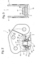
- Fig. 1
- Anschlussorgan an einer Luftfeder
- Fig. 2
- Seitenansicht mit Schnittdarstellung des Anschlussorgan
- Fig. 3
- Vorderansicht zur
Fig. 2 - Die
Fig. 1 zeigt ein Anschlussorgan 1 an einer Kolbenstange 3 einer Luftfeder 5. Der prinzipielle Aufbau einer Luftfeder wird als bekannt vorausgesetzt. Eine derartige Luftfeder wird z. B. für Fahrzeugachsen und Fahrerhauslagerungen eingesetzt. Entsprechend große Kräfte müssen von der Luftfeder aufgenommen werden. - Das Anschlussorgan verfügt über eine Grundplatte 7, die einteilig mit zwei parallelen Laschen 9; 11 ausgeführt ist. Ggf. kann das Anschlussorgan auch topfförmig geformt sein.
- Die Zusammenschau der
Fig. 2 und 3 zeigt eine Vergrößerung des Anschlussorgans 1. In der Grundplatte 7 ist eine Durchgangsöffnung 13 ausgeführt, die die Kolbenstange 3, z. B. die Kolbenstange eines Schwingungsdämpfers, aufnimmt. In den Laschen 9; 11 sind Durchgangsöffnungen 15 eingearbeitet, die zur Befestigung von nicht dargestellten Streben oder Bolzen dienen. Die Durchgangsöffnungen 15 müssen präzise zur Durchgangsöffnung 13 hergestellt werden, um eine günstige Krafteinleitung auf die Kolbenstange 3 zu gewährleisten. Deshalb wird das Anschlussorgan aus einer Blechplatine gefertigt, die sämtliche Durchgangsöffnungen aufweist. Danach werden die Laschen umgebogen. Abschließend wird die Durchgangsöffnung 13 nachgestanzt, um eine exakt runde Körperkontur zu erreichen. - In der Durchgangsöffnung 13 ist eine Gewindehülse 17 eingeschweißt. Die Gewindehülse weist einen Tragflansch 19 auf, der an einer Unterseite 21 der Grundplatte 7 anliegt. Als-Befestigungsmittel zwischen dem Anschlussorgan und der Gewindehülse, über die das Anschlussorgan mit der Stange in Wirkverbindung steht, dient eine Kehlnaht 23 zwischen dem Tragflansch und der Unterseite 21 der Grundplatte, die für eine Schweißvorrichtung gut zugänglich ist. Diese Schweißnaht wird getrennt von der Luftfeder ausgeführt, damit keinesfalls Spritzer einen Schaden anrichten können.
- Die Durchgangsöffnung 13 bildet mit der Gewindehülse einen Ringspalt 25, der von einem auf einer der Schweißnaht 23 abgewandten Oberseite 27 der Grundplatte 7 angeordnetem Dichtring 29 verschlossen wird.
- Der Dichtring 29 weist einen kreisringförmigen Querschnitt auf und ist in einer Ringnut 31 der Gewindehülse gegen die Oberseite 27 der Grundplatte 7 vorgespannt. Zur leichteren Montage des Dichtrings 29 verfügt die Gewindehülse über eine Aufweitschräge 35, so dass die Dichtung sehr leicht in die Ringnut 31 bewegt werden kann. Das Anschlussorgan 1 kann unabhängig von der Luftfeder hergestellt werden.
- In einem letzten Fertigungsschritt wird das Anschlussorgan 1 auf die Stange 3 geschraubt, die einen Gewindeansatz 33 für die Gewindehülse 17 aufweist. Die im rauhen Alltagsbetrieb anfallende Feuchtigkeit erreicht zwar das Anschlussorgan, dessen Oberfläche korrosionsgeschützt ist, kann jedoch nicht in den Ringspalt 25 eindringen, da der Dichtring 29 dieses verhindert.
Claims (5)
- Anschlussorgan (1) an eine Kolbenstange (3), umfassend eine Grundplatte (7) mit einer Durchgangsöffnung (13), wobei die Durchgangsöffnung (13) die Kolbenstange (3) aufnimmt und das Anschlussorgan (1) über Befestigungsmittel mit der Kolbenstange in Wirkverbindung steht und
ausgehend von der Grundplatte (7) zwei Laschen (9; 11) aufweist, dadurch gekennzeichnet dass als Befestigungsmittel in einer Durchgangsöffnung (13) der Grundplatte (7) eine Gewindehülse (7) zur Kolbenstange (3) eingeschweißt ist, wobei mindestens eine Schweißnaht (21) zwischen der Gewindehülse (7) und der Grundplatte (7) vorgesehen ist, die auf der den Laschen abgewandten Unterseite (21) der Grundplatte (7) ausgeführt ist und ein Dichtring (29) auf der der Schweißnaht (21) abgewandten Oberseite (27) der Grundplatte (7) einen Ringspalt (25) an der Durchgangsöffnung (13) verschließt. - Anschlussorgan nach Anspruch 1,
dadurch gekennzeichnet,
dass die Gewindehülse (17) einen Tragflansch (23) für die Grundplatte (7) aufweist. - Anschlussorgan nach Anspruch 1,
dadurch gekennzeichnet,
dass in der Gewindehülse (17) eine Ringnut (31) für den Dichtring (29) eingearbeitet ist. - Anschlussorgan nach Anspruch 1,
dadurch gekennzeichnet,
dass die Gewindehülse (17) eine Aufweitschräge (35) für den Dichtring (29) aufweist. - Anschlussorgan nach Anspruch 1,
dadurch gekennzeichnet,
dass die Dichtring (29) einen kreisförmigen Querschnitt aufweist.
Applications Claiming Priority (1)
| Application Number | Priority Date | Filing Date | Title |
|---|---|---|---|
| DE102005021764A DE102005021764B3 (de) | 2005-05-11 | 2005-05-11 | Anschlussorgan an eine Stange |
Publications (2)
| Publication Number | Publication Date |
|---|---|
| EP1722125A1 EP1722125A1 (de) | 2006-11-15 |
| EP1722125B1 true EP1722125B1 (de) | 2008-03-05 |
Family
ID=36888999
Family Applications (1)
| Application Number | Title | Priority Date | Filing Date |
|---|---|---|---|
| EP06008475A Expired - Lifetime EP1722125B1 (de) | 2005-05-11 | 2006-04-25 | Anschlussorgan an eine Stange |
Country Status (3)
| Country | Link |
|---|---|
| EP (1) | EP1722125B1 (de) |
| AT (1) | ATE388350T1 (de) |
| DE (2) | DE102005021764B3 (de) |
Families Citing this family (3)
| Publication number | Priority date | Publication date | Assignee | Title |
|---|---|---|---|---|
| CN104141656A (zh) * | 2014-07-12 | 2014-11-12 | 汤荣民 | 一种汽车悬挂系统连接件及其热处理工艺 |
| CN104141658A (zh) * | 2014-07-15 | 2014-11-12 | 汤荣民 | 一种汽车底盘连接件及其热处理工艺 |
| DE102014114730B4 (de) | 2014-10-10 | 2021-08-05 | Knorr-Bremse Systeme für Nutzfahrzeuge GmbH | Modulare Steuereinrichtung für ein Schaltgetriebe eines Nutzfahrzeuges |
Family Cites Families (11)
| Publication number | Priority date | Publication date | Assignee | Title |
|---|---|---|---|---|
| DE1016067B (de) * | 1953-11-17 | 1957-09-19 | Boge Gmbh | Befestigungsauge fuer Stossdaempfer |
| DE1924540A1 (de) * | 1969-05-14 | 1970-12-10 | Fichtel & Sachs Ag | Loetverbindung von hartverchromten Stangen mit unverchromten Muffen |
| JPS56162359U (de) * | 1980-05-02 | 1981-12-02 | ||
| DE8813045U1 (de) * | 1988-10-17 | 1988-12-29 | Fichtel & Sachs Ag, 97424 Schweinfurt | Luftfeder |
| JP3533411B2 (ja) * | 1996-07-01 | 2004-05-31 | 東洋ゴム工業株式会社 | ストラットマウントインシュレータ |
| FR2764659B1 (fr) * | 1997-06-13 | 2001-10-19 | Financy Sa | Tete d'amortisseur et son procede de fabrication |
| DE19805218A1 (de) * | 1998-02-10 | 1999-05-27 | Mannesmann Sachs Ag | Anschlußgelenk |
| DE10052788B4 (de) * | 1999-12-02 | 2010-10-07 | Stabilus Gmbh | Kolben-Zylinderaggregat mit einem Korrosionsschutz |
| DE10109627C1 (de) * | 2001-02-28 | 2002-10-31 | Zf Sachs Ag | Gelenkauge für ein Kolben-Zylinderaggregat |
| DE10344951B4 (de) * | 2003-09-27 | 2008-02-07 | Zf Friedrichshafen Ag | Gelenkauge für ein Kolben-Zylinderaggregat |
| DE10348971A1 (de) * | 2003-10-22 | 2005-05-25 | Zf Friedrichshafen Ag | Dämpfungselement |
-
2005
- 2005-05-11 DE DE102005021764A patent/DE102005021764B3/de not_active Expired - Fee Related
-
2006
- 2006-04-25 AT AT06008475T patent/ATE388350T1/de not_active IP Right Cessation
- 2006-04-25 DE DE502006000419T patent/DE502006000419D1/de not_active Expired - Lifetime
- 2006-04-25 EP EP06008475A patent/EP1722125B1/de not_active Expired - Lifetime
Also Published As
| Publication number | Publication date |
|---|---|
| DE502006000419D1 (de) | 2008-04-17 |
| EP1722125A1 (de) | 2006-11-15 |
| DE102005021764B3 (de) | 2007-02-22 |
| ATE388350T1 (de) | 2008-03-15 |
Similar Documents
| Publication | Publication Date | Title |
|---|---|---|
| DE102019202753B3 (de) | Karosseriestruktur für ein elektrisch betriebenes Fahrzeug | |
| DE102010036644B4 (de) | Aufhängungsarm | |
| DE102011086481B4 (de) | Fahrwerksystem für Nutzfahrzeuge | |
| DE102007035483A1 (de) | Crasheinrichtung | |
| EP2803512B1 (de) | Kugelgelenk und Kraftfahrzeug-Lenker | |
| DE102007012137A1 (de) | Crashbox und Kraftfahrzeug-Stoßfängeranordnung | |
| DE19719301A1 (de) | Aufbauseitige Lagerung eines Stoßdämpfers | |
| DE102021107065B4 (de) | Kraftfahrzeugträger mit einer Buchse | |
| DE19815215B4 (de) | Federbein mit Achsschenkel | |
| DE19803174A1 (de) | Kolben-Zylinderaggregat mit einem Führungslager | |
| DE102020211709A1 (de) | Sockelelement für dämpfer | |
| DE102019101718A1 (de) | Stoßfängeranordnung für ein Kraftfahrzeug | |
| EP3458289B1 (de) | Verfahren zur herstellung eines fahrzeugbauteils | |
| WO2022069655A1 (de) | Trägerstruktur für einen instrumententafelträger sowie instrumententafelträger mit einer solchen trägerstruktur | |
| DE10101738B4 (de) | Treibstoffbehälter für Kraftfahrzeuge | |
| DE102007030549A1 (de) | Kolben-Zylinderaggregat | |
| DE102010008179A1 (de) | Stoßdämpfergehäuse | |
| DE102014008402B4 (de) | Vorderwagenstruktur | |
| DE102005021764B3 (de) | Anschlussorgan an eine Stange | |
| EP1982900B1 (de) | Heckseitige Fahrzeugkarosseriestruktur | |
| DE112013003868T5 (de) | Stoßdämpfer | |
| EP3458290A1 (de) | Haltebock | |
| DE102013000630A1 (de) | Anordnung zur Befestigung eines ersten Bauteils an einem zweiten Bauteil | |
| DE102016103306A1 (de) | Achssystem | |
| EP1642085B1 (de) | Befestigungsvorrichtung für adaptierbare panzerungselemente |
Legal Events
| Date | Code | Title | Description |
|---|---|---|---|
| PUAI | Public reference made under article 153(3) epc to a published international application that has entered the european phase |
Free format text: ORIGINAL CODE: 0009012 |
|
| AK | Designated contracting states |
Kind code of ref document: A1 Designated state(s): AT BE BG CH CY CZ DE DK EE ES FI FR GB GR HU IE IS IT LI LT LU LV MC NL PL PT RO SE SI SK TR |
|
| AX | Request for extension of the european patent |
Extension state: AL BA HR MK YU |
|
| 17P | Request for examination filed |
Effective date: 20061027 |
|
| 17Q | First examination report despatched |
Effective date: 20070104 |
|
| 17Q | First examination report despatched |
Effective date: 20070104 |
|
| AKX | Designation fees paid |
Designated state(s): AT BE BG CH CY CZ DE DK EE ES FI FR GB GR HU IE IS IT LI LT LU LV MC NL PL PT RO SE SI SK TR |
|
| GRAP | Despatch of communication of intention to grant a patent |
Free format text: ORIGINAL CODE: EPIDOSNIGR1 |
|
| GRAS | Grant fee paid |
Free format text: ORIGINAL CODE: EPIDOSNIGR3 |
|
| GRAA | (expected) grant |
Free format text: ORIGINAL CODE: 0009210 |
|
| AK | Designated contracting states |
Kind code of ref document: B1 Designated state(s): AT BE BG CH CY CZ DE DK EE ES FI FR GB GR HU IE IS IT LI LT LU LV MC NL PL PT RO SE SI SK TR |
|
| REG | Reference to a national code |
Ref country code: GB Ref legal event code: FG4D Free format text: NOT ENGLISH |
|
| REG | Reference to a national code |
Ref country code: CH Ref legal event code: EP |
|
| REG | Reference to a national code |
Ref country code: IE Ref legal event code: FG4D Free format text: LANGUAGE OF EP DOCUMENT: GERMAN |
|
| REF | Corresponds to: |
Ref document number: 502006000419 Country of ref document: DE Date of ref document: 20080417 Kind code of ref document: P |
|
| REG | Reference to a national code |
Ref country code: SE Ref legal event code: TRGR |
|
| PG25 | Lapsed in a contracting state [announced via postgrant information from national office to epo] |
Ref country code: FI Free format text: LAPSE BECAUSE OF FAILURE TO SUBMIT A TRANSLATION OF THE DESCRIPTION OR TO PAY THE FEE WITHIN THE PRESCRIBED TIME-LIMIT Effective date: 20080305 Ref country code: ES Free format text: LAPSE BECAUSE OF FAILURE TO SUBMIT A TRANSLATION OF THE DESCRIPTION OR TO PAY THE FEE WITHIN THE PRESCRIBED TIME-LIMIT Effective date: 20080616 |
|
| ET | Fr: translation filed | ||
| PG25 | Lapsed in a contracting state [announced via postgrant information from national office to epo] |
Ref country code: PL Free format text: LAPSE BECAUSE OF FAILURE TO SUBMIT A TRANSLATION OF THE DESCRIPTION OR TO PAY THE FEE WITHIN THE PRESCRIBED TIME-LIMIT Effective date: 20080305 Ref country code: LV Free format text: LAPSE BECAUSE OF FAILURE TO SUBMIT A TRANSLATION OF THE DESCRIPTION OR TO PAY THE FEE WITHIN THE PRESCRIBED TIME-LIMIT Effective date: 20080305 Ref country code: SI Free format text: LAPSE BECAUSE OF FAILURE TO SUBMIT A TRANSLATION OF THE DESCRIPTION OR TO PAY THE FEE WITHIN THE PRESCRIBED TIME-LIMIT Effective date: 20080305 |
|
| REG | Reference to a national code |
Ref country code: IE Ref legal event code: FD4D |
|
| BERE | Be: lapsed |
Owner name: ZF FRIEDRICHSHAFEN A.G. Effective date: 20080430 |
|
| PG25 | Lapsed in a contracting state [announced via postgrant information from national office to epo] |
Ref country code: PT Free format text: LAPSE BECAUSE OF FAILURE TO SUBMIT A TRANSLATION OF THE DESCRIPTION OR TO PAY THE FEE WITHIN THE PRESCRIBED TIME-LIMIT Effective date: 20080805 Ref country code: CZ Free format text: LAPSE BECAUSE OF FAILURE TO SUBMIT A TRANSLATION OF THE DESCRIPTION OR TO PAY THE FEE WITHIN THE PRESCRIBED TIME-LIMIT Effective date: 20080305 Ref country code: SK Free format text: LAPSE BECAUSE OF FAILURE TO SUBMIT A TRANSLATION OF THE DESCRIPTION OR TO PAY THE FEE WITHIN THE PRESCRIBED TIME-LIMIT Effective date: 20080305 |
|
| PG25 | Lapsed in a contracting state [announced via postgrant information from national office to epo] |
Ref country code: MC Free format text: LAPSE BECAUSE OF NON-PAYMENT OF DUE FEES Effective date: 20080430 Ref country code: RO Free format text: LAPSE BECAUSE OF FAILURE TO SUBMIT A TRANSLATION OF THE DESCRIPTION OR TO PAY THE FEE WITHIN THE PRESCRIBED TIME-LIMIT Effective date: 20080305 |
|
| PG25 | Lapsed in a contracting state [announced via postgrant information from national office to epo] |
Ref country code: IS Free format text: LAPSE BECAUSE OF FAILURE TO SUBMIT A TRANSLATION OF THE DESCRIPTION OR TO PAY THE FEE WITHIN THE PRESCRIBED TIME-LIMIT Effective date: 20080705 |
|
| PLBE | No opposition filed within time limit |
Free format text: ORIGINAL CODE: 0009261 |
|
| STAA | Information on the status of an ep patent application or granted ep patent |
Free format text: STATUS: NO OPPOSITION FILED WITHIN TIME LIMIT |
|
| PG25 | Lapsed in a contracting state [announced via postgrant information from national office to epo] |
Ref country code: IE Free format text: LAPSE BECAUSE OF FAILURE TO SUBMIT A TRANSLATION OF THE DESCRIPTION OR TO PAY THE FEE WITHIN THE PRESCRIBED TIME-LIMIT Effective date: 20080305 Ref country code: EE Free format text: LAPSE BECAUSE OF FAILURE TO SUBMIT A TRANSLATION OF THE DESCRIPTION OR TO PAY THE FEE WITHIN THE PRESCRIBED TIME-LIMIT Effective date: 20080305 Ref country code: LT Free format text: LAPSE BECAUSE OF FAILURE TO SUBMIT A TRANSLATION OF THE DESCRIPTION OR TO PAY THE FEE WITHIN THE PRESCRIBED TIME-LIMIT Effective date: 20080305 Ref country code: DK Free format text: LAPSE BECAUSE OF FAILURE TO SUBMIT A TRANSLATION OF THE DESCRIPTION OR TO PAY THE FEE WITHIN THE PRESCRIBED TIME-LIMIT Effective date: 20080305 |
|
| 26N | No opposition filed |
Effective date: 20081208 |
|
| PG25 | Lapsed in a contracting state [announced via postgrant information from national office to epo] |
Ref country code: BE Free format text: LAPSE BECAUSE OF NON-PAYMENT OF DUE FEES Effective date: 20080430 |
|
| PG25 | Lapsed in a contracting state [announced via postgrant information from national office to epo] |
Ref country code: BG Free format text: LAPSE BECAUSE OF FAILURE TO SUBMIT A TRANSLATION OF THE DESCRIPTION OR TO PAY THE FEE WITHIN THE PRESCRIBED TIME-LIMIT Effective date: 20080605 |
|
| PG25 | Lapsed in a contracting state [announced via postgrant information from national office to epo] |
Ref country code: AT Free format text: LAPSE BECAUSE OF NON-PAYMENT OF DUE FEES Effective date: 20080425 |
|
| PG25 | Lapsed in a contracting state [announced via postgrant information from national office to epo] |
Ref country code: CY Free format text: LAPSE BECAUSE OF FAILURE TO SUBMIT A TRANSLATION OF THE DESCRIPTION OR TO PAY THE FEE WITHIN THE PRESCRIBED TIME-LIMIT Effective date: 20080305 |
|
| PG25 | Lapsed in a contracting state [announced via postgrant information from national office to epo] |
Ref country code: LU Free format text: LAPSE BECAUSE OF NON-PAYMENT OF DUE FEES Effective date: 20080425 Ref country code: HU Free format text: LAPSE BECAUSE OF FAILURE TO SUBMIT A TRANSLATION OF THE DESCRIPTION OR TO PAY THE FEE WITHIN THE PRESCRIBED TIME-LIMIT Effective date: 20080906 |
|
| PGFP | Annual fee paid to national office [announced via postgrant information from national office to epo] |
Ref country code: FR Payment date: 20100521 Year of fee payment: 5 |
|
| PG25 | Lapsed in a contracting state [announced via postgrant information from national office to epo] |
Ref country code: TR Free format text: LAPSE BECAUSE OF FAILURE TO SUBMIT A TRANSLATION OF THE DESCRIPTION OR TO PAY THE FEE WITHIN THE PRESCRIBED TIME-LIMIT Effective date: 20080305 |
|
| PGFP | Annual fee paid to national office [announced via postgrant information from national office to epo] |
Ref country code: IT Payment date: 20100422 Year of fee payment: 5 Ref country code: NL Payment date: 20100402 Year of fee payment: 5 |
|
| PG25 | Lapsed in a contracting state [announced via postgrant information from national office to epo] |
Ref country code: GR Free format text: LAPSE BECAUSE OF FAILURE TO SUBMIT A TRANSLATION OF THE DESCRIPTION OR TO PAY THE FEE WITHIN THE PRESCRIBED TIME-LIMIT Effective date: 20080606 |
|
| PGFP | Annual fee paid to national office [announced via postgrant information from national office to epo] |
Ref country code: SE Payment date: 20100409 Year of fee payment: 5 |
|
| REG | Reference to a national code |
Ref country code: CH Ref legal event code: PL |
|
| GBPC | Gb: european patent ceased through non-payment of renewal fee |
Effective date: 20100425 |
|
| PG25 | Lapsed in a contracting state [announced via postgrant information from national office to epo] |
Ref country code: LI Free format text: LAPSE BECAUSE OF NON-PAYMENT OF DUE FEES Effective date: 20100430 Ref country code: CH Free format text: LAPSE BECAUSE OF NON-PAYMENT OF DUE FEES Effective date: 20100430 |
|
| PG25 | Lapsed in a contracting state [announced via postgrant information from national office to epo] |
Ref country code: GB Free format text: LAPSE BECAUSE OF NON-PAYMENT OF DUE FEES Effective date: 20100425 |
|
| REG | Reference to a national code |
Ref country code: NL Ref legal event code: V1 Effective date: 20111101 |
|
| REG | Reference to a national code |
Ref country code: SE Ref legal event code: EUG |
|
| REG | Reference to a national code |
Ref country code: FR Ref legal event code: ST Effective date: 20111230 |
|
| PG25 | Lapsed in a contracting state [announced via postgrant information from national office to epo] |
Ref country code: NL Free format text: LAPSE BECAUSE OF NON-PAYMENT OF DUE FEES Effective date: 20111101 Ref country code: FR Free format text: LAPSE BECAUSE OF NON-PAYMENT OF DUE FEES Effective date: 20110502 |
|
| PG25 | Lapsed in a contracting state [announced via postgrant information from national office to epo] |
Ref country code: IT Free format text: LAPSE BECAUSE OF NON-PAYMENT OF DUE FEES Effective date: 20110425 |
|
| PG25 | Lapsed in a contracting state [announced via postgrant information from national office to epo] |
Ref country code: SE Free format text: LAPSE BECAUSE OF NON-PAYMENT OF DUE FEES Effective date: 20110426 |
|
| PGFP | Annual fee paid to national office [announced via postgrant information from national office to epo] |
Ref country code: DE Payment date: 20140430 Year of fee payment: 9 |
|
| REG | Reference to a national code |
Ref country code: DE Ref legal event code: R119 Ref document number: 502006000419 Country of ref document: DE |
|
| PG25 | Lapsed in a contracting state [announced via postgrant information from national office to epo] |
Ref country code: DE Free format text: LAPSE BECAUSE OF NON-PAYMENT OF DUE FEES Effective date: 20151103 |