EP1721848A2 - Wickelmaschine - Google Patents
Wickelmaschine Download PDFInfo
- Publication number
- EP1721848A2 EP1721848A2 EP06111262A EP06111262A EP1721848A2 EP 1721848 A2 EP1721848 A2 EP 1721848A2 EP 06111262 A EP06111262 A EP 06111262A EP 06111262 A EP06111262 A EP 06111262A EP 1721848 A2 EP1721848 A2 EP 1721848A2
- Authority
- EP
- European Patent Office
- Prior art keywords
- winding
- bed
- rolls
- guide heads
- holding devices
- Prior art date
- Legal status (The legal status is an assumption and is not a legal conclusion. Google has not performed a legal analysis and makes no representation as to the accuracy of the status listed.)
- Granted
Links
Images


Classifications
-
- B—PERFORMING OPERATIONS; TRANSPORTING
- B65—CONVEYING; PACKING; STORING; HANDLING THIN OR FILAMENTARY MATERIAL
- B65H—HANDLING THIN OR FILAMENTARY MATERIAL, e.g. SHEETS, WEBS, CABLES
- B65H19/00—Changing the web roll
- B65H19/22—Changing the web roll in winding mechanisms or in connection with winding operations
- B65H19/2238—The web roll being driven by a winding mechanism of the nip or tangential drive type
- B65H19/2246—The web roll being driven by a winding mechanism of the nip or tangential drive type and the roll being supported on two rollers
-
- B—PERFORMING OPERATIONS; TRANSPORTING
- B65—CONVEYING; PACKING; STORING; HANDLING THIN OR FILAMENTARY MATERIAL
- B65H—HANDLING THIN OR FILAMENTARY MATERIAL, e.g. SHEETS, WEBS, CABLES
- B65H18/00—Winding webs
- B65H18/02—Supporting web roll
- B65H18/023—Supporting web roll on its outer circumference
- B65H18/025—Parallel rollers type
-
- B—PERFORMING OPERATIONS; TRANSPORTING
- B65—CONVEYING; PACKING; STORING; HANDLING THIN OR FILAMENTARY MATERIAL
- B65H—HANDLING THIN OR FILAMENTARY MATERIAL, e.g. SHEETS, WEBS, CABLES
- B65H19/00—Changing the web roll
- B65H19/22—Changing the web roll in winding mechanisms or in connection with winding operations
- B65H19/2292—Removing cores or mandrels from web roll after winding
-
- B—PERFORMING OPERATIONS; TRANSPORTING
- B65—CONVEYING; PACKING; STORING; HANDLING THIN OR FILAMENTARY MATERIAL
- B65H—HANDLING THIN OR FILAMENTARY MATERIAL, e.g. SHEETS, WEBS, CABLES
- B65H19/00—Changing the web roll
- B65H19/22—Changing the web roll in winding mechanisms or in connection with winding operations
- B65H19/30—Lifting, transporting, or removing the web roll; Inserting core
-
- B—PERFORMING OPERATIONS; TRANSPORTING
- B65—CONVEYING; PACKING; STORING; HANDLING THIN OR FILAMENTARY MATERIAL
- B65H—HANDLING THIN OR FILAMENTARY MATERIAL, e.g. SHEETS, WEBS, CABLES
- B65H2301/00—Handling processes for sheets or webs
- B65H2301/40—Type of handling process
- B65H2301/41—Winding, unwinding
- B65H2301/414—Winding
- B65H2301/4148—Winding slitting
-
- B—PERFORMING OPERATIONS; TRANSPORTING
- B65—CONVEYING; PACKING; STORING; HANDLING THIN OR FILAMENTARY MATERIAL
- B65H—HANDLING THIN OR FILAMENTARY MATERIAL, e.g. SHEETS, WEBS, CABLES
- B65H2301/00—Handling processes for sheets or webs
- B65H2301/40—Type of handling process
- B65H2301/41—Winding, unwinding
- B65H2301/414—Winding
- B65H2301/4148—Winding slitting
- B65H2301/41485—Winding slitting winding on one single shaft or support
Definitions
- the invention relates to a double carrier roll winding machine for winding a plurality of partial webs formed by the longitudinal cutting of a material web, in particular a paper or board web, onto a plurality of winding tubes held by guide heads to adjacent winding rolls in a winding bed formed by two carrier rolls.
- Material webs must be wound up into shipping or finishing rolls before they can be shipped.
- reel cores usually winding cores are used, which are preferably made of cardboard.
- the finished rolls are produced by so-called mother or spool rolls, which are produced at the exit of a paper machine or after the calendering, unwound, cut in the longitudinal direction and then wound on each winding cores.
- mother or spool rolls which are produced at the exit of a paper machine or after the calendering, unwound, cut in the longitudinal direction and then wound on each winding cores.
- These cores lie in a winding bed formed by two support rollers of a double carrier roll winding machine.
- Such Doppeltragwalzen winding machine is for example from the DE 200 13 319 U1 or the EP 0 792 245 B1 known; at least one of the two support rollers is driven. In this way, according to the number of individual webs of material produced from the original material web by longitudinal cuts several winding cores next to each other in the winding bed.
- this object is achieved in a winding machine of the type mentioned above in that the double winder-winding machine comprises holding devices which can be moved before the complete pulling out of the guide heads from the winding tubes or before ejection from the winding bed to the outer end faces of the outer winding rolls or are arranged fixed to the side of the outer end faces.
- the holding devices must be placed on the end faces of the outer winding tubes. If the retraction of the guide heads can be done so carefully that during this process, a falling of the outer winding rollers is not to be feared, at least care must be taken that these bobbins do not fall over during ejection; Therefore, it must be ensured that the holding devices are positioned at the latest before the start of ejection on the end faces of the outer winding rollers.
- the holding device After completion of the ejection, the holding device can be removed again. It is irrelevant how the pivoting movement for attachment or removal of the holding device takes place or how the supporting elements are designed.
- the invention can be used in all types of known double winder winding machines.
- the holding devices can be formed advantageously as rings, plates or plates. It is particularly advantageous if the rings surround the guide heads concentrically.
- the holding devices can also be configured as strips; These can be attached with advantage above the guide heads.
- the strips are either arranged stationary, or they are moved up or pivoted, for example, during the winding process or shortly before moving out of the guide heads from the cores to the end faces of the cores.
- the invention also relates to a method of winding bobbins on adjacent winding tubes in a winding bed of a double winder winding machine, wherein the winding tubes are held by guide heads, and the common ejection of the wound bobbins from the winding bed after completion of the winding process by means of an ejector.
- the method according to the invention is characterized in that during winding or after winding holding devices are approached laterally on the outer end faces of the outer winding rollers that they can not fall over when ejected from the winding bed, that subsequently the guide heads are moved out of the cores and that then the bobbins are pushed out of the winding bed together.
- a winding device formed by a twin-winder winding machine ( Figures 1a, b, 4a, b) has two support rollers 1, 2, at least one of which is driven.
- the support rollers 1, 2 form a roller bed, in which a single or a plurality of adjacent winding rollers 3 rests on the support rollers 1, 2 during winding.
- the winding rollers 3 are held on both end faces in each case via guide heads 4, which engage in the winding tubes, on which the winding rollers 3 are wound.
- a ring 5 is arranged in each case, which can be applied to an outer end face 6.
- the application is made either before pulling out the guide head 4 from the winding tube or synchronously with the pulling out of the guide head 4 ( Figure 2a, b, Figure 5a, b).
- an ejection device 7 (Fig. 3a, b, Fig. 6a, b) pushes the winding rollers 3 out of the winding bed by moving the ejection device in the direction of an arrow A.
- the ring 5 remains in position (FIGS. 7a, b).
- a bar 8 is provided, which is positioned above the guide head 4 and rest against the end face 6 of the winding rollers 3 before or during extraction of the guide head 4 leaves.
- the strip 8 is also pushed towards the end face 6 in relation to its initial position (FIG. 8 a, b) (FIGS. 9 a, b).
- the ejection device 7 in the direction of Arrow A is pressed against the winding rollers 3, to push them out of the winding bed.
Landscapes
- Replacement Of Web Rolls (AREA)
- Spinning Methods And Devices For Manufacturing Artificial Fibers (AREA)
Abstract
Description
- Die Erfindung bezieht sich auf eine Doppeltragwalzen-Wickelmaschine zum Aufwickeln mehrerer durch das Längsschneiden einer Materialbahn, insbesondere einer Papier- oder Kartonbahn, entstandener Teilbahnen auf eine Mehrzahl von durch Führungsköpfe gehaltene Wickelhülsen zu nebeneinanderliegenden Wickelrollen in einem von zwei Tragwalzen gebildeten Wickelbett.
- Materialbahnen müssen, bevor sie versandt werden können, zu Versand- oder Fertigrollen aufgewickelt werden. Als Rollenkerne werden hierfür üblicherweise Wickelhülsen verwendet, die vorzugsweise aus Pappe bestehen. Die Fertigrollen werden dadurch erzeugt, dass sogenannte Mutter- oder Tambourrollen, die am Ausgang einer Papiermaschine oder nach der Satinage erzeugt werden, abgewickelt, in Längsrichtung geschnitten und dann jeweils auf Wickelhülsen aufgewickelt werden. Diese Wickelhülsen liegen in einem von zwei Tragrollen einer Doppeltragwalzen-Wickelmaschine gebildeten Wickelbett.
- Eine derartige Doppeltragwalzen-Wickelmaschine ist beispielsweise aus der
DE 200 13 319 U1 oder derEP 0 792 245 B1 bekannt; mindestens eine der beiden Tragwalzen ist angetrieben. Auf diese Weise liegen entsprechend der Anzahl der aus der ursprünglichen Materialbahn durch Längsschnitte erzeugten einzelnen Materialbahnen mehrere Wickelhülsen nebeneinander in dem Wickelbett. - Besonders wenn verhältnismäßig schmale Wickelrollen gewickelt werden, besteht das Problem, dass die äußeren der Wickelrollen zu den Stirnseiten hin umkippen, weil sie keine ausreichende Stabilität haben, während die Führungsköpfe aus den äußeren Wickelhülsen herausfahren oder während die Wickelrollen durch eine Ausstoßvorrichtung aus dem Wickelbett herausgedrückt werden.
- Es ist die Aufgabe der Erfindung, eine verbesserte Wickelmaschine zu schaffen, bei der das Kippen der randseitigen Wickelrollen beim Herausziehen der Führungsköpfe und beim Ausstoßen aus dem Wickelbett verhindert wird.
- Erfindungsgemäß wird diese Aufgabe bei einer Wickelmaschine der eingangs genannten Art dadurch gelöst, dass die Doppeltragwalzen-Wickelmaschine Haltevorrichtungen umfasst, die vor dem vollständigen Herausziehen der Führungsköpfe aus den Wickelhülsen oder vor dem Ausstoßen aus dem Wickelbett an die äußeren Stirnseiten der äußeren Wickelrollen heranführbar sind oder die ortsfest seitlich der äußeren Stirnseiten angeordnet sind.
- Wenigstens vor der Beendigung des Herausfahrens der Führungsköpfe aus den Wickelhülsen müssen die Haltevorrichtungen an den Stirnseiten der äußeren Wickelhülsen plaziert sein. Sofern das Herausfahren der Führungsköpfe so vorsichtig geschehen kann, dass während dieses Vorgangs ein Umfallen der äußeren Wickelrollen nicht zu befürchten ist, muss wenigstens dafür Sorge getragen werden, dass diese Wickelrollen nicht während des Ausstoßens umfallen; daher muss gewährleistet sein, dass die Haltevorrichtungen spätestens vor Beginn des Ausstoßens an den Stirnseiten der äußeren Wickelrollen positioniert sind.
- Nach Beendigung des Ausstoßens kann die Haltevorrichtung wieder entfernt werden. Es ist ohne Bedeutung, wie die Schwenkbewegung zum Anbringen oder zum Entfernen der Haltevorrichtung erfolgt oder wie die abstützenden Elemente gestaltet sind. Die Erfindung kann in allen Arten von bekannten Doppeltragwalzen-Wickelmaschinen eingesetzt werden.
- Vorteilhafte Weiterbildungen ergeben sich aus den Unteransprüchen, der Beschreibung und den Zeichnungen.
- Die Haltevorrichtungen lassen sich in vorteilhafter Weise jeweils als Ringe, Teller oder Platten ausbilden. Von besonderem Vorteil ist es, wenn die Ringe die Führungsköpfe konzentrisch umgeben.
- Alternativ lassen sich die Haltevorrichtungen auch jeweils als Leisten ausgestalten; diese lassen sich mit Vorteil oberhalb der Führungsköpfe anbringen. Die Leisten sind entweder ortsfest angeordnet, oder sie werden beispielsweise während des Wickelvorgangs oder kurz vor dem Herausfahren der Führungsköpfe aus den Wickelhülsen an die Stirnseiten der Wickelhülsen herangefahren oder herangeschwenkt.
- Die Erfindung bezieht sich auch auf ein Verfahren zum Aufwickeln von Wickelrollen auf nebeneinanderliegenden Wickelhülsen in einem Wickelbett einer Doppeltragwalzen-Wickelmaschine, wobei die Wickelhülsen durch Führungsköpfe gehalten werden, und zum gemeinsamen Ausstoßen der aufgewickelten Wickelrollen aus dem Wickelbett nach Beendigung des Wickelvorgangs mittels einer Ausstoßvorrichtung.
- Das Verfahren ist erfindungsgemäß dadurch gekennzeichnet, dass während des Aufwickelns oder nach dem Aufwickeln Haltevorrichtungen seitlich an die äußeren Stirnseiten der äußeren Wickelrollen soweit herangefahren werden, dass diese beim Ausstoßen aus dem Wickelbett nicht umfallen können, dass anschließend die Führungsköpfe aus den Wickelhülsen herausgefahren werden und dass dann die Wickelrollen gemeinsam aus dem Wickelbett herausgestoßen werden.
- Nachstehend wird die Erfindung in Ausführungsbeispielen anhand der Zeichnungen näher erläutert.
- Es zeigen
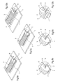
- Fig. 1a - 7b
- verschiedene Ansichten einer Doppeltragwalzen-Wickelmaschine vor dem Ausstoßen mehrerer nebeneinander gewickelter Wickelrollen und während des Ausstoßens unter Einsatz eines zu einem Führungskopf konzentrischen Tellers als Haltevorrichtung zum stirnseitigen Halten der äußeren Wickelrolle und
- Fig. 8a - 10b
- verschiedene Ansichten einer Doppeltragwalzen-Wickelmaschine, bei der während des Ausstoßens eine Leiste eingesetzt wird.
- Eine von einer Doppeltragwalzen-Wickelmaschine (Fig. 1a, b; Fig. 4a, b) gebildete Wickelvorrichtung weist zwei Tragwalzen 1, 2 auf, von denen mindestens eine angetrieben ist. Die Tragwalzen 1, 2 bilden ein Walzenbett, in dem eine einzige oder eine Mehrzahl von nebeneinander liegenden Wickelrollen 3 während des Aufwickelns auf den Tragwalzen 1, 2 aufliegt.
- Während des Wickelns werden die Wickelrollen 3 an beiden Stirnseiten jeweils über Führungsköpfe 4 gehalten, die in die Wickelhülsen eingreifen, auf die die Wickelrollen 3 aufgewickelt werden.
- Konzentrisch zu dem Führungskopf 4 ist jeweils ein Ring 5 angeordnet, der sich an eine äußere Stirnseite 6 anlegen lässt. Das Anlegen geschieht entweder vor dem Herausziehen des Führungskopfs 4 aus der Wickelhülse oder synchron mit dem Herausziehen des Führungskopfs 4 (Fig. 2a, b; Fig. 5a, b).
- Anschließend drückt eine Ausstoßvorrichtung 7 (Fig. 3a, b; Fig. 6a, b) die Wickelrollen 3 aus dem Wickelbett heraus, indem sich die Ausstoßvorrichtung in Richtung eines Pfeils A bewegt. Dabei bleibt der Ring 5 an seiner Position (Fig. 7a, b).
- In einer anderen Ausführungsform der Erfindung (Fig. 8a - Fig. 10b) ist anstelle des Rings 5 eine Leiste 8 vorgesehen, die oberhalb des Führungskopfs 4 positioniert ist und sich vor oder während des Herausziehens des Führungskopfs 4 an die Stirnseite 6 der Wickelrollen 3 anlegen lässt. Auch die Leiste 8 wird ähnlich wie der Ring 5 gegenüber seiner Anfangsposition (Fig. 8a, b) an die Stirnseite 6 herangeschoben (Fig. 9a, b). Anschließend wird nach dem Herausfahren des Führungskopfs 4 die Ausstoßvorrichtung 7 in Richtung des Pfeils A gegen die Wickelrollen 3 gedrückt, um diese aus dem Wickelbett herauszustoßen.
-
- 1
- Tragwalze
- 2
- Tragwalze
- 3
- Wickelrolle
- 4
- Führungskopf
- 5
- Ring
- 6
- Stirnseite
- 7
- Ausstoßvorrichtung
- 8
- Leiste
Claims (6)
- Doppeltragwalzen-Wickelmaschine zum Aufwickeln mehrerer durch das Längsschneiden einer Materialbahn, insbesondere einer Papier- oder Kartonbahn, entstandener Teilbahnen auf eine Mehrzahl von durch Führungsköpfe (4) gehaltene Wickelhülsen zu nebeneinanderliegenden Wickelrollen (3) in einem von zwei Tragwalzen (1, 2) gebildeten Wickelbett,
dadurch gekennzeichnet,
dass die Doppeltragwalzen-Wickelmaschine Haltevorrichtungen (5, 8) umfasst, die vor dem vollständigen Herausziehen der Führungsköpfe (4) aus den Wickelhülsen oder vor dem Ausstoßen aus dem Wickelbett an die äußeren Stirnseiten der äußeren Wickelrollen (3) heranführbar sind oder die ortsfest seitlich der äußeren Stirnseiten (6) der Wickelrollen (3) angeordnet sind. - Doppeltragwalzen-Wickelmaschine nach Anspruch 1,
dadurch gekennzeichnet,
dass die Haltevorrichtungen jeweils als Ringe (5), Teller oder Platten ausgebildet sind. - Doppeltragwalzen-Wickelmaschine nach Anspruch 2,
dadurch gekennzeichnet,
dass die Ringe (5) die Führungsköpfe (4) konzentrisch umgeben. - Doppeltragwalzen-Wickelmaschine nach Anspruch 1,
dadurch gekennzeichnet,
dass die Haltevorrichtungen jeweils als Leisten (8) ausgebildet sind. - Doppeltragwalzen-Wickelmaschine nach Anspruch 4,
dadurch gekennzeichnet,
dass die Haltevorrichtungen (8) ortsfest oberhalb der Führungsköpfe (4) angeordnet sind. - Verfahren zum Aufwickeln von Wickelrollen (3) auf nebeneinanderliegenden Wickelhülsen in einem Wickelbett einer Doppeltragwalzen-Wickelmaschine, wobei die Wickelhülsen durch Führungsköpfe (4) gehalten werden, und zum gemeinsamen Ausstoßen der aufgewickelten Wickelrollen (3) aus dem Wickelbett nach Beendigung des Wickelvorgangs mittels einer Ausstoßvorrichtung (7),
dadurch gekennzeichnet,
dass während des Aufwickelns oder nach dem Aufwickeln Haltevorrichtungen (5, 8) seitlich an die äußeren Stirnseiten (6) der äußeren Wickelrollen (3) soweit herangefahren werden, dass diese beim Ausstoßen aus dem Wickelbett nicht umfallen können, dass anschließend die Führungsköpfe (4) aus den Wickelhülsen herausgefahren werden und dass dann die Wickelrollen (3) gemeinsam aus dem Wickelbett herausgestoßen werden.
Applications Claiming Priority (1)
| Application Number | Priority Date | Filing Date | Title |
|---|---|---|---|
| DE102005000057A DE102005000057A1 (de) | 2005-05-11 | 2005-05-11 | Wickelmaschine |
Publications (3)
| Publication Number | Publication Date |
|---|---|
| EP1721848A2 true EP1721848A2 (de) | 2006-11-15 |
| EP1721848A3 EP1721848A3 (de) | 2007-07-18 |
| EP1721848B1 EP1721848B1 (de) | 2008-07-16 |
Family
ID=36687992
Family Applications (1)
| Application Number | Title | Priority Date | Filing Date |
|---|---|---|---|
| EP06111262A Expired - Lifetime EP1721848B1 (de) | 2005-05-11 | 2006-03-16 | Wickelmaschine |
Country Status (3)
| Country | Link |
|---|---|
| EP (1) | EP1721848B1 (de) |
| AT (1) | ATE401279T1 (de) |
| DE (2) | DE102005000057A1 (de) |
Family Cites Families (5)
| Publication number | Priority date | Publication date | Assignee | Title |
|---|---|---|---|---|
| US4040574A (en) * | 1976-03-10 | 1977-08-09 | Mobil Oil Corporation | Method and apparatus for replacing a roll of polystyrene foam sheet with empty core roll |
| JP3609170B2 (ja) * | 1995-10-05 | 2005-01-12 | 富士写真フイルム株式会社 | ウェブ巻取装置 |
| DE19743070A1 (de) * | 1997-09-30 | 1999-04-01 | Jagenberg Papiertech Gmbh | Tragwalzen-Wickelmaschine |
| FI111927B (fi) * | 2000-03-07 | 2003-10-15 | Metso Paper Inc | Menetelmä ja laite paperirainan kiinnirullauksessa |
| AU2002250124A1 (en) * | 2002-02-20 | 2003-09-09 | Personalizados De Jacarei, Ltda. | Multiple continuous supply rolls and high speed method and apparatus to produce them |
-
2005
- 2005-05-11 DE DE102005000057A patent/DE102005000057A1/de not_active Withdrawn
-
2006
- 2006-03-16 EP EP06111262A patent/EP1721848B1/de not_active Expired - Lifetime
- 2006-03-16 DE DE502006001101T patent/DE502006001101D1/de not_active Expired - Lifetime
- 2006-03-16 AT AT06111262T patent/ATE401279T1/de active
Also Published As
| Publication number | Publication date |
|---|---|
| DE502006001101D1 (de) | 2008-08-28 |
| EP1721848A3 (de) | 2007-07-18 |
| ATE401279T1 (de) | 2008-08-15 |
| DE102005000057A1 (de) | 2006-11-16 |
| EP1721848B1 (de) | 2008-07-16 |
Similar Documents
| Publication | Publication Date | Title |
|---|---|---|
| DE3243994C2 (de) | Wickelmaschine zum Aufwickeln einer längsgeteilten Bahn | |
| DE69916444T2 (de) | Wickelmaschine zum Formen von Rollen grossen Durchmessers aus Bahnmaterial mit Mitteln zum Einschieben einer Hülse | |
| DE2930474C2 (de) | Doppeltragwalzentwickelmaschine | |
| DE4334029A1 (de) | Tragwalzen-Wickelmaschine | |
| EP0887294B1 (de) | Wickelmaschine | |
| DE60022117T2 (de) | Vorrichtung und Verfahren zum Aufwickeln von Rollen | |
| EP2803609B1 (de) | Maschine zum Aufwickeln von bahnförmigen Materialien | |
| EP0829439A1 (de) | Verfahren zum Aufwickeln einer längsgeschnittenen Materialbahn und Vorrichtung zum Durchführen des Verfahrens | |
| EP1108669A2 (de) | Rollenwickelvorrichtung, insbesondere für eine Rollenschneidmaschine | |
| EP1721848B1 (de) | Wickelmaschine | |
| EP0382898A2 (de) | Tragwalzen-Wickelmaschine zum Aufwickeln von Materialbahnen | |
| EP0896940B1 (de) | Wickelvorrichtung, insbesondere in einem Rollenschneider | |
| EP0887297A2 (de) | Wickeleinrichtung für eine Materialbahn, insbesondere für eine Rollenschneidvorrichtung | |
| DE19837981A1 (de) | Verfahren und Vorrichtung zum Verpacken von Materialbahnrollen | |
| DE2838563C2 (de) | Vorrichtung zum Erzielen festgewickelter Bunde gleichen Durchmessers beim Aufwickeln mehrerer Schmalbänder | |
| EP0886620B1 (de) | Vorrichtung zur kontinuierlichen aufrollung von längsgeschnittenen papierbahnen mit automatischem rollenwechsel bei maschinengeschwindigkeit | |
| DE2414564C3 (de) | Vorrichtung zum Quertrennen von kontinuierlich ablaufenden, in Abständen zur Ausbildung von AbreiBschwächungsUnien quer perforierten Werkstoffbahnen | |
| DE102005000117A1 (de) | Rollenwickelvorrichtung | |
| EP1757545B1 (de) | Rollenwickelvorrichtung | |
| DE102005000051A1 (de) | Rollenwickelvorrichtung | |
| EP1657193B1 (de) | Rollenwickelvorrichtung und Verfahren zum Erzeugen von Wickelrollen | |
| EP2301871B1 (de) | Verfahren und Vorrichtung zur Hülsenbeschickung von Doppeltragwalzenrollern bei laufendem Betrieb | |
| DE3018269C2 (de) | Verfahren zum Anwickeln des Bahnanfangs an eine Wickelhülse einer Wickelmaschine und Wickelmaschine zur Durchführung des Verfahrens | |
| DE102004054987A1 (de) | Rollenwickelvorrichtung und Verfahren zum Erzeugen von Wickelrollen | |
| DE3914432A1 (de) | Mit indentifikationsmerkmalen bedruckter verschlussklebestreifen fuer aufzeichnungstraeger |
Legal Events
| Date | Code | Title | Description |
|---|---|---|---|
| PUAI | Public reference made under article 153(3) epc to a published international application that has entered the european phase |
Free format text: ORIGINAL CODE: 0009012 |
|
| AK | Designated contracting states |
Kind code of ref document: A2 Designated state(s): AT BE BG CH CY CZ DE DK EE ES FI FR GB GR HU IE IS IT LI LT LU LV MC NL PL PT RO SE SI SK TR |
|
| AX | Request for extension of the european patent |
Extension state: AL BA HR MK YU |
|
| PUAL | Search report despatched |
Free format text: ORIGINAL CODE: 0009013 |
|
| AK | Designated contracting states |
Kind code of ref document: A3 Designated state(s): AT BE BG CH CY CZ DE DK EE ES FI FR GB GR HU IE IS IT LI LT LU LV MC NL PL PT RO SE SI SK TR |
|
| AX | Request for extension of the european patent |
Extension state: AL BA HR MK YU |
|
| 17P | Request for examination filed |
Effective date: 20070821 |
|
| GRAP | Despatch of communication of intention to grant a patent |
Free format text: ORIGINAL CODE: EPIDOSNIGR1 |
|
| GRAS | Grant fee paid |
Free format text: ORIGINAL CODE: EPIDOSNIGR3 |
|
| AKX | Designation fees paid |
Designated state(s): AT DE FI IT |
|
| GRAA | (expected) grant |
Free format text: ORIGINAL CODE: 0009210 |
|
| AK | Designated contracting states |
Kind code of ref document: B1 Designated state(s): AT DE FI IT |
|
| REF | Corresponds to: |
Ref document number: 502006001101 Country of ref document: DE Date of ref document: 20080828 Kind code of ref document: P |
|
| PG25 | Lapsed in a contracting state [announced via postgrant information from national office to epo] |
Ref country code: FI Free format text: LAPSE BECAUSE OF FAILURE TO SUBMIT A TRANSLATION OF THE DESCRIPTION OR TO PAY THE FEE WITHIN THE PRESCRIBED TIME-LIMIT Effective date: 20080716 |
|
| PLBE | No opposition filed within time limit |
Free format text: ORIGINAL CODE: 0009261 |
|
| STAA | Information on the status of an ep patent application or granted ep patent |
Free format text: STATUS: NO OPPOSITION FILED WITHIN TIME LIMIT |
|
| 26N | No opposition filed |
Effective date: 20090417 |
|
| PGRI | Patent reinstated in contracting state [announced from national office to epo] |
Ref country code: FI Effective date: 20090828 |
|
| PGFP | Annual fee paid to national office [announced via postgrant information from national office to epo] |
Ref country code: DE Payment date: 20120323 Year of fee payment: 7 |
|
| PGFP | Annual fee paid to national office [announced via postgrant information from national office to epo] |
Ref country code: FI Payment date: 20120313 Year of fee payment: 7 Ref country code: IT Payment date: 20120319 Year of fee payment: 7 |
|
| PGFP | Annual fee paid to national office [announced via postgrant information from national office to epo] |
Ref country code: AT Payment date: 20120313 Year of fee payment: 7 |
|
| PG25 | Lapsed in a contracting state [announced via postgrant information from national office to epo] |
Ref country code: FI Free format text: LAPSE BECAUSE OF FAILURE TO SUBMIT A TRANSLATION OF THE DESCRIPTION OR TO PAY THE FEE WITHIN THE PRESCRIBED TIME-LIMIT Effective date: 20130316 |
|
| REG | Reference to a national code |
Ref country code: AT Ref legal event code: MM01 Ref document number: 401279 Country of ref document: AT Kind code of ref document: T Effective date: 20130316 |
|
| REG | Reference to a national code |
Ref country code: DE Ref legal event code: R119 Ref document number: 502006001101 Country of ref document: DE Effective date: 20131001 |
|
| PG25 | Lapsed in a contracting state [announced via postgrant information from national office to epo] |
Ref country code: DE Free format text: LAPSE BECAUSE OF NON-PAYMENT OF DUE FEES Effective date: 20131001 Ref country code: AT Free format text: LAPSE BECAUSE OF NON-PAYMENT OF DUE FEES Effective date: 20130316 |
|
| PG25 | Lapsed in a contracting state [announced via postgrant information from national office to epo] |
Ref country code: IT Free format text: LAPSE BECAUSE OF NON-PAYMENT OF DUE FEES Effective date: 20130316 |