EP1721592B1 - Rollstühle - Google Patents
Rollstühle Download PDFInfo
- Publication number
- EP1721592B1 EP1721592B1 EP06252484.8A EP06252484A EP1721592B1 EP 1721592 B1 EP1721592 B1 EP 1721592B1 EP 06252484 A EP06252484 A EP 06252484A EP 1721592 B1 EP1721592 B1 EP 1721592B1
- Authority
- EP
- European Patent Office
- Prior art keywords
- mounting
- assembly
- base frame
- connecting member
- interconnection arrangement
- Prior art date
- Legal status (The legal status is an assumption and is not a legal conclusion. Google has not performed a legal analysis and makes no representation as to the accuracy of the status listed.)
- Not-in-force
Links
Images


Classifications
-
- A—HUMAN NECESSITIES
- A61—MEDICAL OR VETERINARY SCIENCE; HYGIENE
- A61G—TRANSPORT, PERSONAL CONVEYANCES, OR ACCOMMODATION SPECIALLY ADAPTED FOR PATIENTS OR DISABLED PERSONS; OPERATING TABLES OR CHAIRS; CHAIRS FOR DENTISTRY; FUNERAL DEVICES
- A61G5/00—Chairs or personal conveyances specially adapted for patients or disabled persons, e.g. wheelchairs
- A61G5/10—Parts, details or accessories
- A61G5/1056—Arrangements for adjusting the seat
- A61G5/1059—Arrangements for adjusting the seat adjusting the height of the seat
-
- A—HUMAN NECESSITIES
- A61—MEDICAL OR VETERINARY SCIENCE; HYGIENE
- A61G—TRANSPORT, PERSONAL CONVEYANCES, OR ACCOMMODATION SPECIALLY ADAPTED FOR PATIENTS OR DISABLED PERSONS; OPERATING TABLES OR CHAIRS; CHAIRS FOR DENTISTRY; FUNERAL DEVICES
- A61G5/00—Chairs or personal conveyances specially adapted for patients or disabled persons, e.g. wheelchairs
- A61G5/10—Parts, details or accessories
- A61G5/1056—Arrangements for adjusting the seat
- A61G5/1067—Arrangements for adjusting the seat adjusting the backrest relative to the seat portion
-
- A—HUMAN NECESSITIES
- A61—MEDICAL OR VETERINARY SCIENCE; HYGIENE
- A61G—TRANSPORT, PERSONAL CONVEYANCES, OR ACCOMMODATION SPECIALLY ADAPTED FOR PATIENTS OR DISABLED PERSONS; OPERATING TABLES OR CHAIRS; CHAIRS FOR DENTISTRY; FUNERAL DEVICES
- A61G5/00—Chairs or personal conveyances specially adapted for patients or disabled persons, e.g. wheelchairs
- A61G5/10—Parts, details or accessories
- A61G5/1056—Arrangements for adjusting the seat
- A61G5/1075—Arrangements for adjusting the seat tilting the whole seat backwards
-
- A—HUMAN NECESSITIES
- A61—MEDICAL OR VETERINARY SCIENCE; HYGIENE
- A61G—TRANSPORT, PERSONAL CONVEYANCES, OR ACCOMMODATION SPECIALLY ADAPTED FOR PATIENTS OR DISABLED PERSONS; OPERATING TABLES OR CHAIRS; CHAIRS FOR DENTISTRY; FUNERAL DEVICES
- A61G5/00—Chairs or personal conveyances specially adapted for patients or disabled persons, e.g. wheelchairs
- A61G5/10—Parts, details or accessories
- A61G5/1081—Parts, details or accessories with shock absorbers or other suspension arrangements between frame and seat
-
- A—HUMAN NECESSITIES
- A61—MEDICAL OR VETERINARY SCIENCE; HYGIENE
- A61G—TRANSPORT, PERSONAL CONVEYANCES, OR ACCOMMODATION SPECIALLY ADAPTED FOR PATIENTS OR DISABLED PERSONS; OPERATING TABLES OR CHAIRS; CHAIRS FOR DENTISTRY; FUNERAL DEVICES
- A61G5/00—Chairs or personal conveyances specially adapted for patients or disabled persons, e.g. wheelchairs
- A61G5/10—Parts, details or accessories
- A61G5/12—Rests specially adapted therefor, e.g. for the head or the feet
- A61G5/125—Rests specially adapted therefor, e.g. for the head or the feet for arms
-
- A—HUMAN NECESSITIES
- A61—MEDICAL OR VETERINARY SCIENCE; HYGIENE
- A61G—TRANSPORT, PERSONAL CONVEYANCES, OR ACCOMMODATION SPECIALLY ADAPTED FOR PATIENTS OR DISABLED PERSONS; OPERATING TABLES OR CHAIRS; CHAIRS FOR DENTISTRY; FUNERAL DEVICES
- A61G5/00—Chairs or personal conveyances specially adapted for patients or disabled persons, e.g. wheelchairs
- A61G5/10—Parts, details or accessories
- A61G5/12—Rests specially adapted therefor, e.g. for the head or the feet
- A61G5/128—Rests specially adapted therefor, e.g. for the head or the feet for feet
Definitions
- This invention concerns improvements in or relating to wheelchairs, and particularly but not exclusively wheelchair chassis.
- wheelchairs which are specifically designed or adapted to meet the particular requirements of a user. This may for instance mean having an appropriate seating arrangement for a particular person and/or their disability. In some cases it is appropriate, or at least desirable, to provide a tilt option on a wheelchair. However, to provide bespoke wheelchairs for each user would involve considerable costs, and this option is therefore not available for many people.
- the apparatus disclosed by US 5727802 includes an interconnection arrangement between the upper and lower base frames comprising a shock absorber. This document does not though show a wheelchair including first and second mounting points for mounting an interconnection permitting tilting, and third and fourth mounting points for mounting a rigid interconnection.
- a wheelchair chassis assembly including a lower base frame which can mount ground engaging wheels, an upper base frame which can mount a seat arrangement, and a selectively removable interconnection arrangement between the lower and upper base frames, the interconnection arrangement being in either one of two forms, the first form providing a substantially rigid connection between the lower and upper base frames, and the second form permitting selective tilting between the lower and upper base frames about an axis towards the front of the assembly, characterised in that the second form of the interconnection arrangement comprises a variable length connecting member, the assembly including a first mounting point on the upper base frame toward the rear of the assembly for mounting a first end of the second form of the interconnection arrangement, a second mounting point on the lower base frame for mounting a second end of the second form of the interconnection arrangement, a third mounting point on the upper base frame toward the rear of the assembly for mounting a first end of the first form of the interconnection arrangement, and a fourth mounting point on the lower base frame for mounting a second end of the first form of the interconnection arrangement
- the first and second forms of the interconnection arrangement may include a front connecting member locatable towards the front of the wheelchair and which is substantially rigidly mounted to a one of the lower or upper base frames, and which is pivotally mounted to the other of the lower or upper base frames.
- the front connecting member is preferably pivotally mounted to the lower base frame.
- the first form of the interconnection arrangement preferably includes a substantially rigid rear connecting member which is selectively mountable to the lower and upper base frames to extend therebetween, towards the rear of the wheelchair.
- a plurality of selectable mounting positions for the rear connecting member may be provided to permit a selected one of a plurality of different inclinations between the lower and upper base frames to be chosen.
- variable length connecting member may be in the form of a piston and cylinder, and may include a gas strut.
- a hydraulic actuator may be provided for changing the length of the variable length connecting member.
- Means may be provided for selectively locking the variable length connecting member at a required length.
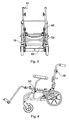
- the drawings show a wheelchair chassis 10 suitable for mounting a wide variety of seat arrangements (not shown aside from a chassis member therefor).
- the chassis 10 comprises a lower base frame 12 and an upper base frame 14.
- the lower base frame 12 is made of tubular components with side frames 16 interconnected at the front by a cross member 18 in the form of two Y's joined by their stems, and interconnected at the rear by a cross member 20.
- Each side frame 16 mounts a front wheel 22 on a swivel 24, and a larger rear wheel 26.
- a brake 28 with an operating lever 30 is provided for each wheel 26.
- the upper base frame 14 includes a generally square lower part 32 with side members 34 joined by cross members 36.
- a handle assembly extends from the rear of the cross members 36 and comprises a first upwardly extending portion 38.
- a shaped elongate member 40 extends from the portion 38 on each side and is joined by a cross member 42.
- the members 40 are pivotally mounted to the portions 38 by joints 44. In use the members 40 extend from the portions 38 in a generally parallel configuration. The members 40 can be held in this configuration by clips 45. When the chassis 10 is not in use, the clips 45 can be released, and the members 40 pivotted forwards onto the part 32, for storage and transportation.
- Cranked handle members 46 telescopically locate in the upper ends of the elongate members 40, and the height of the handle members 46 can be adjusted as illustrated at 47 in Fig. 1 to a required height for a person pushing the wheelchair.
- a locking nut 48 is provided for retaining the handle members 46 at a required height.
- Grips 49 are provided on the end of the handle members 46.
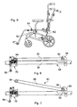
- the arrangement 50 includes a pair of front brackets 52, one on each side of the chassis 10 towards the front thereof.
- the front brackets 52 comprise shaped strips which extend with a generally U-shaped cross section from a pivotal mounting 54 on the lower base frame 12 around a respective one of the side members 34.
- a pair of gas struts 56 are provided, one on each side of the chassis.
- Each strut 56 extends from a mounting 58 at the rear of the respective side member 34 to a mounting 60 on the respective side frame 16 in front of the respective rear wheel 26.
- Fig. 1 shows the chassis 10 in an upright condition with the gas struts 56 extended. If the gas struts 56 are retracted the upper base frame 14 will recline rearwardly as shown in Fig. 4 .
- a valve (not shown) on the struts 56 is connected to a control 61 mounted on a one of the handle members 46, such that the struts 56 can only be moved and hence the upper base frame 14 tilted, when the control 61 is squeezed towards the respective grip 49.
- Fig. 5 shows a first form of the interconnection arrangement 50 where rather than the gas strut 56 extending between the lower and upper base frames 12, 14 towards the rear thereof, a rigid gently cranked member 62 is provided, which maintains the chassis 10 in an upright condition as shown in Fig. 5 .
- the two forms of the interconnection arrangement 50 permit common parts to be used in both a reclining and rigid form of the chassis 10, thereby providing significant time and cost savings during manufacture.
- Figs. 6 - 11 illustrate a mounting arrangement 64 for selectively mounting a seat arrangement on the chassis 10.
- Figs. 6 and 7 show a one of the side members 34, with the front of the chassis 10 towards the right as shown in these drawings.
- a first receiving part in the form of a location lug 66 is provided towards the front of the side members 34.
- the lugs 66 define a recess 68 between the lug 66 and the side member 34.
- a second receiving part in the form of a catch 70 is provided on each side member 34 towards the rear thereof.
- the catch 70 includes a pivotally mounted plate 72 defining a recess 74 with an opening 76.
- the catch 70 is arranged such that in a first condition as shown in Fig. 7 , the opening 76 points generally upwards, but when a downwards force is applied thereto the plate 72 will pivot by virtue of a spring 78 mounted thereto to a position shown in Figs. 6 and 8 with the opening 76 facing at an inclination away from the vertical.
- Figs. 6 and 7 show a chassis member 80 provided on the underneath of a seat assembly which chassis with front and rear cross members 82, 84 extending. The remainder of the assembly is not shown,
- the front cross member 82 is first located in the recesses 68.
- the rear cross member 84 is then moved through the openings 76 into the recesses 74, which action will cause the plates 72 to rotate to the alignment shown in Figs. 6 and 8 to trap the rear cross member 84 in the recesses 74 and hence retain the seat chassis on the chassis 10.
- a contoured handle 86 extends between the catches 70 on each side of the chassis 10 and connects by links 88 to the plate 72, such that rearward movement of the handle 86 will cause the plate 72 to return to the alignment shown in Fig. 7 to permit release of the seat chassis.
- This seat mounting arrangement readily permits a seating arrangement to be located and automatically locked on the wheelchair chassis 10, but to be readily removed therefrom using the handle 86.
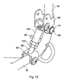
- Fig. 12 shows an arrangement to permit the inclination of the handle assembly 46 relative to the upper base frame 14 to be varied.
- the upwardly extending portion 38 is pivotally mounted about an axis 90 to the rear of the respective side members 34.
- a variable length connection member 92 extends between brackets 94, 96 provided respectively on the side member 34 and portion 38, with the length of the connection member 92 determining the inclination of the portion 38 and hence the elongate member 40 and therefore the handle assemblies.
- the connection members 92 include a threaded bar 98 on which a threaded sleeve 100 rotatingly engages, with a locking nut 102 for retaining the sleeve 100 in a required position on the bar 98.
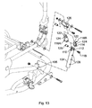
- Fig. 13 shows an arrangement permitting a desired inclination to be chosen between the lower and upper base frames 12, 14 when the first rigid form of the interconnection arrangement 50 is used.
- the arrangement 50 comprises a bar 104 telescopically mountable in a tube 106 of the lower base frame 12, with three through holes 108 to permit three different operative lengths of the cranked member 62 to be chosen.
- a slot 110 is provided between aligned holes 112.
- An eye 114 of a connecting member 116 is locatable in the slot 110 and mountable thereto by a bolt 118 and threaded sleeve 120.
- the connecting member 116 provides the upper part of the cranked member 62, and a reduced diameter portion 122 with a through hole 124 can be mounted to the upper base frame 14 by a bracket 126.
- Two different length connecting members 116 are provided as shown by A and B to provide different lengths of the cranked member 62 and hence relative inclinations between the lower and upper base frames 12, 14.
- Using the smaller connecting member 116B provides for a 5° rearward downward slope, and using the next hole 108 provides a 10° inclination, and the top most hole 108 a 15° inclination.
- Fig. 14 shows an arm rest assembly with an outwardly cranked square section member 128 which mounts a cross piece 130 to which a padded arm rest 132 can be mounted.
- the member 128 is telescopically mountable in a vertical sleeve 134 of a mounting bracket 136, which bracket 136 can be mounted to the front brackets 52 in a telescopic manner to provide lateral adjustment.
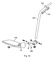
- Fig. 15 shows a first foot rest assembly.
- the assembly comprises respective cranked members 138 with an upper part which can extend into the front ends of the side members 34 and can be mounted thereto by brackets 140 engageable with corresponding brackets 142 provided on the front end of the side members 34, and can be held in place by sprung pins 144.
- Foot rests 146 are mounted on the lower end of the cranked members 138 by brackets 148.
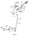
- Fig. 16 shows a second foot rest arrangement.
- cranked members 150 are provided with telescopic upper and lower parts 152, 154 to permit height adjustment of the foot rests 146.
- the cranked member 150 are pivotally mounted to mounting brackets 156 to permit the foot rests 146 to be pivoted out of the way when required.
- the mounting brackets 156 include cranked members 158 mountable to the brackets 142 and providing upper and lower pivotal mountings 160, 162 as well as a catch arrangement 164 for retaining the foot rests 146 in a use position.
- chassis frames may take a different form.
- a different arrangement could be provided to enable tilting of the respective frame parts.
- a different catch may be usable in the seat mounting arrangement.
- an arrangement with a hydraulic actuator could be used to vary the length of the first form of the interconnection arrangement.
- a different handle arrangement may be provided, and an arrangement which folds about a generally vertical central axis could be used.
Claims (7)
- Fahrgestell-Baugruppe (10) für einen Rollstuhl, wobei die Baugruppe (10) einen unteren Basisrahmen (12), an welchem mit dem Boden in Eingriff gelangende Räder (22, 26) montiert werden können, einen oberen Basisrahmen (14), an welchem eine Sitzanordnung montiert werden kann, und eine selektiv abnehmbare Verbindungsanordnung (50) zwischen dem unteren (12) und dem oberen (14) Basisrahmen enthält, wobei die Verbindungsanordnung in der einen oder anderen zweier Formen vorliegt, wobei die erste Form eine im wesentlichen starre Verbindung zwischen dem unteren (12) und dem oberen (14) Basisrahmen bewirkt, und die zweite Form ein selektives Kippen zwischen dem unteren (12) und dem oberen (14) Basisrahmen um eine Achse herum zur Vorderseite der Baugruppe hin gestattet, dadurch gekennzeichnet, dass die zweite Form der Verbindungsanordnung (50) ein Verbindungsglied (56) variabler Länge aufweist, wobei die Baugruppe einen ersten Montagepunkt (58) auf dem oberen Basisrahmen (14) zum hinteren Teil der Baugruppe hin für das Montieren eines ersten Endes der zweiten Form der Verbindungsanordnung, einen zweiten Montagepunkt (60) auf dem unteren Basisrahmen (12) für das Montieren eines zweiten Endes der zweiten Form der Verbindungsanordnung, einen dritten Montagepunkt (94) auf dem oberen Basisrahmen (14) zum hinteren Teil der Baugruppe hin für das Montieren eines ersten Endes der ersten Form der Verbindungsanordnung, und einen vierten Montagepunkt (106) auf dem unteren Basisrahmen (12) für das Montieren eines zweiten Endes der ersten Form der Verbindungsanordnung enthält.
- Baugruppe nach Anspruch 1, dadurch gekennzeichnet, dass die erste und die zweite Form der Verbindungsanordnung (50) ein vorderes Verbindungsglied (52) enthalten, welches zum vorderen Teil des Rollstuhls hin anordenbar ist und welches an dem unteren Basisrahmen (12) oder an dem oberen Basisrahmen (14) im wesentlichen starr montiert ist, und welches an dem anderen des oberen Basisrahmens (14) oder des unteren Basisrahmens (12) schwenkbar montiert ist.
- Baugruppe nach Anspruch 2, dadurch gekennzeichnet, dass das vordere Verbindungsglied (52) an dem unteren Basisrahmen (12) schwenkbar montiert ist.
- Baugruppe nach einem der vorhergehenden Ansprüche, dadurch gekennzeichnet, dass die erste Form der Verbindungsanordnung (50) ein im wesentliches starres hinteres Verbindungsglied (62) enthält, welches an dem unteren Basisrahmen (12) und dem oberen Basisrahmen (14) selektiv montierbar ist, um sich dazwischen zu dem hinteren Teil des Rollstuhls zu erstrecken.
- Baugruppe nach Anspruch 4, dadurch gekennzeichnet, dass eine Vielzahl auswählbarer Montagepositionen (108) für das hintere Verbindungsglied vorgesehen sind, um eine ausgewählte Neigung einer Vielzahl unterschiedlicher Neigungen zwischen dem unteren Basisrahmen (12) und dem oberen Basisrahmen (14) wählen zu können.
- Baugruppe nach einem der vorhergehenden Ansprüche, dadurch gekennzeichnet, dass das Verbindungsglied (56) variabler Länge in Form eines Kolbens und Zylinders vorliegt.
- Baugruppe nach Anspruch 6, dadurch gekennzeichnet, dass Mittel vorgesehen sind zum selektiven Verriegeln des Verbindungsglieds (56) variabler Länge bei einer erforderlichen Länge.
Priority Applications (1)
| Application Number | Priority Date | Filing Date | Title |
|---|---|---|---|
| EP10011572A EP2263630A1 (de) | 2005-05-14 | 2006-05-11 | Rollstühle |
Applications Claiming Priority (1)
| Application Number | Priority Date | Filing Date | Title |
|---|---|---|---|
| GBGB0509917.1A GB0509917D0 (en) | 2005-05-14 | 2005-05-14 | Wheelchairs |
Related Child Applications (1)
| Application Number | Title | Priority Date | Filing Date |
|---|---|---|---|
| EP10011572.4 Division-Into | 2010-09-29 |
Publications (3)
| Publication Number | Publication Date |
|---|---|
| EP1721592A2 EP1721592A2 (de) | 2006-11-15 |
| EP1721592A3 EP1721592A3 (de) | 2006-11-22 |
| EP1721592B1 true EP1721592B1 (de) | 2013-08-07 |
Family
ID=34708208
Family Applications (2)
| Application Number | Title | Priority Date | Filing Date |
|---|---|---|---|
| EP06252484.8A Not-in-force EP1721592B1 (de) | 2005-05-14 | 2006-05-11 | Rollstühle |
| EP10011572A Withdrawn EP2263630A1 (de) | 2005-05-14 | 2006-05-11 | Rollstühle |
Family Applications After (1)
| Application Number | Title | Priority Date | Filing Date |
|---|---|---|---|
| EP10011572A Withdrawn EP2263630A1 (de) | 2005-05-14 | 2006-05-11 | Rollstühle |
Country Status (2)
| Country | Link |
|---|---|
| EP (2) | EP1721592B1 (de) |
| GB (1) | GB0509917D0 (de) |
Families Citing this family (2)
| Publication number | Priority date | Publication date | Assignee | Title |
|---|---|---|---|---|
| US20110018222A1 (en) | 2007-12-21 | 2011-01-27 | Michael Knopf | Caster Strut, Wheelchair Frame and Wheelchair |
| ATE496605T1 (de) | 2008-10-10 | 2011-02-15 | Sunrise Medical Gmbh & Co Kg | ROLLSTUHL MIT FUßSTÜTZE |
Family Cites Families (7)
| Publication number | Priority date | Publication date | Assignee | Title |
|---|---|---|---|---|
| US4555121A (en) * | 1984-09-20 | 1985-11-26 | Invacare Corporation | Invalid's chair to facilitate transfer to an automobile |
| DE19525719B4 (de) * | 1994-07-14 | 2004-08-26 | Everest & Jennings International Ltd. | Rollstuhl und Rollstuhlrahmen mit Aufhängung |
| US5718442A (en) * | 1995-12-27 | 1998-02-17 | Mechanical Application Designs, Inc. | Power wheelchair with extended power seat frame tilt |
| AU1360099A (en) * | 1997-10-06 | 1999-04-27 | Pride Health Care, Inc. | Foldable power wheelchair |
| CH689177A5 (de) * | 1997-12-23 | 1998-11-30 | Kueschall Design Ag | Rollstuhl mit geschlossenem dreidimensionalem Rahmen. |
| US20030006578A1 (en) * | 1998-10-01 | 2003-01-09 | Freedom Designs Incorporated | Size-adjustable laterally-folding tilting-frame wheelchair |
| US7207403B2 (en) * | 2003-10-08 | 2007-04-24 | Pride Mobility Products Corporation | Transportable power wheelchair |
-
2005
- 2005-05-14 GB GBGB0509917.1A patent/GB0509917D0/en not_active Ceased
-
2006
- 2006-05-11 EP EP06252484.8A patent/EP1721592B1/de not_active Not-in-force
- 2006-05-11 EP EP10011572A patent/EP2263630A1/de not_active Withdrawn
Also Published As
| Publication number | Publication date |
|---|---|
| EP2263630A1 (de) | 2010-12-22 |
| GB0509917D0 (en) | 2005-06-22 |
| EP1721592A3 (de) | 2006-11-22 |
| EP1721592A2 (de) | 2006-11-15 |
Similar Documents
| Publication | Publication Date | Title |
|---|---|---|
| CA2198643C (en) | Wheelchair for large individuals | |
| EP2007337B1 (de) | Rollstuhl | |
| CA2601470C (en) | A height adjustable wheelchair | |
| US20030006578A1 (en) | Size-adjustable laterally-folding tilting-frame wheelchair | |
| US20070085301A1 (en) | Center-of-gravity tilt-in-space wheelchair | |
| CA2941579C (en) | Stand-up wheelchair | |
| AU2001281097B2 (en) | A wheelchair seat having adjustable telescoping assembly | |
| AU2001281097A1 (en) | A wheelchair seat having adjustable telescoping assembly | |
| EP1721592B1 (de) | Rollstühle | |
| US7222921B2 (en) | Wheelchair with foot rest | |
| WO2009080347A2 (en) | Wheelchair frame and wheelchair with cross-brace | |
| AU2003213829A1 (en) | Adjustable seating system | |
| AU2007231838A1 (en) | Improved Rollator | |
| US7134678B2 (en) | Wheelchair | |
| US8919808B2 (en) | Stroller, especially rehab stroller | |
| US20060131833A1 (en) | Wheelchairs | |
| EP0945114A1 (de) | Kippbarer Rollstuhl mit Tragfederelement | |
| JPH0337063A (ja) | 車椅子用リクライニング背もたれ組立体 | |
| CA2594566A1 (en) | Light weight foldable and customizable wheelchair | |
| US20050151407A1 (en) | Beach chair | |
| JP4662761B2 (ja) | 車椅子用の折り畳み式転倒防止装置 | |
| FR3005852A1 (fr) | Fauteuil roulant pour handicape ou invalide a assiette de chassis reglable | |
| NZ328792A (en) | Foldable chair with back rest of variable inclination | |
| AU2013221981A1 (en) | Wheelchair | |
| NO790876L (no) | Sammenleggbar rullestol. |
Legal Events
| Date | Code | Title | Description |
|---|---|---|---|
| PUAI | Public reference made under article 153(3) epc to a published international application that has entered the european phase |
Free format text: ORIGINAL CODE: 0009012 |
|
| PUAL | Search report despatched |
Free format text: ORIGINAL CODE: 0009013 |
|
| AK | Designated contracting states |
Kind code of ref document: A2 Designated state(s): AT BE BG CH CY CZ DE DK EE ES FI FR GB GR HU IE IS IT LI LT LU LV MC NL PL PT RO SE SI SK TR |
|
| AX | Request for extension of the european patent |
Extension state: AL BA HR MK YU |
|
| AK | Designated contracting states |
Kind code of ref document: A3 Designated state(s): AT BE BG CH CY CZ DE DK EE ES FI FR GB GR HU IE IS IT LI LT LU LV MC NL PL PT RO SE SI SK TR |
|
| AX | Request for extension of the european patent |
Extension state: AL BA HR MK YU |
|
| 17P | Request for examination filed |
Effective date: 20070313 |
|
| 17Q | First examination report despatched |
Effective date: 20070416 |
|
| AKX | Designation fees paid |
Designated state(s): AT BE BG CH CY CZ DE DK EE ES FI FR GB GR HU IE IS IT LI LT LU LV MC NL PL PT RO SE SI SK TR |
|
| GRAP | Despatch of communication of intention to grant a patent |
Free format text: ORIGINAL CODE: EPIDOSNIGR1 |
|
| GRAS | Grant fee paid |
Free format text: ORIGINAL CODE: EPIDOSNIGR3 |
|
| GRAA | (expected) grant |
Free format text: ORIGINAL CODE: 0009210 |
|
| AK | Designated contracting states |
Kind code of ref document: B1 Designated state(s): AT BE BG CH CY CZ DE DK EE ES FI FR GB GR HU IE IS IT LI LT LU LV MC NL PL PT RO SE SI SK TR |
|
| REG | Reference to a national code |
Ref country code: GB Ref legal event code: FG4D |
|
| REG | Reference to a national code |
Ref country code: CH Ref legal event code: EP Ref country code: AT Ref legal event code: REF Ref document number: 625403 Country of ref document: AT Kind code of ref document: T Effective date: 20130815 |
|
| REG | Reference to a national code |
Ref country code: IE Ref legal event code: FG4D |
|
| RIN2 | Information on inventor provided after grant (corrected) |
Inventor name: MCQUILTON, GORDON C/OSPECIALISED ORTHOTIC SERV.LTD |
|
| REG | Reference to a national code |
Ref country code: DE Ref legal event code: R096 Ref document number: 602006037708 Country of ref document: DE Effective date: 20131002 |
|
| RAP2 | Party data changed (patent owner data changed or rights of a patent transferred) |
Owner name: SPECIALISED ORTHOTIC SERVICES LIMITED |
|
| REG | Reference to a national code |
Ref country code: AT Ref legal event code: MK05 Ref document number: 625403 Country of ref document: AT Kind code of ref document: T Effective date: 20130807 |
|
| REG | Reference to a national code |
Ref country code: NL Ref legal event code: VDEP Effective date: 20130807 |
|
| REG | Reference to a national code |
Ref country code: LT Ref legal event code: MG4D |
|
| PG25 | Lapsed in a contracting state [announced via postgrant information from national office to epo] |
Ref country code: SE Free format text: LAPSE BECAUSE OF FAILURE TO SUBMIT A TRANSLATION OF THE DESCRIPTION OR TO PAY THE FEE WITHIN THE PRESCRIBED TIME-LIMIT Effective date: 20130807 Ref country code: CY Free format text: LAPSE BECAUSE OF FAILURE TO SUBMIT A TRANSLATION OF THE DESCRIPTION OR TO PAY THE FEE WITHIN THE PRESCRIBED TIME-LIMIT Effective date: 20130710 Ref country code: IS Free format text: LAPSE BECAUSE OF FAILURE TO SUBMIT A TRANSLATION OF THE DESCRIPTION OR TO PAY THE FEE WITHIN THE PRESCRIBED TIME-LIMIT Effective date: 20131207 Ref country code: AT Free format text: LAPSE BECAUSE OF FAILURE TO SUBMIT A TRANSLATION OF THE DESCRIPTION OR TO PAY THE FEE WITHIN THE PRESCRIBED TIME-LIMIT Effective date: 20130807 Ref country code: LT Free format text: LAPSE BECAUSE OF FAILURE TO SUBMIT A TRANSLATION OF THE DESCRIPTION OR TO PAY THE FEE WITHIN THE PRESCRIBED TIME-LIMIT Effective date: 20130807 Ref country code: PT Free format text: LAPSE BECAUSE OF FAILURE TO SUBMIT A TRANSLATION OF THE DESCRIPTION OR TO PAY THE FEE WITHIN THE PRESCRIBED TIME-LIMIT Effective date: 20131209 |
|
| PG25 | Lapsed in a contracting state [announced via postgrant information from national office to epo] |
Ref country code: SI Free format text: LAPSE BECAUSE OF FAILURE TO SUBMIT A TRANSLATION OF THE DESCRIPTION OR TO PAY THE FEE WITHIN THE PRESCRIBED TIME-LIMIT Effective date: 20130807 Ref country code: NL Free format text: LAPSE BECAUSE OF FAILURE TO SUBMIT A TRANSLATION OF THE DESCRIPTION OR TO PAY THE FEE WITHIN THE PRESCRIBED TIME-LIMIT Effective date: 20130807 Ref country code: LV Free format text: LAPSE BECAUSE OF FAILURE TO SUBMIT A TRANSLATION OF THE DESCRIPTION OR TO PAY THE FEE WITHIN THE PRESCRIBED TIME-LIMIT Effective date: 20130807 Ref country code: BE Free format text: LAPSE BECAUSE OF FAILURE TO SUBMIT A TRANSLATION OF THE DESCRIPTION OR TO PAY THE FEE WITHIN THE PRESCRIBED TIME-LIMIT Effective date: 20130807 Ref country code: FI Free format text: LAPSE BECAUSE OF FAILURE TO SUBMIT A TRANSLATION OF THE DESCRIPTION OR TO PAY THE FEE WITHIN THE PRESCRIBED TIME-LIMIT Effective date: 20130807 Ref country code: GR Free format text: LAPSE BECAUSE OF FAILURE TO SUBMIT A TRANSLATION OF THE DESCRIPTION OR TO PAY THE FEE WITHIN THE PRESCRIBED TIME-LIMIT Effective date: 20131108 Ref country code: PL Free format text: LAPSE BECAUSE OF FAILURE TO SUBMIT A TRANSLATION OF THE DESCRIPTION OR TO PAY THE FEE WITHIN THE PRESCRIBED TIME-LIMIT Effective date: 20130807 Ref country code: ES Free format text: LAPSE BECAUSE OF FAILURE TO SUBMIT A TRANSLATION OF THE DESCRIPTION OR TO PAY THE FEE WITHIN THE PRESCRIBED TIME-LIMIT Effective date: 20130807 |
|
| PG25 | Lapsed in a contracting state [announced via postgrant information from national office to epo] |
Ref country code: CY Free format text: LAPSE BECAUSE OF FAILURE TO SUBMIT A TRANSLATION OF THE DESCRIPTION OR TO PAY THE FEE WITHIN THE PRESCRIBED TIME-LIMIT Effective date: 20130807 |
|
| PG25 | Lapsed in a contracting state [announced via postgrant information from national office to epo] |
Ref country code: DK Free format text: LAPSE BECAUSE OF FAILURE TO SUBMIT A TRANSLATION OF THE DESCRIPTION OR TO PAY THE FEE WITHIN THE PRESCRIBED TIME-LIMIT Effective date: 20130807 Ref country code: SK Free format text: LAPSE BECAUSE OF FAILURE TO SUBMIT A TRANSLATION OF THE DESCRIPTION OR TO PAY THE FEE WITHIN THE PRESCRIBED TIME-LIMIT Effective date: 20130807 Ref country code: EE Free format text: LAPSE BECAUSE OF FAILURE TO SUBMIT A TRANSLATION OF THE DESCRIPTION OR TO PAY THE FEE WITHIN THE PRESCRIBED TIME-LIMIT Effective date: 20130807 Ref country code: CZ Free format text: LAPSE BECAUSE OF FAILURE TO SUBMIT A TRANSLATION OF THE DESCRIPTION OR TO PAY THE FEE WITHIN THE PRESCRIBED TIME-LIMIT Effective date: 20130807 Ref country code: RO Free format text: LAPSE BECAUSE OF FAILURE TO SUBMIT A TRANSLATION OF THE DESCRIPTION OR TO PAY THE FEE WITHIN THE PRESCRIBED TIME-LIMIT Effective date: 20130807 |
|
| PG25 | Lapsed in a contracting state [announced via postgrant information from national office to epo] |
Ref country code: IT Free format text: LAPSE BECAUSE OF FAILURE TO SUBMIT A TRANSLATION OF THE DESCRIPTION OR TO PAY THE FEE WITHIN THE PRESCRIBED TIME-LIMIT Effective date: 20130807 |
|
| PLBE | No opposition filed within time limit |
Free format text: ORIGINAL CODE: 0009261 |
|
| STAA | Information on the status of an ep patent application or granted ep patent |
Free format text: STATUS: NO OPPOSITION FILED WITHIN TIME LIMIT |
|
| 26N | No opposition filed |
Effective date: 20140508 |
|
| REG | Reference to a national code |
Ref country code: DE Ref legal event code: R097 Ref document number: 602006037708 Country of ref document: DE Effective date: 20140508 |
|
| PG25 | Lapsed in a contracting state [announced via postgrant information from national office to epo] |
Ref country code: LU Free format text: LAPSE BECAUSE OF FAILURE TO SUBMIT A TRANSLATION OF THE DESCRIPTION OR TO PAY THE FEE WITHIN THE PRESCRIBED TIME-LIMIT Effective date: 20140511 |
|
| REG | Reference to a national code |
Ref country code: CH Ref legal event code: PL |
|
| PG25 | Lapsed in a contracting state [announced via postgrant information from national office to epo] |
Ref country code: CH Free format text: LAPSE BECAUSE OF NON-PAYMENT OF DUE FEES Effective date: 20140531 Ref country code: LI Free format text: LAPSE BECAUSE OF NON-PAYMENT OF DUE FEES Effective date: 20140531 Ref country code: MC Free format text: LAPSE BECAUSE OF FAILURE TO SUBMIT A TRANSLATION OF THE DESCRIPTION OR TO PAY THE FEE WITHIN THE PRESCRIBED TIME-LIMIT Effective date: 20130807 |
|
| REG | Reference to a national code |
Ref country code: IE Ref legal event code: MM4A |
|
| PG25 | Lapsed in a contracting state [announced via postgrant information from national office to epo] |
Ref country code: IE Free format text: LAPSE BECAUSE OF NON-PAYMENT OF DUE FEES Effective date: 20140511 |
|
| REG | Reference to a national code |
Ref country code: FR Ref legal event code: PLFP Year of fee payment: 11 |
|
| PG25 | Lapsed in a contracting state [announced via postgrant information from national office to epo] |
Ref country code: BG Free format text: LAPSE BECAUSE OF FAILURE TO SUBMIT A TRANSLATION OF THE DESCRIPTION OR TO PAY THE FEE WITHIN THE PRESCRIBED TIME-LIMIT Effective date: 20130807 |
|
| PG25 | Lapsed in a contracting state [announced via postgrant information from national office to epo] |
Ref country code: HU Free format text: LAPSE BECAUSE OF FAILURE TO SUBMIT A TRANSLATION OF THE DESCRIPTION OR TO PAY THE FEE WITHIN THE PRESCRIBED TIME-LIMIT; INVALID AB INITIO Effective date: 20060511 Ref country code: TR Free format text: LAPSE BECAUSE OF FAILURE TO SUBMIT A TRANSLATION OF THE DESCRIPTION OR TO PAY THE FEE WITHIN THE PRESCRIBED TIME-LIMIT Effective date: 20130807 |
|
| REG | Reference to a national code |
Ref country code: FR Ref legal event code: PLFP Year of fee payment: 12 |
|
| REG | Reference to a national code |
Ref country code: FR Ref legal event code: PLFP Year of fee payment: 13 |
|
| PGFP | Annual fee paid to national office [announced via postgrant information from national office to epo] |
Ref country code: DE Payment date: 20180502 Year of fee payment: 13 |
|
| PGFP | Annual fee paid to national office [announced via postgrant information from national office to epo] |
Ref country code: FR Payment date: 20180425 Year of fee payment: 13 |
|
| PGFP | Annual fee paid to national office [announced via postgrant information from national office to epo] |
Ref country code: GB Payment date: 20180420 Year of fee payment: 13 |
|
| REG | Reference to a national code |
Ref country code: DE Ref legal event code: R119 Ref document number: 602006037708 Country of ref document: DE |
|
| GBPC | Gb: european patent ceased through non-payment of renewal fee |
Effective date: 20190511 |
|
| PG25 | Lapsed in a contracting state [announced via postgrant information from national office to epo] |
Ref country code: DE Free format text: LAPSE BECAUSE OF NON-PAYMENT OF DUE FEES Effective date: 20191203 Ref country code: GB Free format text: LAPSE BECAUSE OF NON-PAYMENT OF DUE FEES Effective date: 20190511 |
|
| PG25 | Lapsed in a contracting state [announced via postgrant information from national office to epo] |
Ref country code: FR Free format text: LAPSE BECAUSE OF NON-PAYMENT OF DUE FEES Effective date: 20190531 |