EP1721592B1 - Wheelchairs - Google Patents
Wheelchairs Download PDFInfo
- Publication number
- EP1721592B1 EP1721592B1 EP06252484.8A EP06252484A EP1721592B1 EP 1721592 B1 EP1721592 B1 EP 1721592B1 EP 06252484 A EP06252484 A EP 06252484A EP 1721592 B1 EP1721592 B1 EP 1721592B1
- Authority
- EP
- European Patent Office
- Prior art keywords
- mounting
- assembly
- base frame
- connecting member
- interconnection arrangement
- Prior art date
- Legal status (The legal status is an assumption and is not a legal conclusion. Google has not performed a legal analysis and makes no representation as to the accuracy of the status listed.)
- Not-in-force
Links
Images


Classifications
-
- A—HUMAN NECESSITIES
- A61—MEDICAL OR VETERINARY SCIENCE; HYGIENE
- A61G—TRANSPORT, PERSONAL CONVEYANCES, OR ACCOMMODATION SPECIALLY ADAPTED FOR PATIENTS OR DISABLED PERSONS; OPERATING TABLES OR CHAIRS; CHAIRS FOR DENTISTRY; FUNERAL DEVICES
- A61G5/00—Chairs or personal conveyances specially adapted for patients or disabled persons, e.g. wheelchairs
- A61G5/10—Parts, details or accessories
- A61G5/1056—Arrangements for adjusting the seat
- A61G5/1059—Arrangements for adjusting the seat adjusting the height of the seat
-
- A—HUMAN NECESSITIES
- A61—MEDICAL OR VETERINARY SCIENCE; HYGIENE
- A61G—TRANSPORT, PERSONAL CONVEYANCES, OR ACCOMMODATION SPECIALLY ADAPTED FOR PATIENTS OR DISABLED PERSONS; OPERATING TABLES OR CHAIRS; CHAIRS FOR DENTISTRY; FUNERAL DEVICES
- A61G5/00—Chairs or personal conveyances specially adapted for patients or disabled persons, e.g. wheelchairs
- A61G5/10—Parts, details or accessories
- A61G5/1056—Arrangements for adjusting the seat
- A61G5/1067—Arrangements for adjusting the seat adjusting the backrest relative to the seat portion
-
- A—HUMAN NECESSITIES
- A61—MEDICAL OR VETERINARY SCIENCE; HYGIENE
- A61G—TRANSPORT, PERSONAL CONVEYANCES, OR ACCOMMODATION SPECIALLY ADAPTED FOR PATIENTS OR DISABLED PERSONS; OPERATING TABLES OR CHAIRS; CHAIRS FOR DENTISTRY; FUNERAL DEVICES
- A61G5/00—Chairs or personal conveyances specially adapted for patients or disabled persons, e.g. wheelchairs
- A61G5/10—Parts, details or accessories
- A61G5/1056—Arrangements for adjusting the seat
- A61G5/1075—Arrangements for adjusting the seat tilting the whole seat backwards
-
- A—HUMAN NECESSITIES
- A61—MEDICAL OR VETERINARY SCIENCE; HYGIENE
- A61G—TRANSPORT, PERSONAL CONVEYANCES, OR ACCOMMODATION SPECIALLY ADAPTED FOR PATIENTS OR DISABLED PERSONS; OPERATING TABLES OR CHAIRS; CHAIRS FOR DENTISTRY; FUNERAL DEVICES
- A61G5/00—Chairs or personal conveyances specially adapted for patients or disabled persons, e.g. wheelchairs
- A61G5/10—Parts, details or accessories
- A61G5/1081—Parts, details or accessories with shock absorbers or other suspension arrangements between frame and seat
-
- A—HUMAN NECESSITIES
- A61—MEDICAL OR VETERINARY SCIENCE; HYGIENE
- A61G—TRANSPORT, PERSONAL CONVEYANCES, OR ACCOMMODATION SPECIALLY ADAPTED FOR PATIENTS OR DISABLED PERSONS; OPERATING TABLES OR CHAIRS; CHAIRS FOR DENTISTRY; FUNERAL DEVICES
- A61G5/00—Chairs or personal conveyances specially adapted for patients or disabled persons, e.g. wheelchairs
- A61G5/10—Parts, details or accessories
- A61G5/12—Rests specially adapted therefor, e.g. for the head or the feet
- A61G5/125—Rests specially adapted therefor, e.g. for the head or the feet for arms
-
- A—HUMAN NECESSITIES
- A61—MEDICAL OR VETERINARY SCIENCE; HYGIENE
- A61G—TRANSPORT, PERSONAL CONVEYANCES, OR ACCOMMODATION SPECIALLY ADAPTED FOR PATIENTS OR DISABLED PERSONS; OPERATING TABLES OR CHAIRS; CHAIRS FOR DENTISTRY; FUNERAL DEVICES
- A61G5/00—Chairs or personal conveyances specially adapted for patients or disabled persons, e.g. wheelchairs
- A61G5/10—Parts, details or accessories
- A61G5/12—Rests specially adapted therefor, e.g. for the head or the feet
- A61G5/128—Rests specially adapted therefor, e.g. for the head or the feet for feet
Definitions
- This invention concerns improvements in or relating to wheelchairs, and particularly but not exclusively wheelchair chassis.
- wheelchairs which are specifically designed or adapted to meet the particular requirements of a user. This may for instance mean having an appropriate seating arrangement for a particular person and/or their disability. In some cases it is appropriate, or at least desirable, to provide a tilt option on a wheelchair. However, to provide bespoke wheelchairs for each user would involve considerable costs, and this option is therefore not available for many people.
- the apparatus disclosed by US 5727802 includes an interconnection arrangement between the upper and lower base frames comprising a shock absorber. This document does not though show a wheelchair including first and second mounting points for mounting an interconnection permitting tilting, and third and fourth mounting points for mounting a rigid interconnection.
- a wheelchair chassis assembly including a lower base frame which can mount ground engaging wheels, an upper base frame which can mount a seat arrangement, and a selectively removable interconnection arrangement between the lower and upper base frames, the interconnection arrangement being in either one of two forms, the first form providing a substantially rigid connection between the lower and upper base frames, and the second form permitting selective tilting between the lower and upper base frames about an axis towards the front of the assembly, characterised in that the second form of the interconnection arrangement comprises a variable length connecting member, the assembly including a first mounting point on the upper base frame toward the rear of the assembly for mounting a first end of the second form of the interconnection arrangement, a second mounting point on the lower base frame for mounting a second end of the second form of the interconnection arrangement, a third mounting point on the upper base frame toward the rear of the assembly for mounting a first end of the first form of the interconnection arrangement, and a fourth mounting point on the lower base frame for mounting a second end of the first form of the interconnection arrangement
- the first and second forms of the interconnection arrangement may include a front connecting member locatable towards the front of the wheelchair and which is substantially rigidly mounted to a one of the lower or upper base frames, and which is pivotally mounted to the other of the lower or upper base frames.
- the front connecting member is preferably pivotally mounted to the lower base frame.
- the first form of the interconnection arrangement preferably includes a substantially rigid rear connecting member which is selectively mountable to the lower and upper base frames to extend therebetween, towards the rear of the wheelchair.
- a plurality of selectable mounting positions for the rear connecting member may be provided to permit a selected one of a plurality of different inclinations between the lower and upper base frames to be chosen.
- variable length connecting member may be in the form of a piston and cylinder, and may include a gas strut.
- a hydraulic actuator may be provided for changing the length of the variable length connecting member.
- Means may be provided for selectively locking the variable length connecting member at a required length.
- the drawings show a wheelchair chassis 10 suitable for mounting a wide variety of seat arrangements (not shown aside from a chassis member therefor).
- the chassis 10 comprises a lower base frame 12 and an upper base frame 14.
- the lower base frame 12 is made of tubular components with side frames 16 interconnected at the front by a cross member 18 in the form of two Y's joined by their stems, and interconnected at the rear by a cross member 20.
- Each side frame 16 mounts a front wheel 22 on a swivel 24, and a larger rear wheel 26.
- a brake 28 with an operating lever 30 is provided for each wheel 26.
- the upper base frame 14 includes a generally square lower part 32 with side members 34 joined by cross members 36.
- a handle assembly extends from the rear of the cross members 36 and comprises a first upwardly extending portion 38.
- a shaped elongate member 40 extends from the portion 38 on each side and is joined by a cross member 42.
- the members 40 are pivotally mounted to the portions 38 by joints 44. In use the members 40 extend from the portions 38 in a generally parallel configuration. The members 40 can be held in this configuration by clips 45. When the chassis 10 is not in use, the clips 45 can be released, and the members 40 pivotted forwards onto the part 32, for storage and transportation.
- Cranked handle members 46 telescopically locate in the upper ends of the elongate members 40, and the height of the handle members 46 can be adjusted as illustrated at 47 in Fig. 1 to a required height for a person pushing the wheelchair.
- a locking nut 48 is provided for retaining the handle members 46 at a required height.
- Grips 49 are provided on the end of the handle members 46.
- the arrangement 50 includes a pair of front brackets 52, one on each side of the chassis 10 towards the front thereof.
- the front brackets 52 comprise shaped strips which extend with a generally U-shaped cross section from a pivotal mounting 54 on the lower base frame 12 around a respective one of the side members 34.
- a pair of gas struts 56 are provided, one on each side of the chassis.
- Each strut 56 extends from a mounting 58 at the rear of the respective side member 34 to a mounting 60 on the respective side frame 16 in front of the respective rear wheel 26.
- Fig. 1 shows the chassis 10 in an upright condition with the gas struts 56 extended. If the gas struts 56 are retracted the upper base frame 14 will recline rearwardly as shown in Fig. 4 .
- a valve (not shown) on the struts 56 is connected to a control 61 mounted on a one of the handle members 46, such that the struts 56 can only be moved and hence the upper base frame 14 tilted, when the control 61 is squeezed towards the respective grip 49.
- Fig. 5 shows a first form of the interconnection arrangement 50 where rather than the gas strut 56 extending between the lower and upper base frames 12, 14 towards the rear thereof, a rigid gently cranked member 62 is provided, which maintains the chassis 10 in an upright condition as shown in Fig. 5 .
- the two forms of the interconnection arrangement 50 permit common parts to be used in both a reclining and rigid form of the chassis 10, thereby providing significant time and cost savings during manufacture.
- Figs. 6 - 11 illustrate a mounting arrangement 64 for selectively mounting a seat arrangement on the chassis 10.
- Figs. 6 and 7 show a one of the side members 34, with the front of the chassis 10 towards the right as shown in these drawings.
- a first receiving part in the form of a location lug 66 is provided towards the front of the side members 34.
- the lugs 66 define a recess 68 between the lug 66 and the side member 34.
- a second receiving part in the form of a catch 70 is provided on each side member 34 towards the rear thereof.
- the catch 70 includes a pivotally mounted plate 72 defining a recess 74 with an opening 76.
- the catch 70 is arranged such that in a first condition as shown in Fig. 7 , the opening 76 points generally upwards, but when a downwards force is applied thereto the plate 72 will pivot by virtue of a spring 78 mounted thereto to a position shown in Figs. 6 and 8 with the opening 76 facing at an inclination away from the vertical.
- Figs. 6 and 7 show a chassis member 80 provided on the underneath of a seat assembly which chassis with front and rear cross members 82, 84 extending. The remainder of the assembly is not shown,
- the front cross member 82 is first located in the recesses 68.
- the rear cross member 84 is then moved through the openings 76 into the recesses 74, which action will cause the plates 72 to rotate to the alignment shown in Figs. 6 and 8 to trap the rear cross member 84 in the recesses 74 and hence retain the seat chassis on the chassis 10.
- a contoured handle 86 extends between the catches 70 on each side of the chassis 10 and connects by links 88 to the plate 72, such that rearward movement of the handle 86 will cause the plate 72 to return to the alignment shown in Fig. 7 to permit release of the seat chassis.
- This seat mounting arrangement readily permits a seating arrangement to be located and automatically locked on the wheelchair chassis 10, but to be readily removed therefrom using the handle 86.
- Fig. 12 shows an arrangement to permit the inclination of the handle assembly 46 relative to the upper base frame 14 to be varied.
- the upwardly extending portion 38 is pivotally mounted about an axis 90 to the rear of the respective side members 34.
- a variable length connection member 92 extends between brackets 94, 96 provided respectively on the side member 34 and portion 38, with the length of the connection member 92 determining the inclination of the portion 38 and hence the elongate member 40 and therefore the handle assemblies.
- the connection members 92 include a threaded bar 98 on which a threaded sleeve 100 rotatingly engages, with a locking nut 102 for retaining the sleeve 100 in a required position on the bar 98.
- Fig. 13 shows an arrangement permitting a desired inclination to be chosen between the lower and upper base frames 12, 14 when the first rigid form of the interconnection arrangement 50 is used.
- the arrangement 50 comprises a bar 104 telescopically mountable in a tube 106 of the lower base frame 12, with three through holes 108 to permit three different operative lengths of the cranked member 62 to be chosen.
- a slot 110 is provided between aligned holes 112.
- An eye 114 of a connecting member 116 is locatable in the slot 110 and mountable thereto by a bolt 118 and threaded sleeve 120.
- the connecting member 116 provides the upper part of the cranked member 62, and a reduced diameter portion 122 with a through hole 124 can be mounted to the upper base frame 14 by a bracket 126.
- Two different length connecting members 116 are provided as shown by A and B to provide different lengths of the cranked member 62 and hence relative inclinations between the lower and upper base frames 12, 14.
- Using the smaller connecting member 116B provides for a 5° rearward downward slope, and using the next hole 108 provides a 10° inclination, and the top most hole 108 a 15° inclination.
- Fig. 14 shows an arm rest assembly with an outwardly cranked square section member 128 which mounts a cross piece 130 to which a padded arm rest 132 can be mounted.
- the member 128 is telescopically mountable in a vertical sleeve 134 of a mounting bracket 136, which bracket 136 can be mounted to the front brackets 52 in a telescopic manner to provide lateral adjustment.
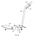
- Fig. 15 shows a first foot rest assembly.
- the assembly comprises respective cranked members 138 with an upper part which can extend into the front ends of the side members 34 and can be mounted thereto by brackets 140 engageable with corresponding brackets 142 provided on the front end of the side members 34, and can be held in place by sprung pins 144.
- Foot rests 146 are mounted on the lower end of the cranked members 138 by brackets 148.
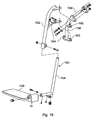
- Fig. 16 shows a second foot rest arrangement.
- cranked members 150 are provided with telescopic upper and lower parts 152, 154 to permit height adjustment of the foot rests 146.
- the cranked member 150 are pivotally mounted to mounting brackets 156 to permit the foot rests 146 to be pivoted out of the way when required.
- the mounting brackets 156 include cranked members 158 mountable to the brackets 142 and providing upper and lower pivotal mountings 160, 162 as well as a catch arrangement 164 for retaining the foot rests 146 in a use position.
- chassis frames may take a different form.
- a different arrangement could be provided to enable tilting of the respective frame parts.
- a different catch may be usable in the seat mounting arrangement.
- an arrangement with a hydraulic actuator could be used to vary the length of the first form of the interconnection arrangement.
- a different handle arrangement may be provided, and an arrangement which folds about a generally vertical central axis could be used.
Description
- This invention concerns improvements in or relating to wheelchairs, and particularly but not exclusively wheelchair chassis.
- With wheelchairs for the disabled, it is desirable to provide wheelchairs which are specifically designed or adapted to meet the particular requirements of a user. This may for instance mean having an appropriate seating arrangement for a particular person and/or their disability. In some cases it is appropriate, or at least desirable, to provide a tilt option on a wheelchair. However, to provide bespoke wheelchairs for each user would involve considerable costs, and this option is therefore not available for many people.
- The apparatus disclosed by
US 5727802 includes an interconnection arrangement between the upper and lower base frames comprising a shock absorber. This document does not though show a wheelchair including first and second mounting points for mounting an interconnection permitting tilting, and third and fourth mounting points for mounting a rigid interconnection. - According to one aspect of the present invention there is provided a wheelchair chassis assembly, the assembly including a lower base frame which can mount ground engaging wheels, an upper base frame which can mount a seat arrangement, and a selectively removable interconnection arrangement between the lower and upper base frames, the interconnection arrangement being in either one of two forms, the first form providing a substantially rigid connection between the lower and upper base frames, and the second form permitting selective tilting between the lower and upper base frames about an axis towards the front of the assembly, characterised in that the second form of the interconnection arrangement comprises a variable length connecting member, the assembly including a first mounting point on the upper base frame toward the rear of the assembly for mounting a first end of the second form of the interconnection arrangement, a second mounting point on the lower base frame for mounting a second end of the second form of the interconnection arrangement, a third mounting point on the upper base frame toward the rear of the assembly for mounting a first end of the first form of the interconnection arrangement, and a fourth mounting point on the lower base frame for mounting a second end of the first form of the interconnection arrangement.
- The first and second forms of the interconnection arrangement may include a front connecting member locatable towards the front of the wheelchair and which is substantially rigidly mounted to a one of the lower or upper base frames, and which is pivotally mounted to the other of the lower or upper base frames. The front connecting member is preferably pivotally mounted to the lower base frame.
- The first form of the interconnection arrangement preferably includes a substantially rigid rear connecting member which is selectively mountable to the lower and upper base frames to extend therebetween, towards the rear of the wheelchair.
- A plurality of selectable mounting positions for the rear connecting member may be provided to permit a selected one of a plurality of different inclinations between the lower and upper base frames to be chosen.
- The variable length connecting member may be in the form of a piston and cylinder, and may include a gas strut.
- Alternatively a hydraulic actuator may be provided for changing the length of the variable length connecting member. Means may be provided for selectively locking the variable length connecting member at a required length.
- Embodiments of the present invention will now be described by way of example only and with reference to the accompanying drawings, in which:-
-
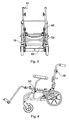
Fig. 1 is a diagrammatic side view of part of a wheelchair according to the invention in an upright condition, and incorporating a second form of interconnection arrangement; -
Fig. 2 is a diagrammatic perspective view of the part of a wheelchair ofFig. 1 ; -
Fig. 3 is a diagrammatic front view of the part of a wheelchair ofFig. 1 ; -
Fig. 4 is a diagrammatic side view of the part of a wheelchair ofFig. 1 in a tilted condition; -
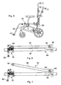
Fig. 5 is a diagrammatic side view of the part of a wheelchair ofFig. 1 but with a first form of interconnection arrangement; -
Fig. 6 is a diagrammatic side view of part of the part of a wheelchair ofFig. 1 in a first condition; -
Fig. 7 is a similar view toFig. 6 but in a second condition; -
Fig. 8 is a diagrammatic more detailed side view of part of the wheelchair chassis shown inFigs. 6 and 7 ; -
Figs. 9, 10 and 11 are respectively sectional views along the lines A-A, B-B, and C-C ofFig. 8 ; -
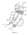
Fig. 12 is an exploded perspective view of part of the wheelchair ofFig. 1 ; -
Fig. 13 is a diagrammatic perspective exploded view of part of the wheelchair ofFig. 5 ; -
Fig. 14 is a diagrammatic exploded view of an arm rest arrangement as shown inFig. 1 ; and -
Figs. 15 and16 are diagrammatic perspective exploded views of first and second foot rest assemblies. - The drawings show a
wheelchair chassis 10 suitable for mounting a wide variety of seat arrangements (not shown aside from a chassis member therefor). Thechassis 10 comprises alower base frame 12 and anupper base frame 14. Thelower base frame 12 is made of tubular components withside frames 16 interconnected at the front by across member 18 in the form of two Y's joined by their stems, and interconnected at the rear by across member 20. Eachside frame 16 mounts afront wheel 22 on a swivel 24, and a largerrear wheel 26. Abrake 28 with anoperating lever 30 is provided for eachwheel 26. - The
upper base frame 14 includes a generally squarelower part 32 withside members 34 joined bycross members 36. A handle assembly extends from the rear of thecross members 36 and comprises a first upwardly extendingportion 38. A shapedelongate member 40 extends from theportion 38 on each side and is joined by across member 42. Themembers 40 are pivotally mounted to theportions 38 byjoints 44. In use themembers 40 extend from theportions 38 in a generally parallel configuration. Themembers 40 can be held in this configuration byclips 45. When thechassis 10 is not in use, theclips 45 can be released, and themembers 40 pivotted forwards onto thepart 32, for storage and transportation. - Cranked
handle members 46 telescopically locate in the upper ends of theelongate members 40, and the height of thehandle members 46 can be adjusted as illustrated at 47 inFig. 1 to a required height for a person pushing the wheelchair. Alocking nut 48 is provided for retaining thehandle members 46 at a required height.Grips 49 are provided on the end of thehandle members 46. - An
interconnection arrangement 50 is provided between the lower andupper base frames arrangement 50 includes a pair offront brackets 52, one on each side of thechassis 10 towards the front thereof. Thefront brackets 52 comprise shaped strips which extend with a generally U-shaped cross section from apivotal mounting 54 on thelower base frame 12 around a respective one of theside members 34. - In a second form of the interconnection arrangement 50 a pair of
gas struts 56 are provided, one on each side of the chassis. Eachstrut 56 extends from amounting 58 at the rear of therespective side member 34 to amounting 60 on therespective side frame 16 in front of the respectiverear wheel 26.Fig. 1 shows thechassis 10 in an upright condition with thegas struts 56 extended. If thegas struts 56 are retracted theupper base frame 14 will recline rearwardly as shown inFig. 4 . - A valve (not shown) on the
struts 56 is connected to acontrol 61 mounted on a one of thehandle members 46, such that thestruts 56 can only be moved and hence theupper base frame 14 tilted, when thecontrol 61 is squeezed towards therespective grip 49. -
Fig. 5 shows a first form of theinterconnection arrangement 50 where rather than thegas strut 56 extending between the lower andupper base frames member 62 is provided, which maintains thechassis 10 in an upright condition as shown inFig. 5 . - The two forms of the
interconnection arrangement 50 permit common parts to be used in both a reclining and rigid form of thechassis 10, thereby providing significant time and cost savings during manufacture. -
Figs. 6 - 11 illustrate amounting arrangement 64 for selectively mounting a seat arrangement on thechassis 10.Figs. 6 and 7 show a one of theside members 34, with the front of thechassis 10 towards the right as shown in these drawings. A first receiving part in the form of alocation lug 66 is provided towards the front of theside members 34. Thelugs 66 define arecess 68 between thelug 66 and theside member 34. - A second receiving part in the form of a
catch 70 is provided on eachside member 34 towards the rear thereof. Thecatch 70 includes a pivotally mountedplate 72 defining a recess 74 with an opening 76. Thecatch 70 is arranged such that in a first condition as shown inFig. 7 , the opening 76 points generally upwards, but when a downwards force is applied thereto theplate 72 will pivot by virtue of aspring 78 mounted thereto to a position shown inFigs. 6 and8 with the opening 76 facing at an inclination away from the vertical. -
Figs. 6 and 7 show achassis member 80 provided on the underneath of a seat assembly which chassis with front andrear cross members wheelchair chassis 10, thefront cross member 82 is first located in therecesses 68. Therear cross member 84 is then moved through theopenings 76 into the recesses 74, which action will cause theplates 72 to rotate to the alignment shown inFigs. 6 and8 to trap therear cross member 84 in the recesses 74 and hence retain the seat chassis on thechassis 10. - A
contoured handle 86 extends between thecatches 70 on each side of thechassis 10 and connects bylinks 88 to theplate 72, such that rearward movement of thehandle 86 will cause theplate 72 to return to the alignment shown inFig. 7 to permit release of the seat chassis. - This seat mounting arrangement readily permits a seating arrangement to be located and automatically locked on the
wheelchair chassis 10, but to be readily removed therefrom using thehandle 86. -
Fig. 12 shows an arrangement to permit the inclination of thehandle assembly 46 relative to theupper base frame 14 to be varied. Here the upwardly extendingportion 38 is pivotally mounted about anaxis 90 to the rear of therespective side members 34. A variablelength connection member 92 extends betweenbrackets side member 34 andportion 38, with the length of theconnection member 92 determining the inclination of theportion 38 and hence theelongate member 40 and therefore the handle assemblies. Theconnection members 92 include a threadedbar 98 on which a threadedsleeve 100 rotatingly engages, with a lockingnut 102 for retaining thesleeve 100 in a required position on thebar 98. -
Fig. 13 shows an arrangement permitting a desired inclination to be chosen between the lower and upper base frames 12, 14 when the first rigid form of theinterconnection arrangement 50 is used. Here thearrangement 50 comprises abar 104 telescopically mountable in atube 106 of thelower base frame 12, with three throughholes 108 to permit three different operative lengths of the crankedmember 62 to be chosen. - At the upper end of the bar 104 a
slot 110 is provided between alignedholes 112. Aneye 114 of a connecting member 116 is locatable in theslot 110 and mountable thereto by abolt 118 and threadedsleeve 120. The connecting member 116 provides the upper part of the crankedmember 62, and a reduceddiameter portion 122 with a throughhole 124 can be mounted to theupper base frame 14 by abracket 126. - Two different length connecting members 116 are provided as shown by A and B to provide different lengths of the cranked
member 62 and hence relative inclinations between the lower and upper base frames 12, 14. Using the longer connectingmember 116A and the lowermost throughholes 108, provides for a substantially horizontalupper base frame 14. Using the smaller connectingmember 116B provides for a 5° rearward downward slope, and using thenext hole 108 provides a 10° inclination, and the top most hole 108 a 15° inclination. -
Fig. 14 shows an arm rest assembly with an outwardly crankedsquare section member 128 which mounts across piece 130 to which a paddedarm rest 132 can be mounted. Themember 128 is telescopically mountable in avertical sleeve 134 of a mountingbracket 136, whichbracket 136 can be mounted to thefront brackets 52 in a telescopic manner to provide lateral adjustment. -
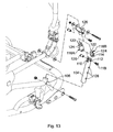
Fig. 15 shows a first foot rest assembly. The assembly comprises respective crankedmembers 138 with an upper part which can extend into the front ends of theside members 34 and can be mounted thereto bybrackets 140 engageable withcorresponding brackets 142 provided on the front end of theside members 34, and can be held in place by sprungpins 144. Foot rests 146 are mounted on the lower end of the crankedmembers 138 bybrackets 148. -
Fig. 16 shows a second foot rest arrangement. Here crankedmembers 150 are provided with telescopic upper andlower parts member 150 are pivotally mounted to mountingbrackets 156 to permit the foot rests 146 to be pivoted out of the way when required. The mountingbrackets 156 include crankedmembers 158 mountable to thebrackets 142 and providing upper and lowerpivotal mountings catch arrangement 164 for retaining the foot rests 146 in a use position. - It is to be realised that various other modifications may be made without departing from the scope of the invention. For instance it may be required to only provide one of either the base frame interconnection arrangements or the seat mounting arrangements. The chassis frames may take a different form. A different arrangement could be provided to enable tilting of the respective frame parts. A different catch may be usable in the seat mounting arrangement.
- Rather than the gas struts described, an arrangement with a hydraulic actuator could be used to vary the length of the first form of the interconnection arrangement.
- A different handle arrangement may be provided, and an arrangement which folds about a generally vertical central axis could be used.
Claims (7)
- A wheelchair chassis assembly (10), the assembly (10) including a lower base frame (12) which can mount ground engaging wheels (22, 26), an upper base frame (14) which can mount a seat arrangement, and a selectively removable interconnection arrangement (50) between the lower (12) and upper (14) base frames, the interconnection arrangement (50) being in either one of two forms, the first form providing a substantially rigid connection between the lower (12) and upper (14) base frames, and the second form permitting selective tilting between the lower (12) and upper (14) base frames about an axis towards the front of the assembly, characterised in that the second form of the interconnection arrangement comprises a variable length connecting member (56), the assembly including a first mounting point (58) on the upper base frame (14) toward the rear of the assembly for mounting a first end of the second form of the interconnection arrangement, a second mounting point (60) on the lower base frame (12) for mounting a second end of the second form of the interconnection arrangement, a third mounting point (94) on the upper base frame (14) toward the rear of the assembly for mounting a first end of the first form of the interconnection arrangement, and a fourth mounting point (106) on the lower base frame (12) for mounting a second end of the first form of the interconnection arrangement.
- An assembly according to claim 1, characterised in that the first and second forms of the interconnection arrangement (50) include a front connecting member (52) locatable towards the front of the wheelchair and which is substantially rigidly mounted to a one of the lower (12) or upper (14) base frames, and which is pivotally mounted to the other of the lower (12) or upper (14) base frames.
- An assembly according to claim 2, characterised in that the front connecting member (52) is pivotally mounted to the lower base frame (12).
- An assembly according to any of the preceding claims, characterised in that the first form of the interconnection arrangement (50) includes a substantially rigid rear connecting member (62) which is selectively mountable to the lower (12) and upper (14) base frames to extend therebetween, towards the rear of the wheelchair.
- An assembly according to claim 4, characterised in that a plurality of selectable mounting positions (108) for the rear connecting member are provided to permit a selected one of a plurality of different inclinations between the lower (12) and upper (14) base frames to be chosen.
- An assembly according to any of the preceding claims, characterised in that the variable length connecting member (56) is in the form of a piston and cylinder.
- An assembly according to claim 6, characterised in that means are provided for selectively locking the variable length connecting member (56) at a required length.
Priority Applications (1)
| Application Number | Priority Date | Filing Date | Title |
|---|---|---|---|
| EP10011572A EP2263630A1 (en) | 2005-05-14 | 2006-05-11 | Wheelchairs |
Applications Claiming Priority (1)
| Application Number | Priority Date | Filing Date | Title |
|---|---|---|---|
| GBGB0509917.1A GB0509917D0 (en) | 2005-05-14 | 2005-05-14 | Wheelchairs |
Related Child Applications (1)
| Application Number | Title | Priority Date | Filing Date |
|---|---|---|---|
| EP10011572.4 Division-Into | 2010-09-29 |
Publications (3)
| Publication Number | Publication Date |
|---|---|
| EP1721592A2 EP1721592A2 (en) | 2006-11-15 |
| EP1721592A3 EP1721592A3 (en) | 2006-11-22 |
| EP1721592B1 true EP1721592B1 (en) | 2013-08-07 |
Family
ID=34708208
Family Applications (2)
| Application Number | Title | Priority Date | Filing Date |
|---|---|---|---|
| EP10011572A Withdrawn EP2263630A1 (en) | 2005-05-14 | 2006-05-11 | Wheelchairs |
| EP06252484.8A Not-in-force EP1721592B1 (en) | 2005-05-14 | 2006-05-11 | Wheelchairs |
Family Applications Before (1)
| Application Number | Title | Priority Date | Filing Date |
|---|---|---|---|
| EP10011572A Withdrawn EP2263630A1 (en) | 2005-05-14 | 2006-05-11 | Wheelchairs |
Country Status (2)
| Country | Link |
|---|---|
| EP (2) | EP2263630A1 (en) |
| GB (1) | GB0509917D0 (en) |
Families Citing this family (2)
| Publication number | Priority date | Publication date | Assignee | Title |
|---|---|---|---|---|
| US20110018222A1 (en) | 2007-12-21 | 2011-01-27 | Michael Knopf | Caster Strut, Wheelchair Frame and Wheelchair |
| EP2174630B1 (en) | 2008-10-10 | 2011-01-26 | Sunrise Medical GmbH & Co. KG | Wheelchair comprising a foot support |
Family Cites Families (7)
| Publication number | Priority date | Publication date | Assignee | Title |
|---|---|---|---|---|
| US4555121A (en) * | 1984-09-20 | 1985-11-26 | Invacare Corporation | Invalid's chair to facilitate transfer to an automobile |
| DE19525719B4 (en) * | 1994-07-14 | 2004-08-26 | Everest & Jennings International Ltd. | Wheelchair and wheelchair frame with suspension |
| US5718442A (en) * | 1995-12-27 | 1998-02-17 | Mechanical Application Designs, Inc. | Power wheelchair with extended power seat frame tilt |
| AU1360099A (en) * | 1997-10-06 | 1999-04-27 | Pride Health Care, Inc. | Foldable power wheelchair |
| CH689177A5 (en) * | 1997-12-23 | 1998-11-30 | Kueschall Design Ag | Wheelchair with closed three dimensional frame |
| US20030006578A1 (en) * | 1998-10-01 | 2003-01-09 | Freedom Designs Incorporated | Size-adjustable laterally-folding tilting-frame wheelchair |
| US7207403B2 (en) * | 2003-10-08 | 2007-04-24 | Pride Mobility Products Corporation | Transportable power wheelchair |
-
2005
- 2005-05-14 GB GBGB0509917.1A patent/GB0509917D0/en not_active Ceased
-
2006
- 2006-05-11 EP EP10011572A patent/EP2263630A1/en not_active Withdrawn
- 2006-05-11 EP EP06252484.8A patent/EP1721592B1/en not_active Not-in-force
Also Published As
| Publication number | Publication date |
|---|---|
| EP1721592A3 (en) | 2006-11-22 |
| EP2263630A1 (en) | 2010-12-22 |
| GB0509917D0 (en) | 2005-06-22 |
| EP1721592A2 (en) | 2006-11-15 |
Similar Documents
| Publication | Publication Date | Title |
|---|---|---|
| CA2198643C (en) | Wheelchair for large individuals | |
| EP2007337B1 (en) | Wheelchair | |
| CA2601470A1 (en) | A height adjustable wheelchair | |
| US20030006578A1 (en) | Size-adjustable laterally-folding tilting-frame wheelchair | |
| CA2941579C (en) | Stand-up wheelchair | |
| US4934722A (en) | Folding wheelchair | |
| AU2001281097B2 (en) | A wheelchair seat having adjustable telescoping assembly | |
| AU2001281097A1 (en) | A wheelchair seat having adjustable telescoping assembly | |
| EP1721592B1 (en) | Wheelchairs | |
| US7222921B2 (en) | Wheelchair with foot rest | |
| WO2009080347A2 (en) | Wheelchair frame and wheelchair with cross-brace | |
| AU2003213829A1 (en) | Adjustable seating system | |
| AU2007231838A1 (en) | Improved Rollator | |
| US7134678B2 (en) | Wheelchair | |
| US8919808B2 (en) | Stroller, especially rehab stroller | |
| US20060131833A1 (en) | Wheelchairs | |
| EP0945114A1 (en) | Tiltable wheelchair having a supporting spring member | |
| JPH0337063A (en) | Reclining backrest assembly for wheelchair | |
| CA2594566A1 (en) | Light weight foldable and customizable wheelchair | |
| US20050151407A1 (en) | Beach chair | |
| JP4662761B2 (en) | Folding prevention device for wheelchair | |
| FR3005852A1 (en) | WHEELCHAIR FOR DISABLED OR INVALID WITH ADJUSTABLE CHASSIS PLATE | |
| CA3061627A1 (en) | Reclining chair with improved stability | |
| NZ328792A (en) | Foldable chair with back rest of variable inclination | |
| AU2013221981A1 (en) | Wheelchair |
Legal Events
| Date | Code | Title | Description |
|---|---|---|---|
| PUAI | Public reference made under article 153(3) epc to a published international application that has entered the european phase |
Free format text: ORIGINAL CODE: 0009012 |
|
| PUAL | Search report despatched |
Free format text: ORIGINAL CODE: 0009013 |
|
| AK | Designated contracting states |
Kind code of ref document: A2 Designated state(s): AT BE BG CH CY CZ DE DK EE ES FI FR GB GR HU IE IS IT LI LT LU LV MC NL PL PT RO SE SI SK TR |
|
| AX | Request for extension of the european patent |
Extension state: AL BA HR MK YU |
|
| AK | Designated contracting states |
Kind code of ref document: A3 Designated state(s): AT BE BG CH CY CZ DE DK EE ES FI FR GB GR HU IE IS IT LI LT LU LV MC NL PL PT RO SE SI SK TR |
|
| AX | Request for extension of the european patent |
Extension state: AL BA HR MK YU |
|
| 17P | Request for examination filed |
Effective date: 20070313 |
|
| 17Q | First examination report despatched |
Effective date: 20070416 |
|
| AKX | Designation fees paid |
Designated state(s): AT BE BG CH CY CZ DE DK EE ES FI FR GB GR HU IE IS IT LI LT LU LV MC NL PL PT RO SE SI SK TR |
|
| GRAP | Despatch of communication of intention to grant a patent |
Free format text: ORIGINAL CODE: EPIDOSNIGR1 |
|
| GRAS | Grant fee paid |
Free format text: ORIGINAL CODE: EPIDOSNIGR3 |
|
| GRAA | (expected) grant |
Free format text: ORIGINAL CODE: 0009210 |
|
| AK | Designated contracting states |
Kind code of ref document: B1 Designated state(s): AT BE BG CH CY CZ DE DK EE ES FI FR GB GR HU IE IS IT LI LT LU LV MC NL PL PT RO SE SI SK TR |
|
| REG | Reference to a national code |
Ref country code: GB Ref legal event code: FG4D |
|
| REG | Reference to a national code |
Ref country code: CH Ref legal event code: EP Ref country code: AT Ref legal event code: REF Ref document number: 625403 Country of ref document: AT Kind code of ref document: T Effective date: 20130815 |
|
| REG | Reference to a national code |
Ref country code: IE Ref legal event code: FG4D |
|
| RIN2 | Information on inventor provided after grant (corrected) |
Inventor name: MCQUILTON, GORDON C/OSPECIALISED ORTHOTIC SERV.LTD |
|
| REG | Reference to a national code |
Ref country code: DE Ref legal event code: R096 Ref document number: 602006037708 Country of ref document: DE Effective date: 20131002 |
|
| RAP2 | Party data changed (patent owner data changed or rights of a patent transferred) |
Owner name: SPECIALISED ORTHOTIC SERVICES LIMITED |
|
| REG | Reference to a national code |
Ref country code: AT Ref legal event code: MK05 Ref document number: 625403 Country of ref document: AT Kind code of ref document: T Effective date: 20130807 |
|
| REG | Reference to a national code |
Ref country code: NL Ref legal event code: VDEP Effective date: 20130807 |
|
| REG | Reference to a national code |
Ref country code: LT Ref legal event code: MG4D |
|
| PG25 | Lapsed in a contracting state [announced via postgrant information from national office to epo] |
Ref country code: SE Free format text: LAPSE BECAUSE OF FAILURE TO SUBMIT A TRANSLATION OF THE DESCRIPTION OR TO PAY THE FEE WITHIN THE PRESCRIBED TIME-LIMIT Effective date: 20130807 Ref country code: CY Free format text: LAPSE BECAUSE OF FAILURE TO SUBMIT A TRANSLATION OF THE DESCRIPTION OR TO PAY THE FEE WITHIN THE PRESCRIBED TIME-LIMIT Effective date: 20130710 Ref country code: IS Free format text: LAPSE BECAUSE OF FAILURE TO SUBMIT A TRANSLATION OF THE DESCRIPTION OR TO PAY THE FEE WITHIN THE PRESCRIBED TIME-LIMIT Effective date: 20131207 Ref country code: AT Free format text: LAPSE BECAUSE OF FAILURE TO SUBMIT A TRANSLATION OF THE DESCRIPTION OR TO PAY THE FEE WITHIN THE PRESCRIBED TIME-LIMIT Effective date: 20130807 Ref country code: LT Free format text: LAPSE BECAUSE OF FAILURE TO SUBMIT A TRANSLATION OF THE DESCRIPTION OR TO PAY THE FEE WITHIN THE PRESCRIBED TIME-LIMIT Effective date: 20130807 Ref country code: PT Free format text: LAPSE BECAUSE OF FAILURE TO SUBMIT A TRANSLATION OF THE DESCRIPTION OR TO PAY THE FEE WITHIN THE PRESCRIBED TIME-LIMIT Effective date: 20131209 |
|
| PG25 | Lapsed in a contracting state [announced via postgrant information from national office to epo] |
Ref country code: SI Free format text: LAPSE BECAUSE OF FAILURE TO SUBMIT A TRANSLATION OF THE DESCRIPTION OR TO PAY THE FEE WITHIN THE PRESCRIBED TIME-LIMIT Effective date: 20130807 Ref country code: NL Free format text: LAPSE BECAUSE OF FAILURE TO SUBMIT A TRANSLATION OF THE DESCRIPTION OR TO PAY THE FEE WITHIN THE PRESCRIBED TIME-LIMIT Effective date: 20130807 Ref country code: LV Free format text: LAPSE BECAUSE OF FAILURE TO SUBMIT A TRANSLATION OF THE DESCRIPTION OR TO PAY THE FEE WITHIN THE PRESCRIBED TIME-LIMIT Effective date: 20130807 Ref country code: BE Free format text: LAPSE BECAUSE OF FAILURE TO SUBMIT A TRANSLATION OF THE DESCRIPTION OR TO PAY THE FEE WITHIN THE PRESCRIBED TIME-LIMIT Effective date: 20130807 Ref country code: FI Free format text: LAPSE BECAUSE OF FAILURE TO SUBMIT A TRANSLATION OF THE DESCRIPTION OR TO PAY THE FEE WITHIN THE PRESCRIBED TIME-LIMIT Effective date: 20130807 Ref country code: GR Free format text: LAPSE BECAUSE OF FAILURE TO SUBMIT A TRANSLATION OF THE DESCRIPTION OR TO PAY THE FEE WITHIN THE PRESCRIBED TIME-LIMIT Effective date: 20131108 Ref country code: PL Free format text: LAPSE BECAUSE OF FAILURE TO SUBMIT A TRANSLATION OF THE DESCRIPTION OR TO PAY THE FEE WITHIN THE PRESCRIBED TIME-LIMIT Effective date: 20130807 Ref country code: ES Free format text: LAPSE BECAUSE OF FAILURE TO SUBMIT A TRANSLATION OF THE DESCRIPTION OR TO PAY THE FEE WITHIN THE PRESCRIBED TIME-LIMIT Effective date: 20130807 |
|
| PG25 | Lapsed in a contracting state [announced via postgrant information from national office to epo] |
Ref country code: CY Free format text: LAPSE BECAUSE OF FAILURE TO SUBMIT A TRANSLATION OF THE DESCRIPTION OR TO PAY THE FEE WITHIN THE PRESCRIBED TIME-LIMIT Effective date: 20130807 |
|
| PG25 | Lapsed in a contracting state [announced via postgrant information from national office to epo] |
Ref country code: DK Free format text: LAPSE BECAUSE OF FAILURE TO SUBMIT A TRANSLATION OF THE DESCRIPTION OR TO PAY THE FEE WITHIN THE PRESCRIBED TIME-LIMIT Effective date: 20130807 Ref country code: SK Free format text: LAPSE BECAUSE OF FAILURE TO SUBMIT A TRANSLATION OF THE DESCRIPTION OR TO PAY THE FEE WITHIN THE PRESCRIBED TIME-LIMIT Effective date: 20130807 Ref country code: EE Free format text: LAPSE BECAUSE OF FAILURE TO SUBMIT A TRANSLATION OF THE DESCRIPTION OR TO PAY THE FEE WITHIN THE PRESCRIBED TIME-LIMIT Effective date: 20130807 Ref country code: CZ Free format text: LAPSE BECAUSE OF FAILURE TO SUBMIT A TRANSLATION OF THE DESCRIPTION OR TO PAY THE FEE WITHIN THE PRESCRIBED TIME-LIMIT Effective date: 20130807 Ref country code: RO Free format text: LAPSE BECAUSE OF FAILURE TO SUBMIT A TRANSLATION OF THE DESCRIPTION OR TO PAY THE FEE WITHIN THE PRESCRIBED TIME-LIMIT Effective date: 20130807 |
|
| PG25 | Lapsed in a contracting state [announced via postgrant information from national office to epo] |
Ref country code: IT Free format text: LAPSE BECAUSE OF FAILURE TO SUBMIT A TRANSLATION OF THE DESCRIPTION OR TO PAY THE FEE WITHIN THE PRESCRIBED TIME-LIMIT Effective date: 20130807 |
|
| PLBE | No opposition filed within time limit |
Free format text: ORIGINAL CODE: 0009261 |
|
| STAA | Information on the status of an ep patent application or granted ep patent |
Free format text: STATUS: NO OPPOSITION FILED WITHIN TIME LIMIT |
|
| 26N | No opposition filed |
Effective date: 20140508 |
|
| REG | Reference to a national code |
Ref country code: DE Ref legal event code: R097 Ref document number: 602006037708 Country of ref document: DE Effective date: 20140508 |
|
| PG25 | Lapsed in a contracting state [announced via postgrant information from national office to epo] |
Ref country code: LU Free format text: LAPSE BECAUSE OF FAILURE TO SUBMIT A TRANSLATION OF THE DESCRIPTION OR TO PAY THE FEE WITHIN THE PRESCRIBED TIME-LIMIT Effective date: 20140511 |
|
| REG | Reference to a national code |
Ref country code: CH Ref legal event code: PL |
|
| PG25 | Lapsed in a contracting state [announced via postgrant information from national office to epo] |
Ref country code: CH Free format text: LAPSE BECAUSE OF NON-PAYMENT OF DUE FEES Effective date: 20140531 Ref country code: LI Free format text: LAPSE BECAUSE OF NON-PAYMENT OF DUE FEES Effective date: 20140531 Ref country code: MC Free format text: LAPSE BECAUSE OF FAILURE TO SUBMIT A TRANSLATION OF THE DESCRIPTION OR TO PAY THE FEE WITHIN THE PRESCRIBED TIME-LIMIT Effective date: 20130807 |
|
| REG | Reference to a national code |
Ref country code: IE Ref legal event code: MM4A |
|
| PG25 | Lapsed in a contracting state [announced via postgrant information from national office to epo] |
Ref country code: IE Free format text: LAPSE BECAUSE OF NON-PAYMENT OF DUE FEES Effective date: 20140511 |
|
| REG | Reference to a national code |
Ref country code: FR Ref legal event code: PLFP Year of fee payment: 11 |
|
| PG25 | Lapsed in a contracting state [announced via postgrant information from national office to epo] |
Ref country code: BG Free format text: LAPSE BECAUSE OF FAILURE TO SUBMIT A TRANSLATION OF THE DESCRIPTION OR TO PAY THE FEE WITHIN THE PRESCRIBED TIME-LIMIT Effective date: 20130807 |
|
| PG25 | Lapsed in a contracting state [announced via postgrant information from national office to epo] |
Ref country code: HU Free format text: LAPSE BECAUSE OF FAILURE TO SUBMIT A TRANSLATION OF THE DESCRIPTION OR TO PAY THE FEE WITHIN THE PRESCRIBED TIME-LIMIT; INVALID AB INITIO Effective date: 20060511 Ref country code: TR Free format text: LAPSE BECAUSE OF FAILURE TO SUBMIT A TRANSLATION OF THE DESCRIPTION OR TO PAY THE FEE WITHIN THE PRESCRIBED TIME-LIMIT Effective date: 20130807 |
|
| REG | Reference to a national code |
Ref country code: FR Ref legal event code: PLFP Year of fee payment: 12 |
|
| REG | Reference to a national code |
Ref country code: FR Ref legal event code: PLFP Year of fee payment: 13 |
|
| PGFP | Annual fee paid to national office [announced via postgrant information from national office to epo] |
Ref country code: DE Payment date: 20180502 Year of fee payment: 13 |
|
| PGFP | Annual fee paid to national office [announced via postgrant information from national office to epo] |
Ref country code: FR Payment date: 20180425 Year of fee payment: 13 |
|
| PGFP | Annual fee paid to national office [announced via postgrant information from national office to epo] |
Ref country code: GB Payment date: 20180420 Year of fee payment: 13 |
|
| REG | Reference to a national code |
Ref country code: DE Ref legal event code: R119 Ref document number: 602006037708 Country of ref document: DE |
|
| GBPC | Gb: european patent ceased through non-payment of renewal fee |
Effective date: 20190511 |
|
| PG25 | Lapsed in a contracting state [announced via postgrant information from national office to epo] |
Ref country code: DE Free format text: LAPSE BECAUSE OF NON-PAYMENT OF DUE FEES Effective date: 20191203 Ref country code: GB Free format text: LAPSE BECAUSE OF NON-PAYMENT OF DUE FEES Effective date: 20190511 |
|
| PG25 | Lapsed in a contracting state [announced via postgrant information from national office to epo] |
Ref country code: FR Free format text: LAPSE BECAUSE OF NON-PAYMENT OF DUE FEES Effective date: 20190531 |