EP1721579B1 - Katheter zum uterinen Embryonentransfer - Google Patents
Katheter zum uterinen Embryonentransfer Download PDFInfo
- Publication number
- EP1721579B1 EP1721579B1 EP06450032A EP06450032A EP1721579B1 EP 1721579 B1 EP1721579 B1 EP 1721579B1 EP 06450032 A EP06450032 A EP 06450032A EP 06450032 A EP06450032 A EP 06450032A EP 1721579 B1 EP1721579 B1 EP 1721579B1
- Authority
- EP
- European Patent Office
- Prior art keywords
- catheter
- metal tube
- helical coil
- guiding element
- distal
- Prior art date
- Legal status (The legal status is an assumption and is not a legal conclusion. Google has not performed a legal analysis and makes no representation as to the accuracy of the status listed.)
- Expired - Lifetime
Links
Images


Classifications
-
- A—HUMAN NECESSITIES
- A61—MEDICAL OR VETERINARY SCIENCE; HYGIENE
- A61B—DIAGNOSIS; SURGERY; IDENTIFICATION
- A61B17/00—Surgical instruments, devices or methods
- A61B17/42—Gynaecological or obstetrical instruments or methods
- A61B17/425—Gynaecological or obstetrical instruments or methods for reproduction or fertilisation
- A61B17/435—Gynaecological or obstetrical instruments or methods for reproduction or fertilisation for embryo or ova transplantation
Definitions
- the invention relates to a device for uterine embryo transfer with a guide catheter and an inner catheter guided therein, wherein the guide catheter is flexible at its distal end and has a guide element with a distal opening. Furthermore, the invention relates to a guide catheter for receiving an inner catheter for uterine embryo transfer or the like.
- IVF In-Virto-Fertilization
- the outer, relatively rigid plastic tube is guided to the portio, in which case the inner catheter, which is filled with the carrier solution together with the embryos, is advanced into the interior of the uterus.
- the goal is to pass the cervical canal as painlessly and bloodlessly as possible, releasing the embryos approximately one centimeter from the uterine fundus.
- the uterus must be measured by means of a sample plastic catheter or immediately during embryo transfer by a simultaneous ultrasound scan.
- the soft, flexible embryo transfer catheter can not overcome this because of a too narrow, tortuous, or ragged cervical canal, and treatment must be stopped.
- manufacturers of conventional two-part catheters offer a stylet insertable into the guide catheter (a plastic-coated wire) whose curvature can be deformed by the physician depending on the patient's anatomy of the uterine anatomy, and thus the direction of the cervical canal and to be able to understand its angling.
- the inner catheter encounters an insurmountable resistance, it must be removed in conventional guide catheters and a metal mandrel be introduced. As soon as the resistance is overcome, the stylet is removed from the guide catheter and in turn the inner catheter is inserted.
- the process is extremely stressful for the reproductive medicine and the patient and often leads to dreaded ones Bleeding, which greatly reduces the chance of a successful implantation of the embryo and thus a pregnancy.
- a set of instruments for uterine embryo transfer has become known, which has an outer guide catheter and an inner catheter guided therein.
- the guide catheter is made of flexible Teflon and terminates at its distal end with a ball having a distal opening.
- the outer diameter of the ball is 3.5 times the inner diameter of the guide catheter at its distal opening.
- the guide catheter At its proximal end, the guide catheter on a coupling sleeve, which also forms a handle for handling.
- the insertable into the guide catheter inner catheter has a tube made of polished plastic, which is enclosed in the proximal area of a stainless steel reinforcing tube. Both the guide catheter and the inner catheter have in their distal region a slight curvature, which is intended to facilitate the insertion of the instrument set.
- the device consists of an outer catheter with an inflatable cuff and two lateral fluid ports, an inner catheter which is inserted into the outer catheter, a flexible conduit which can be screwed onto the inner catheter, and a steel mandrin inserted into the flexible conduit.
- the flexible line consists entirely of a conical connecting element to the inner catheter entirely from a spiral spring made of stainless steel, which is provided with a sterilizable plastic coating.
- the steel mandrin is provided, which closes the front opening of a guide element of the flexible conduit during insertion into the uterus.
- an embryo transfer catheter is known in which, in several embodiments, different ultrasound reflectors are shown which facilitate handling of the catheter under ultrasound application.
- a device for uterine embryo transfer which has a double-lumen catheter consisting of two concentrically arranged plastic tubes.
- the inner tube has at the distal end of a rounded cap and behind it spray openings for a recoverable through the inner lumen solution.
- the spray openings are protected by a cage of a spiral structure, which extends from the rounded cap to the opening of the outer plastic tube.
- the outer lumen communicates with a container of the device in which negative pressure can be applied.
- the double-lumen catheter has a metal sheath proximal, which is advanced about 2 cm to 2.5 cm into the cervical canal. In many cases, however, it is difficult to atraumatically introduce the rigid metal shell into the cervical canal.
- the object of the invention is, starting from known devices for uterine embryo transfer on the basis of two-part catheter to improve the technique of embryo transfer, so that the embryo transfer can be significantly simplified and performed even with difficult uterine anatomy with the highest possible success rate.
- the guide catheter consists of a metal tube, at the proximal end of a syringe adapter and at the distal end substantially steplessly a guide member supporting coil spring is attached.
- the flexibility of the coil allows a spontaneous adaptation and thus an atraumatic and bleeding-free overcoming of all obstacles (such as bends, Myomvorwölbungen in the area of the cervical canal, etc.)
- the catheter finds the way through the cervical canal even with low pressure application.
- the metallic design of the guide catheter allows a clear representation of the position of the catheter by means of ultrasound during the entire embryo transfer.
- the metal tube is deformable, at least in its distal region, preferably in the entire region, so that its curvature can be adapted by the physician to the respective uterine anatomy before use. This applies to both the location of the curve, the radius of curvature, and the angle of the distal catheter tip set by the curvature with respect to the proximal end of the guide catheter.
- the metal tube can consist of a seamless, soft-annealed stainless steel tube, so that this is readily deformable on the one hand by the physician and on the other hand retains the embossed shape or curvature during the treatment.
- the guide element at the distal end of the metal tube for example, spherical or elliptical in longitudinal section, whereby the catheter optimally follows the turns of the cervical canal.
- the spiral spring in the region between the metal tube and the guide element along the longitudinal axis of an embossed curvature wherein for the preparation of the curvature preferably produced by laser technology welding points serve that connect individual pairs of adjacent turns of the coil spring. Since only individual adjacent turns of the coil spring along a generatrix parallel to the axis of the spring are connected to each other, this remains movable and still has the optimum for the application curvature.
- the coil spring made of plastic Although it is possible to produce the coil spring made of plastic and to attach by gluing the metal tube, it is particularly advantageous if the coil spring made of metal, preferably made of stainless steel, so that the coil spring according to the invention on the one hand with the distal end of the metal tube and on the other hand with the guide element can be welded by means of laser technology. This results in a highly flexible at the distal end and in the metal tube according to individual requirements deformable guide catheter that is reusable, easy to sterilize and easy to control in the ultrasound.
- the invention relates not only to systems consisting of a guide catheter and an inner catheter, but also to a separate guide catheter, which consists of a metal tube and at its distal end a guide element supporting coil spring, preferably made of stainless steel, is attached.
- the guide catheter is tuned in terms of length and inner diameter of the available on the market inner catheter, so that there are cost advantages in terms of disposable systems in which the entire set consisting of guide catheter and inner catheter is discarded after an application.
- the guide catheter of the present invention may also be used to insert optical devices and instruments for uterine speculation, as well as to introduce appropriate devices for harvesting tissue and cell samples from the uterus.
- the inner catheter - starting from the distal end position of the guide catheter - must be advanced only to a predetermined extent to the desired position in the uterus.
- a guide catheter 1 with a displaceably held therein inner catheter 2 made of plastic has a guide catheter 1 with a displaceably held therein inner catheter 2 made of plastic.
- the guide catheter 1 is designed to be flexible at least at its distal end and has a guide element 3 in the form of a substantially spherical end cap with a distal opening 13.
- the guide catheter 1 with a total length of about 20 cm consists mainly of a metal tube 4, at the distal end of which a guide element 3 supporting, short coil spring 5 of about 17 mm to 20 mm is attached.
- the metal tube 4 with an outer diameter of eg 2 mm and a wall thickness of about 0.4 mm to 0.5 mm preferably consists of a seamless, soft-annealed stainless steel tube (1.4404) and can therefore be adapted to the respective uterine anatomy before use by the doctor, ie with a curvature 6 (see Fig. 3 ).
- a plurality of distance markings 7 are arranged in the distal region of the metal tube 4. These allow the physician to control the penetration depth of the catheter in addition to the ultrasound. This is particularly important for those cases in which ultrasound control is impossible or only possible because of extremely obese patients. Furthermore, the markings 7 of the guide catheter 1 can also be used for uterine sounding or uterine measurement.
- the coil spring 5 with a Outer diameter of about 2.1 mm and a wire thickness of 0.3 mm is welded on the one hand to the distal end of the metal tube 4 and on the other hand with the guide element 3 by means of laser technology.
- the metal tube 4 has an end-side gradation 10 in the wall thickness, on which the coil spring 5 is pushed and welded, so that on the outside of the guide catheter 1 is a substantially continuous transition from the metal tube 4 to the coil spring 5.
- a syringe adapter 11 preferably a Luer connector attached.
- This consists in the illustrated example of stainless steel (1.4310) and has a recess 12, in which the proximal end of the metal tube 4 is welded by laser technology.
- the metal tube 4 of the guide catheter 1 is in the embodiment according to Fig. 3 deformed by the physician before use according to the uterine anatomy, so that a curvature 6 in the distal region is formed and the catheter tip is raised with respect to the proximal end of the guide catheter by an angle ⁇ of about 15 ° to 45 °.
- the guide catheter 1 already in the delivery state (in the original packaging) on a the average uterine anatomy corresponding curvature 6, so that the attending physician must make only minor adjustments.
- the guide catheter 1 is much easier in the cervical canal (see Fig. 4 ), wherein the spherical guide element 3 arranged at the tip of the coil spring 5 slides along the wall of the cervical canal.
- the inner catheter 2 is advanced to about 1 cm distance to the uterine fundus and the embryo E discharged into the uterus.
- Another advantage of the device according to the invention consists in the substantial avoidance of contamination of the inner catheter 2 with bacteria or fungi, as this does not come into contact with the outer cervix and the cervical canal through the covering by the guide catheter 1.
- the coil spring 5 in the region between the metal tube 4 and the guide element 3 along its longitudinal axis an embossed curvature 6 ', wherein for the preparation of the curvature 6' preferably produced by laser technology welds serve 14 which connect only individual pairs of adjacent turns 8 of the coil spring 5 but leave others unconnected, so that the coil spring 5 continues remains mobile.
- the welding points 14 are arranged along a generatrix parallel to the axis of the spring, so that the illustrated curvature 6 'adjusts itself.
- the curvature 6 'of the coil spring 5 could also be produced by means of a correspondingly curved mandrel, on which the spring wire is wound up.
- the coil spring 5 in the embodiments according to Fig. 5 and Fig. 6 has a length in the range of 3.5 cm to 5.5 cm and has at the distal end a substantially cylindrical end cap 3, which is rounded in the region of the distal opening 13.
- the diameter of the cylindrical end cap 3 can be in the range of the outer diameter of the spiral spring 5 (approximately 2.1 mm to 2.5 mm).
- the device according to the invention is characterized by a substantially increased success rate in in-vitro fertilization.
Landscapes
- Health & Medical Sciences (AREA)
- Surgery (AREA)
- Life Sciences & Earth Sciences (AREA)
- Heart & Thoracic Surgery (AREA)
- Molecular Biology (AREA)
- Nuclear Medicine, Radiotherapy & Molecular Imaging (AREA)
- Pregnancy & Childbirth (AREA)
- Gynecology & Obstetrics (AREA)
- Engineering & Computer Science (AREA)
- Biomedical Technology (AREA)
- Transplantation (AREA)
- Medical Informatics (AREA)
- Reproductive Health (AREA)
- Animal Behavior & Ethology (AREA)
- General Health & Medical Sciences (AREA)
- Public Health (AREA)
- Veterinary Medicine (AREA)
- Media Introduction/Drainage Providing Device (AREA)
- Surgical Instruments (AREA)
- Preparation Of Compounds By Using Micro-Organisms (AREA)
- Medicines Containing Material From Animals Or Micro-Organisms (AREA)
Description
- Die Erfindung betrifft eine Vorrichtung für den uterinen Embryonentransfer mit einem Führungskatheter und einem in diesem geführten Innenkatheter, wobei der Führungskatheter an seinem distalen Ende biegeweich ausgeführt ist und ein Führungselement mit einer distalen Öffnung aufweist. Weiters betrifft die Erfindung einen Führungskatheter zur Aufnahme eines Innenkatheters für den uterinen Embryonentransfer oder dgl.
- Ein ganz wesentlicher Schritt, welcher über Erfolg oder Misserfolg einer In-Virto-Fertilisierung (IVF) entscheidet, ist der Embryonentransfer. In einigen Fällen werden heute die am Markt angebotenen einlumigen Kunststoffkatheter verwendet, welche aus einem flexiblen und an der Spitze möglichst runden, atraumatisch einführbaren Kunststoffrohr bestehen.
- Häufiger werden zweiteilige Katheter verwendet, deren äußeres, relativ starres Plastikrohr bis zur Portio geführt wird, wobei dann der innere Katheter, welcher mit der Trägerlösung samt den Embryonen gefüllt ist, ins Innere des Uterus vorgeschoben wird. Das Ziel ist eine möglichst schmerzlose und unblutige Passage des Zervikalkanals, wobei man die Embryonen in etwa ein Zentimeter Entfernung vom Uterusfundus entlässt. Vor der eigentlichen Behandlung muss der Uterus mittels eines Probe-Kunststoffkatheters oder unmittelbar während eines Embryotransfers durch eine gleichzeitige Ultraschallkontrolle vermessen werden.
- In etwa 10 % der Fälle kommt es allerdings vor, dass der weiche, flexible Embryotransferkatheter in Folge eines zu engen, gewundenen oder zerklüfteten Zervikalkanals diesen nicht überwinden kann und die Behandlung abgebrochen werden muss. In diesem Fall bieten die Hersteller herkömmlicher zweiteiliger Katheter einen in den Führungskatheter einführbaren Mandrin an (ein mit Kunststoff überzogener Draht), dessen Krümmung der Arzt in Abhängigkeit der von Patientin zu Patientin unterschiedlichen Uterusanatomie verformen bzw. entsprechend biegen kann, um so die Richtung des Zervikalkanals und dessen Abwinkelung nachvollziehen zu können.
- Falls nun der Innenkatheter auf einen nicht überwindbaren Widerstand stößt, muss dieser bei herkömmlichen Führungskathetern entfernt und ein Metallmandrin eingeführt werden. Sobald mit diesem der Widerstand überwunden ist, wird der Mandrin aus dem Führungskatheter entfernt und wiederum der Innenkatheter eingeschoben. Der Vorgang ist allerdings für den Reproduktionsmediziner und die Patientin äußerst stressreich und führt häufig zu gefürchteten Blutungen, die die Chance einer erfolgreichen Implantation der Embryonen und somit einer Schwangerschaft stark reduzieren.
- In diesem Zusammenhang ist aus der
EP 0 526 669 A1 ein Instrumentensatz für den uterinen Embryonentransfer bekannt geworden, welcher einen äußeren Führungskatheter und einen darin geführten Innenkatheter aufweist. Der Führungskatheter besteht aus flexiblem Teflon und schließt an seinem distalen Ende mit einer Kugel mit einer distalen Öffnung ab. Der Außendurchmesser der Kugel beträgt das 3,5-fache des Innendurchmessers des Führungskatheters an seiner distalen Öffnung. An seinem proximalen Ende weist der Führungskatheter eine Kupplungshülse auf, die zugleich ein Griffstück für die Handhabung bildet. - Der in den Führungskatheter einführbare Innenkatheter weist einen Schlauch aus poliertem Kunststoff auf, der im proximalen Bereich von einem Verstärkungsrohr aus Edelstahl umschlossen ist. Sowohl der Führungskatheter als auch der Innenkatheter weisen in deren distalen Bereich eine leichte Krümmung auf, die das Einführen des Instrumentensatzes erleichtern soll.
- In der
US 4,004,588 A wird ein uteriner Embryotransferkatheter für die Tiermedizin beschrieben, welcher im Wesentlichen vierteilig aufgebaut ist. Die Vorrichtung besteht aus einem Außenkatheter mit einer aufblasbaren Manschette und zwei seitlichen Fluidanschlüssen, einem Innenkatheter, der in den Außenkatheter eingeschoben wird, einer auf den Innenkatheter aufschraubbaren, flexiblen Leitung, sowie aus einem Stahlmandrin, der in die flexible Leitung eingeführt wird. Die flexible Leitung besteht bis auf ein konisches Anschlusselement zum Innenkatheter zur Gänze aus einer Spiralfeder aus rostfreiem Stahl, die mit einem sterilisierbaren Kunststoffüberzug versehen ist. Um die flexible Leitung in den Uterus einführen zu können, ist der Stahlmandrin vorgesehen, der die frontseitige Öffnung eines Führungselementes der flexiblen Leitung beim Einführen in den Uterus verschließt. - Aus der
WO 01/21081 A1 - Aus der
EP 0 131 166 A1 ist eine Vorrichtung für den uterinen Embryonentransfer bekannt, welche einen doppellumigen Katheter aufweist, der aus zwei konzentrisch angeordneten Kunststoffröhrchen besteht. Das innere Röhrchen weist am distalen Ende eine abgerundete Kappe auf und dahinter Sprühöffnungen für eine durch das innere Lumen einbringbare Lösung. Die Sprühöffnungen sind durch einen Käfig aus einer spiraligen Struktur geschützt, welcher sich von der abgerundeten Kappe bis zur Öffnung des äußeren Kunststoffröhrchens erstreckt. Das äußere Lumen steht mit einem Behälter der Vorrichtung in Verbindung, in welchem Unterdruck angelegt werden kann. Der doppellumige Katheter weist proximal eine Metallhülle auf, die etwa 2 cm bis 2,5 cm in den Zervikalkanal vorgeschoben wird. In vielen Fällen ist es allerdings schwierig die starre Metallhülle atraumatisch in den Gebärmutterhalskanal einzubringen. - Aufgabe der Erfindung ist es, ausgehend von bekannten Vorrichtungen für den uterinen Embryonentransfer auf der Basis zweiteiliger Katheter, die Technik des Embryotransfers zu verbessern, so dass der Embryotransfer wesentlich vereinfacht und auch bei schwieriger Uterusanatomie mit einer möglichst hohen Erfolgsquote durchgeführt werden kann.
- Erfindungsgemäß wird dies dadurch erreicht, dass der Führungskatheter aus einem Metallrohr besteht, an dessen proximalem Ende ein Spritzenadapter und an dessen distalem Ende im Wesentlichen stufenlos eine das Führungselement tragende Spiralfeder befestigt ist. Die Flexibilität der Spirale ermöglicht eine spontane Anpassung und somit eine atraumatische und blutungsfreie Überwindung aller Hindernisse (wie Krümmungen, Myomvorwölbungen im Bereiche des Zervikalkanals, etc.) Dadurch findet der Katheter auch bei geringer Druckanwendung den Weg durch den Zervikalkanal. Die metallische Ausführung des Führungskatheters ermöglicht während des gesamten Embryotransfers eine deutliche Darstellung der Position des Katheters mittels Ultraschall.
- Erfindungsgemäß ist das Metallrohr in einer ersten Ausführungsvariante zumindest in seinem distalen Bereich, bevorzugt im gesamten Bereich, verformbar ausgeführt, so dass dessen Krümmung vor der Anwendung vom Arzt an die jeweilige Uterusanatomie angepasst werden kann. Dies gilt sowohl für die Lage der Krümmung, den Krümmungsradius und auch den durch die Krümmung eingestellten Winkel der distalen Katheterspitze im Bezug auf das proximale Ende des Führungskatheters.
- Erfindungsgemäß kann das Metallrohr aus einem nahtlosen, weichgeglühten Edelstahlrohr bestehen, so dass dieses einerseits durch den Arzt leicht verformbar ist und andererseits die eingeprägte Form bzw. Krümmung während der Behandlung beibehält. Um den Führungskatheter mit dem Innenkatheter möglichst atraumatisch einführen zu können, ist das Führungselement am distalen Ende des Metallrohrs beispielsweise kugelförmig oder im Längsschnitt elliptisch ausgeführt, wodurch der Katheter optimal den Windungen des Zervikalkanals folgt.
- Gemäß einer besonders bevorzugten, zweiten Ausführungsvariante weist die Spiralfeder im Bereich zwischen dem Metallrohr und dem Führungselement entlang deren Längsachse eine eingeprägte Krümmung auf, wobei zur Herstellung der Krümmung vorzugsweise mittels Lasertechnologie hergestellte Schweißpunkte dienen, die einzelne Paare benachbarter Windungen der Spiralfeder verbinden. Da nur einzelne benachbarte Windungen der Spiralfeder entlang einer Mantellinie parallel zur Achse der Feder miteinander verbunden sind, bleibt diese weiter beweglich und weist dennoch die für die Anwendung optimale Krümmung auf.
- Es ist zwar möglich die Spiralfeder aus Kunststoff herzustellen und durch Kleben am Metallrohr zu befestigen, besonders vorteilhaft ist es allerdings, wenn die Spiralfeder aus Metall, vorzugsweise aus Edelstahl gefertigt ist, so dass die Spiralfeder erfindungsgemäß einerseits mit dem distalen Ende des Metallrohrs sowie andererseits mit dem Führungselement mittels Lasertechnologie verschweißt werden kann. Es entsteht dadurch ein am distalen Ende äußerst flexibler und im Bereich des Metallrohrs nach individuellen Erfordernissen verformbarer Führungskatheter, der wiederverwendbar, leicht zu sterilisieren und im Ultraschall gut kontrollierbar ist.
- Die Erfindung bezieht sich nicht nur auf Systeme bestehend aus einem Führungskatheter und einem Innenkatheter, sondern auch auf einen separaten Führungskatheter, der aus einem Metallrohr besteht und an dessen distalem Ende eine das Führungselement tragende Spiralfeder, vorzugsweise aus Edelstahl, befestigt ist. Der Führungskatheter ist im Hinblick auf Länge und Innendurchmesser auf die am Markt erhältlichen Innenkatheter abgestimmt, so dass sich auch Kostenvorteile im Hinblick auf Einmal-Systeme ergeben, bei welchen das gesamte Set bestehend aus Führungskatheter und Innenkatheter nach einer Anwendung verworfen wird.
- Der erfindungsgemäße Führungskatheter kann auch zum Einführen optischer Geräte und Instrumente für eine Gebärmutterspiegelung, sowie zum Einführen entsprechender Geräte zur Entnahme von Gewebs- und Zellproben aus der Gebärmutter verwendet werden.
- Dadurch, dass der aus Metall bestehende Führungskatheter im Ultraschall besonders gut sichtbar ist, muss der Innenkatheter - ausgehend von der distalen Endposition des Führungskatheters - lediglich im vorgegebenen Maß an die gewünschte Position im Uterus vorgeschoben werden.
- Die Erfindung wird im Folgenden anhand von Zeichnungen näher erläutert. Es zeigen:
- Fig. 1
- eine erfindungsgemäße Vorrichtung für den uterinen Embryonentransfer mit einem Führungskatheter und einem in diesem geführten Innenkatheter;
- Fig. 2
- den erfindungsgemäßen Führungskatheter der Vorrichtung gemäß
Fig. 1 in einem vergrößert dargestellten Längsschnitt; - Fig. 3
- die Vorrichtung gemäß
Fig. 1 in einer vom Arzt vor der Anwendung geformten, distalen Krümmung; - Fig. 4
- den distalen Teil der Vorrichtung gemäß
Fig. 3 beim uterinen Embryonentransfer; sowie die - Fig. 5
- und
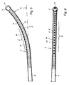
Fig. 6 den distalen Teil einer Ausführungsvariante des erfindungsgemäßen Führungskatheter in einer Seitenansicht und in einer Draufsicht. - Die in
Fig. 1 dargestellte Vorrichtung für den Transfer von Embryonen in den Uterus weist einen Führungskatheter 1 mit einem darin verschiebbar gehaltenen Innenkatheter 2 aus Kunststoff auf. Der Führungskatheter 1 ist zumindest an seinem distalen Ende biegeweich ausgeführt und weist ein Führungselement 3 in Form einer im Wesentlichen kugelförmigen Endkappe mit distaler Öffnung 13 auf. Der Führungskatheter 1 mit einer Gesamtlänge von ca. 20 cm besteht hauptsächlich aus einem Metallrohr 4, an dessen distalem Ende eine das Führungselement 3 tragende, kurze Spiralfeder 5 von ca. 17 mm bis 20 mm befestigt ist. Das Metallrohr 4 mit einem Außendurchmesser von z.B. 2 mm und einer Wandstärke von ca. 0,4 mm bis 0,5 mm besteht bevorzugt aus einem nahtlosen, weichgeglühten Edelstahlrohr (1.4404) und kann daher vor der Anwendung vom Arzt an die jeweilige Uterusanatomie angepasst, d.h. mit einer Krümmung 6 (sieheFig. 3 ) versehen werden. - Um die Lage bzw. die Position des Führungskatheters 1 während des Einführens in den Uterus besser kontrollieren zu können, sind im distalen Bereich des Metallrohrs 4 mehrere Distanzmarkierungen 7 (z.B. im Zentimeterabstand) angeordnet. Diese ermöglichen es dem Arzt die Eindringtiefe des Katheters zusätzlich zum Ultraschall zu kontrollieren. Dies ist insbesondere für jene Fälle wichtig, bei welchen die Ultraschallkontrolle wegen extrem adipöser Patientinnen nicht oder nur erschwert möglich ist. Weiters sind die Markierungen 7 des Führungskatheters 1 auch für die Uterussondierung bzw. Uterusvermessung verwendbar.
- Wie insbesondere in der Detaildarstellung gemäß
Fig. 2 erkennbar, liegen die Windungen 8 der bevorzugt aus Edelstahl (1.4310) bestehenden Spiralfeder 5 in unbelastetem Zustand aneinander an, so dass ein durchgehendes Lumen 9 für den hier nicht dargestellten Innenkatheter entsteht. Die Spiralfeder 5 mit einem Außendurchmesser von ca. 2,1 mm und einer Drahtstärke von 0,3 mm ist einerseits mit dem distalen Ende des Metallrohrs 4 und andererseits mit dem Führungselement 3 mittels Lasertechnologie verschweißt. Dazu weist das Metallrohr 4 eine endseitige Abstufung 10 in der Wandstärke auf, auf welche die Spiralfeder 5 aufgeschoben und verschweißt ist, so dass an der Außenseite des Führungskatheters 1 ein im Wesentlichen stufenloser Übergang vom Metallrohr 4 zur Spiralfeder 5 erfolgt. - Am proximalen Ende des Metallrohrs 4 ist ein Spritzenadapter 11, vorzugsweise ein Luer-Anschluss, befestigt. Dieser besteht im dargestellten Beispiel aus Edelstahl (1.4310) und weist eine Ausnehmung 12 auf, in die das proximale Ende des Metallrohrs 4 mittels Lasertechnologie eingeschweißt ist.
- Das Metallrohr 4 des Führungskatheters 1 wird in der Ausführungsvariante gemäß
Fig. 3 vom Arzt vor der Anwendung entsprechend der Uterusanatomie verformt, so dass eine Krümmung 6 im distalen Bereich entsteht und die Katheterspitze im Bezug auf das proximale Ende des Führungskatheters um einen Winkel α von ca. 15° bis 45° angehoben wird. Bevorzugt weist der Führungskatheters 1 bereits im Lieferzustand (in der Originalverpackung) eine der durchschnittlichen Uterusanatomie entsprechende Krümmung 6 auf, so dass der behandelnde Arzt nur noch geringfügige Anpassungen vornehmen muss. - Durch die vorgeformte Krümmung 6 und die weiche Spiralfeder 5 lässt sich der Führungskatheter 1 wesentlich leichter in den Zervikalkanal (siehe
Fig. 4 ) einführen, wobei das an der Spitze der Spiralfeder 5 angeordnete kugelförmige Führungselement 3 an der Wand des Zervikalkanals entlang gleitet. Nach Erreichen der optimalen Lage des Führungskatheters 1, welche mit Hilfe der Markierungen 7 und/oder im Ultraschallbild kontrolliert werden kann, wird der Innenkatheter 2 bis in etwa 1 cm Entfernung zum Uterusfundus vorgeschoben und der Embryo E in den Uterus entlassen. - Ein weiterer Vorteil der erfindungsgemäßen Vorrichtung besteht in der weitgehenden Vermeidung einer Kontamination des Innenkatheters 2 mit Bakterien oder Pilzen, da dieser durch die Umhüllung durch den Führungskatheter 1 mit dem äußeren Muttermund und dem Zervikalkanal nicht in Berührung kommt.
- In der Ausführungsvariante gemäß
Fig. 5 und Fig. 6 weist die Spiralfeder 5 im Bereich zwischen dem Metallrohr 4 und dem Führungselement 3 entlang deren Längsachse eine eingeprägte Krümmung 6' auf, wobei zur Herstellung der Krümmung 6' vorzugsweise mittels Lasertechnologie hergestellte Schweißpunkte 14 dienen, die nur einzelne Paare benachbarter Windungen 8 der Spiralfeder 5 verbinden, andere jedoch unverbunden belassen, so dass die Spiralfeder 5 weiter beweglich bleibt. Die Schweißpunkte 14 sind entlang einer Mantellinie parallel zur Achse der Feder angeordnet, so dass sich die dargestellte Krümmung 6' einstellt. Die Krümmung 6' der Spiralfeder 5 könnte auch mit Hilfe eines entsprechend gekrümmten Dorns hergestellt werden, auf welchen der Federdraht aufgewickelt wird. - Die Spiralfeder 5 bei den Ausführungsvarianten gemäß
Fig. 5 und Fig. 6 weist eine Länge im Bereich von 3,5 cm bis 5,5 cm auf und weist am distalen Ende eine im Wesentlichen zylindrische Endkappe 3 auf, die im Bereich der distalen Öffnung 13 abgerundet ist. Für die Anwendung bei Patientinnen mit besonders engem äußeren Muttermund kann der Durchmesser der zylindrische Endkappe 3 im Bereich des äußeren Durchmessers der Spiralfeder 5 (ca. 2,1 mm bis 2,5 mm) liegen. - Die erfindungsgemäße Vorrichtung zeichnet sich durch eine wesentlich erhöhte Erfolgsrate bei der In-Virto-Fertilisierung aus.
Claims (13)
- Vorrichtung für den uterinen Embryonentransfer mit einem Führungskatheter (1) und einem in diesem geführten Innenkatheter (2), wobei der Führungskatheter (1) an seinem distalen Ende biegeweich ausgeführt ist und ein Führungselement (3) mit einer distalen Öffnung (13) aufweist, dadurch gekennzeichnet, dass der Führungskatheter (1) aus einem Metallrohr (4) besteht, an dessen proximalem Ende ein Spritzenadapter (11) und an dessen distalem Ende im Wesentlichen stufenlos eine das Führungselement (3) tragende Spiralfeder (5) befestigt ist.
- Vorrichtung nach Anspruch 1, dadurch gekennzeichnet, dass das Metallrohr (4) zumindest in seinem distalen Bereich, bevorzugt im ganzen Bereich, verformbar ist und dessen Krümmung (6) vor der Anwendung vom Arzt an die jeweilige Uterusanatomie anpassbar ist.
- Vorrichtung nach Anspruch 1, dadurch gekennzeichnet, dass die Spiralfeder (5) im Bereich zwischen dem Metallrohr (4) und dem Führungselement (3) entlang deren Längsachse eine eingeprägte Krümmung (6') aufweist.
- Vorrichtung nach Anspruch 3, dadurch gekennzeichnet, dass die Spiralfeder (5) zur Herstellung der Krümmung (6') vorzugsweise mittels Lasertechnologie hergestellte Schweißpunkte (14) aufweist, die einzelne Paare benachbarter Windungen (8) der Spiralfeder (5) verbinden.
- Vorrichtung nach einem der Ansprüche 1 bis 4, dadurch gekennzeichnet, dass das Führungselement (3) als kugelförmige Endkappe mit einer distalen Öffnung (13) ausgeführt ist.
- Vorrichtung nach einem der Ansprüche 1 bis 4, dadurch gekennzeichnet, dass das Führungselement (3) als zylindrische Endkappe ausgeführt ist, die im Bereich der distalen Öffnung (13) abgerundet ist.
- Vorrichtung nach einem der Ansprüche 1 bis 6, dadurch gekennzeichnet, dass die Spiralfeder (5) aus Metall, vorzugsweise aus Edelstahl gefertigt ist.
- Vorrichtung nach einem der Ansprüche 1 bis 7, dadurch gekennzeichnet, dass die Windungen (8) der Spiralfeder (5) in unbelastetem Zustand aneinander anliegen
- Vorrichtung nach einem der Ansprüche 1 bis 8, dadurch gekennzeichnet, dass das Metallrohr (4) aus einem nahtlosen, weichgeglühten Edelstahlrohr besteht.
- Vorrichtung nach einem der Ansprüche 1 bis 9, dadurch gekennzeichnet, dass die Spiralfeder (5) einerseits mit dem distalen Ende des Metallrohrs (4) und andererseits mit dem Führungselement (3) mittels Lasertechnologie verschweißt ist.
- Vorrichtung nach einem der Ansprüche 1 bis 10, dadurch gekennzeichnet, dass im distalen Bereich des Metallrohrs (4) Distanzmarkierungen (7) angeordnet sind.
- Vorrichtung nach einem der Ansprüche 1 bis 11, dadurch gekennzeichnet, dass der Spritzenadapter (11) ein Luer-Anschluss ist.
- Vorrichtung nach einem der Ansprüche 1 bis 12, dadurch gekennzeichnet, dass der Spritzenadapter (11) aus Edelstahl gefertigt ist.
Priority Applications (1)
| Application Number | Priority Date | Filing Date | Title |
|---|---|---|---|
| AT06450032T ATE435618T1 (de) | 2005-05-10 | 2006-03-09 | Katheter zum uterinen embryonentransfer |
Applications Claiming Priority (1)
| Application Number | Priority Date | Filing Date | Title |
|---|---|---|---|
| AT0079705A AT501283B8 (de) | 2005-05-10 | 2005-05-10 | Vorrichtung für den uterinen embryonentransfer |
Publications (2)
| Publication Number | Publication Date |
|---|---|
| EP1721579A1 EP1721579A1 (de) | 2006-11-15 |
| EP1721579B1 true EP1721579B1 (de) | 2009-07-08 |
Family
ID=36603614
Family Applications (1)
| Application Number | Title | Priority Date | Filing Date |
|---|---|---|---|
| EP06450032A Expired - Lifetime EP1721579B1 (de) | 2005-05-10 | 2006-03-09 | Katheter zum uterinen Embryonentransfer |
Country Status (3)
| Country | Link |
|---|---|
| EP (1) | EP1721579B1 (de) |
| AT (2) | AT501283B8 (de) |
| DE (1) | DE502006004159D1 (de) |
Cited By (2)
| Publication number | Priority date | Publication date | Assignee | Title |
|---|---|---|---|---|
| RU185028U1 (ru) * | 2018-05-10 | 2018-11-19 | Денис Васильевич Огородников | Устройство для переноса эмбриона |
| RU187500U1 (ru) * | 2018-10-03 | 2019-03-11 | Денис Васильевич Огородников | Инструмент для эмбриотрансплантации |
Families Citing this family (7)
| Publication number | Priority date | Publication date | Assignee | Title |
|---|---|---|---|---|
| FR3011728B1 (fr) * | 2013-10-10 | 2017-08-11 | Prodimed | Dispositif de transfert gynecologique |
| WO2016101226A1 (zh) * | 2014-12-25 | 2016-06-30 | 河北农业大学 | 一种胚胎移植器及其操作方法 |
| CN106344131B (zh) * | 2016-08-31 | 2019-06-28 | 郑州大学第一附属医院 | 一种卵巢组织切片推送装置 |
| FR3097425A1 (fr) * | 2019-06-24 | 2020-12-25 | Anecova S.A. | Dispositif de protection pour dispositif médical |
| GR1009914B (el) * | 2020-03-03 | 2021-01-19 | Ελευθεριος Νικολαου Μεριδης | Καθετηρας μεταφορας ανθρωπινων εμβρυων με τμημα εγκαρσιων πτυχωσεων και εργονομικη λαβη |
| CN112516434B (zh) * | 2020-11-30 | 2022-04-22 | 临沂市兴华医用器材有限公司 | 一种麻醉导管 |
| CN117180592B (zh) * | 2023-09-06 | 2025-01-07 | 常州乐奥医疗科技股份有限公司 | 新型灌洗导管 |
Family Cites Families (7)
| Publication number | Priority date | Publication date | Assignee | Title |
|---|---|---|---|---|
| US735400A (en) * | 1903-04-22 | 1903-08-04 | Richard P Mccully | Surgical instrument. |
| US4004588A (en) | 1975-05-21 | 1977-01-25 | Wrightson Nma Limited | Apparatus for flushing ova from cows or mares |
| DE3473832D1 (en) * | 1983-06-14 | 1988-10-13 | Fertility & Genetics Ass | Non-surgical apparatus for human embryo transfer |
| DE9107792U1 (de) * | 1991-06-25 | 1991-09-12 | Labotect-Labor-Technik, Göttingen, GmbH, 3406 Bovenden | Instrumentensatz zum uterinen Embryonentransfer |
| EP0732954B1 (de) * | 1993-12-10 | 1998-08-19 | Schneider (Usa) Inc. | Führungskatheter |
| US6068623A (en) * | 1997-03-06 | 2000-05-30 | Percusurge, Inc. | Hollow medical wires and methods of constructing same |
| US6527752B1 (en) | 1999-09-24 | 2003-03-04 | Cook Urological, Inc. | Embryo transfer catheter |
-
2005
- 2005-05-10 AT AT0079705A patent/AT501283B8/de not_active IP Right Cessation
-
2006
- 2006-03-09 DE DE502006004159T patent/DE502006004159D1/de not_active Expired - Lifetime
- 2006-03-09 EP EP06450032A patent/EP1721579B1/de not_active Expired - Lifetime
- 2006-03-09 AT AT06450032T patent/ATE435618T1/de active
Cited By (2)
| Publication number | Priority date | Publication date | Assignee | Title |
|---|---|---|---|---|
| RU185028U1 (ru) * | 2018-05-10 | 2018-11-19 | Денис Васильевич Огородников | Устройство для переноса эмбриона |
| RU187500U1 (ru) * | 2018-10-03 | 2019-03-11 | Денис Васильевич Огородников | Инструмент для эмбриотрансплантации |
Also Published As
| Publication number | Publication date |
|---|---|
| AT501283B1 (de) | 2006-08-15 |
| AT501283B8 (de) | 2007-02-15 |
| EP1721579A1 (de) | 2006-11-15 |
| AT501283A4 (de) | 2006-08-15 |
| DE502006004159D1 (de) | 2009-08-20 |
| ATE435618T1 (de) | 2009-07-15 |
Similar Documents
| Publication | Publication Date | Title |
|---|---|---|
| EP0330843B1 (de) | Verfahren und Vorrichtung zum Entfernen von Ablagerungen in Gefässen und Organen von Lebewesen | |
| EP0593948B1 (de) | Stent-Set | |
| DE60311414T2 (de) | Katheter mit geformter rampe für führungsdraht | |
| DE69636674T2 (de) | Vorrichtung zur wärmebehandlung von gewebe | |
| DE69738235T2 (de) | Hybrider, rohrförmiger katheterführungsdraht | |
| DE60315833T2 (de) | Katheter mit Seitenwandlumenausgang und Herstellungsverfahren | |
| DE69732742T2 (de) | Rohrförmige medizinische Vorrichtung | |
| DE69518585T3 (de) | Vaskulärer Katheter | |
| DE68913897T2 (de) | Vorrichtung zur Einführung eines Dauererweiterungsgerätes für den Harnleiter. | |
| DE69128824T2 (de) | Injektionskatheter | |
| DE69731484T2 (de) | Lenkungsvorrichtung und verfahren für einen katheter und/oder führungsdraht | |
| DE602004013288T2 (de) | Dilatationsvorrichtung mit einem ausdehnbaren teil | |
| EP0242711B1 (de) | Katheter zur künstlichen Befruchtung | |
| DE102018208564A1 (de) | Steuerbare Einführungshülse | |
| DE60015742T2 (de) | Medizinische elektrodenleitung | |
| DE202017007707U1 (de) | Punktionsvorrichtung und Verankerungsvorrichtung | |
| WO1995020418A1 (en) | Catheter and method for depositing reproductive material into the reproductive tract of a female | |
| DE3922126A1 (de) | Infusionskatheter | |
| JPH07503883A (ja) | 無外傷性薬物送達先端部を有するカテーテル | |
| DE2005167B2 (de) | Postoperative Drain-Röhre | |
| EP0766977A1 (de) | Katheter | |
| DE3334546A1 (de) | Fuehrungssonde fuer eine schlauchanordnung zum einleiten und absaugen von fluiden in und aus dem magendarmtrakt eines patienten | |
| EP2401020B1 (de) | Katheter | |
| DE3107392A1 (de) | Medizinisches instrument | |
| AU2018241145B2 (en) | Connector device for gastric calibration hoses, as well as medical system comprising a connector device for gastric calibration hoses and a gastric calibration hose |
Legal Events
| Date | Code | Title | Description |
|---|---|---|---|
| PUAI | Public reference made under article 153(3) epc to a published international application that has entered the european phase |
Free format text: ORIGINAL CODE: 0009012 |
|
| AK | Designated contracting states |
Kind code of ref document: A1 Designated state(s): AT BE BG CH CY CZ DE DK EE ES FI FR GB GR HU IE IS IT LI LT LU LV MC NL PL PT RO SE SI SK TR |
|
| AX | Request for extension of the european patent |
Extension state: AL BA HR MK YU |
|
| AKX | Designation fees paid | ||
| 17P | Request for examination filed |
Effective date: 20070505 |
|
| RBV | Designated contracting states (corrected) |
Designated state(s): AT BE BG CH CY CZ DE DK EE ES FI FR GB GR HU IE IS IT LI LT LU LV MC NL PL PT RO SE SI SK TR |
|
| 17Q | First examination report despatched |
Effective date: 20070710 |
|
| REG | Reference to a national code |
Ref country code: DE Ref legal event code: 8570 |
|
| GRAP | Despatch of communication of intention to grant a patent |
Free format text: ORIGINAL CODE: EPIDOSNIGR1 |
|
| GRAS | Grant fee paid |
Free format text: ORIGINAL CODE: EPIDOSNIGR3 |
|
| GRAA | (expected) grant |
Free format text: ORIGINAL CODE: 0009210 |
|
| AK | Designated contracting states |
Kind code of ref document: B1 Designated state(s): AT BE BG CH CY CZ DE DK EE ES FI FR GB GR HU IE IS IT LI LT LU LV MC NL PL PT RO SE SI SK TR |
|
| REG | Reference to a national code |
Ref country code: GB Ref legal event code: FG4D Free format text: NOT ENGLISH |
|
| REG | Reference to a national code |
Ref country code: CH Ref legal event code: EP |
|
| REG | Reference to a national code |
Ref country code: IE Ref legal event code: FG4D |
|
| REF | Corresponds to: |
Ref document number: 502006004159 Country of ref document: DE Date of ref document: 20090820 Kind code of ref document: P |
|
| PG25 | Lapsed in a contracting state [announced via postgrant information from national office to epo] |
Ref country code: SI Free format text: LAPSE BECAUSE OF FAILURE TO SUBMIT A TRANSLATION OF THE DESCRIPTION OR TO PAY THE FEE WITHIN THE PRESCRIBED TIME-LIMIT Effective date: 20090708 |
|
| NLV1 | Nl: lapsed or annulled due to failure to fulfill the requirements of art. 29p and 29m of the patents act | ||
| PG25 | Lapsed in a contracting state [announced via postgrant information from national office to epo] |
Ref country code: LT Free format text: LAPSE BECAUSE OF FAILURE TO SUBMIT A TRANSLATION OF THE DESCRIPTION OR TO PAY THE FEE WITHIN THE PRESCRIBED TIME-LIMIT Effective date: 20090708 Ref country code: FI Free format text: LAPSE BECAUSE OF FAILURE TO SUBMIT A TRANSLATION OF THE DESCRIPTION OR TO PAY THE FEE WITHIN THE PRESCRIBED TIME-LIMIT Effective date: 20090708 Ref country code: ES Free format text: LAPSE BECAUSE OF FAILURE TO SUBMIT A TRANSLATION OF THE DESCRIPTION OR TO PAY THE FEE WITHIN THE PRESCRIBED TIME-LIMIT Effective date: 20091019 Ref country code: IS Free format text: LAPSE BECAUSE OF FAILURE TO SUBMIT A TRANSLATION OF THE DESCRIPTION OR TO PAY THE FEE WITHIN THE PRESCRIBED TIME-LIMIT Effective date: 20091108 |
|
| REG | Reference to a national code |
Ref country code: IE Ref legal event code: FD4D |
|
| PG25 | Lapsed in a contracting state [announced via postgrant information from national office to epo] |
Ref country code: PL Free format text: LAPSE BECAUSE OF FAILURE TO SUBMIT A TRANSLATION OF THE DESCRIPTION OR TO PAY THE FEE WITHIN THE PRESCRIBED TIME-LIMIT Effective date: 20090708 Ref country code: LV Free format text: LAPSE BECAUSE OF FAILURE TO SUBMIT A TRANSLATION OF THE DESCRIPTION OR TO PAY THE FEE WITHIN THE PRESCRIBED TIME-LIMIT Effective date: 20090708 Ref country code: NL Free format text: LAPSE BECAUSE OF FAILURE TO SUBMIT A TRANSLATION OF THE DESCRIPTION OR TO PAY THE FEE WITHIN THE PRESCRIBED TIME-LIMIT Effective date: 20090708 |
|
| PG25 | Lapsed in a contracting state [announced via postgrant information from national office to epo] |
Ref country code: PT Free format text: LAPSE BECAUSE OF FAILURE TO SUBMIT A TRANSLATION OF THE DESCRIPTION OR TO PAY THE FEE WITHIN THE PRESCRIBED TIME-LIMIT Effective date: 20091109 Ref country code: BG Free format text: LAPSE BECAUSE OF FAILURE TO SUBMIT A TRANSLATION OF THE DESCRIPTION OR TO PAY THE FEE WITHIN THE PRESCRIBED TIME-LIMIT Effective date: 20091008 |
|
| PG25 | Lapsed in a contracting state [announced via postgrant information from national office to epo] |
Ref country code: DK Free format text: LAPSE BECAUSE OF FAILURE TO SUBMIT A TRANSLATION OF THE DESCRIPTION OR TO PAY THE FEE WITHIN THE PRESCRIBED TIME-LIMIT Effective date: 20090708 Ref country code: IE Free format text: LAPSE BECAUSE OF FAILURE TO SUBMIT A TRANSLATION OF THE DESCRIPTION OR TO PAY THE FEE WITHIN THE PRESCRIBED TIME-LIMIT Effective date: 20090708 Ref country code: RO Free format text: LAPSE BECAUSE OF FAILURE TO SUBMIT A TRANSLATION OF THE DESCRIPTION OR TO PAY THE FEE WITHIN THE PRESCRIBED TIME-LIMIT Effective date: 20090708 Ref country code: EE Free format text: LAPSE BECAUSE OF FAILURE TO SUBMIT A TRANSLATION OF THE DESCRIPTION OR TO PAY THE FEE WITHIN THE PRESCRIBED TIME-LIMIT Effective date: 20090708 Ref country code: CZ Free format text: LAPSE BECAUSE OF FAILURE TO SUBMIT A TRANSLATION OF THE DESCRIPTION OR TO PAY THE FEE WITHIN THE PRESCRIBED TIME-LIMIT Effective date: 20090708 |
|
| PLBE | No opposition filed within time limit |
Free format text: ORIGINAL CODE: 0009261 |
|
| STAA | Information on the status of an ep patent application or granted ep patent |
Free format text: STATUS: NO OPPOSITION FILED WITHIN TIME LIMIT |
|
| PG25 | Lapsed in a contracting state [announced via postgrant information from national office to epo] |
Ref country code: SK Free format text: LAPSE BECAUSE OF FAILURE TO SUBMIT A TRANSLATION OF THE DESCRIPTION OR TO PAY THE FEE WITHIN THE PRESCRIBED TIME-LIMIT Effective date: 20090708 |
|
| 26N | No opposition filed |
Effective date: 20100409 |
|
| BERE | Be: lapsed |
Owner name: STEINER, HANS-PETER Effective date: 20100331 |
|
| PG25 | Lapsed in a contracting state [announced via postgrant information from national office to epo] |
Ref country code: MC Free format text: LAPSE BECAUSE OF NON-PAYMENT OF DUE FEES Effective date: 20100331 Ref country code: GR Free format text: LAPSE BECAUSE OF FAILURE TO SUBMIT A TRANSLATION OF THE DESCRIPTION OR TO PAY THE FEE WITHIN THE PRESCRIBED TIME-LIMIT Effective date: 20091009 |
|
| REG | Reference to a national code |
Ref country code: CH Ref legal event code: PL |
|
| PG25 | Lapsed in a contracting state [announced via postgrant information from national office to epo] |
Ref country code: LI Free format text: LAPSE BECAUSE OF NON-PAYMENT OF DUE FEES Effective date: 20100331 Ref country code: BE Free format text: LAPSE BECAUSE OF NON-PAYMENT OF DUE FEES Effective date: 20100331 Ref country code: CH Free format text: LAPSE BECAUSE OF NON-PAYMENT OF DUE FEES Effective date: 20100331 |
|
| PG25 | Lapsed in a contracting state [announced via postgrant information from national office to epo] |
Ref country code: IT Free format text: LAPSE BECAUSE OF FAILURE TO SUBMIT A TRANSLATION OF THE DESCRIPTION OR TO PAY THE FEE WITHIN THE PRESCRIBED TIME-LIMIT Effective date: 20090708 |
|
| PGFP | Annual fee paid to national office [announced via postgrant information from national office to epo] |
Ref country code: AT Payment date: 20110506 Year of fee payment: 6 |
|
| PG25 | Lapsed in a contracting state [announced via postgrant information from national office to epo] |
Ref country code: CY Free format text: LAPSE BECAUSE OF FAILURE TO SUBMIT A TRANSLATION OF THE DESCRIPTION OR TO PAY THE FEE WITHIN THE PRESCRIBED TIME-LIMIT Effective date: 20090708 |
|
| PG25 | Lapsed in a contracting state [announced via postgrant information from national office to epo] |
Ref country code: LU Free format text: LAPSE BECAUSE OF NON-PAYMENT OF DUE FEES Effective date: 20100309 Ref country code: HU Free format text: LAPSE BECAUSE OF FAILURE TO SUBMIT A TRANSLATION OF THE DESCRIPTION OR TO PAY THE FEE WITHIN THE PRESCRIBED TIME-LIMIT Effective date: 20100109 Ref country code: SE Free format text: LAPSE BECAUSE OF FAILURE TO SUBMIT A TRANSLATION OF THE DESCRIPTION OR TO PAY THE FEE WITHIN THE PRESCRIBED TIME-LIMIT Effective date: 20090708 |
|
| PG25 | Lapsed in a contracting state [announced via postgrant information from national office to epo] |
Ref country code: TR Free format text: LAPSE BECAUSE OF FAILURE TO SUBMIT A TRANSLATION OF THE DESCRIPTION OR TO PAY THE FEE WITHIN THE PRESCRIBED TIME-LIMIT Effective date: 20090708 |
|
| REG | Reference to a national code |
Ref country code: AT Ref legal event code: MM01 Ref document number: 435618 Country of ref document: AT Kind code of ref document: T Effective date: 20120309 |
|
| PG25 | Lapsed in a contracting state [announced via postgrant information from national office to epo] |
Ref country code: AT Free format text: LAPSE BECAUSE OF NON-PAYMENT OF DUE FEES Effective date: 20120309 |
|
| REG | Reference to a national code |
Ref country code: FR Ref legal event code: PLFP Year of fee payment: 11 |
|
| REG | Reference to a national code |
Ref country code: FR Ref legal event code: PLFP Year of fee payment: 12 |
|
| PGFP | Annual fee paid to national office [announced via postgrant information from national office to epo] |
Ref country code: FR Payment date: 20170330 Year of fee payment: 12 |
|
| PGFP | Annual fee paid to national office [announced via postgrant information from national office to epo] |
Ref country code: GB Payment date: 20170330 Year of fee payment: 12 |
|
| PGFP | Annual fee paid to national office [announced via postgrant information from national office to epo] |
Ref country code: DE Payment date: 20180530 Year of fee payment: 13 |
|
| GBPC | Gb: european patent ceased through non-payment of renewal fee |
Effective date: 20180309 |
|
| PG25 | Lapsed in a contracting state [announced via postgrant information from national office to epo] |
Ref country code: GB Free format text: LAPSE BECAUSE OF NON-PAYMENT OF DUE FEES Effective date: 20180309 |
|
| PG25 | Lapsed in a contracting state [announced via postgrant information from national office to epo] |
Ref country code: FR Free format text: LAPSE BECAUSE OF NON-PAYMENT OF DUE FEES Effective date: 20180331 |
|
| REG | Reference to a national code |
Ref country code: DE Ref legal event code: R119 Ref document number: 502006004159 Country of ref document: DE |
|
| PG25 | Lapsed in a contracting state [announced via postgrant information from national office to epo] |
Ref country code: DE Free format text: LAPSE BECAUSE OF NON-PAYMENT OF DUE FEES Effective date: 20191001 |