EP1721019B1 - Verfahren zur herstellung einer sinterrohmischung - Google Patents
Verfahren zur herstellung einer sinterrohmischung Download PDFInfo
- Publication number
- EP1721019B1 EP1721019B1 EP05715471A EP05715471A EP1721019B1 EP 1721019 B1 EP1721019 B1 EP 1721019B1 EP 05715471 A EP05715471 A EP 05715471A EP 05715471 A EP05715471 A EP 05715471A EP 1721019 B1 EP1721019 B1 EP 1721019B1
- Authority
- EP
- European Patent Office
- Prior art keywords
- mixer
- sintered material
- mixing
- installation according
- returned sintered
- Prior art date
- Legal status (The legal status is an assumption and is not a legal conclusion. Google has not performed a legal analysis and makes no representation as to the accuracy of the status listed.)
- Expired - Lifetime
Links
Images


Classifications
-
- C—CHEMISTRY; METALLURGY
- C22—METALLURGY; FERROUS OR NON-FERROUS ALLOYS; TREATMENT OF ALLOYS OR NON-FERROUS METALS
- C22B—PRODUCTION AND REFINING OF METALS; PRETREATMENT OF RAW MATERIALS
- C22B1/00—Preliminary treatment of ores or scrap
- C22B1/14—Agglomerating; Briquetting; Binding; Granulating
- C22B1/16—Sintering; Agglomerating
-
- C—CHEMISTRY; METALLURGY
- C22—METALLURGY; FERROUS OR NON-FERROUS ALLOYS; TREATMENT OF ALLOYS OR NON-FERROUS METALS
- C22B—PRODUCTION AND REFINING OF METALS; PRETREATMENT OF RAW MATERIALS
- C22B1/00—Preliminary treatment of ores or scrap
- C22B1/14—Agglomerating; Briquetting; Binding; Granulating
- C22B1/16—Sintering; Agglomerating
- C22B1/20—Sintering; Agglomerating in sintering machines with movable grates
-
- C—CHEMISTRY; METALLURGY
- C22—METALLURGY; FERROUS OR NON-FERROUS ALLOYS; TREATMENT OF ALLOYS OR NON-FERROUS METALS
- C22B—PRODUCTION AND REFINING OF METALS; PRETREATMENT OF RAW MATERIALS
- C22B1/00—Preliminary treatment of ores or scrap
- C22B1/14—Agglomerating; Briquetting; Binding; Granulating
- C22B1/16—Sintering; Agglomerating
- C22B1/20—Sintering; Agglomerating in sintering machines with movable grates
- C22B1/205—Sintering; Agglomerating in sintering machines with movable grates regulation of the sintering process
-
- C—CHEMISTRY; METALLURGY
- C22—METALLURGY; FERROUS OR NON-FERROUS ALLOYS; TREATMENT OF ALLOYS OR NON-FERROUS METALS
- C22B—PRODUCTION AND REFINING OF METALS; PRETREATMENT OF RAW MATERIALS
- C22B1/00—Preliminary treatment of ores or scrap
- C22B1/14—Agglomerating; Briquetting; Binding; Granulating
- C22B1/24—Binding; Briquetting ; Granulating
- C22B1/242—Binding; Briquetting ; Granulating with binders
Definitions
- the invention relates to a method for producing a sintering raw mixture containing ore with a fine fraction, at least one additive, sintered material from a subsequent sintering process and optionally a binder, by mixing and granulating, and a plant for carrying out the method.
- the sintered material is extremely abrasive and requires a high degree of wear of the system components with which the sintered material comes into contact when producing the sintering raw mixture.
- there is a significantly increased wear of such equipment parts when trying to achieve a high flow rate per unit time. It then comes to premature wear of equipment parts and thus to a poor efficiency of a plant for producing such Sinterrohhmischept.
- the invention therefore has as its object to provide a method and an apparatus for carrying out the method, which allow high throughput rates despite the return of sintered material, but operating stoppages can be avoided by the failure of essential system parts or result in maintenance intervals in not too close intervals ,
- This object is achieved in that the sintered material is added after mixing the ore with the aggregate and with the optionally provided binder.
- the addition of the recycled material is advantageous immediately before granulation or only during granulation for the course of the granulation because, on the one hand, the coarser particles of the sintered backbone act as a nucleus for the granules to be formed and because, on the other hand, the fine fraction of the recycled material is a necessary constituent for the granules Formation of the granules during the rolling process is used.
- the sintered material is added before granulation.
- this does not mean that the sintered material is already added during mixing, if the first granules should form during mixing. Rather, the sintered material is added before a so-called final granulation process in which granules of the desired size are formed from the mix, even if the mix already contains some smaller granules formed during mixing.
- the sintered material can be added, for example, on the transport path of the mixed material from a mixing device to a granulator.
- the sintered material is added during the granulation process, preferably during the final granulation process.
- the admixture of the sinter backings is variable, i. from after mixing until just before the completion of the granules adjustable.
- the method is very adaptable to the different operating conditions. For example, a part of the sinter backbone before granulation and a part during granulation may be added.
- a fuel is added at a stage of granulation in which forming green granules have the desired size for further processing, as described for example in the Austrian patent application A 1110/2003 is set forth.
- the mixing is carried out as intensive mixing, wherein the mix in a container by means of a Blending tool is mixed, wherein between the container and the mixing tool, a relative movement takes place.
- intensive mixing has been shown that the wear by sintered material occurs in a particularly high degree, so that a combination of intensive mixing with a return of the Sinter Weggut after intensive mixing is particularly advantageous.
- Intensive mixing enables particularly high throughput rates to be achieved. This results in a particularly violent and rapid approximation of the particles to be mixed, so that a subsequent granulation process is also accelerated.
- Another advantage lies in the homogeneous distribution of the mixed particles, whereby a very good quality of a sintered material is ensured.
- the inventive measure a load of an intensive mixer is avoided by the Sinterschreibgut.
- a plant for producing a sintering raw mixture containing ore with a fine fraction, at least one additive, sintered material from a subsequent sintering process and optionally a binder, which plant has a mixer for the ore, the aggregate and optionally added binder, which is arranged downstream of a pelletizer is characterized in that the pelletizing device is designed as a granulating and that a sintered remindgut the mixture feeding conveyor is provided.
- the conveyor for sintered material returns to a conveyor, which leads from the mixer to the granulating.
- a sintered material returning recirculating conveyor projecting into the granulating wherein advantageously the delivery point of the conveyor for the sintered material within the longitudinal extent of the granulating and variable and further expedient the conveying speed of the conveyor for the sintered material is variable.
- a mixer drum mixer can be used, a particularly preferred variant, however, is characterized in that the mixer as an intensive mixer is formed, wherein the mixer has a container into which a mixing tool protrudes, and between the container and the mixer tool, a relative movement is adjustable.
- the mixer is expediently designed as a horizontal or vertical shaft mixer with blades or paddles arranged on at least one shaft.
- an adding device for fuel such as coke
- the discharge point of the feed device is provided in the conveying direction of the sintering raw mixture to the discharge point for the sintered material.
- a first part of the device viewed in the throughput direction of the material to be mixed, is designed as a mixer, in particular as an intensive mixer, and a further part as a granulating drum.
- the invention allows, as already mentioned above, high performance.
- An installation according to the invention can therefore be designed for an output of more than 500 t / h of sintering raw mixture.
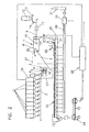
- ores and additives wherein also fuel, such as coke, may be present as aggregate, taken from juxtaposed bunkers 1 via weighing devices in the predetermined ratio and get from these to a collection device, such as a conveyor belt 2, which makes these materials Mixer 3 promotes, which is preferably installed express as a high-performance mixer, as will be described later.
- the materials are additionally added via a feed 4, a binder such as quicklime added.
- a binder such as quicklime added.
- water is added via a supply line 5 in a specific amount to optimize the mixing process and also the agglomeration process to be carried out subsequently in order to obtain a certain optimum moisture content.
- the mixture discharged from the mixer 3 passes via a conveying device, such as a conveyor belt 6, to a granulating device 7 in which the mixture is granulated and in which the required final moisture is also adjusted via a water feed 8.
- the material passes from one feed end of the granulating drum 7 to the opposite end of discharge, from where it is conveyed on for further processing, with increasing formation of green granules, which are to have a size preferably between 2 and 8 mm. Such further processing takes place - as described below - by sintering.
- the granulating drum 7 is arranged in the illustrated example in a horizontal position; However, it can also be arranged slightly inclined to increase the capacity. This also applies to the mixer 3.
- a feed device 9 for the fuel is provided at a certain point of the longitudinal extent of the granulating drum 7.
- This adding device 9 is preferably designed as a conveyor belt whose delivery point or discharge point 10 defines the region 11 to which the fuel is added to the green granules.
- the task of the fuel on the conveyor belt 9 is via a bunker 12, a weighing belt 13 and a feed chute 14.
- the fuel may be provided with a fine-grained binder, e.g. with quicklime, hydrated lime or slag.
- the conveyor belt 9 preferably projects into the granulating drum 7 via one end thereof and extends in the longitudinal direction of the granulating drum 7.
- the area 11 of the discharge of the fuel ie the range of the first contact of the fuel with the green granules, variable, which can be accomplished by changing the conveyor belt speed, so that the Abschparabel for the fuel is changed.
- This can also be achieved by moving the conveyor belt 9 in the longitudinal direction of the granulating drum 7, as illustrated by a double arrow 15 in the drawing.
- the mixer 3 is designed as a high-performance mixer and has a horizontal, driven shaft 16, on which radially outwardly extending paddles or blades 17 are arranged.
- a high-performance mixer When using such a high-performance mixer, the moisture of the green granules can be minimized, whereby an increase in productivity can be achieved on a sintering machine.
- the materials in the mixture are distributed particularly homogeneously, whereby a uniform quality of the final product is ensured. What is essential is the relative movement between the drum 18 of the high-performance mixer and the blades 17.
- the green pellets or green granules thus formed are subsequently fed via a conveyor 19 to a sintering machine 20, applied to the traveling grate 21 and sintered after ignition by means of a firing cap 22.
- the finished sintered material is coarsely crushed at the outlet end of the sintering machine 20 by means of a comminution device 23, then cooled by means of a cooling device 24 and transferred to a further comminution and screening plant 25.
- this crushing and screening plant 25 the coarsely crushed sintered material is further comminuted, usually by means of roll crushers. It comes to the formation of particles in the order of 0 to 50 mm.
- the particles which are smaller than about 5 mm, are collected as sintered material in a bunker 26 and added by this after weighing in a certain amount per unit time of the mixture leaving the mixer 3 - formed of ore, aggregate and binder -, namely on the mixer 3 with the granulating drum 7 connecting conveyor belt 6 abandoned, as is illustrated by a conveyor 27 shown schematically.
- the particles which preferably have a size between 10 and 20 mm, are supplied in a predetermined amount of the sintering machine 20 as a rust coating, as shown in the line 28. If the amount of the particles of this size exceeds the amount required for the rust coating, these particles are supplied with the other particles for further processing.
- the exhaust gas produced during the sintering process is supplied via a collecting line 29 to a gas cleaning device 30 and then discharged via a chimney 31.
- the sintered material is placed on a conveyor belt 32, which projects into the granulating drum 7 and dropped there at a predetermined point of the longitudinal extent of the granulating drum. It is possible to vary this point by longitudinal displacement of the conveyor belt 32.
- the mixer 3 is also designed as an intensive mixer, wherein in the container 33, one or more vertically arranged, driven by a motor M shafts 16 with paddles 17 protrude.
- FIG. 3 Another possibility of the abandonment of the sinter back is in Fig. 3 illustrated; the sintered material is returned according to Fig. 3 introduced through a chute 34 in the granulating drum 7.
- sinter back material after the mixing operation makes it possible to use the above-described intensive mixer 3, which allow high productivity and a reduction in energy consumption.
- sintering can be produced with very good and also stable quality, which in turn positively influences the productivity and the energy consumption during subsequent processing, for example in a blast furnace.
Landscapes
- Engineering & Computer Science (AREA)
- Chemical & Material Sciences (AREA)
- Manufacturing & Machinery (AREA)
- Geochemistry & Mineralogy (AREA)
- Geology (AREA)
- General Life Sciences & Earth Sciences (AREA)
- Life Sciences & Earth Sciences (AREA)
- Environmental & Geological Engineering (AREA)
- Materials Engineering (AREA)
- Mechanical Engineering (AREA)
- Metallurgy (AREA)
- Organic Chemistry (AREA)
- Manufacture And Refinement Of Metals (AREA)
Description
- Die Erfindung betrifft ein Verfahren zur Herstellung einer Sinterrohmischung, enthaltend Erz mit einem Feinanteil, mindestens einen Zuschlagstoff, Sinterrückgut aus einem nachfolgenden Sinterprozess und gegebenenfalls einen Binder, durch Mischen und Granulieren, sowie eine Anlage zur Durchführung des Verfahrens.
- Verfahren der eingangs beschriebenen Art sind beispielsweise bekannt aus der
EP 0 199 818 A1 , derJP 62-174333 A EP 0 415 146 A1 und aus ISIJ International, Vol 33 (1993), No. 4, Seiten 454 bis 461. Bei all diesen bekannten Verfahren ergibt sich durch das nach dem Sintern erforderliche Zerkleinern des Sintergutes ein Feinanteil des Sintergutes, der sich beim nachfolgenden Verarbeiten des gesinterten Erzes nachteilig auswirkt. Dieser Feinanteil, nachfolgend auch Sinterrückgut genannt, wird daher rückgeführt und dem Einsatzgut, also dem Erz mit einem Feinanteil und dem Zuschlagstoff, zugegeben, anschließend gemischt und erneut granuliert, sowie nachfolgend gesintert. - Das Sinterrückgut ist äußerst abrasiv und bedingt eine hohe Abnützung der Anlagenteile, mit denen das Sinterrückgut beim Herstellen der Sinterrohmischung in Kontakt gerät. Insbesondere ergibt sich eine wesentlich erhöhte Abnützung solcher Anlagenteile, wenn man versucht, eine hohe Durchsatzmenge pro Zeiteinheit zu erzielen. Es kommt dann zum vorzeitigen Verschleiß von Anlagenteilen und damit zu einem schlechten Nutzungsgrad einer Anlage zum Herstellen solcher Sinterrohmischungen.
- Die Erfindung stellt sich daher die Aufgabe, ein Verfahren und eine Vorrichtung zur Durchführung des Verfahrens zu schaffen, welche trotz Rückführung von Sinterrückgut hohe Durchsatzleistungen ermöglichen, wobei jedoch Betriebsstillstände durch den Ausfall wesentlicher Anlagenteile vermieden werden können bzw. sich Wartungsintervalle in nicht zu engen Abständen ergeben.
- Diese Aufgabe wird erfindungsgemäß dadurch gelöst, dass das Sinterrückgut nach dem Mischen des Erzes mit dem Zuschlagstoff und mit dem gegebenenfalls vorgesehenen Binder zugegeben wird.
- Es hat sich gezeigt, dass durch ein Überspringen des Mischverfahrens beim Rückführen des Sinterrückgutes die Verfügbarkeit einer Anlage zum Herstellen einer Sinterrohmischung extrem ansteigt und dass zudem enorme Leistungssteigerungen bei einer solchen Anlage erzielt werden können. So ist es möglich, mit einer Anlage einen Durchsatz von mehr als 500 t/h zu erreichen.
- Weiters ist die Zugabe des Rückgutes erst unmittelbar vor dem Granulieren oder erst während des Granulierens vorteilhaft für den Ablauf des Granuliervorganges, weil einerseits die gröberen Partikel des Sinterrückgutes als Nukleus für die zu bildenden Granulate fungieren und weil andererseits der Feinanteil des Rückgutes als notwendiger Bestandteil für die Bildung der Granulate während des Rolliervorganges dient.
- Gemäß einer ersten bevorzugten Ausführungsform wird das Sinterrückgut vor dem Granulieren zugegeben. Dies bedeutet jedoch nicht, dass das Sinterrückgut bereits beim Mischen zugesetzt wird, falls sich beim Mischen schon erste Granulate bilden sollten. Vielmehr wird das Sinterrückgut vor einem sogenannten Endgranulierungsprozess zugegeben, in dem Granulate der gewünschten Größe aus dem Mischgut gebildet werden, selbst wenn das Mischgut schon einige beim Mischen entstehende kleinere Granulate enthält. So kann das Sinterrückgut beispielsweise auf dem Transportweg des Mischgutes von einer Mischeinrichtung zu einer Granuliereinrichtung zugegeben werden.
- Gemäß einer weiteren bevorzugten Ausführungsform wird das Sinterrückgut während des Granulierprozesses, vorzugsweise während des Endgranulierprozesses, zugegeben.
- Vorzugsweise ist die Zumischung des Sinterrückgutes variierbar, d.h. von nach dem Mischen bis knapp vor Fertigstellung des Granulats einstellbar. Damit ist das Verfahren sehr anpassungsfähig an die unterschiedlichen Betriebszustände. Beispielsweise kann ein Teil des Sinterrückgutes vor dem Granulieren und ein Teil während des Granulierens beigegeben werden. Es ist jedoch auch möglich, bei Verwendung einer Granuliertrommel die Stelle, an der das Sinterrückgut in die Granuliertrommel eingebracht wird, variabel zu gestalten, sodass man entweder zu Beginn der Granulatbildung oder erst in einem späteren Verfahrensstadium das Sinterrückgut einbringen kann.
- Vorzugsweise wird ein Brennstoff in einem Stadium der Granulierung beigegeben, bei dem sich bildende Grüngranulate die für eine Weiterverarbeitung gewünschte Größe aufweisen, wie dies beispielsweise in der Österreichischen Patentanmeldung
A 1110/2003 - Gemäß einer besonders bevorzugten Ausführungsform wird das Mischen als Intensivmischen durchgeführt, bei dem das Mischgut in einem Behältnis mittels eines Mischwerkzeuges gemischt wird, wobei zwischen dem Behältnis und dem Mischwerkzeug eine Relativbewegung stattfindet. Gerade beim Intensivmischen hat sich gezeigt, dass die Abnützung durch Sinterrückgut in besonders hohem Maße auftritt, sodass eine Kombination des Intensivmischens mit einer Rückführung des Sinterrückgutes nach dem Intensivmischen besonders vorteilhaft ist. Durch das Intensivmischen lassen sich besonders hohe Durchsatzleistungen erzielen. Es kommt hierdurch nämlich zu einer besonders heftigen und schnellen Annäherung der zu mischenden Teilchen, sodass ein nachfolgender Granulierprozess ebenfalls beschleunigt abläuft. Ein weiterer Vorteil liegt in der homogenen Verteilung der gemischten Teilchen, wodurch eine sehr gute Qualität eines Sintergutes sichergestellt ist. Durch die erfindungsgemäße Maßnahme wird eine Belastung eines Intensivmischers durch das Sinterrückgut vermieden.
- Durch die Anwendung eines Intensivmischens erzielt man zudem an der Sinteranlage eine hohe Produktivität und eine Reduktion des Energieverbrauchs. Weiters ist es hierdurch möglich, den Sinter mit sehr guter und stabiler Qualität zu erzeugen, wodurch die Produktivität und der Energieverbrauch beim nachfolgenden Weiterverarbeiten eines gesinterten Erzes, beispielsweise in einem Hochofen, sehr positiv beeinflusst wird.
- Eine Anlage zur Herstellung einer Sinterrohmischung enthaltend Erz mit einem Feinanteil, mindestens einen Zuschlagstoff, Sinterrückgut aus einem nachfolgenden Sinterprozess und gegebenenfalls einen Binder, welche Anlage einen Mischer für das Erz, den Zuschlagstoff und den gegebenenfalls beigegebenen Binder aufweist, dem eine Pelletiereinrichtung nachgeordnet ist, ist dadurch gekennzeichnet, dass die Pelletiereinrichtung als Granuliertrommel ausgebildet ist und dass eine Sinterrückgut der Mischung zuführende Fördereinrichtung vorgesehen ist.
- Vorzugsweise führt die Fördereinrichtung für Sinterrückgut zu einer Fördereinrichtung, die vom Mischer zur Granuliertrommel führt.
- Es kann jedoch auch von Vorteil sein, wenn eine Sinterrückgut rückführende Fördereinrichtung in die Granuliertrommel ragt, wobei vorteilhaft die Abgabestelle der Fördereinrichtung für das Sinterrückgut innerhalb der Längserstreckung der Granuliertrommel variabel und wobei weiters zweckmäßig die Fördergeschwindigkeit der Fördereinrichtung für das Sinterrückgut variabel ist.
- Als Mischer kann ein Trommelmischer Verwendung finden, eine besonders bevorzugte Variante ist jedoch dadurch gekennzeichnet, dass der Mischer als Intensivmischer ausgebildet ist, wobei der Mischer ein Behältnis aufweist, in das ein Mischwerkzeug ragt, und zwischen dem Behältnis und dem Mischerwerkzeug eine Relativbewegung einstellbar ist.
- Hierbei ist zweckmäßig der Mischer als Horizontal- oder Vertikalwellenmischer mit an mindestens einer Welle angeordneten Schaufeln oder Paddeln ausgebildet.
- Vorzugsweise ist innerhalb der Granuliertrommel eine Zugabeeinrichtung für Brennstoff, wie Koks, vorgesehen, wobei die Abgabestelle der Zugabeeinrichtung in Förderrichtung der Sinterrohmischung nach der Abgabestelle für das Sinterrückgut vorgesehen ist.
- Es ist auch möglich, den Mischer mit der Granuliertrommel integral auszubilden, wobei ein in Durchsatzrichtung des zu mischenden Gutes gesehen erster Teil der Einrichtung als Mischer, insbesondere als Intensivmischer, und ein weiterer Teil als Granuliertrommel ausgebildet sind.
- Die Erfindung ermöglicht, wie bereits weiter oben erwähnt, hohe Leistungen. Eine erfindungsgemäße Anlage kann daher für eine Leistung von mehr als 500 t/h Sinterrohmischung ausgelegt sein.
- Die Erfindung ist nachfolgend anhand der in der Zeichnung in den
Fig. 1 bis 3 in schematischer Darstellung veranschaulichten Ausführungsbeispielen näher erläutert. - Gemäß der in
Fig. 1 dargestellten Ausführungsform werden Erze und Zuschlagsstoffe, wobei auch Brennstoff, wie z.B. Koks, als Zuschlagsstoff vorhanden sein kann, von nebeneinander angeordneten Bunkern 1 über Wiegeeinrichtungen im vorgegebenen Verhältnis entnommen und gelangen von diesen auf eine Sammeleinrichtung, wie ein Förderband 2, welches diese Materialien zu einem Mischer 3 fördert, der vorzugweise als Hochleistungsmischer, wie später noch beschrieben wird, augebildet ist. - Unmittelbar vor der Aufgabe dieser Materialien in den Mischer 3 wird den Materialien noch zusätzlich über eine Zuführung 4 ein Binder, wie z.B. Branntkalk, zugegeben. Im Mischer 3 wird zur Optimierung des Mischvorganges und auch des nachfolgend noch durchzuführenden Agglomeriervorganges Wasser über eine Zuleitung 5 in bestimmter Menge zugegeben, um eine bestimmte optimale Feuchte zu erhalten.
- Die aus dem Mischer 3 ausgetragene Mischung gelangt über eine Fördereinrichtung, wie ein Förderband 6, zu einer Granuliereinrichtung 7, in der die Mischung granuliert wird und in der auch die erforderliche Endfeuchte über eine Wasserzuführung 8 eingestellt wird. Das Material gelangt unter zunehmender Bildung von Grün-Granulaten, die schlussendlich vorzugsweise eine Größe zwischen 2 und 8 mm aufweisen sollen, von einem Aufgabe-Ende der Granuliertrommel 7 zum gegenüberliegenden Ausgabe-Ende, von wo sie zur Weiterverarbeitung weitergefördert werden. Eine solche Weiterverarbeitung erfolgt - wie nachfolgend beschrieben - durch Sintern.
- Die Granuliertrommel 7 ist im dargestellten Beispiel in horizontaler Lage angeordnet; sie kann jedoch auch zur Erhöhung der Förderleistung leicht geneigt angeordnet sein. Dies gilt auch für den Mischer 3.
- Vorzugsweise werden die Grün-Granulate - sogenannte Grün-Pellets - bei Erreichen ihrer optimalen Korngröße bis 8 mm mit einem feinkörnigen Brennstoff, vorzugsweise Feinkoks, ummantelt. Dies geschieht innerhalb der Granuliertrommel 7, in der eine Zugabeeinrichtung 9 für den Brennstoff an einer gewissen Stelle der Längserstreckung der Granuliertrommel 7 vorgesehen ist. Diese Zugabevorrichtung 9 ist vorzugsweise als Förderband ausgebildet, dessen Abgabestelle bzw. Abwurfstelle 10 den Bereich 11, an dem der Brennstoff den Grün-Granulaten beigegeben wird, festlegt. Die Aufgabe des Brennstoffs auf das Förderband 9 erfolgt über einen Bunker 12, ein Wiegeband 13 und eine Aufgabeschurre 14. Der Brennstoff kann mit einem feinkörnigen Binder versehen sein, wie z.B. mit Branntkalk, Hydratkalk oder Schlacke.
- Das Förderband 9 ragt vorzugsweise über ein Ende der Granuliertrommel 7 in diese hinein und erstreckt sich in Längsrichtung der Granuliertrommel 7.
- Anstelle des Förderbandes 9 könnten auch andere Zugabeeinrichtungen vorgesehen sein, beispielsweise ein Schneckenförderer oder ein Trogkettenförderer etc.
- Vorteilhaft ist der Bereich 11 des Abwurfs des Brennstoffs, d.h. der Bereich der ersten Kontaktnahme des Brennstoffs mit den Grün-Granulaten, variierbar, was durch Änderung der Förderbandgeschwindigkeit bewerkstelligt werden kann, sodass die Abwurfparabel für den Brennstoff geändert wird. Dies kann auch durch Verbringen des Förderbandes 9 in Längsrichtung der Granuliertrommel 7 erzielt werden, wie dies in der Zeichnung durch einen Doppelpfeil 15 veranschaulicht ist.
- Ab dem Bereich der ersten Kontaktnahme der Grün-Granulate mit dem Brennstoff werden diese mit dem Brennstoff ummantelt und dadurch stabilisiert; ein Weiterwachsen der Grün-Granulate wird somit verhindert. Ein gegebenenfalls vorhandener gröberer Anteil des Brennstoffes, also des vorzugsweise eingesetzten Kokses, wird zwischen den ummantelten Grün-Granulaten verteilt.
- Der Mischer 3 ist als Hochleistungsmischer ausgebildet und weist eine horizontale, angetriebene Welle 16 auf, an der sich radial nach außen erstreckende Paddel bzw. Schaufeln 17 angeordnet sind. Bei Verwendung eines solchen Hochleistungsmischers kann die Feuchte der Grün-Granulate minimiert werden, wodurch eine Steigerung der Produktivität auf einer Sintermaschine erzielt werden kann. Weiters werden die Materialien in der Mischung besonders homogen verteilt, wodurch eine gleichmäßige Qualität des Endproduktes sichergestellt ist. Wesentlich ist die Relativbewegung zwischen der Trommel 18 des Hochleistungsmischers und den Schaufeln 17.
- Die so gebildeten Grün-Pellets bzw. Grün-Granulate werden nachfolgend über eine Fördereinrichtung 19 einer Sintermaschine 20 zugeführt, auf deren Wanderrost 21 aufgebracht und nach Zünden mittels einer Zündhaube 22 gesintert. Das fertig gesinterte Gut wird am auslaufseitigen Ende der Sintermaschine 20 mittels einer Zerkleinerungseinrichtung 23 grob zerkleinert, anschließend mittels einer Kühleinrichtung 24 gekühlt und zu einer weiteren Zerkleinerungs- und Siebanlage 25 verbracht. In dieser Zerkleinerungs- und Siebanlage 25 wird das grobzerkleinerte Sintergut weiter zerkleinert, meist mittels Walzenbrecher. Es kommt zur Bildung von Teilchen in der Größenordnung zwischen 0 und 50 mm. Die Teilchen, die kleiner sind als etwa 5 mm, werden als Sinterrückgut in einem Bunker 26 gesammelt und von diesem nach Abwägen in einer bestimmten Menge pro Zeiteinheit dem aus dem Mischer 3 austretenden Mischgut - gebildet von Erz, Zuschlagstoff und Binder - beigefügt, und zwar auf das den Mischer 3 mit der Granuliertrommel 7 verbindende Förderband 6 aufgegeben, wie dies durch eine schematisch dargestellte Fördereinrichtung 27 veranschaulicht ist.
- Die Teilchen, die vorzugsweise eine Größe zwischen 10 und 20 mm aufweisen, werden in einer vorbestimmten Menge der Sintermaschine 20 als Rostbelag zugeführt, wie dies die Linie 28 zeigt. Übersteigt die Menge der Teilchen mit dieser Größe die für den Rostbelag erforderliche Menge, werden diese Teilchen mit den anderen Teilchen der Weiterverarbeitung zugeführt.
- Das beim Sintervorgang entstehende Abgas wird über eine Sammelleitung 29 einer Gasreinigungseinrichtung 30 zugeführt und anschließend über einen Schornstein 31 abgeführt.
- Gemäß
Fig. 2 wird das Sinterrückgut auf ein Förderband 32 aufgegeben, das in die Granuliertrommel 7 ragt und dort an einer vorbestimmten Stelle der Längserstreckung der Granuliertrommel abgeworfen. Es besteht die Möglichkeit, diese Stelle durch Längsverschieben des Förderbandes 32 zu variieren. - Gemäß der
Fig. 2 ist der Mischer 3 ebenfalls als Intensivmischer ausgebildet, wobei in den Behälter 33 eine oder mehrere vertikal angeordnete, von einem Motor M angetriebene Wellen 16 mit Paddeln 17 ragen. - Eine weitere Möglichkeit der Aufgabe des Sinterrückgutes ist in
Fig. 3 veranschaulicht; das Sinterrückgut wird gemäßFig. 3 über eine Schurre 34 in die Granuliertrommel 7 eingebracht. - Das Zugeben des Sinterrückgutes nach dem Mischvorgang ermöglicht es, die zuvor beschriebenen Intensivmischer 3 einzusetzen, die eine hohe Produktivität und eine Reduktion des Energieverbrauches ermöglichen. Zudem lässt sich Sinter mit sehr guter und auch stabiler Qualität produzieren, was wiederum die Produktivität und den Energieverbrauch beim anschließenden Weiterverarbeiten, beispielsweise in einem Hochofen, positiv beeinflusst.
Claims (16)
- Verfahren zur Herstellung einer Sinterrohmischung, enthaltend Erz mit einem Feinanteil, mindestens einen Zuschlagstoff, Sinterrückgut aus einem nachfolgenden Sinterprozess und gegebenenfalls einen Binder, durch Mischen und Granulieren, dadurch gekennzeichnet, dass das Sinterrückgut nach dem Mischen des Erzes mit dem Zuschlagstoff und mit dem gegebenenfalls vorgesehenen Binder zugegeben wird.
- Verfahren nach Anspruch 1, dadurch gekennzeichnet, dass Sinterrückgut vor dem Granulieren, vorzugsweise vor einem Endgranulierprozess, zugegeben wird.
- Verfahren nach Anspruch 1 oder 2, dadurch gekennzeichnet, dass Sinterrückgut während des Granulierprozesses, vorzugsweise während des Endgranulierprozesses, zugegeben wird.
- Verfahren nach einem oder mehreren der Ansprüche 1 bis 3, dadurch gekennzeichnet, dass die Zumischung des Sinterrückgutes variierbar ist, d.h. von nach dem Mischen bis knapp vor Fertigstellung des Granulats einstellbar ist.
- Verfahren nach einem oder mehreren der Ansprüche 1 bis 4, dadurch gekennzeichnet, dass ein Brennstoff in einem Stadium der Granulierung beigegeben wird, bei dem sich bildende Grüngranulate die für eine Weiterverarbeitung gewünschte Größe aufweisen.
- Verfahren nach einem oder mehreren der Ansprüche 1 bis 5, dadurch gekennzeichnet, dass das Mischen als Intensivmischen durchgeführt wird, bei dem das Mischgut in einem Behältnis mittels eines Mischwerkzeuges gemischt wird, wobei zwischen dem Behältnis und dem Mischwerkzeug eine Relativbewegung stattfindet.
- Anlage zur Durchführung des Verfahrens nach Auspruch 1 welche Anlage einen Mischer (3) für das Erz, den Zuschlagstoff und den gegebenenfalls beigegebenen Binder aufweist, dem eine Pelletiereinrichtung (7) nachgeordnet ist, dadurch gekennzeichnet, dass die Pelletiereinrichtung als Granuliertrommel (7) ausgebildet ist und dass eine Sinterrückgut der Mischung zuführende Fördereinrichtung (27, 32, 34) vorgesehen ist.
- Anlage nach Anspruch 7, dadurch gekennzeichnet, dass die Fördereinrichtung (27) für Sinterrückgut zu einer Fördereinrichtung (6) führt, die vom Mischer (3) zur Granuliertrommel (7) führt.
- Anlage nach Anspruch 7 oder 8, dadurch gekennzeichnet, dass eine Sinterrückgut rückführende Fördereinrichtung (32, 34) in die Granuliertrommel (7) ragt.
- Anlage nach Anspruch 9, dadurch gekennzeichnet, dass die Abgabestelle der Fördereinrichtung (32, 34) für das Sinterrückgut innerhalb der Längserstreckung der Granuliertrommel (7) variabel ist.
- Anlage nach einem oder mehreren der Ansprüche 7 bis 10, dadurch gekennzeichnet, dass die Fördergeschwindigkeit der Fördereinrichtung (32) für das Sinterrückgut variabel ist.
- Anlage nach einem oder mehreren der Ansprüche 7 bis 11, dadurch gekennzeichnet, dass der Mischer (3) als Intensivmischer ausgebildet ist, wobei der Mischer (3) ein Behältnis (18, 33) aufweist, in das ein Mischerwerkzeug (16, 17) ragt, und zwischen dem Behältnis (18, 33) und dem Mischerwerkzeug (16, 17) eine Relativbewegung einstellbar ist.
- Anlage nach Anspruch 12, dadurch gekennzeichnet, dass der Mischer (3) als Horizontal- oder Vertikalwellenmischer mit an mindestens einer Welle (16) angeordneten Schaufeln oder Paddeln (17) ausgebildet ist.
- Anlage nach einem oder mehreren der Ansprüche 7 bis 13, dadurch gekennzeichnet, dass innerhalb der Granuliertrommel (7) eine Zugabeeinrichtung (9) für Brennstoff, wie Koks, vorgesehen ist, wobei die Abgabestelle (10) der Zugabeeinrichtung (9) in Förderrichtung der Sinterrohmischung nach der Abgabestelle für das Sinterrückgut vorgesehen ist.
- Anlage nach einem oder mehreren der Ansprüche 7 bis 14, dadurch gekennzeichnet, dass der Mischer mit der Granuliertrommel integral ausgebildet ist.
- Anlage nach einem oder mehreren der Ansprüche 7 bis 15, dadurch gekennzeichnet, dass die Anlage für eine Leistung von mehr als 450 t/h, insbesondere für eine Leistung von mehr als 500 t/h Sinterrohmischung ausgelegt ist.
Priority Applications (3)
| Application Number | Priority Date | Filing Date | Title |
|---|---|---|---|
| PL05715471T PL1721019T3 (pl) | 2004-03-03 | 2005-02-23 | Sposób wytwarzania surowej mieszanki spiekalniczej |
| SI200531041T SI1721019T1 (sl) | 2004-03-03 | 2005-02-23 | Postopek za izdelavo sintrne surove mešanice |
| CY20101100413T CY1110638T1 (el) | 2004-03-03 | 2010-05-13 | Διαδικασια για την παραγωγη ενος ακατεργαστου μειγματος πυροσυσσωματωσης |
Applications Claiming Priority (2)
| Application Number | Priority Date | Filing Date | Title |
|---|---|---|---|
| AT0034704A AT413543B (de) | 2004-03-03 | 2004-03-03 | Verfahren zur herstellung einer sinterrohmischung |
| PCT/EP2005/001880 WO2005085482A1 (de) | 2004-03-03 | 2005-02-23 | Verfahren zur herstellung einer sinterrohmischung |
Publications (2)
| Publication Number | Publication Date |
|---|---|
| EP1721019A1 EP1721019A1 (de) | 2006-11-15 |
| EP1721019B1 true EP1721019B1 (de) | 2010-03-31 |
Family
ID=34842252
Family Applications (1)
| Application Number | Title | Priority Date | Filing Date |
|---|---|---|---|
| EP05715471A Expired - Lifetime EP1721019B1 (de) | 2004-03-03 | 2005-02-23 | Verfahren zur herstellung einer sinterrohmischung |
Country Status (20)
| Country | Link |
|---|---|
| US (1) | US20070166420A1 (de) |
| EP (1) | EP1721019B1 (de) |
| JP (1) | JP4927702B2 (de) |
| KR (1) | KR101215061B1 (de) |
| CN (1) | CN1926251B (de) |
| AT (2) | AT413543B (de) |
| AU (1) | AU2005219521B2 (de) |
| BR (1) | BRPI0508356B1 (de) |
| CA (1) | CA2557994C (de) |
| CY (1) | CY1110638T1 (de) |
| DE (1) | DE502005009313D1 (de) |
| ES (1) | ES2343844T3 (de) |
| PL (1) | PL1721019T3 (de) |
| PT (1) | PT1721019E (de) |
| RU (1) | RU2338800C2 (de) |
| SI (1) | SI1721019T1 (de) |
| TW (1) | TWI263679B (de) |
| UA (1) | UA86222C2 (de) |
| WO (1) | WO2005085482A1 (de) |
| ZA (1) | ZA200606413B (de) |
Families Citing this family (11)
| Publication number | Priority date | Publication date | Assignee | Title |
|---|---|---|---|---|
| TWI302493B (en) * | 2006-06-13 | 2008-11-01 | Advanced Semiconductor Eng | System for supplying molding compound |
| WO2014135222A1 (en) * | 2013-03-08 | 2014-09-12 | Outotec (Finland) Oy | System for the treatment of pellet fines and/or lump ore and/or indurated pellets |
| EP2848299B1 (de) | 2013-09-11 | 2019-08-14 | Primetals Technologies Austria GmbH | Verfahren und vorrichtung zur herstellung von granulaten |
| ITMI20131732A1 (it) | 2013-10-17 | 2015-04-18 | Ambiente E Nutrizione Srl | Procedimento di nobilitazione di polveri di scarto da cave minerarie, contenenti ossidi di ferro |
| JP6459724B2 (ja) * | 2015-03-31 | 2019-01-30 | 新日鐵住金株式会社 | 焼結鉱の製造方法 |
| DE102016102957A1 (de) * | 2016-02-19 | 2017-08-24 | Outotec (Finland) Oy | Verfahren und Vorrichtung zur Beschickung von Rostwagen eines Wanderrostes zur thermischen Behandlung von Schüttgütern |
| CN106276316B (zh) * | 2016-08-29 | 2018-11-27 | 云南冶金新立钛业有限公司 | 粉料粉碎的系统和方法 |
| JP7040332B2 (ja) * | 2018-07-19 | 2022-03-23 | 日本製鉄株式会社 | 焼結鉱の製造方法 |
| CN111100983B (zh) * | 2020-01-11 | 2022-03-18 | 武钢集团昆明钢铁股份有限公司 | 一种烧结燃料分级分加的低碳环保高效烧结方法 |
| CN117004818A (zh) * | 2023-10-10 | 2023-11-07 | 湖南华菱湘潭钢铁有限公司 | 一种取消料场的烧结配料方法 |
| CN118463591B (zh) * | 2024-07-09 | 2024-09-13 | 安徽淮海新材料有限责任公司 | 一种煤矸石带式烧结脱碳系统 |
Family Cites Families (14)
| Publication number | Priority date | Publication date | Assignee | Title |
|---|---|---|---|---|
| US3009707A (en) * | 1960-03-15 | 1961-11-21 | Schulein Joseph | Combination phonograph record and package |
| US3740861A (en) * | 1970-06-17 | 1973-06-26 | Cities Service Co | Method for drying carbon black pellets |
| AT366417B (de) * | 1979-11-06 | 1982-04-13 | Voest Alpine Ag | Verfahren zur steuerung einer pelletieranlage fuer feinkoernige erze |
| JPS6052533A (ja) * | 1983-08-31 | 1985-03-25 | Nippon Kokan Kk <Nkk> | 焼結原料の事前処理方法 |
| JPS61106728A (ja) * | 1984-10-31 | 1986-05-24 | Nippon Kokan Kk <Nkk> | 塊成鉱及びその製造方法 |
| JPH0621297B2 (ja) * | 1986-01-27 | 1994-03-23 | 日本鋼管株式会社 | 塊成鉱の製造方法 |
| AU603879B2 (en) * | 1987-04-06 | 1990-11-29 | Nippon Steel Corporation | Apparatus and method for feeding sintering raw mix |
| SU1502641A1 (ru) * | 1987-10-13 | 1989-08-23 | Сибирский металлургический институт им.Серго Орджоникидзе | Способ подготовки шихты к спеканию |
| US5009707A (en) * | 1989-02-13 | 1991-04-23 | Nkk Corporation | Method for manufacturing agglomerates of sintered pellets |
| JPH089739B2 (ja) * | 1989-08-23 | 1996-01-31 | 日本鋼管株式会社 | 焼成塊成鉱の製造方法 |
| JP3397091B2 (ja) * | 1997-08-18 | 2003-04-14 | 日本鋼管株式会社 | 焼結鉱の製造方法 |
| RU2137851C1 (ru) * | 1998-06-26 | 1999-09-20 | Селиванов Вадим Николаевич | Способ получения агломерата для доменного производства на металлургическом предприятии |
| JP4205242B2 (ja) * | 1999-03-09 | 2009-01-07 | 日新製鋼株式会社 | 焼結原料の造粒方法 |
| JP3755452B2 (ja) * | 2001-08-23 | 2006-03-15 | Jfeスチール株式会社 | 焼結用原料の製造方法 |
-
2004
- 2004-03-03 AT AT0034704A patent/AT413543B/de not_active IP Right Cessation
-
2005
- 2005-02-23 PL PL05715471T patent/PL1721019T3/pl unknown
- 2005-02-23 AU AU2005219521A patent/AU2005219521B2/en not_active Ceased
- 2005-02-23 UA UAA200609487A patent/UA86222C2/uk unknown
- 2005-02-23 RU RU2006134733/02A patent/RU2338800C2/ru active
- 2005-02-23 AT AT05715471T patent/ATE462805T1/de active
- 2005-02-23 CN CN2005800066493A patent/CN1926251B/zh not_active Expired - Lifetime
- 2005-02-23 EP EP05715471A patent/EP1721019B1/de not_active Expired - Lifetime
- 2005-02-23 DE DE502005009313T patent/DE502005009313D1/de not_active Expired - Lifetime
- 2005-02-23 PT PT05715471T patent/PT1721019E/pt unknown
- 2005-02-23 ZA ZA200606413A patent/ZA200606413B/en unknown
- 2005-02-23 US US10/591,564 patent/US20070166420A1/en not_active Abandoned
- 2005-02-23 JP JP2007500139A patent/JP4927702B2/ja not_active Expired - Lifetime
- 2005-02-23 WO PCT/EP2005/001880 patent/WO2005085482A1/de not_active Ceased
- 2005-02-23 SI SI200531041T patent/SI1721019T1/sl unknown
- 2005-02-23 CA CA2557994A patent/CA2557994C/en not_active Expired - Fee Related
- 2005-02-23 BR BRPI0508356A patent/BRPI0508356B1/pt active IP Right Grant
- 2005-02-23 ES ES05715471T patent/ES2343844T3/es not_active Expired - Lifetime
- 2005-02-24 TW TW094105564A patent/TWI263679B/zh not_active IP Right Cessation
-
2006
- 2006-09-19 KR KR1020067019265A patent/KR101215061B1/ko not_active Expired - Fee Related
-
2010
- 2010-05-13 CY CY20101100413T patent/CY1110638T1/el unknown
Also Published As
| Publication number | Publication date |
|---|---|
| US20070166420A1 (en) | 2007-07-19 |
| CA2557994C (en) | 2013-11-12 |
| WO2005085482A1 (de) | 2005-09-15 |
| ATA3472004A (de) | 2005-08-15 |
| JP2007525597A (ja) | 2007-09-06 |
| AU2005219521B2 (en) | 2010-09-09 |
| BRPI0508356B1 (pt) | 2017-02-14 |
| TW200530545A (en) | 2005-09-16 |
| AU2005219521A1 (en) | 2005-09-15 |
| AT413543B (de) | 2006-03-15 |
| KR20060130659A (ko) | 2006-12-19 |
| DE502005009313D1 (de) | 2010-05-12 |
| BRPI0508356A (pt) | 2007-07-24 |
| CY1110638T1 (el) | 2015-04-29 |
| AU2005219521A2 (en) | 2008-05-29 |
| PT1721019E (pt) | 2010-05-11 |
| SI1721019T1 (sl) | 2010-08-31 |
| ZA200606413B (en) | 2008-02-27 |
| PL1721019T3 (pl) | 2010-08-31 |
| CA2557994A1 (en) | 2005-09-15 |
| RU2006134733A (ru) | 2008-04-10 |
| CN1926251B (zh) | 2010-12-15 |
| EP1721019A1 (de) | 2006-11-15 |
| KR101215061B1 (ko) | 2012-12-24 |
| RU2338800C2 (ru) | 2008-11-20 |
| UA86222C2 (uk) | 2009-04-10 |
| ATE462805T1 (de) | 2010-04-15 |
| ES2343844T3 (es) | 2010-08-11 |
| CN1926251A (zh) | 2007-03-07 |
| TWI263679B (en) | 2006-10-11 |
| JP4927702B2 (ja) | 2012-05-09 |
Similar Documents
| Publication | Publication Date | Title |
|---|---|---|
| EP3322534B2 (de) | Verfahren und anlagenanordnung zum aufbereiten und aktivieren eines rohstoffes | |
| EP0805786B1 (de) | Verfahren zum verwerten von beim reduzieren von eisenerz anfallenden stäuben | |
| AT413543B (de) | Verfahren zur herstellung einer sinterrohmischung | |
| DE2628916A1 (de) | Verfahren und vorrichtung zur rueckgewinnung von feinstverteilten feststoffen aus schlaemmen | |
| DE102009016469A1 (de) | Verfahren und Anlage zur Herstellung von Pellets aus Biomasse in einer Pelletierpresse zur Verwendung als Brennmaterial in Feuerstellen | |
| DE69215751T2 (de) | Vorrichtung und Verfahren zur Zerkleinerung | |
| DE3015250C2 (de) | Verfahren und Einrichtung zur Aufbereitung von Mineralfaserschrott unterschiedlicher Beschaffenheit, insbesondere hinsichtlich seiner organischen Bestandteile | |
| DE3686720T2 (de) | Schlacken-austragesystem fuer einen vergasungsreaktor fuer feste brennstoffe. | |
| EP0670771B1 (de) | Verfahren zum herstellen von eisenschwammbriketts aus feinerz | |
| EP0526697B1 (de) | Verfahren und Anlage zum Behandeln von Mineralwolleabfällen | |
| EP0020694B1 (de) | Einrichtung zur staubfreien herstellung von kleinen teilchen | |
| EP1365901A2 (de) | Aufbereitungsverfahren und -vorrichtung, insbesondere für aushub | |
| DE69332973T2 (de) | Verfahren zur herstellung von gesinterterm erz | |
| EP1646731B1 (de) | Verfahren zur herstellung von erz mit einem feinanteil enthaltenden gr n-agglomeraten | |
| EP0067309B1 (de) | Verfahren und Vorrichtung zur Wiederverwendung der Pressmasse aus einer Presse kommender Ausschussformlinge, insbesondere Ausschusssteine | |
| DE69216973T2 (de) | Verfahren zum Mischen und Granulieren von pulverförmigem Gut | |
| WO2024074632A2 (de) | Schüttgutmühle zur grobgutaufbereitung | |
| DE2046977B2 (de) | Verfahren zum Verdichten und Stückigmachen von feinkörnigen Kohlen ohne zusätzliche Bindemittel | |
| DE4028015A1 (de) | Verbesserung des einzugsverhaltens einer walzenmuehle | |
| DD144151A5 (de) | Verfahren zum verpressen von salzen auf walzenpressen | |
| AT407258B (de) | Vorrichtung zum herstellen von heissbrikettiertem metallschwamm, insbesondere heissbrikettiertem eisenschwamm | |
| EP3642373A1 (de) | Verfahren und vorrichtung zur herstellung von stückigem aufgabegut aus metall | |
| DE1939375A1 (de) | Verfahren und Vorrichtung zur Herstellung von Granulaten | |
| EP0473943A1 (de) | Verfahren und Anlage zur Behandlung von Klärschlamm zur Deponierung | |
| EP0531952A1 (de) | Verfahren und Vorrichtung zur Aufbereitung von Restteig für Neuteig |
Legal Events
| Date | Code | Title | Description |
|---|---|---|---|
| PUAI | Public reference made under article 153(3) epc to a published international application that has entered the european phase |
Free format text: ORIGINAL CODE: 0009012 |
|
| 17P | Request for examination filed |
Effective date: 20060803 |
|
| AK | Designated contracting states |
Kind code of ref document: A1 Designated state(s): AT BE BG CH CY CZ DE DK EE ES FI FR GB GR HU IE IS IT LI LT LU MC NL PL PT RO SE SI SK TR |
|
| DAX | Request for extension of the european patent (deleted) | ||
| RAP1 | Party data changed (applicant data changed or rights of an application transferred) |
Owner name: SIEMENS VAI METALS TECHNOLOGIES GMBH & CO |
|
| GRAP | Despatch of communication of intention to grant a patent |
Free format text: ORIGINAL CODE: EPIDOSNIGR1 |
|
| GRAS | Grant fee paid |
Free format text: ORIGINAL CODE: EPIDOSNIGR3 |
|
| GRAA | (expected) grant |
Free format text: ORIGINAL CODE: 0009210 |
|
| AK | Designated contracting states |
Kind code of ref document: B1 Designated state(s): AT BE BG CH CY CZ DE DK EE ES FI FR GB GR HU IE IS IT LI LT LU MC NL PL PT RO SE SI SK TR |
|
| REG | Reference to a national code |
Ref country code: GB Ref legal event code: FG4D Free format text: NOT ENGLISH Ref country code: CH Ref legal event code: EP |
|
| REG | Reference to a national code |
Ref country code: RO Ref legal event code: EPE |
|
| REG | Reference to a national code |
Ref country code: IE Ref legal event code: FG4D |
|
| REG | Reference to a national code |
Ref country code: PT Ref legal event code: SC4A Free format text: AVAILABILITY OF NATIONAL TRANSLATION Effective date: 20100505 |
|
| REF | Corresponds to: |
Ref document number: 502005009313 Country of ref document: DE Date of ref document: 20100512 Kind code of ref document: P |
|
| REG | Reference to a national code |
Ref country code: SE Ref legal event code: TRGR |
|
| REG | Reference to a national code |
Ref country code: NL Ref legal event code: T3 |
|
| REG | Reference to a national code |
Ref country code: ES Ref legal event code: FG2A Ref document number: 2343844 Country of ref document: ES Kind code of ref document: T3 |
|
| REG | Reference to a national code |
Ref country code: PL Ref legal event code: T3 |
|
| REG | Reference to a national code |
Ref country code: SK Ref legal event code: T3 Ref document number: E 7533 Country of ref document: SK |
|
| REG | Reference to a national code |
Ref country code: HU Ref legal event code: AG4A Ref document number: E008291 Country of ref document: HU |
|
| PG25 | Lapsed in a contracting state [announced via postgrant information from national office to epo] |
Ref country code: IS Free format text: LAPSE BECAUSE OF FAILURE TO SUBMIT A TRANSLATION OF THE DESCRIPTION OR TO PAY THE FEE WITHIN THE PRESCRIBED TIME-LIMIT Effective date: 20100731 |
|
| PG25 | Lapsed in a contracting state [announced via postgrant information from national office to epo] |
Ref country code: DK Free format text: LAPSE BECAUSE OF FAILURE TO SUBMIT A TRANSLATION OF THE DESCRIPTION OR TO PAY THE FEE WITHIN THE PRESCRIBED TIME-LIMIT Effective date: 20100331 |
|
| PLBE | No opposition filed within time limit |
Free format text: ORIGINAL CODE: 0009261 |
|
| STAA | Information on the status of an ep patent application or granted ep patent |
Free format text: STATUS: NO OPPOSITION FILED WITHIN TIME LIMIT |
|
| 26N | No opposition filed |
Effective date: 20110104 |
|
| PGFP | Annual fee paid to national office [announced via postgrant information from national office to epo] |
Ref country code: MC Payment date: 20110214 Year of fee payment: 7 |
|
| PGFP | Annual fee paid to national office [announced via postgrant information from national office to epo] |
Ref country code: RO Payment date: 20110131 Year of fee payment: 7 Ref country code: PT Payment date: 20110126 Year of fee payment: 7 |
|
| REG | Reference to a national code |
Ref country code: CH Ref legal event code: PL |
|
| PG25 | Lapsed in a contracting state [announced via postgrant information from national office to epo] |
Ref country code: LI Free format text: LAPSE BECAUSE OF NON-PAYMENT OF DUE FEES Effective date: 20110228 Ref country code: CH Free format text: LAPSE BECAUSE OF NON-PAYMENT OF DUE FEES Effective date: 20110228 |
|
| PGFP | Annual fee paid to national office [announced via postgrant information from national office to epo] |
Ref country code: HU Payment date: 20120416 Year of fee payment: 8 |
|
| PG25 | Lapsed in a contracting state [announced via postgrant information from national office to epo] |
Ref country code: MC Free format text: LAPSE BECAUSE OF NON-PAYMENT OF DUE FEES Effective date: 20120229 |
|
| PG25 | Lapsed in a contracting state [announced via postgrant information from national office to epo] |
Ref country code: PT Free format text: LAPSE BECAUSE OF NON-PAYMENT OF DUE FEES Effective date: 20120823 |
|
| PGFP | Annual fee paid to national office [announced via postgrant information from national office to epo] |
Ref country code: LU Payment date: 20130221 Year of fee payment: 9 |
|
| PG25 | Lapsed in a contracting state [announced via postgrant information from national office to epo] |
Ref country code: RO Free format text: LAPSE BECAUSE OF NON-PAYMENT OF DUE FEES Effective date: 20120223 |
|
| PGFP | Annual fee paid to national office [announced via postgrant information from national office to epo] |
Ref country code: BG Payment date: 20130213 Year of fee payment: 9 Ref country code: IE Payment date: 20130219 Year of fee payment: 9 Ref country code: LT Payment date: 20130123 Year of fee payment: 9 Ref country code: EE Payment date: 20130213 Year of fee payment: 9 Ref country code: FI Payment date: 20130213 Year of fee payment: 9 |
|
| PGFP | Annual fee paid to national office [announced via postgrant information from national office to epo] |
Ref country code: SI Payment date: 20130131 Year of fee payment: 9 |
|
| PGFP | Annual fee paid to national office [announced via postgrant information from national office to epo] |
Ref country code: CY Payment date: 20130117 Year of fee payment: 9 |
|
| REG | Reference to a national code |
Ref country code: PT Ref legal event code: MM4A Free format text: LAPSE DUE TO NON-PAYMENT OF FEES Effective date: 20120823 |
|
| PG25 | Lapsed in a contracting state [announced via postgrant information from national office to epo] |
Ref country code: HU Free format text: LAPSE BECAUSE OF NON-PAYMENT OF DUE FEES Effective date: 20130224 |
|
| PG25 | Lapsed in a contracting state [announced via postgrant information from national office to epo] |
Ref country code: GR Free format text: LAPSE BECAUSE OF FAILURE TO SUBMIT A TRANSLATION OF THE DESCRIPTION OR TO PAY THE FEE WITHIN THE PRESCRIBED TIME-LIMIT Effective date: 20100331 |
|
| REG | Reference to a national code |
Ref country code: LT Ref legal event code: MM4D Effective date: 20140223 |
|
| PG25 | Lapsed in a contracting state [announced via postgrant information from national office to epo] |
Ref country code: LU Free format text: LAPSE BECAUSE OF NON-PAYMENT OF DUE FEES Effective date: 20140223 |
|
| REG | Reference to a national code |
Ref country code: EE Ref legal event code: MM4A Ref document number: E004415 Country of ref document: EE Effective date: 20140228 |
|
| PG25 | Lapsed in a contracting state [announced via postgrant information from national office to epo] |
Ref country code: BG Free format text: LAPSE BECAUSE OF NON-PAYMENT OF DUE FEES Effective date: 20140930 Ref country code: FI Free format text: LAPSE BECAUSE OF NON-PAYMENT OF DUE FEES Effective date: 20140223 Ref country code: EE Free format text: LAPSE BECAUSE OF NON-PAYMENT OF DUE FEES Effective date: 20140228 Ref country code: LT Free format text: LAPSE BECAUSE OF NON-PAYMENT OF DUE FEES Effective date: 20140223 Ref country code: CY Free format text: LAPSE BECAUSE OF NON-PAYMENT OF DUE FEES Effective date: 20140223 |
|
| PG25 | Lapsed in a contracting state [announced via postgrant information from national office to epo] |
Ref country code: SI Free format text: LAPSE BECAUSE OF NON-PAYMENT OF DUE FEES Effective date: 20140224 |
|
| REG | Reference to a national code |
Ref country code: SI Ref legal event code: KO00 Effective date: 20141007 |
|
| REG | Reference to a national code |
Ref country code: IE Ref legal event code: MM4A |
|
| PG25 | Lapsed in a contracting state [announced via postgrant information from national office to epo] |
Ref country code: IE Free format text: LAPSE BECAUSE OF NON-PAYMENT OF DUE FEES Effective date: 20140223 |
|
| REG | Reference to a national code |
Ref country code: FR Ref legal event code: PLFP Year of fee payment: 12 |
|
| REG | Reference to a national code |
Ref country code: DE Ref legal event code: R082 Ref document number: 502005009313 Country of ref document: DE Representative=s name: KINNSTAETTER, KLAUS, DIPL.-PHYS.UNIV., DE |
|
| REG | Reference to a national code |
Ref country code: DE Ref legal event code: R082 Ref document number: 502005009313 Country of ref document: DE Representative=s name: KINNSTAETTER, KLAUS, DIPL.-PHYS.UNIV., DE Ref country code: DE Ref legal event code: R081 Ref document number: 502005009313 Country of ref document: DE Owner name: PRIMETALS TECHNOLOGIES AUSTRIA GMBH, AT Free format text: FORMER OWNER: SIEMENS VAI METALS TECHNOLOGIES GMBH & CO., LINZ, AT |
|
| REG | Reference to a national code |
Ref country code: GB Ref legal event code: 732E Free format text: REGISTERED BETWEEN 20161013 AND 20161019 |
|
| REG | Reference to a national code |
Ref country code: FR Ref legal event code: CD Owner name: PRIMETALS TECHNOLOGIES AUSTRIA GMBH, AT Effective date: 20170103 Ref country code: FR Ref legal event code: TP Owner name: PRIMETALS TECHNOLOGIES AUSTRIA GMBH, AT Effective date: 20170103 |
|
| REG | Reference to a national code |
Ref country code: FR Ref legal event code: PLFP Year of fee payment: 13 |
|
| REG | Reference to a national code |
Ref country code: ES Ref legal event code: PC2A Owner name: PRIMETALS TECHNOLOGIES AUSTRIA GMBH Effective date: 20170215 |
|
| REG | Reference to a national code |
Ref country code: AT Ref legal event code: PC Ref document number: 462805 Country of ref document: AT Kind code of ref document: T Owner name: PRIMETALS TECHNOLOGIES AUSTRIA GMBH, AT Effective date: 20170201 |
|
| REG | Reference to a national code |
Ref country code: SK Ref legal event code: PC4A Ref document number: E 7533 Country of ref document: SK Owner name: SIEMENS VAI METALS TECHNOLOGIES GMBH, LINZ, AT Free format text: FORMER OWNER: SIEMENS VAI METALS TECHNOLOGIES GMBH & CO, LINZ, AT Effective date: 20170303 Ref country code: SK Ref legal event code: TC4A Ref document number: E 7533 Country of ref document: SK Owner name: PRIMETALS TECHNOLOGIES AUSTRIA GMBH, LINZ, AT Effective date: 20170303 |
|
| PGFP | Annual fee paid to national office [announced via postgrant information from national office to epo] |
Ref country code: SE Payment date: 20170216 Year of fee payment: 13 Ref country code: FR Payment date: 20170217 Year of fee payment: 13 |
|
| REG | Reference to a national code |
Ref country code: NL Ref legal event code: HC Owner name: PRIMETALS TECHNOLOGIES AUSTRIA GMBH; AT Free format text: DETAILS ASSIGNMENT: CHANGE OF OWNER(S), CHANGE OF OWNER(S) NAME; FORMER OWNER NAME: SIEMENS VAI METALS TECHNOLOGIES GMBH Effective date: 20170317 Ref country code: NL Ref legal event code: PD Owner name: SIEMENS VAI METALS TECHNOLOGIES GMBH; AT Free format text: DETAILS ASSIGNMENT: CHANGE OF OWNER(S), MERGE; FORMER OWNER NAME: SIEMENS VAI METALS TECHNOLOGIES GMBH & CO Effective date: 20170317 |
|
| PGFP | Annual fee paid to national office [announced via postgrant information from national office to epo] |
Ref country code: BE Payment date: 20170216 Year of fee payment: 13 Ref country code: NL Payment date: 20170216 Year of fee payment: 13 Ref country code: SK Payment date: 20170222 Year of fee payment: 13 Ref country code: GB Payment date: 20170216 Year of fee payment: 13 |
|
| PGFP | Annual fee paid to national office [announced via postgrant information from national office to epo] |
Ref country code: IT Payment date: 20170221 Year of fee payment: 13 Ref country code: ES Payment date: 20170213 Year of fee payment: 13 Ref country code: TR Payment date: 20170214 Year of fee payment: 13 |
|
| REG | Reference to a national code |
Ref country code: SE Ref legal event code: EUG |
|
| REG | Reference to a national code |
Ref country code: NL Ref legal event code: MM Effective date: 20180301 |
|
| GBPC | Gb: european patent ceased through non-payment of renewal fee |
Effective date: 20180223 |
|
| PG25 | Lapsed in a contracting state [announced via postgrant information from national office to epo] |
Ref country code: SE Free format text: LAPSE BECAUSE OF NON-PAYMENT OF DUE FEES Effective date: 20180224 |
|
| REG | Reference to a national code |
Ref country code: SK Ref legal event code: MM4A Ref document number: E 7533 Country of ref document: SK Effective date: 20180223 |
|
| REG | Reference to a national code |
Ref country code: BE Ref legal event code: HC Owner name: PRIMETALS TECHNOLOGIES AUSTRIA GMBH; AT Free format text: DETAILS ASSIGNMENT: CHANGE OF OWNER(S), CHANGEMENT NOM PROPRIETAIRE; FORMER OWNER NAME: SIEMENS VAI METALS TECHNOLOGIES GMBH Effective date: 20161214 Ref country code: BE Ref legal event code: MM Effective date: 20180228 Ref country code: BE Ref legal event code: PD Owner name: SIEMENS VAI METALS TECHNOLOGIES GMBH; AT Free format text: DETAILS ASSIGNMENT: CHANGE OF OWNER(S), DIVISION PAR CREATION DE NOUVELLES ENTREPRISES; FORMER OWNER NAME: SIEMENS VAI METALS TECHNOLOGIES GMBH Effective date: 20161214 |
|
| PG25 | Lapsed in a contracting state [announced via postgrant information from national office to epo] |
Ref country code: SK Free format text: LAPSE BECAUSE OF NON-PAYMENT OF DUE FEES Effective date: 20180223 |
|
| REG | Reference to a national code |
Ref country code: FR Ref legal event code: ST Effective date: 20181031 |
|
| PG25 | Lapsed in a contracting state [announced via postgrant information from national office to epo] |
Ref country code: NL Free format text: LAPSE BECAUSE OF NON-PAYMENT OF DUE FEES Effective date: 20180301 |
|
| PG25 | Lapsed in a contracting state [announced via postgrant information from national office to epo] |
Ref country code: IT Free format text: LAPSE BECAUSE OF NON-PAYMENT OF DUE FEES Effective date: 20180223 Ref country code: BE Free format text: LAPSE BECAUSE OF NON-PAYMENT OF DUE FEES Effective date: 20180228 Ref country code: FR Free format text: LAPSE BECAUSE OF NON-PAYMENT OF DUE FEES Effective date: 20180228 Ref country code: GB Free format text: LAPSE BECAUSE OF NON-PAYMENT OF DUE FEES Effective date: 20180223 |
|
| REG | Reference to a national code |
Ref country code: ES Ref legal event code: FD2A Effective date: 20190801 |
|
| PG25 | Lapsed in a contracting state [announced via postgrant information from national office to epo] |
Ref country code: ES Free format text: LAPSE BECAUSE OF NON-PAYMENT OF DUE FEES Effective date: 20180224 |
|
| PGFP | Annual fee paid to national office [announced via postgrant information from national office to epo] |
Ref country code: CZ Payment date: 20210223 Year of fee payment: 17 |
|
| PG25 | Lapsed in a contracting state [announced via postgrant information from national office to epo] |
Ref country code: TR Free format text: LAPSE BECAUSE OF NON-PAYMENT OF DUE FEES Effective date: 20180223 |
|
| PG25 | Lapsed in a contracting state [announced via postgrant information from national office to epo] |
Ref country code: CZ Free format text: LAPSE BECAUSE OF NON-PAYMENT OF DUE FEES Effective date: 20220223 |
|
| PGFP | Annual fee paid to national office [announced via postgrant information from national office to epo] |
Ref country code: AT Payment date: 20240220 Year of fee payment: 20 |
|
| PGFP | Annual fee paid to national office [announced via postgrant information from national office to epo] |
Ref country code: DE Payment date: 20240219 Year of fee payment: 20 |
|
| PGFP | Annual fee paid to national office [announced via postgrant information from national office to epo] |
Ref country code: PL Payment date: 20240215 Year of fee payment: 20 |
|
| REG | Reference to a national code |
Ref country code: DE Ref legal event code: R071 Ref document number: 502005009313 Country of ref document: DE |
|
| REG | Reference to a national code |
Ref country code: AT Ref legal event code: MK07 Ref document number: 462805 Country of ref document: AT Kind code of ref document: T Effective date: 20250223 |