EP1719650A1 - Vorrichtung zur Luftkonditionierung für ein Kraftfahrzeug - Google Patents
Vorrichtung zur Luftkonditionierung für ein Kraftfahrzeug Download PDFInfo
- Publication number
- EP1719650A1 EP1719650A1 EP06008347A EP06008347A EP1719650A1 EP 1719650 A1 EP1719650 A1 EP 1719650A1 EP 06008347 A EP06008347 A EP 06008347A EP 06008347 A EP06008347 A EP 06008347A EP 1719650 A1 EP1719650 A1 EP 1719650A1
- Authority
- EP
- European Patent Office
- Prior art keywords
- refrigerant
- evaporator
- expansion element
- ejector
- compressor
- Prior art date
- Legal status (The legal status is an assumption and is not a legal conclusion. Google has not performed a legal analysis and makes no representation as to the accuracy of the status listed.)
- Granted
Links
Images



Classifications
-
- B—PERFORMING OPERATIONS; TRANSPORTING
- B60—VEHICLES IN GENERAL
- B60H—ARRANGEMENTS OF HEATING, COOLING, VENTILATING OR OTHER AIR-TREATING DEVICES SPECIALLY ADAPTED FOR PASSENGER OR GOODS SPACES OF VEHICLES
- B60H1/00—Heating, cooling or ventilating devices
- B60H1/32—Cooling devices
- B60H1/3204—Cooling devices using compression
- B60H1/3205—Control means therefor
- B60H1/3211—Control means therefor for increasing the efficiency of a vehicle refrigeration cycle
-
- B—PERFORMING OPERATIONS; TRANSPORTING
- B60—VEHICLES IN GENERAL
- B60H—ARRANGEMENTS OF HEATING, COOLING, VENTILATING OR OTHER AIR-TREATING DEVICES SPECIALLY ADAPTED FOR PASSENGER OR GOODS SPACES OF VEHICLES
- B60H1/00—Heating, cooling or ventilating devices
- B60H1/32—Cooling devices
- B60H1/3204—Cooling devices using compression
- B60H1/3227—Cooling devices using compression characterised by the arrangement or the type of heat exchanger, e.g. condenser, evaporator
-
- F—MECHANICAL ENGINEERING; LIGHTING; HEATING; WEAPONS; BLASTING
- F25—REFRIGERATION OR COOLING; COMBINED HEATING AND REFRIGERATION SYSTEMS; HEAT PUMP SYSTEMS; MANUFACTURE OR STORAGE OF ICE; LIQUEFACTION SOLIDIFICATION OF GASES
- F25B—REFRIGERATION MACHINES, PLANTS OR SYSTEMS; COMBINED HEATING AND REFRIGERATION SYSTEMS; HEAT PUMP SYSTEMS
- F25B41/00—Fluid-circulation arrangements
-
- F—MECHANICAL ENGINEERING; LIGHTING; HEATING; WEAPONS; BLASTING
- F25—REFRIGERATION OR COOLING; COMBINED HEATING AND REFRIGERATION SYSTEMS; HEAT PUMP SYSTEMS; MANUFACTURE OR STORAGE OF ICE; LIQUEFACTION SOLIDIFICATION OF GASES
- F25B—REFRIGERATION MACHINES, PLANTS OR SYSTEMS; COMBINED HEATING AND REFRIGERATION SYSTEMS; HEAT PUMP SYSTEMS
- F25B5/00—Compression machines, plants or systems, with several evaporator circuits, e.g. for varying refrigerating capacity
- F25B5/04—Compression machines, plants or systems, with several evaporator circuits, e.g. for varying refrigerating capacity arranged in series
-
- B—PERFORMING OPERATIONS; TRANSPORTING
- B60—VEHICLES IN GENERAL
- B60H—ARRANGEMENTS OF HEATING, COOLING, VENTILATING OR OTHER AIR-TREATING DEVICES SPECIALLY ADAPTED FOR PASSENGER OR GOODS SPACES OF VEHICLES
- B60H1/00—Heating, cooling or ventilating devices
- B60H1/32—Cooling devices
- B60H2001/3286—Constructional features
- B60H2001/3297—Expansion means other than expansion valve
-
- B—PERFORMING OPERATIONS; TRANSPORTING
- B60—VEHICLES IN GENERAL
- B60H—ARRANGEMENTS OF HEATING, COOLING, VENTILATING OR OTHER AIR-TREATING DEVICES SPECIALLY ADAPTED FOR PASSENGER OR GOODS SPACES OF VEHICLES
- B60H1/00—Heating, cooling or ventilating devices
- B60H1/32—Cooling devices
- B60H2001/3286—Constructional features
- B60H2001/3298—Ejector-type refrigerant circuits
-
- F—MECHANICAL ENGINEERING; LIGHTING; HEATING; WEAPONS; BLASTING
- F25—REFRIGERATION OR COOLING; COMBINED HEATING AND REFRIGERATION SYSTEMS; HEAT PUMP SYSTEMS; MANUFACTURE OR STORAGE OF ICE; LIQUEFACTION SOLIDIFICATION OF GASES
- F25B—REFRIGERATION MACHINES, PLANTS OR SYSTEMS; COMBINED HEATING AND REFRIGERATION SYSTEMS; HEAT PUMP SYSTEMS
- F25B2309/00—Gas cycle refrigeration machines
- F25B2309/06—Compression machines, plants or systems characterised by the refrigerant being carbon dioxide
-
- F—MECHANICAL ENGINEERING; LIGHTING; HEATING; WEAPONS; BLASTING
- F25—REFRIGERATION OR COOLING; COMBINED HEATING AND REFRIGERATION SYSTEMS; HEAT PUMP SYSTEMS; MANUFACTURE OR STORAGE OF ICE; LIQUEFACTION SOLIDIFICATION OF GASES
- F25B—REFRIGERATION MACHINES, PLANTS OR SYSTEMS; COMBINED HEATING AND REFRIGERATION SYSTEMS; HEAT PUMP SYSTEMS
- F25B2341/00—Details of ejectors not being used as compression device; Details of flow restrictors or expansion valves
- F25B2341/001—Ejectors not being used as compression device
- F25B2341/0011—Ejectors with the cooled primary flow at reduced or low pressure
-
- F—MECHANICAL ENGINEERING; LIGHTING; HEATING; WEAPONS; BLASTING
- F25—REFRIGERATION OR COOLING; COMBINED HEATING AND REFRIGERATION SYSTEMS; HEAT PUMP SYSTEMS; MANUFACTURE OR STORAGE OF ICE; LIQUEFACTION SOLIDIFICATION OF GASES
- F25B—REFRIGERATION MACHINES, PLANTS OR SYSTEMS; COMBINED HEATING AND REFRIGERATION SYSTEMS; HEAT PUMP SYSTEMS
- F25B2341/00—Details of ejectors not being used as compression device; Details of flow restrictors or expansion valves
- F25B2341/001—Ejectors not being used as compression device
- F25B2341/0012—Ejectors with the cooled primary flow at high pressure
-
- F—MECHANICAL ENGINEERING; LIGHTING; HEATING; WEAPONS; BLASTING
- F25—REFRIGERATION OR COOLING; COMBINED HEATING AND REFRIGERATION SYSTEMS; HEAT PUMP SYSTEMS; MANUFACTURE OR STORAGE OF ICE; LIQUEFACTION SOLIDIFICATION OF GASES
- F25B—REFRIGERATION MACHINES, PLANTS OR SYSTEMS; COMBINED HEATING AND REFRIGERATION SYSTEMS; HEAT PUMP SYSTEMS
- F25B2341/00—Details of ejectors not being used as compression device; Details of flow restrictors or expansion valves
- F25B2341/001—Ejectors not being used as compression device
- F25B2341/0013—Ejector control arrangements
-
- F—MECHANICAL ENGINEERING; LIGHTING; HEATING; WEAPONS; BLASTING
- F25—REFRIGERATION OR COOLING; COMBINED HEATING AND REFRIGERATION SYSTEMS; HEAT PUMP SYSTEMS; MANUFACTURE OR STORAGE OF ICE; LIQUEFACTION SOLIDIFICATION OF GASES
- F25B—REFRIGERATION MACHINES, PLANTS OR SYSTEMS; COMBINED HEATING AND REFRIGERATION SYSTEMS; HEAT PUMP SYSTEMS
- F25B2400/00—Component parts or details not otherwise provided for in this subclass
- F25B2400/23—Separators
-
- F—MECHANICAL ENGINEERING; LIGHTING; HEATING; WEAPONS; BLASTING
- F25—REFRIGERATION OR COOLING; COMBINED HEATING AND REFRIGERATION SYSTEMS; HEAT PUMP SYSTEMS; MANUFACTURE OR STORAGE OF ICE; LIQUEFACTION SOLIDIFICATION OF GASES
- F25B—REFRIGERATION MACHINES, PLANTS OR SYSTEMS; COMBINED HEATING AND REFRIGERATION SYSTEMS; HEAT PUMP SYSTEMS
- F25B2400/00—Component parts or details not otherwise provided for in this subclass
- F25B2400/24—Thermal storage element
-
- F—MECHANICAL ENGINEERING; LIGHTING; HEATING; WEAPONS; BLASTING
- F25—REFRIGERATION OR COOLING; COMBINED HEATING AND REFRIGERATION SYSTEMS; HEAT PUMP SYSTEMS; MANUFACTURE OR STORAGE OF ICE; LIQUEFACTION SOLIDIFICATION OF GASES
- F25B—REFRIGERATION MACHINES, PLANTS OR SYSTEMS; COMBINED HEATING AND REFRIGERATION SYSTEMS; HEAT PUMP SYSTEMS
- F25B2500/00—Problems to be solved
- F25B2500/18—Optimization, e.g. high integration of refrigeration components
-
- F—MECHANICAL ENGINEERING; LIGHTING; HEATING; WEAPONS; BLASTING
- F25—REFRIGERATION OR COOLING; COMBINED HEATING AND REFRIGERATION SYSTEMS; HEAT PUMP SYSTEMS; MANUFACTURE OR STORAGE OF ICE; LIQUEFACTION SOLIDIFICATION OF GASES
- F25B—REFRIGERATION MACHINES, PLANTS OR SYSTEMS; COMBINED HEATING AND REFRIGERATION SYSTEMS; HEAT PUMP SYSTEMS
- F25B9/00—Compression machines, plants or systems, in which the refrigerant is air or other gas of low boiling point
- F25B9/002—Compression machines, plants or systems, in which the refrigerant is air or other gas of low boiling point characterised by the refrigerant
- F25B9/008—Compression machines, plants or systems, in which the refrigerant is air or other gas of low boiling point characterised by the refrigerant the refrigerant being carbon dioxide
-
- F—MECHANICAL ENGINEERING; LIGHTING; HEATING; WEAPONS; BLASTING
- F25—REFRIGERATION OR COOLING; COMBINED HEATING AND REFRIGERATION SYSTEMS; HEAT PUMP SYSTEMS; MANUFACTURE OR STORAGE OF ICE; LIQUEFACTION SOLIDIFICATION OF GASES
- F25D—REFRIGERATORS; COLD ROOMS; ICE-BOXES; COOLING OR FREEZING APPARATUS NOT OTHERWISE PROVIDED FOR
- F25D16/00—Devices using a combination of a cooling mode associated with refrigerating machinery with a cooling mode not associated with refrigerating machinery
Definitions
- the invention relates to a device for air conditioning for a motor vehicle according to the preamble of claim 1.
- EP 0 487 002 A2 describes an air conditioning system for a motor vehicle, in which an ejector is used to improve the efficiency.
- the Käfteschstrom leaving a condenser expands in the ejector while receiving speed, wherein a second refrigerant flow is sucked and mixed.
- the second stream comes from the single evaporator of the system and experiences a total pressure increase through the supply to the ejector.
- Central element for the function is also arranged downstream of the ejector phase separator, through which a liquid part is separated and fed to the evaporator, whereas a gas-like part of the refrigerant is supplied to the compressor.
- the suction pressure at the compressor is thereby at a higher level than the pressure of the refrigerant after the evaporator.
- the complete separation of gaseous and liquid phase required for the safe functioning of the device requires a complicated phase separator which takes up a great deal of installation space.
- the arrangement of the lines is more complicated than in prior art air conditioners.
- DE 103 39 235 A1 describes an air conditioning system for a motor vehicle, in which an ejector in conjunction with a phase separator to increase the Efficiency is used.
- a cross section of the ejector is controllably variably designed.
- the expansion element is a per se known ejector, wherein the second input of the ejector supplied refrigerant prior to flowing through the ejector has a lower pressure than the leaving the output of the ejector refrigerant.
- This can be increased in a simple manner, the efficiency of the device over a conventional air conditioner, since at least the first evaporator has a final pressure which is less than the pressure at the suction side of the compressor.
- the expansion element is arranged downstream of a separating element, wherein in the separating element, a separation and division of the refrigerant into a first part and a second part takes place, wherein the first part has a higher liquid content than the second part. Due to the connection with the second evaporator can be compared to the above-mentioned prior art only incomplete acting and therefore small separating element for Separation of the phases of the refrigerant find use, which saves a lot of space and a costly and expensive component. In an advantageous modification, it may be provided that is dispensed to a subsequent expansion element for at least partial separation of the refrigerant after liquid and gaseous phase, so that a particularly simple and inexpensive design is realized with remaining advantages in terms of efficiency and cooling capacity ,
- the second evaporator is followed by a collector and the compressor previously arranged.
- a cooler in particular condenser downstream high-pressure accumulator may be provided to ensure the function of the device under different operating conditions.
- a control means for controlling a mass flow of the expansion element may be provided to ensure an optimization of the operating parameters at any time.
- the control means comprises a controllable valve upstream of the expansion element, in particular a thermostatic valve. This can be controlled approximately by means of a arranged in the region of the compressor suction line thermocouple.
- the control means may also be formed integrally with the expansion element, as described for example in the aforementioned prior art.
- the first evaporator and the second evaporator are designed as a structural unit.
- space can also cost advantages can be achieved by resorting to conventional construction concepts in which two evaporator halves of a conventional evaporator in the air flow direction one after the other are arranged. Smaller constructive measures can modify such components into two separate evaporators arranged one after the other in series.
- the second evaporator upstream of the compressor which as a rule has a higher temperature than the first evaporator, thereby flows through the air first.
- a separating element is designed as a structural unit with at least one of the evaporators. This is made possible in particular by the fact that a small-sized separating element is usually sufficient due to the second evaporator.
- the expansion element is designed as a structural unit with at least one of the evaporator in order to save installation space and costs.
- the expansion element in particular an ejector, be integrated, for example, in a collecting or distributing pipe of an evaporator. Even a small separator can find space here.
- An integration of the two evaporator, the ejector and the separator to form a unit offers advantages in terms of performance and efficiency, since in a conventional air conditioner with otherwise identical design, the conventional evaporator can be replaced by the new unit.
- conventional refrigeration systems can be improved without significant design effort in their performance.
- At least one of the evaporators is designed as a storage evaporator.
- Such an evaporator contains, as in the DE 101 56 944 A1 in addition, a cold storage means which is cooled in normal operation and maintains the cooling function of the air conditioner during a standstill of the compressor.
- a device according to the invention can also provide air conditioning for a motor that has been switched off for a short time, wherein expediently the first evaporator, which generally has the lower temperature, has the cold storage.
- the refrigerant is basically a subcritically operated refrigerant such as R134a.
- a device according to the invention can also be operated with an optionally supercritically operated refrigerant, in particular the environmentally friendly R744 (carbon dioxide).
- R744 carbon dioxide
- an internal heat exchanger for heat exchange between two refrigerant streams may be provided in an advantageous embodiment, as is common in carbon dioxide air conditioning systems.
- a compressor 2 or a compressor 1 is followed by a condenser 2, which initially supplies a refrigerant from an expanded state A into a compressed state B and then a compressed and cooled state C at high pressure p2 transferred.
- Condition C is liquid with condensing refrigerants; in other refrigerants such as carbon dioxide, it may also be gaseous.
- the capacitor is followed by an expansion element designed as an ejector 3.
- the ejector 3 has a first input formed as a nozzle 3a for a refrigerant, in which the refrigerant is initially expanded in a strongly directed jet to the pressure p0 (see FIG. 2, point X) and thereby accelerated.
- this gas jet with refrigerant mixes from a branch 4a which opens into the ejector in a second inlet and corresponds to the outlet of a single evaporator 4 of the arrangement.
- mechanical work of the directed fast gas jet of the nozzle 3a is used.
- the expansion of the directional mixed jet in a diffuser 3b of the ejector 3 results in a pressure increase of the mixture to the pressure p1 (see point D in Fig. 2).
- This mixture contains liquid and gaseous phase of the refrigerant;
- the boiling line and the dew line are drawn (respectively left and right half of the curved curve), the wet steam region being located between the boiling line and the dew line.
- the refrigerant After leaving the ejector 3 from an outlet located at the end of the diffuser 3b, the refrigerant enters a separating element or a phase separator 7 in which the liquid fraction is separated from the gaseous fraction. This is indicated in the state diagram by the two dotted lines running from point D isobar to the left and to the right.
- the separated purely liquid phase corresponds to the point E and the separated purely gaseous phase corresponds to the point A.
- the gaseous portion is fed to the suction line of the compressor 1.
- the liquid partial stream is fed after the separating element 7 to a throttle 6 (isenthalpic expansion from p1 to p0 or point E to point F in FIG. 2) and then to the evaporator 4, which it produces in state G.
- the device according to the invention of the first embodiment of FIG. 3 only has a greatly simplified or reduced separating element 107. Although this is advantageous in terms of its size and manufacturing costs, but not sufficient with respect to a complete separation of liquid phase and gas phase.
- a first evaporator 105 which is smaller than the only evaporator 4 according to the prior art, charged exclusively with liquid refrigerant.
- the other part of the refrigerant also still has liquid components and does not consist of pure gas phase. In the state diagram of Fig. 4 corresponding to the apparatus of Fig. 3, this is expressed by the fact that the point E lies on the boiling line, but the point H still far beyond the dew line in the wet steam region.
- This wet steam according to point H in FIG. 4 is now fed to a second evaporator 104.
- the second evaporator 104 is followed by a low-pressure accumulator 8, which in turn follows the suction side of the compressor 1.
- the low-pressure accumulator ensures that the compressor can not suck in liquid, which could lead to damage.
- the evaporation temperature of the refrigerant in the first evaporator 105 is lower than in the second evaporator 104.
- the air to be conditioned is thus first conducted via the second evaporator 104 and then via the first evaporator 105.
- cooling of the air is a further improvement in system performance at given sizes achievable, since the heat transfer is better adapted to the course of the air temperature.
- the second preferred embodiment of FIG. 6 is primarily suitable for operation with condensing refrigerants and differs from the first embodiment as follows:
- a condenser downstream high-pressure accumulator 10 is provided.
- high-pressure accumulator 10 and ejector 3 also designed as a controllable valve control means 11 is arranged.
- a valve opening of the control means 11 takes place as a function of overheating in the suction line of the compressor 1.
- a thermocouple 11a is arranged on the suction line.
- the function of such a valve is analogous to a thermostatic expansion valve, as is well known in the art.
- the dependent of the measured there overheating opening of the control means 11 thus ensures that the entering into the suction refrigerant always the necessary overheating and thus no liquid can be sucked through the compressor.
- the other components correspond in arrangement and function to the first embodiment.
Landscapes
- Engineering & Computer Science (AREA)
- Physics & Mathematics (AREA)
- Thermal Sciences (AREA)
- Mechanical Engineering (AREA)
- General Engineering & Computer Science (AREA)
- Air-Conditioning For Vehicles (AREA)
- Jet Pumps And Other Pumps (AREA)
- Compression-Type Refrigeration Machines With Reversible Cycles (AREA)
Abstract
Description
- Die Erfindung betrifft eine Vorrichtung zur Luftkonditionierung für ein Kraftfahrzeug nach dem Oberbegriff des Anspruchs 1.
-
EP 0 487 002 A2 beschreibt eine Klimaanlage für ein Kraftfahrzeug, bei der zur Verbesserung des Wirkungsgrades ein Ejektor verwendet wird. Der einen Kondensator verlassende Käftemittelstrom expandiert in dem Ejektor unter Aufnahme von Geschwindigkeit, wobei ein zweiter Kältemittelstrom angesaugt und zugemischt wird. Der zweite Strom kommt aus dem einzigen Verdampfer des Systems und erfährt insgesamt eine Druckerhöhung durch die Zuführung zum Ejektor. Zentrales Element für die Funktion ist zudem ein nach dem Ejektor angeordneter Phasentrenner, durch den ein flüssiger Teil abgetrennt und dem Verdampfer zugeführt wird, wogegen ein gäsförmiger Teil des Kältemittels dem Verdichter zugeführt wird. Insgesamt liegt der Saugdruck am Verdichter hierdurch auf einem höheren Niveau als der Druck des Kältemittels nach Verdampfer. Die für eine sichere Funktion der Vorrichtung erforderliche vollständige Trennung nach gasförmiger und flüssiger Phase erfordert einen aufwendigen und viel Bauraum beanspruchenden Phasentrenner. Zudem ist die Anordnung der Leitungen aufinrendiger als bei Klimaanlagen nach dem Stand der Technik. -
DE 103 39 235 A1 beschreibt eine Klimaanage für ein Kraftfahrzeug, bei der ein Ejektor in Verbindung mit einem Phasentrenner zur Steigerung des Wirkungsgrades Verwendung findet. Zur Optimierung des Kältekreises unter verschiedenen Betriebsbedingungen ist ein Querschnitt des Ejektors ansteuerbar variabel ausgelegt. - Es ist die Aufgabe der Erfindung, eine Vorrichtung zur Luftkonditionierung für ein Kraftfahrzeug zu schaffen, bei der die Vorteile eines hohen Wirkungsgrades mit einer einfachen und kostengünstigen Bauform kombiniert sind.
- Diese Aufgabe wird für eine eingangs genannte Vorrichtung erfindungsgemäß durch die kennzeichnenden Merkmale des Anspruchs 1 gelöst.
- Durch das erfindungsgemäße Vorsehen eines zweiten Verdampfers wird erreicht, daß dem Teil des Kältemittels nach Expansionselement, welches dem Verdichter zugeführt wird, ebenfalls eine Kühlleistung entnommen werden kann. Somit kann oder sollte dieser Kältemittelteil noch einen erheblichen Anteil an flüssiger Phase aufweisen.
- Bevorzugt ist das Expansionselement ein an sich bekannter Ejektor, wobei das dem zweiten Eingang des Ejektors zugeführte Kältemittel vor dem Durchströmen des Ejektors einen kleineren Druck aufweist als das den Ausgang des Ejektors verlassende Kältemittel. Hierdurch kann auf einfache Weise der Wirkungsgrad der Vorrichtung gegenüber einer konventionellen Klimaanlage erhöht werden, da zumindest der erste Verdampfer einen Enddruck aufweist, der kleiner ist als der Druck an der Saugseite des Verdichters.
- In einer bevorzugten Ausführungsform ist dem Expansionselement nachfolgend ein Trennelement angeordnet, wobei in dem Trennelement eine Separation und Aufteilung des Kältemittels in einen ersten Teil und einen zweiten Teil erfolgt, wobei der erste Teil einen höheren Flüssigkeitsanteil aufweist als der zweite Teil. Durch die Verbindung mit dem zweiten Verdampfer kann ein im Vergleich mit dem eingangs genannten Stand der Technik nur unvollständig wirkendes und daher kleines Trennelement zur Auftrennung der Phasen des Kältemittels Verwendung finden, was in besonderem Maße Bauraum sowie ein kostspieliges und aufwendiges Bauteil einspart. In vorteilhafter Abwandlung kann es dabei vorgesehen sein, daß auf ein dem Expansionselement nachfolgendes Trennelement zur zumindest teilweisen Auftrennung des Kältemittels nach flüssiger und gasförmiger Phase verzichtet wird, so daß eine besonders einfache und kostengünstige Bauform bei noch verbleibenden Vorteilen hinsichtlich des Wirkungsgrades und der Kälteleistung realisiert ist.
- Zur Vermeidung eines Ansaugens von Flüssigkeit durch den Verdichter ist es bevorzugt vorgesehen, daß dem zweiten Verdampfer nachfolgend und dem Verdichter vorhergehend ein Sammler angeordnet ist.
- In hierzu alternativer oder ergänzender Ausführung kann ein dem Kühler, insbesondere Kondensator nachgeordneter Hochdrucksammler vorgesehen sein, um die Funktion der Vorrichtung unter unterschiedlichen Betriebsbedingungen zu gewährleisten.
- Weiterhin vorteilhaft kann ein Steuermittel zur Regelung eines Massenstroms des Expansionselements vorgesehen sein, um eine Optimierung der Betriebsparameter jederzeit zu gewährleisten. In einer bevorzugten Ausführung umfaßt dabei das Steuermittel ein dem Expansionselement vorgelagertes, steuerbares Ventil, insbesondere ein thermostatisches Ventil. Dieses kann etwa mittels eines im Bereich der Verdichter-Saugleitung angeordneten Thermofühlers angesteuert werden. Alternativ hierzu kann das Steuermittel auch integral mit dem Expansionselement ausgebildet sein, wie es zum Beispiel im eingangs genannten Stand der Technik beschrieben ist.
- In besonders vorteilhafter Ausführung sind der erste Verdampfer und der zweite Verdampfer als bauliche Einheit ausgebildet. Neben dem allgemein durch eine solche Maßnahme verringerten Bauraum können zudem Kostenvorteile erzielt werden, indem auf übliche Baukonzepte zurückgegriffen wird, bei denen zwei Verdampferhälften eines konventionellen Verdampfers in Luftströmungsrichtung nacheinander angeordnet sind. Kleinere konstruktive Maßnahmen können solche Bauteile in zwei separierte, seriell nacheinander angeordnete Verdampfer abändern. Zweckmäßig wird der dem Verdichter vorgeordnete zweite Verdampfer, welcher im Regelfall eine höhere Temperatur hat als der erste Verdampfer, dabei von der Luft zuerst durchströmt.
- In weiterer bauraumsparender und kostengünstiger Verbesserung ist ein Trennelement als bauliche Einheit mit zumindest einem der Verdampfer ausgebildet. Dies ist insbesondere dadurch ermöglicht, daß durch den zweiten Verdampfer bedingt ein kleinbauendes Trennelement zumeist ausreichend ist.
- Besonders vorteilhaft ist das Expansionselement als bauliche Einheit mit zumindest einem der Verdampfer ausgebildet, um Bauraum und Kosten zu sparen. Vorteilhaft kann das Expansionselement, insbesondere ein Ejektor, etwa in einem Sammel- oder Verteilrohr eines Verdampfers integriert sein. Auch ein kleiner Separator kann hier Platz finden. Eine Integration der beiden Verdampfer, des Ejektors und des Separators zu einer Baueinheit bietet Vorteile hinsichtlich Leistung und Wirkungsgrad, da bei einer konventionellen Klimaanlage bei sonst gleicher Gestaltung der herkömmliche Verdampfer durch die neue Baueinheit ersetzt werden kann. Somit sind herkömmliche Kälteanlagen ohne erheblichen Konstruktionsaufwand in ihrer Leistung verbesserbar.
- in einer vorteilhaften Abwandlung ist zumindest einer der Verdampfer als Speicherverdampfer ausgebildet. Ein solcher Verdampfer enthält, wie beispielsweise in der
DE 101 56 944 A1 beschrieben, zusätzlich ein Kältespeichermittel, welches im normalen Betrieb gekühlt wird und während eines Stillstands des Verdichters die Kühlungsfunktion der Klimaanlage aufrecht erhält. Hierdurch kann auch eine erfindungsgemäße Vorrichtung eine Klimatisierung bei kurzzeitig abgestelltem Motor bereitstellen, wobei zweckmäßig der erste Verdampfer, der im allgemeinen die niedrigere Temperatur hat, über den Kältespeicher verfügt. - Zum Zweck der einfachen Ausführung mit weit verbreiteten und kostengünstigen Bauteilen ist das Kältemittel ein grundsätzlich unterkritisch betriebenes Kältemittel wie etwa R134a. Alternativ hierzu kann eine erfindungsgemäße Vorrichtung aber auch mit einem gegebenenfalls überkritisch betriebenen Kältemittel, insbesondere dem umweltfreundlichen R744 (Kohlendioxid) betrieben werden. In letzterem Fall kann in zweckmäßiger Ausgestaltung ein innerer Wärmeübertrager zum Wärmeaustausch zwischen zwei Kältemittelströmen vorgesehen sein, wie er allgemein bei Kohlendioxid-Klimaanlagen üblich ist.
- Weitere Vorteile und Merkmale der Erfindung ergeben sich aus den nachfolgend beschriebenen Ausführungsbeispielen sowie aus den abhängigen Ansprüchen.
- Nachfolgend werden zwei bevorzugte Ausführungsbeispiele einer erfindungsgemäßen Vorrichtung beschrieben und anhand der anliegenden Zeichnungen näher erläutert.
- Fig. 1
- zeigt eine schematische Darstellung einer Vorrichtung nach dem Stand der Technik.
- Fig. 2
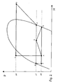
- zeigt ein Druck-Enthalpie-Diagramm zur Funktion der vorbekannten Vorrichtung aus Fig. 1.
- Fig. 3
- zeigt eine schematische Darstellung einer ersten Ausführungsform einer erfindungsgemäßen Vorrichtung.
- Fig.4
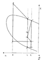
- zeigt ein Druck-Enthalpie-Diagramm zur Funktion der erfindungsgemäßen Vorrichtung aus Fig. 2.
- Fig. 5
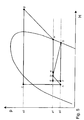
- zeigt ein Druck-Enthalpie-Diegramm der Vorrichtung aus Fig. 2 bei verringertem Abscheidegrad des Trennelements.
- Fig. 6
- zeigt eine schematische Darstellung einer zweiten Ausführungsform einer erfindungsgemäßen Vorrichtung.
- Bei der aus dem Stand der Technik bekannten Vorrichtung (Fig. 1) ist einem Verdichter oder Kompressor 1 ein Kondensator 2 nachgeordnet, welcher ein Kältemittel von einem expandierten Zustand A zunächst in einen komprimierten Zustand B und dann einen komprimierten und gekühlten Zustand C bei hohem Druck p2 überführt. Der Zustand C ist bei kondensierenden Kältemitteln flüssig; bei anderen Kältemitteln wie etwa Kohlendioxid kann er aber auch gasförmig sein. Auf den Kondensator folgt ein als Ejektor 3 ausgebildetes Expansionselement. Der Ejektor 3 hat einen als Düse 3a ausgeformten ersten Eingang für ein Kältemittel, in der das Kältemittel zunächst in einem stark gerichteten Strahl auf den Druck p0 (siehe Fig. 2, Punkt X) entspannt und dabei beschleunigt wird. Nachfolgend mischt sich dieser Gasstrahl mit Kältemittel aus einem in einem zweiten Eingang in den Ejektor mündenden Zweig 4a, der dem Auslaß eines einzigen Verdampfers 4 der Anordnung entspricht. Bei dem Ansaugen des Kältemittels aus dem Zweig 4a wird mechanische Arbeit des gerichteten schnellen Gasstrahls der Düse 3a genutzt. Die Expansion des gerichteten gemischten Strahls in einem Diffusor 3b des Ejektors 3 führt zu einem Druckanstieg des Gemisches auf den Druck p1 (siehe Punkt D in Fig. 2). Dieses Gemisch enthält flüssige und gasförmige Phase des Kältemittels; allgemein sind in den Zustandsdiagrammen nach Fig. 2, Fig. 4 und Fig. 5 Siedelinie und Taulinie eingezeichnet (jeweils linke bzw. rechte Hälfte der gebogenen Kurve), wobei sich zwischen der Siedelinie und der Taulinie der Naßdampfbereich befindet.
- Nach dem Verlassen des Ejektors 3 aus einem am Ende des Diffusors 3b angeordneten Ausgang tritt das Kältemittel in ein Trennelement bzw. einen Phasenseparator 7 ein, in dem der flüssige Anteil von dem gasförmigen Anteil getrennt wird. Dies ist in dem Zustandsdiagramm durch die beiden vom Punkt D isobar nach links und nach rechts laufenden punktierten Linien angedeutet. Die abgetrennte rein flüssige Phase entspricht dabei dem Punkt E und die abgetrennte rein gasförmige Phase entspricht dem Punkt A.
- Der gasförmige Anteil wird der Saugleitung des Verdichters 1 zugeführt. Der flüssige Teilstrom wird nach dem Trennelement 7 einer Drossel 6 (isenthalpe Entspannung von p1 nach p0 bzw. Punkt E zu Punkt F in Fig. 2) und dann dem Verdampfer 4 zugeführt,den er beim Zustand G verfässt.
- lm Unterschied zu dem Stand der Technik weist die erfindungsgemäße Vorrichtung der ersten Ausführungsform nach Fig. 3 lediglich ein stark vereinfachtes bzw. verkleinertes Trennelement 107 auf. Dieses ist zwar vorteilhaft hinsichtlich seiner Baugröße und Herstellungskosten, jedoch nicht ausreichend bezüglich einer vollständigen Separation von flüssiger Phase und Gasphase. Zwar wird ein erster Verdampfer 105, der kleiner als der einzige Verdampfer 4 nach dem Stand der Technik ist, ausschließlich mit flüssigem Kältemittel beschickt. Jedoch weist der andere Teil des Kältemittels ebenfalls noch flüssige Anteile auf und besteht nicht aus reiner Gasphase. In dem mit der Vorrichtung aus Fig. 3 korrespondierenden Zustandsdiagramm nach Fig. 4 äußert sich dies darin, daß der Punkt E auf der Siedelinie liegt, der Punkt H jedoch noch weit jenseits der Taulinie im Naßdampfbereich.
- Dieser Naßdampf gemäß Punkt H in Fig. 4 wird nunmehr einem zweiten Verdampfer 104 zugeführt. Dort wird durch Verdampfung der flüssigen Anteile und entsprechendem Wärmetausch mit zu klimatisierender Luft eine relevante Kühlleistung des Gesamtsystems erzeugt. Dem zweiten Verdampfer 104 ist ein Niederdrucksammler 8 nachgeordnet, dem wiederum die Saugseite des Verdichters 1 folgt. Der Niederdrucksammler stellt wie bei konventionellen Klimaanlagen sicher, daß der Verdichter keine Flüssigkeit ansaugen kann, was zu einer Beschädigung führen könnte.
- Aufgrund der unterschiedlichen Drücke ist die Verdampfungstemperatur des Kältemittels im ersten Verdampfer 105 niedriger als im zweiten Verdampfer 104. Zweckmäßig wird die zu klimatisierende Luft somit zunächst über den zweiten Verdampfer 104 und dann über den ersten Verdampfer 105 geleitet. Durch diese stufige Abkühlung der Luft ist eine weitere Verbesserung der Systemleistung bei gegebenen Baugrößen erzielbar, da der Wärmeübergang dem Verlauf der Lufttemperatur besser angepasst ist.
- In Abwandlung des Kältemittelzyklus aus Fig. 4 kann es gemäß Fig. 5 vorgesehen sein, daß auch das in dem ersten Sammler 105 bzw. seinem Expansionsorgan 6 zugeführte Kältemittel noch im Naßdampfbereich liegt (siehe Punkt E in Fig. 5). Dies stellt immer noch eine Verbesserung hinsichtlich Leistung und Gesamtwirkungsgrad gegenüber konventionellen Klimaanlagen dar, benötigt jedoch nur noch ein sehr kleines Trennelement 107. In weiterer Vereinfachung kann dann auch vollständig auf das Trennelement 107 verzichtet werden (Zusammenfall der Punkte E, D und H; nicht dargestettt). Auch bei einer solchen Ausführung werden der Wirkungsgrad und die Kälteleistung gegenüber konventionellen Anlagen erhöht, da weiterhin das Druckniveau der Saugleitung des Verdichters 1 erhöht ist bzw. mechanische Arbeit des Ejektors 3 zur Druckanhebung eines Kältemittelteils von p0 auf p1 genutzt wird. Es ist sogar denkbar, daß im Punkt E ein höherer Gasanteil vorliegt als im Punkt H, etwa, wenn der Druckverlust im zweiten Verdampfer 104 kritisch ist.
- Allgemein wird die Wirkung des Ejektorkreises verschlechtert, wenn im Punkt E und somit im Punkt F ein höherer Gasanteil bzw. geringerer Flüssigkeitsanteil vorliegt. Dies liegt darin begründet, daß auch das nicht zur Kälteleistung beitragende Gas durch den Ejektor 3 auf den höheren Druck p1 befördert werden muss. Bei der Gestaltung des Separators ist demnach ein optimaler Kompromiß zwischen Leistungs- und Wirkungsgradverbesserung uns apparativem Aufwand zu finden.
- Das zweite bevorzugte Ausührungsbeispiel gemäß Fig. 6 ist vorrangig zum Betrieb mit kondensierenden Kältemitteln geeignet und unterscheidet sich von dem ersten Ausführungsbeispiel wie folgt:
- Anstelle eines Niederdrucksammlers ist ein dem Kondensator nachgeordneter Hochdrucksammler 10 vorgesehen. Zwischen Hochdrucksammler 10 und Ejektor 3 ist zudem ein als steuerbares Ventil ausgebildetes Steuermittel 11 angeordnet. Eine Ventilöffnung des Steuermittels 11 erfolgt dabei in Abhängigkeit der Überhitzung in der Saugleitung des Verdichters 1. Hierzu ist ein Thermofühler 11a an der Saugleitung angeordnet. Die Funktion eines solchen Ventils ist analog zu einem thermostatischen Expansionsventil, wie es aus dem Stand der Technik allgemein bekannt ist. Die von der dort gemessenen Überhitzung abhängige Öffnung des Steuermittels 11 stellt somit sicher, daß das in die Saugleitung eintretende Kältemittel stets die notwendige Überhitzung aufweist und somit keine Flüssigkeit durch den Verdichter angesaugt werden kann. Die weiteren Komponenten entsprechen in Anordnung und Funktion dem ersten Ausführungsbeispiel.
Claims (16)
- Vorrichtung zur Luftkonditionierung für ein Kraftfahrzeug, umfassend
einen Verdichter (1) zur Kompression eines saugseitig zugeführten Kältemittels,
einen dem Verdichter (1) in Flußrichtung des Kältemittels nachgeordneten Kühler, insbesondere einen Kondensator (2),
ein dem Kühler (2) nachgeordnetes Expansionselement (3), wobei das Expansionselement (3) einen ersten Eingang (3a) zur Zuführung von Kältemittel aus dem Kühler (2) und zumindest einen zweiten Eingang (4a) zur Zuführung von Kältemittel in einem zum ersten Eingang (3a) unterschiedlichen, insbesondere hinsichtlich des Drucks verschiedenen Zustand aufweist und wobei das Expansionselement (3) einen Ausgang zum Auslaß eines Gemisches der beiden Eingänge aufweist, und
einen ersten Verdampfer (105), wobei zumindest ein Teil des aus dem Ausgang ausgelassenen Kältemittels dem ersten Verdampfer (105) zwecks Kühlung eines Luftstroms zuführbar ist und wobei das den ersten Verdampfer (105) verlassende Kältemittel zumindest teilweise dem zweiten Eingang (4a) des Expansionsmittels zuführbar ist,
dadurch gekennzeichnet,
daß ein Teil des aus dem Ausgang des Expansionsmittels (3) ausgelassenen Kältemittels einem zweiten Verdampfer (104) zuführbar ist, wobei das den zweiten Verdampfer (104) verlassende Kältemittel der Saugseite des Verdichters (1) zuführbar ist. - Vorrichtung nach Anspruch 1, dadurch gekennzeichnet, daß das Expansionselement (3) ein Ejektor ist, wobei das dem zweiten Eingang (4a) des Ejektors zugeführte Kältemittel vor dem Durchströmen des Ejektors (3) einen kleineren Druck aufweist als das den Ausgang des Ejektors verlassende Kältemittel.
- Vorrichtung nach einem der vorhergehenden Ansprüche, dadurch gekennzeichnet, daß dem Expansionselement (3) nachfolgend ein Trennelement (107) angeordnet ist, wobei in dem Trennelement (107) eine Separation und Aufteilung des Kältemittels in einen ersten Teil und einen zweiten Teil erFolgt, wobei der erste Teil einen höheren Flüssigkeitsanteil aufweist als der zweite Teil.
- Vorrichtung nach Anspruch 1 oder 2, dadurch gekennzeichnet, daß ein dem Expansionselement (3) nachfolgendes Trennelement zur zumindest teilweisen Auftrennung des Kältemittels nach flüssiger und gasförmiger Phase nicht vorhanden ist.
- Vorrichtung nach einem der vorhergehenden Ansprüche, dadurch gekennzeichnet, daß dem zweiten Verdampfer (104) nachfolgend und dem Verdichter (1) vorhergehend ein Sammler (8) angeordnet ist.
- Vorrichtung nach einem der vorhergehenden Ansprüche, dadurch gekennzeichnet, daß ein dem Kühler (2) nachgeordneter Hochdrucksammler (10) vorgesehen ist.
- Vorrichtung nach einem der vorhergehenden Ansprüche, dadurch gekennzeichnet, daß ein Steuermittel (11) zur Regelung eines Massenstroms des Expansionselements vorgesehen ist.
- Vorrichtung nach Anspruch 7, dadurch gekennzeichnet, daß das Steuermittel (11) ein dem Expansionselement (3) vorgelagertes, steuerbares Ventil (11, 11a) umfaßt.
- Vorrichtung nach Anspruch 7, dadurch gekennzeichnet, daß das Steuermittel integral mit dem Expansionselement (3) ausgebildet ist.
- Vorrichtung nach einem der vorhergehenden Ansprüche, dadurch gekennzeichnet, daß der erste Verdampfer (105) und der zweite Verdampfer (104) als bauliche Einheit ausgebildet sind.
- Vorrichtung nach einem der vorhergehenden Ansprüche, dadurch gekennzeichnet, daß ein Trennelement (107) als bauliche Einheit mit zumindest einem der Verdampfer (104, 105) ausgebildet ist.
- Vorrichtung nach einem der vorhergehenden Ansprüche, dadurch gekennzeichnet, daß das Expansionselement (3) als bauliche Einheit mit zumindest einem der Verdampfer (104, 105) ausgebildet ist.
- Vorrichtung nach einem der vorhergehenden Ansprüche, dadurch gekennzeichnet, daß zumindest einer der Verdampfer (104, 105) als Speicherverdampfer mit einem Kältespeicher ausgebildet ist.
- Vorrichtung nach einem der vorhergehenden Ansprüche, dadurch gekennzeichnet, daß das Kältemittel ein grundsätzlich unterkritisch betriebenes Kältemittel wie etwa R134a ist.
- Vorrichtung nach einem der Ansprüche 1 bis 13, dadurch gekennzeichnet, daß das Kältemittel R744 (Kohlendioxid) ist.
- Vorrichtung nach Anspruch 15, dadurch gekennzeichnet, daß ein innerer Wärmeübertrager zum Wärmeaustausch zwischen zwei Kältemittelströmen vorgesehen ist.
Applications Claiming Priority (1)
| Application Number | Priority Date | Filing Date | Title |
|---|---|---|---|
| DE102005021396A DE102005021396A1 (de) | 2005-05-04 | 2005-05-04 | Vorrichtung zur Luftkonditionierung für ein Kraftfahrzeug |
Publications (2)
| Publication Number | Publication Date |
|---|---|
| EP1719650A1 true EP1719650A1 (de) | 2006-11-08 |
| EP1719650B1 EP1719650B1 (de) | 2011-12-14 |
Family
ID=36677161
Family Applications (1)
| Application Number | Title | Priority Date | Filing Date |
|---|---|---|---|
| EP06008347A Expired - Lifetime EP1719650B1 (de) | 2005-05-04 | 2006-04-21 | Vorrichtung zur Luftkonditionierung für ein Kraftfahrzeug |
Country Status (3)
| Country | Link |
|---|---|
| EP (1) | EP1719650B1 (de) |
| AT (1) | ATE537021T1 (de) |
| DE (1) | DE102005021396A1 (de) |
Cited By (7)
| Publication number | Priority date | Publication date | Assignee | Title |
|---|---|---|---|---|
| EP2050601A3 (de) * | 2007-10-16 | 2009-05-06 | Behr GmbH & Co. KG | Vorrichtung zur Lufkonditionierung eines Kraftfahrzeuges |
| WO2009090059A1 (en) * | 2008-01-18 | 2009-07-23 | Valeo Klimasysteme Gmbh | Refrigerant circuit and method for operating a refrigerant circuit |
| CN100529589C (zh) * | 2007-10-30 | 2009-08-19 | 西安交通大学 | 一种带喷射器的小型节流低温制冷机循环系统 |
| US7823401B2 (en) | 2006-10-27 | 2010-11-02 | Denso Corporation | Refrigerant cycle device |
| WO2015029394A1 (ja) * | 2013-08-29 | 2015-03-05 | 株式会社デンソー | エジェクタ式冷凍サイクルおよびエジェクタ |
| US10823461B2 (en) | 2015-05-13 | 2020-11-03 | Carrier Corporation | Ejector refrigeration circuit |
| CN115046325A (zh) * | 2022-05-09 | 2022-09-13 | 北京航空航天大学 | 一种适用于空气液化的喷射器式分级制冷循环系统 |
Families Citing this family (13)
| Publication number | Priority date | Publication date | Assignee | Title |
|---|---|---|---|---|
| DE102006042789A1 (de) * | 2006-09-08 | 2008-03-27 | Behr Gmbh & Co. Kg | Klimaanalge mit Kältespeicher und Verfahren zum Betreiben einer solchen |
| JP5050563B2 (ja) * | 2007-02-27 | 2012-10-17 | 株式会社デンソー | エジェクタ及びエジェクタ式冷凍サイクル用ユニット |
| JP4715797B2 (ja) * | 2007-04-03 | 2011-07-06 | 株式会社デンソー | エジェクタ式冷凍サイクル |
| DE102007025225A1 (de) * | 2007-05-31 | 2008-12-04 | Valeo Klimasysteme Gmbh | Ejektorpumpe |
| DE102007035110A1 (de) * | 2007-07-20 | 2009-01-22 | Visteon Global Technologies Inc., Van Buren | Klimaanlage für Kraftfahrzeuge und Verfahren zu ihrem Betrieb |
| DE102008059898A1 (de) | 2008-12-02 | 2010-06-10 | Behr Gmbh & Co. Kg | Ejektor für einen Kältekreis und Herstellungsverfahren |
| DE102009050886A1 (de) * | 2009-10-27 | 2011-04-28 | Behr Gmbh & Co. Kg | Verdampfermodul |
| DE102010031409B4 (de) | 2010-07-15 | 2018-12-27 | Mahle International Gmbh | Treibdüse für ein mit siedendem Fluid angetriebenes Expansionselement |
| DE102010031388A1 (de) | 2010-07-15 | 2012-01-19 | Behr Gmbh & Co. Kg | Expansionselement für ein System zur Luftkonditionierung für ein Kraftfahrzeug |
| DE102010031391A1 (de) | 2010-07-15 | 2012-01-19 | Behr Gmbh & Co. Kg | Verdampfermodul |
| EP2519787B1 (de) * | 2010-07-23 | 2014-12-03 | Carrier Corporation | Ejektorzyklus |
| DE102010056414A1 (de) | 2010-12-23 | 2012-06-28 | Volkswagen Ag | Klimaanlage mit Kompressions- und Sorptionskälteanlagenkreislauf |
| US10113776B2 (en) | 2016-07-20 | 2018-10-30 | Haier Us Appliance Solutions, Inc. | Packaged terminal air conditioner unit |
Citations (5)
| Publication number | Priority date | Publication date | Assignee | Title |
|---|---|---|---|---|
| US1944472A (en) * | 1930-09-22 | 1934-01-23 | Vilter Mfg Co | Art of refrigeration |
| JPH06137695A (ja) * | 1992-10-22 | 1994-05-20 | Nippondenso Co Ltd | 冷凍サイクル |
| DE10156882A1 (de) * | 2001-01-05 | 2002-08-29 | Behr Gmbh & Co | Klimaanlage für ein Kraftfahrzeug |
| JP2004198045A (ja) * | 2002-12-19 | 2004-07-15 | Denso Corp | 蒸気圧縮式冷凍機 |
| DE102004029510A1 (de) * | 2003-06-19 | 2005-01-13 | Denso Corp., Kariya | Ejektor-Kreislauf |
Family Cites Families (7)
| Publication number | Priority date | Publication date | Assignee | Title |
|---|---|---|---|---|
| US1840955A (en) * | 1929-01-14 | 1932-01-12 | Baker Ice Machine Co Inc | Refrigeration system |
| DE3721388C1 (de) * | 1987-06-29 | 1988-12-08 | Sueddeutsche Kuehler Behr | Vorrichtung zur Klimatisierung des Innenraums von Personenkraftwagen |
| DE4036854C1 (de) * | 1990-11-19 | 1992-05-21 | Thermal-Werke, Waerme-, Kaelte-, Klimatechnik Gmbh, 6832 Hockenheim, De | |
| ATE187398T1 (de) * | 1994-01-12 | 1999-12-15 | Abb Daimler Benz Transp | Kompaktklimagerät |
| DE19645178C2 (de) * | 1996-11-02 | 1999-12-16 | Webasto Thermosysteme Gmbh | Vorrichtung zur Kühlung eines Fahrzeuginnenraumes |
| JP4110895B2 (ja) * | 2002-09-09 | 2008-07-02 | 株式会社デンソー | 空調装置および車両用空調装置 |
| DE10338824A1 (de) * | 2003-08-21 | 2005-03-24 | Behr Gmbh & Co. Kg | Klimaanlage |
-
2005
- 2005-05-04 DE DE102005021396A patent/DE102005021396A1/de not_active Withdrawn
-
2006
- 2006-04-21 EP EP06008347A patent/EP1719650B1/de not_active Expired - Lifetime
- 2006-04-21 AT AT06008347T patent/ATE537021T1/de active
Patent Citations (5)
| Publication number | Priority date | Publication date | Assignee | Title |
|---|---|---|---|---|
| US1944472A (en) * | 1930-09-22 | 1934-01-23 | Vilter Mfg Co | Art of refrigeration |
| JPH06137695A (ja) * | 1992-10-22 | 1994-05-20 | Nippondenso Co Ltd | 冷凍サイクル |
| DE10156882A1 (de) * | 2001-01-05 | 2002-08-29 | Behr Gmbh & Co | Klimaanlage für ein Kraftfahrzeug |
| JP2004198045A (ja) * | 2002-12-19 | 2004-07-15 | Denso Corp | 蒸気圧縮式冷凍機 |
| DE102004029510A1 (de) * | 2003-06-19 | 2005-01-13 | Denso Corp., Kariya | Ejektor-Kreislauf |
Non-Patent Citations (2)
| Title |
|---|
| PATENT ABSTRACTS OF JAPAN vol. 018, no. 446 (M - 1659) 19 August 1994 (1994-08-19) * |
| PATENT ABSTRACTS OF JAPAN vol. 2003, no. 12 5 December 2003 (2003-12-05) * |
Cited By (12)
| Publication number | Priority date | Publication date | Assignee | Title |
|---|---|---|---|---|
| US7823401B2 (en) | 2006-10-27 | 2010-11-02 | Denso Corporation | Refrigerant cycle device |
| EP2050601A3 (de) * | 2007-10-16 | 2009-05-06 | Behr GmbH & Co. KG | Vorrichtung zur Lufkonditionierung eines Kraftfahrzeuges |
| EP2223815A1 (de) * | 2007-10-16 | 2010-09-01 | Behr GmbH & Co. KG | Vorrichtung zur Luftkonditionierung eines Kraftfahrzeuges |
| EP2230113A1 (de) * | 2007-10-16 | 2010-09-22 | Behr GmbH & Co. KG | Vorrichtung zur Luftkonditionierung eines Kraftfahrzeuges |
| CN100529589C (zh) * | 2007-10-30 | 2009-08-19 | 西安交通大学 | 一种带喷射器的小型节流低温制冷机循环系统 |
| WO2009090059A1 (en) * | 2008-01-18 | 2009-07-23 | Valeo Klimasysteme Gmbh | Refrigerant circuit and method for operating a refrigerant circuit |
| WO2015029394A1 (ja) * | 2013-08-29 | 2015-03-05 | 株式会社デンソー | エジェクタ式冷凍サイクルおよびエジェクタ |
| JP2015045477A (ja) * | 2013-08-29 | 2015-03-12 | 株式会社デンソー | エジェクタ式冷凍サイクルおよびエジェクタ |
| US10465957B2 (en) | 2013-08-29 | 2019-11-05 | Denso Corporation | Ejector-type refrigeration cycle, and ejector |
| DE112014003905B4 (de) | 2013-08-29 | 2022-02-24 | Denso Corporation | Ejektorkältekreislauf und Ejektor |
| US10823461B2 (en) | 2015-05-13 | 2020-11-03 | Carrier Corporation | Ejector refrigeration circuit |
| CN115046325A (zh) * | 2022-05-09 | 2022-09-13 | 北京航空航天大学 | 一种适用于空气液化的喷射器式分级制冷循环系统 |
Also Published As
| Publication number | Publication date |
|---|---|
| ATE537021T1 (de) | 2011-12-15 |
| DE102005021396A1 (de) | 2006-11-09 |
| EP1719650B1 (de) | 2011-12-14 |
Similar Documents
| Publication | Publication Date | Title |
|---|---|---|
| EP1719650B1 (de) | Vorrichtung zur Luftkonditionierung für ein Kraftfahrzeug | |
| DE102006036549B4 (de) | Ejektorpumpenkreis | |
| DE60218087T2 (de) | Strahlkreislaufanordnung | |
| DE102006038061B4 (de) | Kühlkreislaufausbildung mit Ejektor | |
| DE10330608A1 (de) | Ejektorkreislauf | |
| EP0701096A2 (de) | Verfahren zum Betreiben einer Kälteerzeugungsanlage für das Klimatisieren von Fahrzeugen und eine Kälteerzeugungsanlage zur Durchführung desselben | |
| DE112015002568T5 (de) | Ejektor-Kühlkreislauf | |
| EP0487002B1 (de) | Vorrichtung zur Klimatisierung des Innenraums von Kraftfahrzeugen | |
| EP4186725B1 (de) | Klimatisierungsanordnung mit geregeltem ejektor | |
| DE102020119813A1 (de) | Kältemittelkreislauf einer kombinierten Kälteanlage und Wärmepumpe mit integriertem Dampfinjektionskreislauf | |
| DE102008050858A1 (de) | Kältekreislaufvorrichtung | |
| DE69513765T2 (de) | Kälteanlage | |
| WO2022106119A1 (de) | Kühleinrichtung für ein fahrzeug | |
| DE102006035784B4 (de) | Kälteanlage für transkritischen Betrieb mit Economiser und Niederdruck-Sammler | |
| EP2050601B1 (de) | Vorrichtung zur Lufkonditionierung eines Kraftfahrzeuges | |
| DE102008005076A1 (de) | Kältemittelkreis und Verfahren zum Betreiben eines Kältemittelkreises | |
| DE19708428C2 (de) | Kälteanlage | |
| DE29500781U1 (de) | Vorrichtung zum Kühlen von Gasen | |
| DE10343820A1 (de) | Dampfverdichtungskältemittelkreislauf | |
| DE112017005948T5 (de) | Klimatisierungsvorrichtung | |
| DE102020201455A1 (de) | System sowie Verfahren zur Klimatisierung eines Fahrzeuginnenraums und gleichzeitigen Kühlung einer Fahrzeugbatterie für ein elektrisches Fahrzeug | |
| DE102011012644A1 (de) | Kälteanlage | |
| DE102008011255A1 (de) | Ejektorzyklus mit einphasigem Strahl | |
| WO2004055454A1 (de) | Kältemittelkreislauf für eine kfz-klimaanlage | |
| WO2019015891A1 (de) | Kälteanlage eines fahrzeugs mit einem kältemittelkreislauf |
Legal Events
| Date | Code | Title | Description |
|---|---|---|---|
| PUAI | Public reference made under article 153(3) epc to a published international application that has entered the european phase |
Free format text: ORIGINAL CODE: 0009012 |
|
| AK | Designated contracting states |
Kind code of ref document: A1 Designated state(s): AT BE BG CH CY CZ DE DK EE ES FI FR GB GR HU IE IS IT LI LT LU LV MC NL PL PT RO SE SI SK TR |
|
| AX | Request for extension of the european patent |
Extension state: AL BA HR MK YU |
|
| 17P | Request for examination filed |
Effective date: 20070508 |
|
| AKX | Designation fees paid |
Designated state(s): AT BE BG CH CY CZ DE DK EE ES FI FR GB GR HU IE IS IT LI LT LU LV MC NL PL PT RO SE SI SK TR |
|
| 17Q | First examination report despatched |
Effective date: 20070621 |
|
| GRAP | Despatch of communication of intention to grant a patent |
Free format text: ORIGINAL CODE: EPIDOSNIGR1 |
|
| GRAS | Grant fee paid |
Free format text: ORIGINAL CODE: EPIDOSNIGR3 |
|
| GRAA | (expected) grant |
Free format text: ORIGINAL CODE: 0009210 |
|
| AK | Designated contracting states |
Kind code of ref document: B1 Designated state(s): AT BE BG CH CY CZ DE DK EE ES FI FR GB GR HU IE IS IT LI LT LU LV MC NL PL PT RO SE SI SK TR |
|
| REG | Reference to a national code |
Ref country code: GB Ref legal event code: FG4D Free format text: NOT ENGLISH |
|
| REG | Reference to a national code |
Ref country code: CH Ref legal event code: EP |
|
| REG | Reference to a national code |
Ref country code: IE Ref legal event code: FG4D |
|
| REG | Reference to a national code |
Ref country code: DE Ref legal event code: R096 Ref document number: 502006010695 Country of ref document: DE Effective date: 20120216 |
|
| REG | Reference to a national code |
Ref country code: NL Ref legal event code: VDEP Effective date: 20111214 |
|
| PG25 | Lapsed in a contracting state [announced via postgrant information from national office to epo] |
Ref country code: LT Free format text: LAPSE BECAUSE OF FAILURE TO SUBMIT A TRANSLATION OF THE DESCRIPTION OR TO PAY THE FEE WITHIN THE PRESCRIBED TIME-LIMIT Effective date: 20111214 |
|
| LTIE | Lt: invalidation of european patent or patent extension |
Effective date: 20111214 |
|
| PG25 | Lapsed in a contracting state [announced via postgrant information from national office to epo] |
Ref country code: NL Free format text: LAPSE BECAUSE OF FAILURE TO SUBMIT A TRANSLATION OF THE DESCRIPTION OR TO PAY THE FEE WITHIN THE PRESCRIBED TIME-LIMIT Effective date: 20111214 Ref country code: SI Free format text: LAPSE BECAUSE OF FAILURE TO SUBMIT A TRANSLATION OF THE DESCRIPTION OR TO PAY THE FEE WITHIN THE PRESCRIBED TIME-LIMIT Effective date: 20111214 Ref country code: LV Free format text: LAPSE BECAUSE OF FAILURE TO SUBMIT A TRANSLATION OF THE DESCRIPTION OR TO PAY THE FEE WITHIN THE PRESCRIBED TIME-LIMIT Effective date: 20111214 Ref country code: GR Free format text: LAPSE BECAUSE OF FAILURE TO SUBMIT A TRANSLATION OF THE DESCRIPTION OR TO PAY THE FEE WITHIN THE PRESCRIBED TIME-LIMIT Effective date: 20120315 Ref country code: SE Free format text: LAPSE BECAUSE OF FAILURE TO SUBMIT A TRANSLATION OF THE DESCRIPTION OR TO PAY THE FEE WITHIN THE PRESCRIBED TIME-LIMIT Effective date: 20111214 |
|
| PG25 | Lapsed in a contracting state [announced via postgrant information from national office to epo] |
Ref country code: CY Free format text: LAPSE BECAUSE OF FAILURE TO SUBMIT A TRANSLATION OF THE DESCRIPTION OR TO PAY THE FEE WITHIN THE PRESCRIBED TIME-LIMIT Effective date: 20111214 |
|
| REG | Reference to a national code |
Ref country code: IE Ref legal event code: FD4D |
|
| PG25 | Lapsed in a contracting state [announced via postgrant information from national office to epo] |
Ref country code: CZ Free format text: LAPSE BECAUSE OF FAILURE TO SUBMIT A TRANSLATION OF THE DESCRIPTION OR TO PAY THE FEE WITHIN THE PRESCRIBED TIME-LIMIT Effective date: 20111214 Ref country code: BG Free format text: LAPSE BECAUSE OF FAILURE TO SUBMIT A TRANSLATION OF THE DESCRIPTION OR TO PAY THE FEE WITHIN THE PRESCRIBED TIME-LIMIT Effective date: 20120314 Ref country code: SK Free format text: LAPSE BECAUSE OF FAILURE TO SUBMIT A TRANSLATION OF THE DESCRIPTION OR TO PAY THE FEE WITHIN THE PRESCRIBED TIME-LIMIT Effective date: 20111214 Ref country code: EE Free format text: LAPSE BECAUSE OF FAILURE TO SUBMIT A TRANSLATION OF THE DESCRIPTION OR TO PAY THE FEE WITHIN THE PRESCRIBED TIME-LIMIT Effective date: 20111214 Ref country code: IS Free format text: LAPSE BECAUSE OF FAILURE TO SUBMIT A TRANSLATION OF THE DESCRIPTION OR TO PAY THE FEE WITHIN THE PRESCRIBED TIME-LIMIT Effective date: 20120414 Ref country code: IE Free format text: LAPSE BECAUSE OF FAILURE TO SUBMIT A TRANSLATION OF THE DESCRIPTION OR TO PAY THE FEE WITHIN THE PRESCRIBED TIME-LIMIT Effective date: 20111214 |
|
| PG25 | Lapsed in a contracting state [announced via postgrant information from national office to epo] |
Ref country code: PL Free format text: LAPSE BECAUSE OF FAILURE TO SUBMIT A TRANSLATION OF THE DESCRIPTION OR TO PAY THE FEE WITHIN THE PRESCRIBED TIME-LIMIT Effective date: 20111214 Ref country code: PT Free format text: LAPSE BECAUSE OF FAILURE TO SUBMIT A TRANSLATION OF THE DESCRIPTION OR TO PAY THE FEE WITHIN THE PRESCRIBED TIME-LIMIT Effective date: 20120416 Ref country code: RO Free format text: LAPSE BECAUSE OF FAILURE TO SUBMIT A TRANSLATION OF THE DESCRIPTION OR TO PAY THE FEE WITHIN THE PRESCRIBED TIME-LIMIT Effective date: 20111214 |
|
| PLBE | No opposition filed within time limit |
Free format text: ORIGINAL CODE: 0009261 |
|
| STAA | Information on the status of an ep patent application or granted ep patent |
Free format text: STATUS: NO OPPOSITION FILED WITHIN TIME LIMIT |
|
| BERE | Be: lapsed |
Owner name: BEHR G.M.B.H. & CO. KG Effective date: 20120430 |
|
| PG25 | Lapsed in a contracting state [announced via postgrant information from national office to epo] |
Ref country code: DK Free format text: LAPSE BECAUSE OF FAILURE TO SUBMIT A TRANSLATION OF THE DESCRIPTION OR TO PAY THE FEE WITHIN THE PRESCRIBED TIME-LIMIT Effective date: 20111214 |
|
| 26N | No opposition filed |
Effective date: 20120917 |
|
| PG25 | Lapsed in a contracting state [announced via postgrant information from national office to epo] |
Ref country code: MC Free format text: LAPSE BECAUSE OF NON-PAYMENT OF DUE FEES Effective date: 20120430 Ref country code: IT Free format text: LAPSE BECAUSE OF FAILURE TO SUBMIT A TRANSLATION OF THE DESCRIPTION OR TO PAY THE FEE WITHIN THE PRESCRIBED TIME-LIMIT Effective date: 20111214 |
|
| REG | Reference to a national code |
Ref country code: CH Ref legal event code: PL |
|
| REG | Reference to a national code |
Ref country code: DE Ref legal event code: R097 Ref document number: 502006010695 Country of ref document: DE Effective date: 20120917 |
|
| PG25 | Lapsed in a contracting state [announced via postgrant information from national office to epo] |
Ref country code: LI Free format text: LAPSE BECAUSE OF NON-PAYMENT OF DUE FEES Effective date: 20120430 Ref country code: CH Free format text: LAPSE BECAUSE OF NON-PAYMENT OF DUE FEES Effective date: 20120430 Ref country code: BE Free format text: LAPSE BECAUSE OF NON-PAYMENT OF DUE FEES Effective date: 20120430 |
|
| PG25 | Lapsed in a contracting state [announced via postgrant information from national office to epo] |
Ref country code: ES Free format text: LAPSE BECAUSE OF FAILURE TO SUBMIT A TRANSLATION OF THE DESCRIPTION OR TO PAY THE FEE WITHIN THE PRESCRIBED TIME-LIMIT Effective date: 20120325 |
|
| REG | Reference to a national code |
Ref country code: AT Ref legal event code: MM01 Ref document number: 537021 Country of ref document: AT Kind code of ref document: T Effective date: 20120421 |
|
| PG25 | Lapsed in a contracting state [announced via postgrant information from national office to epo] |
Ref country code: FI Free format text: LAPSE BECAUSE OF FAILURE TO SUBMIT A TRANSLATION OF THE DESCRIPTION OR TO PAY THE FEE WITHIN THE PRESCRIBED TIME-LIMIT Effective date: 20111214 |
|
| PG25 | Lapsed in a contracting state [announced via postgrant information from national office to epo] |
Ref country code: AT Free format text: LAPSE BECAUSE OF NON-PAYMENT OF DUE FEES Effective date: 20120421 |
|
| PG25 | Lapsed in a contracting state [announced via postgrant information from national office to epo] |
Ref country code: TR Free format text: LAPSE BECAUSE OF FAILURE TO SUBMIT A TRANSLATION OF THE DESCRIPTION OR TO PAY THE FEE WITHIN THE PRESCRIBED TIME-LIMIT Effective date: 20111214 |
|
| PG25 | Lapsed in a contracting state [announced via postgrant information from national office to epo] |
Ref country code: LU Free format text: LAPSE BECAUSE OF NON-PAYMENT OF DUE FEES Effective date: 20120421 |
|
| PG25 | Lapsed in a contracting state [announced via postgrant information from national office to epo] |
Ref country code: HU Free format text: LAPSE BECAUSE OF FAILURE TO SUBMIT A TRANSLATION OF THE DESCRIPTION OR TO PAY THE FEE WITHIN THE PRESCRIBED TIME-LIMIT Effective date: 20060421 |
|
| REG | Reference to a national code |
Ref country code: DE Ref legal event code: R082 Ref document number: 502006010695 Country of ref document: DE Representative=s name: GRAUEL, ANDREAS, DIPL.-PHYS. DR. RER. NAT., DE |
|
| REG | Reference to a national code |
Ref country code: DE Ref legal event code: R081 Ref document number: 502006010695 Country of ref document: DE Owner name: MAHLE INTERNATIONAL GMBH, DE Free format text: FORMER OWNER: BEHR GMBH & CO. KG, 70469 STUTTGART, DE Effective date: 20111223 Ref country code: DE Ref legal event code: R082 Ref document number: 502006010695 Country of ref document: DE Representative=s name: GRAUEL, ANDREAS, DIPL.-PHYS. DR. RER. NAT., DE Effective date: 20150311 Ref country code: DE Ref legal event code: R081 Ref document number: 502006010695 Country of ref document: DE Owner name: MAHLE INTERNATIONAL GMBH, DE Free format text: FORMER OWNER: BEHR GMBH & CO. KG, 70469 STUTTGART, DE Effective date: 20150311 |
|
| REG | Reference to a national code |
Ref country code: FR Ref legal event code: PLFP Year of fee payment: 11 |
|
| REG | Reference to a national code |
Ref country code: FR Ref legal event code: PLFP Year of fee payment: 12 |
|
| REG | Reference to a national code |
Ref country code: FR Ref legal event code: PLFP Year of fee payment: 13 |
|
| PGFP | Annual fee paid to national office [announced via postgrant information from national office to epo] |
Ref country code: DE Payment date: 20190619 Year of fee payment: 14 |
|
| PGFP | Annual fee paid to national office [announced via postgrant information from national office to epo] |
Ref country code: FR Payment date: 20190423 Year of fee payment: 14 |
|
| PGFP | Annual fee paid to national office [announced via postgrant information from national office to epo] |
Ref country code: GB Payment date: 20190423 Year of fee payment: 14 |
|
| REG | Reference to a national code |
Ref country code: DE Ref legal event code: R119 Ref document number: 502006010695 Country of ref document: DE |
|
| PG25 | Lapsed in a contracting state [announced via postgrant information from national office to epo] |
Ref country code: DE Free format text: LAPSE BECAUSE OF NON-PAYMENT OF DUE FEES Effective date: 20201103 Ref country code: FR Free format text: LAPSE BECAUSE OF NON-PAYMENT OF DUE FEES Effective date: 20200430 |
|
| GBPC | Gb: european patent ceased through non-payment of renewal fee |
Effective date: 20200421 |
|
| PG25 | Lapsed in a contracting state [announced via postgrant information from national office to epo] |
Ref country code: GB Free format text: LAPSE BECAUSE OF NON-PAYMENT OF DUE FEES Effective date: 20200421 |