EP1715313B1 - Lichtkontrasttaster zur Erkennung von Marken - Google Patents
Lichtkontrasttaster zur Erkennung von Marken Download PDFInfo
- Publication number
- EP1715313B1 EP1715313B1 EP06006461A EP06006461A EP1715313B1 EP 1715313 B1 EP1715313 B1 EP 1715313B1 EP 06006461 A EP06006461 A EP 06006461A EP 06006461 A EP06006461 A EP 06006461A EP 1715313 B1 EP1715313 B1 EP 1715313B1
- Authority
- EP
- European Patent Office
- Prior art keywords
- light
- light guide
- contrast scanner
- chamber
- scanner
- Prior art date
- Legal status (The legal status is an assumption and is not a legal conclusion. Google has not performed a legal analysis and makes no representation as to the accuracy of the status listed.)
- Expired - Lifetime
Links
Images


Classifications
-
- G—PHYSICS
- G01—MEASURING; TESTING
- G01J—MEASUREMENT OF INTENSITY, VELOCITY, SPECTRAL CONTENT, POLARISATION, PHASE OR PULSE CHARACTERISTICS OF INFRARED, VISIBLE OR ULTRAVIOLET LIGHT; COLORIMETRY; RADIATION PYROMETRY
- G01J3/00—Spectrometry; Spectrophotometry; Monochromators; Measuring colours
- G01J3/46—Measurement of colour; Colour measuring devices, e.g. colorimeters
Definitions
- the invention relates to a light contrast sensor for detecting marks and / or colors according to the preamble of claim 1.
- the light contrast sensor includes a light transmitter for emitting transmitted light through a transmitting optics, a light receiver for receiving reflected or remitted transmitted light and a control and evaluation circuit.
- the light transmitter is designed to emit transmitted light of several different test wavelength ranges. The different colors are combined or mixed to form a common transmission beam by means of a cylindrical lens.
- the light contrast sensor requires a multi-part and complex transmission optics for spatially overlapping imaging of the transmitted light for several test wavelength ranges, so that the overlapping area forms a common monitoring area of the light contrast sensor.
- the cylindrical lens is a part of the transmission optics, by which the transmitted light of a transmitting element can be ultimately imaged on the surveillance area as a cross-section of longitudinally oval-shaped transmission beams. Through the cylindrical lens colors are mixed only insufficient. Elaborate is the assembly, the production and alignment of the individual parts of the transmission optics to each other. As a result, the production of such a light contrast sensor is costly.
- the multi-part transmission optics and in particular the cylindrical lens require by their size and the necessary distances a lot of space. Especially with this type of sensors, it is desirable to realize particularly small designs.
- Another light contrast button for detecting colors is from the EP 0 994 334 A2 known.
- the object of the invention is to provide an improved light contrast sensor for detecting marks and / or colors.
- the object is achieved according to the invention according to claim 1, characterized in that the light contrast sensor for detecting marks and / or colors with a light transmitter with spatially adjacent transmitting elements, in particular light emitting diodes for emitting transmitted light of several different wavelength ranges, in particular in the red, green and blue wavelength range of light, is trained.
- the light contrast button includes a transmission optics.
- a light receiver for receiving reflected or remitted transmitted light is provided in the light contrast button a control and evaluation circuit is mounted. At least one means for mixing different color components of the transmitted light is present, wherein the means is formed by a light guide and the light emitter and the light guide are arranged in a common tube.
- the advantage of this inventive design of the light contrast sensor is that the mixing of the different color components is accomplished with the very inexpensive and optimal for this task optical fiber.
- the light guide is characterized by the property of passing light through total reflection, ideal for the solution to mix different color components in a small space.
- Especially the small design is a great advantage for this type of sensors.
- the light emitter and the light guide are arranged in a common tube, this provides a common basis for the mounting of the Lichtsen-ders and the light guide.
- the reference dimensions of the arrangement are determined via mounting surfaces of the components and corresponding stop surfaces on the tube. In this way, the components light emitter and light guide need not be aligned separately.
- the length of the light guide is advantageously at least 3.5 times a transverse dimension of the light guide.
- the light guide is advantageously formed on the light emitter facing coupling surface as a lens.
- the lens is formed integrally with the light guide.
- the light guide advantageously has a rectangular cross-section.
- the rectangular cross section is particularly adapted to the arrangement of the transmitting elements.
- the rectangular shape also offers the advantage of a very compact design of the light guide.
- the length of the light guide is at least 7 times the shorter side of the rectangular cross section.
- the light guide consists of plastic transparent to the transmitted light. Through the use of plastic, the light guide is particularly inexpensive to produce. In particular, suitable manufacturing methods such as the injection molding process allow the production of the light guide at low cost.
- the light guide off Plastic is easy to work with and assemble. Risk of breakage, eg with glass, does not exist. Due to the low weight of the light guide, this is particularly suitable for high vibration and shock requirements of the light contrast sensor.
- the light guide has on its light exit side on a mounting plate, which is advantageously integrally connected to the light guide.
- the mounting plate of the light guide can be produced together with the light guide in one step.
- the mounting plate of the light guide is thus accurately aligned with the light guide. This allows a particularly simple installation of the light guide.
- the mounting plate is advantageously connected only at the corners of the rectangular cross-section with the light guide and arranged perpendicular to the light guide. Due to the exclusive connection of the mounting plate at the corners of the light guide the property of the total reflection of the light guide is minimally affected.
- the vertical arrangement of the mounting plate to the light guide allows a particularly simple installation of the light guide, if, for. the mounting plate is mounted against a stop.
- the tube advantageously has a first chamber, a second chamber and a tubular connection of the two chambers.
- the tubular connection of the light guide is arranged and the coupling surface of the light guide is arranged in the direction of the first chamber in which the light emitter is arranged.
- the arrangement of the chambers and the tubular connection allows a protected modular construction of the components on and in the tube.
- a diaphragm In the second chamber and on the light exit side of the light guide, a diaphragm is arranged.
- the diaphragm is advantageously also mounted in the tube and is thereby aligned with the other components in particular to the light exit side of the light guide.
- the aperture advantageously has a latching mechanism for mounting in the second chamber of the tube.
- the latching mechanism is integrally integrated in the panel.
- the aperture can thus be produced very inexpensively and be mounted.
- the second chamber has an insertion opening for mounting the panel in order to insert the panel into the tube. Through the insertion in the tube, the aperture is positioned exactly and is aligned without further assembly steps.
- the latch mechanism holds the bezel in the correct position. When exposed to shock or vibration, the bezel can not move from its intended position.
- the aperture is preferably formed of metal.
- the aperture can be formed very precisely.
- the aperture can also be made very thin and thus save space.
- the mounting plate of the light guide is kept positioned in the tube by means of the inserted aperture.
- a Montagenplatten technique is provided with wedge-shaped sides for adjusting the mounting plate.
- the light transmitter is arranged on a printed circuit board, and the first chamber of the tube has a printed circuit board receptacle.
- the tube has a slot for receiving a nose of the circuit board and a wedge snap closure for receiving a side facing away from the nose of the circuit board, which is formed as a blunt tip.
- the transmission elements applied to the printed circuit board are aligned and mounted exactly to the lens of the optical waveguide which projects through the tubular connection into the first chamber.
- the circuit board receptacle in addition to two adjacent stop sides, against which the circuit board is held by the wedge snap in tension in position.
- the abutment sides are formed by chamber walls of the first chamber.
- the circuit board is advantageously equipped on both sides with transmitting elements. As a result, different mounting variants of the circuit board can be realized with only one circuit board.
- the second component side can be equipped with alternative light emitting diodes with other ratios. This not only increases the variety of variants in the simplest way, but it can also be resorted to without design changes to other diodes in delivery bottlenecks of the light emitting diodes.
- the tube has an opening for a monitor receiving element, in particular a monitor diode.
- a monitor diode By means of this monitor diode, the wavelength and the intensity as well as the switching behavior of the light emitting diodes can be monitored or checked, for example by observing stray light of the actual transmitted light.
- the intensity of the transmitting elements can be readjusted via the control circuit.
- scattered light can be viewed directly from the transmitting elements or scattered light on the mounting plate of the light guide.
- the tube has alignment pins for aligned recording in a housing of the light contrast button.
- the tube with the optical components is advantageously aligned directly on the housing of the light contrast scanner.
- the alignment pins of the tube and pin holes of the housing are accurate manufactured, which requires the optical system and guarantees proper operation.
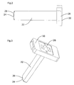
- FIG. 1 shows a schematic representation of a light contrast button 1.
- the light contrast button is housed in a housing 3.
- a light emitter 2 and a light receiver 12 is arranged in the housing 3.
- the light transmitter 2 and a light receiver 12 are connected to a control and evaluation circuit 16.
- the light transmitter 2 is arranged in a tube 32.
- a light guide 22, a diaphragm 40 and a transmission optical system 10 is further arranged.
- the transmitted from the light emitter 2 transmitted light strikes the light guide and passes to the aperture 40 and the transmitting optics 10 on a beam splitter 82.
- the beam splitter 82 divides the transmitted light in a proportion in the direction of a first objective lens 80 and in a proportion in the direction of a second objective lens 80 'up.
- the light contrast sensor 1 can selectively emit or receive the transmitted light or also the received light in two different directions.
- One of the two openings is closed during operation of the light contrast pushbutton 1 by a closure cap.
- the user is thus able to flexibly use one of the two light exit sides for his application.
- the light transmitter 2 is designed in such a way that sufficient light is emitted for color recognition via each of the objective optics 80 and 80 '.
- the transmitted light 8 reaches a contrast mark or a color mark.
- the light is reflected by this mark and hits the objective optics 80 or 80 'again.
- Reflected light 14 impinges on the beam splitter 82 and then on a receiving optical system 84.
- the receiving optical system 84 focuses the received light 14 onto the light receiver 12.
- the signal of the light receiver 12 is evaluated and, for example, generates a switching signal depending on the detected color.
- the light guide 22 is shown in a side view.
- the light guide 22 has a coupling-in surface 24.
- the coupling surface 24 is formed as a lens 26.
- the lens 26 is integrally connected to the light guide 22. This results in no additional optical interface between lens 26 and light guide 22.
- the light guide 22 is elongated with a Length to cross-sectional dimension ratio of at least 3.5.
- the light guide 22 has on the opposite side of the coupling surface 24, on a light exit side 28 a mounting plate 30.
- the mounting plate 30 is arranged at right angles to the light guide 22.
- the light guide 22 is shown in a perspective view to illustrate the constructive expression of the light guide 22.
- the elongated light guide 22 is formed with a rectangular cross-section. As a result of this rectangular shape, the light of transmitting elements arranged side by side in a row can reach the light guide 22 particularly well via the correspondingly pronounced lens 26.
- the various color components of the transmitted light are mixed by multiple total reflection of the light along the length of the light guide 22.
- the light guide 22 is connected to maintain the total reflection properties of the light guide 22 only at the corners of the light guide 22 to the mounting plate 30. After the light has passed through the light guide 22, it exits at the light exit side 28 of the light guide 22.
- the mounting plate 30 is arranged perpendicular to the light guide 22.
- the mounting plate 30 is integrally connected to the optical fiber 22 with a fixed reference dimension. In this way, the light guide 22 can be aligned over the mounting plate 30 and mounted in the tube 32.
- the light guide 22 is advantageously made of a transparent plastic.
- the plastic is particularly well suited for cost-effective production by injection molding. Both the material and the manufacturing process is particularly cost-effective.
- the plastic is particularly stable and lightweight compared to other materials such. Glass.
- the plastic is also particularly well suited for high demands on vibration and shock loads of the light contrast push button 1. Due to the high stability and low weight of the light guide 22, there is minimal mechanical stress on the light guide 22 and connected to the light guide 22 components.
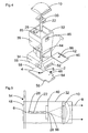
- FIG. 4 shows the tube 32 in an exploded view with the light emitter 2, the light guide 22, the aperture 40 and the transmitting optics 10, all in the tube to be ordered.
- the tube 32 consists of a light-absorbing plastic part and is preferably made of black plastic to avoid unnecessary light reflections.
- the tube 32 consists of a first chamber 34 for receiving the light emitter 2.
- a tubular connection 38 connects the first chamber 34 with a second chamber 36.
- the tube 32 has an insertion opening 44 for the panel 40, a slot 52 and a wedge snap 56 for the light emitter 2 on.
- the light transmitter 2 consists of a printed circuit board 48 and the transmission elements 4 applied to the printed circuit board 48.
- the transmitting elements 4 are preferably designed as light emitting diodes 6 for emitting the transmitted light 8 of several different wavelength ranges. In particular, these wavelengths correspond to the wavelengths of red, green and blue light.
- the light emitting diodes 6 are arranged in a row next to each other by means of solder mounting. In FIG. 8 the light transmitter 2 is shown separately. Other components for driving the light emitting diodes 6 may be provided on the circuit board 48. These are in FIG. 8 not shown.
- the printed circuit board 48 has two mounting sides for components and for the light emitting diodes 6. On the second component side light emitting diodes of a different design can be provided.
- the light emitting diodes 6 can be fitted from a second supply source on the back and the circuit board 48 are simply reversed, so that the light emitting diodes 6 can be mounted with the circuit board 48 to the light guide ,
- light emission diodes 6 can also be equipped with other optical properties on the second component side in order to produce a light contrast sensor with other optical properties of otherwise identical construction.
- the printed circuit board 48 has a nose 54 on one of its sides and a blunt tip 58 on the opposite side.
- the circuit board 48 is mounted in the tube 32 in the first chamber 34.
- the printed circuit board 48 is inserted obliquely with the nose 54 into the slot 52 of the tube 32 provided for the nose 54. The insertion is limited by paragraphs 55 of the circuit board 48.
- a small elevation 53 is arranged, with which the nose 54 of the circuit board 48 can be clamped in the slot 52 for play-free recording of the circuit board 48.
- the blunt tip 58 and the wedge-shaped receptacle 57 of the wedge snap closure 56 the circuit board 48 is held without play and stable in position by the wedge surfaces of the receptacle 57 and the sides of the blunt tip 58 against each other due to the clamping force in position slip.
- the position of the circuit board 48 is additionally determined by two boundary surfaces 60 and 61, which are arranged at a right angle to each other and formed by two walls of the first chamber 34. In this way, the light transmitter 2 consisting of printed circuit board 48 and transmitting elements 4 is precisely positioned and adjusted to the tube 32 mounted.
- the light guide 22 is inserted from the second chamber 36 in the direction of the first chamber 34 in the tubular connection 38.
- the lens 26 of the light guide 22 points in the direction of the first chamber 34.
- the lens 26 of the light guide is arranged in front of the light emission diodes 6.
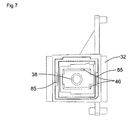
- the light guide 22 is replaced by a mounting plate receptacle 46 (FIG. Fig. 7 ) is positioned and locked between the second chamber 36 and tubular connection.
- FIG. 7 a view is shown frontally in the second chamber. In this case, the tubular connection 38 with the mounting plate receptacle 46 can be seen.
- the mounting plate 30 is aligned centered by a wedge-shaped expression of the mounting plate holder 46. In this position, the light guide 22 is held by the inserted into the insertion opening 44 aperture 40.
- the diaphragm 40 consists of a rectangular plate which has an aperture 86 ( Fig. 4 ).
- the aperture 40 is preferably made of metal. Metal has the advantage that the aperture 86 can be made very accurate in dimensions. By running in metal, the aperture 40 can be made very thin.
- the panel 40 additionally has a latching mechanism 42. After insertion of the diaphragm 40 in the tube 32 of the latching mechanism 42 engages in the provided in the tube 32 counterpart. A Insertion opening 44 for the panel 40 is located in the second chamber 36 of the tube 32. The panel 40 is latched by the latching mechanism 42 in the correct position and secured against displacement. As described above, the aperture 40 is inserted directly behind the mounting plate 30 of the light guide 22 and thereby has the additional function of holding the light guide 22 in its position.
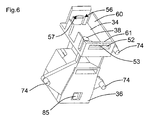
- the transmission optics 10 After attaching the aperture 40, the transmission optics 10 is mounted.
- the transmitting optics 10 is clipped at the opening of the second chamber 36 in the tube 32 by means of two locking devices 85.
- FIG. 5 shows a schematic representation of the optical components FIG. 4 with illustrated light path of the transmitted light 8 from the light emitter 2 via the light guide 22, the aperture 86 and the transmission optics 10.
- the tube 32 for receiving and fixing the individual components is shown for clarity as a simple box.
- the transmitted light 8 is emitted by the light emitting diodes 6, which are arranged directly in front of the lens 26 of the light guide 22 side by side. After the light beams have been coupled into the light guide 22, they are repeatedly totally reflected in the light guide 22 and thereby optimally mixed. After the light beams are mixed optimally they exit at the light exit side 28 from the light guide 22. After the stop 40, the rays hit the emitting optics 10, with which they are aligned in parallel.
- the small aperture 86 advantageously gives the smallest possible light source with the various well-mixed color components. As a result, a good image can be achieved on the receiver by means of the further optics.
- FIG. 6 is a view into the first chamber 34 shown, in which the tubular connection 38 for the light guide to the second chamber 36 can be seen.
- the tube 32 also has alignment pins 74. With the aid of this alignment pin 74, the tube 32 can be accurately positioned in the housing 3 and held in position.
- the housing has for this purpose pin openings, which can receive the alignment pin 74.
- FIG. 9 two openings 70 and 71 for a monitor receiving element 68 can be seen. Over these openings 70 and 71, the monitor receiving element 68 is arranged. Through the opening 70 in the tube 32, a scattered light component of the transmitted light 8 in the area of the transmitting elements 4 can be viewed by the monitor receiving element 68. On the other hand, a scattered light portion of the transmitted light in the region of the mounting plate 30 can be viewed through the opening 71.
- the monitor receiving element 68 is preferably formed as a monitor diode 72. With the help of the monitor diode 72, the scattered light and thus the transmitted light 8 can be monitored.
- the light emitting diodes 6 can be readjusted with the aid of the monitor diode 72 and the evaluation and control unit 16. With the help of the monitor diode 72, the brightness or the color composition of the transmitted light can also generally be monitored and adjusted and controlled with the aid of the evaluation and control unit 16.
Landscapes
- Physics & Mathematics (AREA)
- Spectroscopy & Molecular Physics (AREA)
- General Physics & Mathematics (AREA)
- Optical Couplings Of Light Guides (AREA)
- Eye Examination Apparatus (AREA)
- Push-Button Switches (AREA)
- Exposure Control For Cameras (AREA)
- Photo Coupler, Interrupter, Optical-To-Optical Conversion Devices (AREA)
- Non-Silver Salt Photosensitive Materials And Non-Silver Salt Photography (AREA)
- Investigating Or Analysing Biological Materials (AREA)
- Arrangement Of Elements, Cooling, Sealing, Or The Like Of Lighting Devices (AREA)
Applications Claiming Priority (1)
| Application Number | Priority Date | Filing Date | Title |
|---|---|---|---|
| DE102005017901A DE102005017901A1 (de) | 2005-04-18 | 2005-04-18 | Lichtkontrasttaster zur Erkennung von Marken |
Publications (2)
| Publication Number | Publication Date |
|---|---|
| EP1715313A1 EP1715313A1 (de) | 2006-10-25 |
| EP1715313B1 true EP1715313B1 (de) | 2008-05-21 |
Family
ID=36602700
Family Applications (1)
| Application Number | Title | Priority Date | Filing Date |
|---|---|---|---|
| EP06006461A Expired - Lifetime EP1715313B1 (de) | 2005-04-18 | 2006-03-29 | Lichtkontrasttaster zur Erkennung von Marken |
Country Status (5)
| Country | Link |
|---|---|
| EP (1) | EP1715313B1 (da) |
| AT (1) | ATE396386T1 (da) |
| DE (2) | DE102005017901A1 (da) |
| DK (1) | DK1715313T3 (da) |
| ES (1) | ES2306317T3 (da) |
Cited By (2)
| Publication number | Priority date | Publication date | Assignee | Title |
|---|---|---|---|---|
| DE102015115016A1 (de) | 2015-09-08 | 2017-03-09 | Leuze Electronic Gmbh + Co. Kg | Lichtkontrasttaster |
| DE102023119080A1 (de) | 2023-07-19 | 2025-01-23 | Wenglor sensoric elektronische Geräte GmbH | Sensor für marken |
Families Citing this family (5)
| Publication number | Priority date | Publication date | Assignee | Title |
|---|---|---|---|---|
| DE102014102420A1 (de) | 2014-02-25 | 2015-08-27 | Sick Ag | Optoelektronischer Sensor und Verfahren zur Objekterfassung in einem Überwachungsbereich |
| DE202014100836U1 (de) | 2014-02-25 | 2015-05-28 | Sick Ag | Optoelektronischer Sensor zur Objekterfassung in einem Überwachungsbereich |
| DE102015226431A1 (de) * | 2015-12-22 | 2017-06-22 | Robert Bosch Gmbh | Abdeckfoliensensoreinrichtung für Agraranwendungen, Verfahren zum Betreiben einer Abdeckfoliensensoreinrichtung |
| DE102019111927B4 (de) * | 2019-05-08 | 2024-07-18 | Sick Ag | Sendeeinheit und Empfangseinheit für einen optoelektronischen Sensor |
| EP3770567B1 (de) | 2019-07-23 | 2021-09-01 | Sick Ag | Optoelektronischer sensor |
Family Cites Families (9)
| Publication number | Priority date | Publication date | Assignee | Title |
|---|---|---|---|---|
| CH690471A5 (de) * | 1988-04-18 | 2000-09-15 | Mars Inc | Einrichtung zum Erkennen der Echtheit von Dokumenten. |
| EP0644504B1 (en) * | 1993-09-14 | 2000-08-16 | Symbol Technologies, Inc. | Scanner with multiple scan units |
| DE29505165U1 (de) * | 1995-03-27 | 1995-05-18 | Erwin Sick Gmbh Optik-Elektronik, 79183 Waldkirch | Farbsensoranordnung zum Lesen farbiger Markierungen |
| US5926262A (en) * | 1997-07-01 | 1999-07-20 | Lj Laboratories, L.L.C. | Apparatus and method for measuring optical characteristics of an object |
| DE19846002A1 (de) * | 1998-10-06 | 2000-04-13 | Sick Ag | Lichtkonstrasttaster |
| JP2000121440A (ja) * | 1998-10-15 | 2000-04-28 | Keyence Corp | 色識別装置 |
| US6924476B2 (en) * | 2002-11-25 | 2005-08-02 | Microvision, Inc. | Resonant beam scanner with raster pinch compensation |
| JP2002133932A (ja) * | 2000-10-20 | 2002-05-10 | Casio Comput Co Ltd | 光源素子 |
| US7232071B2 (en) * | 2003-11-14 | 2007-06-19 | Microvision, Inc. | Scanned beam imager |
-
2005
- 2005-04-18 DE DE102005017901A patent/DE102005017901A1/de not_active Withdrawn
-
2006
- 2006-03-29 ES ES06006461T patent/ES2306317T3/es not_active Expired - Lifetime
- 2006-03-29 EP EP06006461A patent/EP1715313B1/de not_active Expired - Lifetime
- 2006-03-29 DE DE502006000782T patent/DE502006000782D1/de not_active Expired - Lifetime
- 2006-03-29 DK DK06006461T patent/DK1715313T3/da active
- 2006-03-29 AT AT06006461T patent/ATE396386T1/de active
Cited By (3)
| Publication number | Priority date | Publication date | Assignee | Title |
|---|---|---|---|---|
| DE102015115016A1 (de) | 2015-09-08 | 2017-03-09 | Leuze Electronic Gmbh + Co. Kg | Lichtkontrasttaster |
| DE102015115016B4 (de) | 2015-09-08 | 2022-06-23 | Leuze Electronic Gmbh + Co. Kg | Lichtkontrasttaster |
| DE102023119080A1 (de) | 2023-07-19 | 2025-01-23 | Wenglor sensoric elektronische Geräte GmbH | Sensor für marken |
Also Published As
| Publication number | Publication date |
|---|---|
| DE502006000782D1 (de) | 2008-07-03 |
| ES2306317T3 (es) | 2008-11-01 |
| DK1715313T3 (da) | 2008-09-15 |
| DE102005017901A1 (de) | 2006-11-16 |
| ATE396386T1 (de) | 2008-06-15 |
| EP1715313A1 (de) | 2006-10-25 |
Similar Documents
| Publication | Publication Date | Title |
|---|---|---|
| DE102004046725B4 (de) | Gehäuse für ein Lichtgitter | |
| EP2011755B1 (de) | Vorrichtung zum strichförmigen Beleuchten einer laufenden Warenbahn | |
| EP1715313B1 (de) | Lichtkontrasttaster zur Erkennung von Marken | |
| EP4507923A1 (de) | Fahrzeugscheibe mit einer beleuchtungseinrichtung | |
| CH699818B1 (de) | Optoelektronischer Sensor mit einem Lichtsender. | |
| EP0735501B1 (de) | Farbsensoranordnung zum Lesen farbiger Markierungen | |
| DE102010043296B4 (de) | Lichtemittermodul mit Umlenkoptik | |
| DE102010043295B4 (de) | Lichtemittermodul | |
| DE112015005380T5 (de) | Flüssigkeitssensor | |
| DE102015115016B4 (de) | Lichtkontrasttaster | |
| EP1648809B1 (de) | Gehäuse für einen fadenspannungsaufnehmer | |
| DE10050817A1 (de) | Beleuchtungssystem für Kraftfahrzeugkomponenten | |
| EP0394909B1 (de) | Verfahren zur diffusen Beleuchtung einer Messfläche in einem Testträgeranalysegerät | |
| DE102007051681A1 (de) | Optoelektronischer Sensor | |
| DE102006016913A1 (de) | Optischer Sensor | |
| DE202020106752U1 (de) | Sensor | |
| EP1514750B1 (de) | Kombinierte Sensoranordnung zur Detektion von Umgebungslicht und Regen | |
| EP3324218B1 (de) | Mehrstrahllichtschranke | |
| EP2270435A2 (de) | Optischer Sensorfinger | |
| DE102005041998A1 (de) | Verfahren zur Justage eines abbildenden Elements sowie Messgerät justiert nach einem derartigen Verfahren | |
| EP3789659A2 (de) | Grundkörper für eine lichkonversions- oder beleuchtungseinrichtung | |
| EP3374775B1 (de) | Kontaktstift mit lichtquelle und kontaktstiftanordnung mit lichtquelle | |
| DE202016106394U1 (de) | Mehrstrahllichtschranke | |
| EP1686398B1 (de) | Optoelektronischer Sensor | |
| DE69727348T2 (de) | Photovervielfacher mit Seiteneintritt |
Legal Events
| Date | Code | Title | Description |
|---|---|---|---|
| PUAI | Public reference made under article 153(3) epc to a published international application that has entered the european phase |
Free format text: ORIGINAL CODE: 0009012 |
|
| AK | Designated contracting states |
Kind code of ref document: A1 Designated state(s): AT BE BG CH CY CZ DE DK EE ES FI FR GB GR HU IE IS IT LI LT LU LV MC NL PL PT RO SE SI SK TR |
|
| AX | Request for extension of the european patent |
Extension state: AL BA HR MK YU |
|
| 17P | Request for examination filed |
Effective date: 20061111 |
|
| RAP1 | Party data changed (applicant data changed or rights of an application transferred) |
Owner name: SICK AG |
|
| AKX | Designation fees paid |
Designated state(s): AT BE BG CH CY CZ DE DK EE ES FI FR GB GR HU IE IS IT LI LT LU LV MC NL PL PT RO SE SI SK TR |
|
| GRAP | Despatch of communication of intention to grant a patent |
Free format text: ORIGINAL CODE: EPIDOSNIGR1 |
|
| GRAS | Grant fee paid |
Free format text: ORIGINAL CODE: EPIDOSNIGR3 |
|
| GRAA | (expected) grant |
Free format text: ORIGINAL CODE: 0009210 |
|
| AK | Designated contracting states |
Kind code of ref document: B1 Designated state(s): AT BE BG CH CY CZ DE DK EE ES FI FR GB GR HU IE IS IT LI LT LU LV MC NL PL PT RO SE SI SK TR |
|
| REG | Reference to a national code |
Ref country code: GB Ref legal event code: FG4D Free format text: NOT ENGLISH |
|
| REG | Reference to a national code |
Ref country code: CH Ref legal event code: EP |
|
| REF | Corresponds to: |
Ref document number: 502006000782 Country of ref document: DE Date of ref document: 20080703 Kind code of ref document: P |
|
| REG | Reference to a national code |
Ref country code: IE Ref legal event code: FG4D Free format text: LANGUAGE OF EP DOCUMENT: GERMAN |
|
| REG | Reference to a national code |
Ref country code: SE Ref legal event code: TRGR |
|
| REG | Reference to a national code |
Ref country code: DK Ref legal event code: T3 |
|
| PG25 | Lapsed in a contracting state [announced via postgrant information from national office to epo] |
Ref country code: SI Free format text: LAPSE BECAUSE OF FAILURE TO SUBMIT A TRANSLATION OF THE DESCRIPTION OR TO PAY THE FEE WITHIN THE PRESCRIBED TIME-LIMIT Effective date: 20080521 |
|
| PG25 | Lapsed in a contracting state [announced via postgrant information from national office to epo] |
Ref country code: FI Free format text: LAPSE BECAUSE OF FAILURE TO SUBMIT A TRANSLATION OF THE DESCRIPTION OR TO PAY THE FEE WITHIN THE PRESCRIBED TIME-LIMIT Effective date: 20080521 |
|
| REG | Reference to a national code |
Ref country code: ES Ref legal event code: FG2A Ref document number: 2306317 Country of ref document: ES Kind code of ref document: T3 |
|
| NLV1 | Nl: lapsed or annulled due to failure to fulfill the requirements of art. 29p and 29m of the patents act | ||
| PG25 | Lapsed in a contracting state [announced via postgrant information from national office to epo] |
Ref country code: LV Free format text: LAPSE BECAUSE OF FAILURE TO SUBMIT A TRANSLATION OF THE DESCRIPTION OR TO PAY THE FEE WITHIN THE PRESCRIBED TIME-LIMIT Effective date: 20080521 Ref country code: NL Free format text: LAPSE BECAUSE OF FAILURE TO SUBMIT A TRANSLATION OF THE DESCRIPTION OR TO PAY THE FEE WITHIN THE PRESCRIBED TIME-LIMIT Effective date: 20080521 Ref country code: PL Free format text: LAPSE BECAUSE OF FAILURE TO SUBMIT A TRANSLATION OF THE DESCRIPTION OR TO PAY THE FEE WITHIN THE PRESCRIBED TIME-LIMIT Effective date: 20080521 |
|
| PG25 | Lapsed in a contracting state [announced via postgrant information from national office to epo] |
Ref country code: IS Free format text: LAPSE BECAUSE OF FAILURE TO SUBMIT A TRANSLATION OF THE DESCRIPTION OR TO PAY THE FEE WITHIN THE PRESCRIBED TIME-LIMIT Effective date: 20080921 |
|
| REG | Reference to a national code |
Ref country code: IE Ref legal event code: FD4D |
|
| PG25 | Lapsed in a contracting state [announced via postgrant information from national office to epo] |
Ref country code: CZ Free format text: LAPSE BECAUSE OF FAILURE TO SUBMIT A TRANSLATION OF THE DESCRIPTION OR TO PAY THE FEE WITHIN THE PRESCRIBED TIME-LIMIT Effective date: 20080521 Ref country code: IE Free format text: LAPSE BECAUSE OF FAILURE TO SUBMIT A TRANSLATION OF THE DESCRIPTION OR TO PAY THE FEE WITHIN THE PRESCRIBED TIME-LIMIT Effective date: 20080521 Ref country code: LT Free format text: LAPSE BECAUSE OF FAILURE TO SUBMIT A TRANSLATION OF THE DESCRIPTION OR TO PAY THE FEE WITHIN THE PRESCRIBED TIME-LIMIT Effective date: 20080521 |
|
| PG25 | Lapsed in a contracting state [announced via postgrant information from national office to epo] |
Ref country code: SK Free format text: LAPSE BECAUSE OF FAILURE TO SUBMIT A TRANSLATION OF THE DESCRIPTION OR TO PAY THE FEE WITHIN THE PRESCRIBED TIME-LIMIT Effective date: 20080521 Ref country code: PT Free format text: LAPSE BECAUSE OF FAILURE TO SUBMIT A TRANSLATION OF THE DESCRIPTION OR TO PAY THE FEE WITHIN THE PRESCRIBED TIME-LIMIT Effective date: 20081021 Ref country code: RO Free format text: LAPSE BECAUSE OF FAILURE TO SUBMIT A TRANSLATION OF THE DESCRIPTION OR TO PAY THE FEE WITHIN THE PRESCRIBED TIME-LIMIT Effective date: 20080521 |
|
| PLBE | No opposition filed within time limit |
Free format text: ORIGINAL CODE: 0009261 |
|
| STAA | Information on the status of an ep patent application or granted ep patent |
Free format text: STATUS: NO OPPOSITION FILED WITHIN TIME LIMIT |
|
| 26N | No opposition filed |
Effective date: 20090224 |
|
| PG25 | Lapsed in a contracting state [announced via postgrant information from national office to epo] |
Ref country code: EE Free format text: LAPSE BECAUSE OF FAILURE TO SUBMIT A TRANSLATION OF THE DESCRIPTION OR TO PAY THE FEE WITHIN THE PRESCRIBED TIME-LIMIT Effective date: 20080521 Ref country code: BG Free format text: LAPSE BECAUSE OF FAILURE TO SUBMIT A TRANSLATION OF THE DESCRIPTION OR TO PAY THE FEE WITHIN THE PRESCRIBED TIME-LIMIT Effective date: 20080821 |
|
| BERE | Be: lapsed |
Owner name: SICK A.G. Effective date: 20090331 |
|
| PG25 | Lapsed in a contracting state [announced via postgrant information from national office to epo] |
Ref country code: MC Free format text: LAPSE BECAUSE OF NON-PAYMENT OF DUE FEES Effective date: 20090331 |
|
| PG25 | Lapsed in a contracting state [announced via postgrant information from national office to epo] |
Ref country code: BE Free format text: LAPSE BECAUSE OF NON-PAYMENT OF DUE FEES Effective date: 20090331 |
|
| PG25 | Lapsed in a contracting state [announced via postgrant information from national office to epo] |
Ref country code: GR Free format text: LAPSE BECAUSE OF FAILURE TO SUBMIT A TRANSLATION OF THE DESCRIPTION OR TO PAY THE FEE WITHIN THE PRESCRIBED TIME-LIMIT Effective date: 20080822 |
|
| REG | Reference to a national code |
Ref country code: CH Ref legal event code: PL |
|
| PG25 | Lapsed in a contracting state [announced via postgrant information from national office to epo] |
Ref country code: CH Free format text: LAPSE BECAUSE OF NON-PAYMENT OF DUE FEES Effective date: 20100331 Ref country code: LI Free format text: LAPSE BECAUSE OF NON-PAYMENT OF DUE FEES Effective date: 20100331 |
|
| PG25 | Lapsed in a contracting state [announced via postgrant information from national office to epo] |
Ref country code: LU Free format text: LAPSE BECAUSE OF NON-PAYMENT OF DUE FEES Effective date: 20090329 |
|
| PG25 | Lapsed in a contracting state [announced via postgrant information from national office to epo] |
Ref country code: HU Free format text: LAPSE BECAUSE OF FAILURE TO SUBMIT A TRANSLATION OF THE DESCRIPTION OR TO PAY THE FEE WITHIN THE PRESCRIBED TIME-LIMIT Effective date: 20081122 |
|
| PG25 | Lapsed in a contracting state [announced via postgrant information from national office to epo] |
Ref country code: TR Free format text: LAPSE BECAUSE OF FAILURE TO SUBMIT A TRANSLATION OF THE DESCRIPTION OR TO PAY THE FEE WITHIN THE PRESCRIBED TIME-LIMIT Effective date: 20080521 |
|
| PG25 | Lapsed in a contracting state [announced via postgrant information from national office to epo] |
Ref country code: CY Free format text: LAPSE BECAUSE OF FAILURE TO SUBMIT A TRANSLATION OF THE DESCRIPTION OR TO PAY THE FEE WITHIN THE PRESCRIBED TIME-LIMIT Effective date: 20080521 |
|
| PGFP | Annual fee paid to national office [announced via postgrant information from national office to epo] |
Ref country code: AT Payment date: 20140320 Year of fee payment: 9 |
|
| REG | Reference to a national code |
Ref country code: AT Ref legal event code: MM01 Ref document number: 396386 Country of ref document: AT Kind code of ref document: T Effective date: 20150329 |
|
| PG25 | Lapsed in a contracting state [announced via postgrant information from national office to epo] |
Ref country code: AT Free format text: LAPSE BECAUSE OF NON-PAYMENT OF DUE FEES Effective date: 20150329 |
|
| REG | Reference to a national code |
Ref country code: FR Ref legal event code: PLFP Year of fee payment: 11 |
|
| PGFP | Annual fee paid to national office [announced via postgrant information from national office to epo] |
Ref country code: DK Payment date: 20160322 Year of fee payment: 11 |
|
| REG | Reference to a national code |
Ref country code: FR Ref legal event code: PLFP Year of fee payment: 12 |
|
| PGFP | Annual fee paid to national office [announced via postgrant information from national office to epo] |
Ref country code: GB Payment date: 20170327 Year of fee payment: 12 |
|
| REG | Reference to a national code |
Ref country code: DK Ref legal event code: EBP Effective date: 20170331 |
|
| REG | Reference to a national code |
Ref country code: FR Ref legal event code: PLFP Year of fee payment: 13 |
|
| PG25 | Lapsed in a contracting state [announced via postgrant information from national office to epo] |
Ref country code: DK Free format text: LAPSE BECAUSE OF NON-PAYMENT OF DUE FEES Effective date: 20170331 |
|
| PGFP | Annual fee paid to national office [announced via postgrant information from national office to epo] |
Ref country code: ES Payment date: 20180423 Year of fee payment: 13 |
|
| GBPC | Gb: european patent ceased through non-payment of renewal fee |
Effective date: 20180329 |
|
| PG25 | Lapsed in a contracting state [announced via postgrant information from national office to epo] |
Ref country code: GB Free format text: LAPSE BECAUSE OF NON-PAYMENT OF DUE FEES Effective date: 20180329 |
|
| PGFP | Annual fee paid to national office [announced via postgrant information from national office to epo] |
Ref country code: SE Payment date: 20190325 Year of fee payment: 14 |
|
| PGFP | Annual fee paid to national office [announced via postgrant information from national office to epo] |
Ref country code: DE Payment date: 20200324 Year of fee payment: 15 Ref country code: IT Payment date: 20200325 Year of fee payment: 15 |
|
| PGFP | Annual fee paid to national office [announced via postgrant information from national office to epo] |
Ref country code: FR Payment date: 20200325 Year of fee payment: 15 |
|
| REG | Reference to a national code |
Ref country code: ES Ref legal event code: FD2A Effective date: 20200728 |
|
| PG25 | Lapsed in a contracting state [announced via postgrant information from national office to epo] |
Ref country code: ES Free format text: LAPSE BECAUSE OF NON-PAYMENT OF DUE FEES Effective date: 20190330 |
|
| PG25 | Lapsed in a contracting state [announced via postgrant information from national office to epo] |
Ref country code: SE Free format text: LAPSE BECAUSE OF NON-PAYMENT OF DUE FEES Effective date: 20200330 |
|
| REG | Reference to a national code |
Ref country code: DE Ref legal event code: R119 Ref document number: 502006000782 Country of ref document: DE |
|
| PG25 | Lapsed in a contracting state [announced via postgrant information from national office to epo] |
Ref country code: FR Free format text: LAPSE BECAUSE OF NON-PAYMENT OF DUE FEES Effective date: 20210331 Ref country code: DE Free format text: LAPSE BECAUSE OF NON-PAYMENT OF DUE FEES Effective date: 20211001 |
|
| PG25 | Lapsed in a contracting state [announced via postgrant information from national office to epo] |
Ref country code: IT Free format text: LAPSE BECAUSE OF NON-PAYMENT OF DUE FEES Effective date: 20210329 |