EP1715313B1 - Light contrast scanner for identifying marks - Google Patents
Light contrast scanner for identifying marks Download PDFInfo
- Publication number
- EP1715313B1 EP1715313B1 EP06006461A EP06006461A EP1715313B1 EP 1715313 B1 EP1715313 B1 EP 1715313B1 EP 06006461 A EP06006461 A EP 06006461A EP 06006461 A EP06006461 A EP 06006461A EP 1715313 B1 EP1715313 B1 EP 1715313B1
- Authority
- EP
- European Patent Office
- Prior art keywords
- light
- light guide
- contrast scanner
- chamber
- scanner
- Prior art date
- Legal status (The legal status is an assumption and is not a legal conclusion. Google has not performed a legal analysis and makes no representation as to the accuracy of the status listed.)
- Expired - Lifetime
Links
Images


Classifications
-
- G—PHYSICS
- G01—MEASURING; TESTING
- G01J—MEASUREMENT OF INTENSITY, VELOCITY, SPECTRAL CONTENT, POLARISATION, PHASE OR PULSE CHARACTERISTICS OF INFRARED, VISIBLE OR ULTRAVIOLET LIGHT; COLORIMETRY; RADIATION PYROMETRY
- G01J3/00—Spectrometry; Spectrophotometry; Monochromators; Measuring colours
- G01J3/46—Measurement of colour; Colour measuring devices, e.g. colorimeters
Definitions
- the invention relates to a light contrast sensor for detecting marks and / or colors according to the preamble of claim 1.
- the light contrast sensor includes a light transmitter for emitting transmitted light through a transmitting optics, a light receiver for receiving reflected or remitted transmitted light and a control and evaluation circuit.
- the light transmitter is designed to emit transmitted light of several different test wavelength ranges. The different colors are combined or mixed to form a common transmission beam by means of a cylindrical lens.
- the light contrast sensor requires a multi-part and complex transmission optics for spatially overlapping imaging of the transmitted light for several test wavelength ranges, so that the overlapping area forms a common monitoring area of the light contrast sensor.
- the cylindrical lens is a part of the transmission optics, by which the transmitted light of a transmitting element can be ultimately imaged on the surveillance area as a cross-section of longitudinally oval-shaped transmission beams. Through the cylindrical lens colors are mixed only insufficient. Elaborate is the assembly, the production and alignment of the individual parts of the transmission optics to each other. As a result, the production of such a light contrast sensor is costly.
- the multi-part transmission optics and in particular the cylindrical lens require by their size and the necessary distances a lot of space. Especially with this type of sensors, it is desirable to realize particularly small designs.
- Another light contrast button for detecting colors is from the EP 0 994 334 A2 known.
- the object of the invention is to provide an improved light contrast sensor for detecting marks and / or colors.
- the object is achieved according to the invention according to claim 1, characterized in that the light contrast sensor for detecting marks and / or colors with a light transmitter with spatially adjacent transmitting elements, in particular light emitting diodes for emitting transmitted light of several different wavelength ranges, in particular in the red, green and blue wavelength range of light, is trained.
- the light contrast button includes a transmission optics.
- a light receiver for receiving reflected or remitted transmitted light is provided in the light contrast button a control and evaluation circuit is mounted. At least one means for mixing different color components of the transmitted light is present, wherein the means is formed by a light guide and the light emitter and the light guide are arranged in a common tube.
- the advantage of this inventive design of the light contrast sensor is that the mixing of the different color components is accomplished with the very inexpensive and optimal for this task optical fiber.
- the light guide is characterized by the property of passing light through total reflection, ideal for the solution to mix different color components in a small space.
- Especially the small design is a great advantage for this type of sensors.
- the light emitter and the light guide are arranged in a common tube, this provides a common basis for the mounting of the Lichtsen-ders and the light guide.
- the reference dimensions of the arrangement are determined via mounting surfaces of the components and corresponding stop surfaces on the tube. In this way, the components light emitter and light guide need not be aligned separately.
- the length of the light guide is advantageously at least 3.5 times a transverse dimension of the light guide.
- the light guide is advantageously formed on the light emitter facing coupling surface as a lens.
- the lens is formed integrally with the light guide.
- the light guide advantageously has a rectangular cross-section.
- the rectangular cross section is particularly adapted to the arrangement of the transmitting elements.
- the rectangular shape also offers the advantage of a very compact design of the light guide.
- the length of the light guide is at least 7 times the shorter side of the rectangular cross section.
- the light guide consists of plastic transparent to the transmitted light. Through the use of plastic, the light guide is particularly inexpensive to produce. In particular, suitable manufacturing methods such as the injection molding process allow the production of the light guide at low cost.
- the light guide off Plastic is easy to work with and assemble. Risk of breakage, eg with glass, does not exist. Due to the low weight of the light guide, this is particularly suitable for high vibration and shock requirements of the light contrast sensor.
- the light guide has on its light exit side on a mounting plate, which is advantageously integrally connected to the light guide.
- the mounting plate of the light guide can be produced together with the light guide in one step.
- the mounting plate of the light guide is thus accurately aligned with the light guide. This allows a particularly simple installation of the light guide.
- the mounting plate is advantageously connected only at the corners of the rectangular cross-section with the light guide and arranged perpendicular to the light guide. Due to the exclusive connection of the mounting plate at the corners of the light guide the property of the total reflection of the light guide is minimally affected.
- the vertical arrangement of the mounting plate to the light guide allows a particularly simple installation of the light guide, if, for. the mounting plate is mounted against a stop.
- the tube advantageously has a first chamber, a second chamber and a tubular connection of the two chambers.
- the tubular connection of the light guide is arranged and the coupling surface of the light guide is arranged in the direction of the first chamber in which the light emitter is arranged.
- the arrangement of the chambers and the tubular connection allows a protected modular construction of the components on and in the tube.
- a diaphragm In the second chamber and on the light exit side of the light guide, a diaphragm is arranged.
- the diaphragm is advantageously also mounted in the tube and is thereby aligned with the other components in particular to the light exit side of the light guide.
- the aperture advantageously has a latching mechanism for mounting in the second chamber of the tube.
- the latching mechanism is integrally integrated in the panel.
- the aperture can thus be produced very inexpensively and be mounted.
- the second chamber has an insertion opening for mounting the panel in order to insert the panel into the tube. Through the insertion in the tube, the aperture is positioned exactly and is aligned without further assembly steps.
- the latch mechanism holds the bezel in the correct position. When exposed to shock or vibration, the bezel can not move from its intended position.
- the aperture is preferably formed of metal.
- the aperture can be formed very precisely.
- the aperture can also be made very thin and thus save space.
- the mounting plate of the light guide is kept positioned in the tube by means of the inserted aperture.
- a Montagenplatten technique is provided with wedge-shaped sides for adjusting the mounting plate.
- the light transmitter is arranged on a printed circuit board, and the first chamber of the tube has a printed circuit board receptacle.
- the tube has a slot for receiving a nose of the circuit board and a wedge snap closure for receiving a side facing away from the nose of the circuit board, which is formed as a blunt tip.
- the transmission elements applied to the printed circuit board are aligned and mounted exactly to the lens of the optical waveguide which projects through the tubular connection into the first chamber.
- the circuit board receptacle in addition to two adjacent stop sides, against which the circuit board is held by the wedge snap in tension in position.
- the abutment sides are formed by chamber walls of the first chamber.
- the circuit board is advantageously equipped on both sides with transmitting elements. As a result, different mounting variants of the circuit board can be realized with only one circuit board.
- the second component side can be equipped with alternative light emitting diodes with other ratios. This not only increases the variety of variants in the simplest way, but it can also be resorted to without design changes to other diodes in delivery bottlenecks of the light emitting diodes.
- the tube has an opening for a monitor receiving element, in particular a monitor diode.
- a monitor diode By means of this monitor diode, the wavelength and the intensity as well as the switching behavior of the light emitting diodes can be monitored or checked, for example by observing stray light of the actual transmitted light.
- the intensity of the transmitting elements can be readjusted via the control circuit.
- scattered light can be viewed directly from the transmitting elements or scattered light on the mounting plate of the light guide.
- the tube has alignment pins for aligned recording in a housing of the light contrast button.
- the tube with the optical components is advantageously aligned directly on the housing of the light contrast scanner.
- the alignment pins of the tube and pin holes of the housing are accurate manufactured, which requires the optical system and guarantees proper operation.
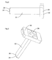
- FIG. 1 shows a schematic representation of a light contrast button 1.
- the light contrast button is housed in a housing 3.
- a light emitter 2 and a light receiver 12 is arranged in the housing 3.
- the light transmitter 2 and a light receiver 12 are connected to a control and evaluation circuit 16.
- the light transmitter 2 is arranged in a tube 32.
- a light guide 22, a diaphragm 40 and a transmission optical system 10 is further arranged.
- the transmitted from the light emitter 2 transmitted light strikes the light guide and passes to the aperture 40 and the transmitting optics 10 on a beam splitter 82.
- the beam splitter 82 divides the transmitted light in a proportion in the direction of a first objective lens 80 and in a proportion in the direction of a second objective lens 80 'up.
- the light contrast sensor 1 can selectively emit or receive the transmitted light or also the received light in two different directions.
- One of the two openings is closed during operation of the light contrast pushbutton 1 by a closure cap.
- the user is thus able to flexibly use one of the two light exit sides for his application.
- the light transmitter 2 is designed in such a way that sufficient light is emitted for color recognition via each of the objective optics 80 and 80 '.
- the transmitted light 8 reaches a contrast mark or a color mark.
- the light is reflected by this mark and hits the objective optics 80 or 80 'again.
- Reflected light 14 impinges on the beam splitter 82 and then on a receiving optical system 84.
- the receiving optical system 84 focuses the received light 14 onto the light receiver 12.
- the signal of the light receiver 12 is evaluated and, for example, generates a switching signal depending on the detected color.
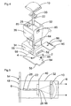
- the light guide 22 is shown in a side view.
- the light guide 22 has a coupling-in surface 24.
- the coupling surface 24 is formed as a lens 26.
- the lens 26 is integrally connected to the light guide 22. This results in no additional optical interface between lens 26 and light guide 22.
- the light guide 22 is elongated with a Length to cross-sectional dimension ratio of at least 3.5.
- the light guide 22 has on the opposite side of the coupling surface 24, on a light exit side 28 a mounting plate 30.
- the mounting plate 30 is arranged at right angles to the light guide 22.
- the light guide 22 is shown in a perspective view to illustrate the constructive expression of the light guide 22.
- the elongated light guide 22 is formed with a rectangular cross-section. As a result of this rectangular shape, the light of transmitting elements arranged side by side in a row can reach the light guide 22 particularly well via the correspondingly pronounced lens 26.
- the various color components of the transmitted light are mixed by multiple total reflection of the light along the length of the light guide 22.
- the light guide 22 is connected to maintain the total reflection properties of the light guide 22 only at the corners of the light guide 22 to the mounting plate 30. After the light has passed through the light guide 22, it exits at the light exit side 28 of the light guide 22.
- the mounting plate 30 is arranged perpendicular to the light guide 22.
- the mounting plate 30 is integrally connected to the optical fiber 22 with a fixed reference dimension. In this way, the light guide 22 can be aligned over the mounting plate 30 and mounted in the tube 32.
- the light guide 22 is advantageously made of a transparent plastic.
- the plastic is particularly well suited for cost-effective production by injection molding. Both the material and the manufacturing process is particularly cost-effective.
- the plastic is particularly stable and lightweight compared to other materials such. Glass.
- the plastic is also particularly well suited for high demands on vibration and shock loads of the light contrast push button 1. Due to the high stability and low weight of the light guide 22, there is minimal mechanical stress on the light guide 22 and connected to the light guide 22 components.
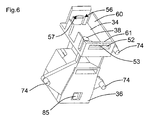
- FIG. 4 shows the tube 32 in an exploded view with the light emitter 2, the light guide 22, the aperture 40 and the transmitting optics 10, all in the tube to be ordered.
- the tube 32 consists of a light-absorbing plastic part and is preferably made of black plastic to avoid unnecessary light reflections.
- the tube 32 consists of a first chamber 34 for receiving the light emitter 2.
- a tubular connection 38 connects the first chamber 34 with a second chamber 36.
- the tube 32 has an insertion opening 44 for the panel 40, a slot 52 and a wedge snap 56 for the light emitter 2 on.
- the light transmitter 2 consists of a printed circuit board 48 and the transmission elements 4 applied to the printed circuit board 48.
- the transmitting elements 4 are preferably designed as light emitting diodes 6 for emitting the transmitted light 8 of several different wavelength ranges. In particular, these wavelengths correspond to the wavelengths of red, green and blue light.
- the light emitting diodes 6 are arranged in a row next to each other by means of solder mounting. In FIG. 8 the light transmitter 2 is shown separately. Other components for driving the light emitting diodes 6 may be provided on the circuit board 48. These are in FIG. 8 not shown.
- the printed circuit board 48 has two mounting sides for components and for the light emitting diodes 6. On the second component side light emitting diodes of a different design can be provided.
- the light emitting diodes 6 can be fitted from a second supply source on the back and the circuit board 48 are simply reversed, so that the light emitting diodes 6 can be mounted with the circuit board 48 to the light guide ,
- light emission diodes 6 can also be equipped with other optical properties on the second component side in order to produce a light contrast sensor with other optical properties of otherwise identical construction.
- the printed circuit board 48 has a nose 54 on one of its sides and a blunt tip 58 on the opposite side.
- the circuit board 48 is mounted in the tube 32 in the first chamber 34.
- the printed circuit board 48 is inserted obliquely with the nose 54 into the slot 52 of the tube 32 provided for the nose 54. The insertion is limited by paragraphs 55 of the circuit board 48.
- a small elevation 53 is arranged, with which the nose 54 of the circuit board 48 can be clamped in the slot 52 for play-free recording of the circuit board 48.
- the blunt tip 58 and the wedge-shaped receptacle 57 of the wedge snap closure 56 the circuit board 48 is held without play and stable in position by the wedge surfaces of the receptacle 57 and the sides of the blunt tip 58 against each other due to the clamping force in position slip.
- the position of the circuit board 48 is additionally determined by two boundary surfaces 60 and 61, which are arranged at a right angle to each other and formed by two walls of the first chamber 34. In this way, the light transmitter 2 consisting of printed circuit board 48 and transmitting elements 4 is precisely positioned and adjusted to the tube 32 mounted.
- the light guide 22 is inserted from the second chamber 36 in the direction of the first chamber 34 in the tubular connection 38.
- the lens 26 of the light guide 22 points in the direction of the first chamber 34.
- the lens 26 of the light guide is arranged in front of the light emission diodes 6.
- the light guide 22 is replaced by a mounting plate receptacle 46 (FIG. Fig. 7 ) is positioned and locked between the second chamber 36 and tubular connection.
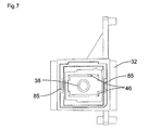
- FIG. 7 a view is shown frontally in the second chamber. In this case, the tubular connection 38 with the mounting plate receptacle 46 can be seen.
- the mounting plate 30 is aligned centered by a wedge-shaped expression of the mounting plate holder 46. In this position, the light guide 22 is held by the inserted into the insertion opening 44 aperture 40.
- the diaphragm 40 consists of a rectangular plate which has an aperture 86 ( Fig. 4 ).
- the aperture 40 is preferably made of metal. Metal has the advantage that the aperture 86 can be made very accurate in dimensions. By running in metal, the aperture 40 can be made very thin.
- the panel 40 additionally has a latching mechanism 42. After insertion of the diaphragm 40 in the tube 32 of the latching mechanism 42 engages in the provided in the tube 32 counterpart. A Insertion opening 44 for the panel 40 is located in the second chamber 36 of the tube 32. The panel 40 is latched by the latching mechanism 42 in the correct position and secured against displacement. As described above, the aperture 40 is inserted directly behind the mounting plate 30 of the light guide 22 and thereby has the additional function of holding the light guide 22 in its position.
- the transmission optics 10 After attaching the aperture 40, the transmission optics 10 is mounted.
- the transmitting optics 10 is clipped at the opening of the second chamber 36 in the tube 32 by means of two locking devices 85.
- FIG. 5 shows a schematic representation of the optical components FIG. 4 with illustrated light path of the transmitted light 8 from the light emitter 2 via the light guide 22, the aperture 86 and the transmission optics 10.
- the tube 32 for receiving and fixing the individual components is shown for clarity as a simple box.
- the transmitted light 8 is emitted by the light emitting diodes 6, which are arranged directly in front of the lens 26 of the light guide 22 side by side. After the light beams have been coupled into the light guide 22, they are repeatedly totally reflected in the light guide 22 and thereby optimally mixed. After the light beams are mixed optimally they exit at the light exit side 28 from the light guide 22. After the stop 40, the rays hit the emitting optics 10, with which they are aligned in parallel.
- the small aperture 86 advantageously gives the smallest possible light source with the various well-mixed color components. As a result, a good image can be achieved on the receiver by means of the further optics.
- FIG. 6 is a view into the first chamber 34 shown, in which the tubular connection 38 for the light guide to the second chamber 36 can be seen.
- the tube 32 also has alignment pins 74. With the aid of this alignment pin 74, the tube 32 can be accurately positioned in the housing 3 and held in position.
- the housing has for this purpose pin openings, which can receive the alignment pin 74.
- FIG. 9 two openings 70 and 71 for a monitor receiving element 68 can be seen. Over these openings 70 and 71, the monitor receiving element 68 is arranged. Through the opening 70 in the tube 32, a scattered light component of the transmitted light 8 in the area of the transmitting elements 4 can be viewed by the monitor receiving element 68. On the other hand, a scattered light portion of the transmitted light in the region of the mounting plate 30 can be viewed through the opening 71.
- the monitor receiving element 68 is preferably formed as a monitor diode 72. With the help of the monitor diode 72, the scattered light and thus the transmitted light 8 can be monitored.
- the light emitting diodes 6 can be readjusted with the aid of the monitor diode 72 and the evaluation and control unit 16. With the help of the monitor diode 72, the brightness or the color composition of the transmitted light can also generally be monitored and adjusted and controlled with the aid of the evaluation and control unit 16.
Landscapes
- Physics & Mathematics (AREA)
- Spectroscopy & Molecular Physics (AREA)
- General Physics & Mathematics (AREA)
- Optical Couplings Of Light Guides (AREA)
- Eye Examination Apparatus (AREA)
- Push-Button Switches (AREA)
- Exposure Control For Cameras (AREA)
- Photo Coupler, Interrupter, Optical-To-Optical Conversion Devices (AREA)
- Non-Silver Salt Photosensitive Materials And Non-Silver Salt Photography (AREA)
- Investigating Or Analysing Biological Materials (AREA)
- Arrangement Of Elements, Cooling, Sealing, Or The Like Of Lighting Devices (AREA)
Abstract
Description
Die Erfindung betrifft einen Lichtkontrasttaster zur Erkennung von Marken und/oder Farben nach dem Oberbegriff des Anspruchs 1.The invention relates to a light contrast sensor for detecting marks and / or colors according to the preamble of
Aus der
Dieser Lichtkontrasttaster weist jedoch wesentliche Nachteile auf. So benötigt der Lichtkontrasttaster eine mehrteilige und aufwändige Sendeoptik zur räumlich überlappenden Abbildung des Sendelichts für mehrere Testwellenlängenbereiche, so dass der überlappende Bereich einen gemeinsamen Überwachungsbereich des Lichtkontrasttasters bildet. Die Zylinderlinse ist ein Teil der Sendeoptik, durch die das Sendelicht eines Sendeelements letztlich jeweils als ein Querschnitt längsovalförmiger Sendestrahlen auf den Überwachungsbereich abbildbar ist. Durch die Zylinderlinse werden Farben nur unzureichend gemischt. Aufwändig ist die Montage, die Herstellung und die Ausrichtung der einzelnen Teile der Sendeoptik zueinander. Dadurch ist die Herstellung eines solchen Lichtkontrasttasters kostenintensiv. Die mehrteilige Sendeoptik und insbesondere die Zylinderlinse benötigen durch ihre Größe und die notwendigen Abstände sehr viel Platz. Gerade bei dieser Art von Sensoren ist es aber wünschenswert besonders kleine Bauformen zu realisieren.However, this light contrast button has significant disadvantages. Thus, the light contrast sensor requires a multi-part and complex transmission optics for spatially overlapping imaging of the transmitted light for several test wavelength ranges, so that the overlapping area forms a common monitoring area of the light contrast sensor. The cylindrical lens is a part of the transmission optics, by which the transmitted light of a transmitting element can be ultimately imaged on the surveillance area as a cross-section of longitudinally oval-shaped transmission beams. Through the cylindrical lens colors are mixed only insufficient. Elaborate is the assembly, the production and alignment of the individual parts of the transmission optics to each other. As a result, the production of such a light contrast sensor is costly. The multi-part transmission optics and in particular the cylindrical lens require by their size and the necessary distances a lot of space. Especially with this type of sensors, it is desirable to realize particularly small designs.
Einen anderen Lichtkontrasttaster zur Erkennung von Farben ist aus der
Der Erfindung liegt die Aufgabe zugrunde, einen verbesserten Lichtkontrasttaster zur Erkennung von Marken und/oder Farben bereitzustellen.The object of the invention is to provide an improved light contrast sensor for detecting marks and / or colors.
Die Aufgabe wird erfindungsgemäß nach Anspruch 1 dadurch gelöst, dass der Lichtkontrasttaster zur Erkennung von Marken und/oder Farben mit einem Lichtsender mit räumlich benachbarten Sendeelementen, insbesondere Lichtemissionsdioden zum Aussenden von Sendelicht mehrerer verschiedener Wellenlängenbereiche, insbesondere im roten, grünen und blauen Wellenlängenbereich des Lichtes, ausgebildet ist. Weiterhin beinhaltet der Lichtkontrasttaster eine Sendeoptik. Darüber hinaus ist ein Lichtempfänger zum Empfang von reflektiertem oder remittiertem Sendelicht vorgesehen. In dem Lichtkontrasttaster ist eine Steuer- und Auswerteschaltung angebracht. Wenigstens ein Mittel zum Durchmischen verschiedener Farbanteile des Sendelichts ist vorhanden, wobei das Mittel durch einen Lichtleiter gebildet ist und der Lichtsender und der Lichtleiter in einem gemeinsamen Tubus angeordnet sind.The object is achieved according to the invention according to
Der Vorteil dieser erfindungsgemäßen Ausbildung des Lichtkontrasttasters liegt darin, dass die Durchmischung der verschiedenen Farbanteile mit dem sehr preiswerten und für diese Aufgabe optimal ausgebildeten Lichtleiter bewerkstelligt wird. Der Lichtleiter eignet sich durch die Eigenschaft, Licht über Totalreflexion weiterzuleiten, ideal für die Lösung, verschiedene Farbanteile auf kleinstem Raum zu durchmischen. Gerade die kleine Bauform stellt einen großen Vorteil für diese Art von Sensoren dar. So können mit Hilfe des verwendeten Lichtleiters die Kosten für einen solchen Sensor enorm reduziert und gleichzeitig kann die Baugröße des Sensors verringert werden.The advantage of this inventive design of the light contrast sensor is that the mixing of the different color components is accomplished with the very inexpensive and optimal for this task optical fiber. The light guide is characterized by the property of passing light through total reflection, ideal for the solution to mix different color components in a small space. Especially the small design is a great advantage for this type of sensors. Thus, with the help of the optical fiber used, the cost of such a sensor can be reduced enormously and at the same time the size of the sensor can be reduced.
Dadurch dass der Lichtsender und der Lichtleiter in einem gemeinsamen Tubus angeordnet sind stellt dieser eine gemeinsame Basis für die Montage des Lichtsen-ders und des Lichtleiters dar. Die Referenzmaße der Anordnung werden dabei über Montageflächen der Komponenten und entsprechende Anschlagflächen an dem Tubus bestimmt. Auf diese Weise brauchen die Komponenten Lichtsender und Lichtleiter nicht gesondert zueinander ausgerichtet werden.The fact that the light emitter and the light guide are arranged in a common tube, this provides a common basis for the mounting of the Lichtsen-ders and the light guide. The reference dimensions of the arrangement are determined via mounting surfaces of the components and corresponding stop surfaces on the tube. In this way, the components light emitter and light guide need not be aligned separately.
Die Länge des Lichtleiters beträgt vorteilhaft wenigstens das 3,5-fache einer Querabmessung des Lichtleiters. Durch dieses Verhältnis der Länge des Lichtleiters zum Durchmesser wird eine ausreichend gute Durchmischung durch häufige Reflexionen bei gleichzeitig geringsten baulichen Abmessungen erreicht. Bei einem Durchmesser von ca. 2 mm beträgt die Länge des Lichtleiters nur ca. 7 mm.The length of the light guide is advantageously at least 3.5 times a transverse dimension of the light guide. By this ratio of the length of the light guide to the diameter of a sufficiently good mixing is achieved by frequent reflections at the same time minimal structural dimensions. With a diameter of about 2 mm, the length of the light guide is only about 7 mm.
Zusätzlich ist der Lichtleiter an der dem Lichtsender zugewandten Einkoppelfläche vorteilhaft als Linse ausgebildet ist. Durch diese Linse wird das Licht des Lichtsenders mit räumlich nebeneinander benachbarten Sendeelementen, die in einer Reihe nebeneinander angeordnet sind, insbesondere Lichtemissionsdioden zum Aussenden von Sendelicht mehrerer verschiedener Wellenlängenbereiche, insbesondere im roten, grünen und blauen Wellenlängenbereich des Lichtes besonders optimal in den Lichtleiter eingekoppelt. Die Linse ist dabei einstückig mit dem Lichtleiter ausgebildet. Vorteilhaft kann bei Einkopplung mit einer Linse ein im Querschnitt kleiner und damit auch in seiner Länge kurzer, entsprechend preisgünstiger und eine kleine Bauform erlaubender Lichtleiter eingesetzt werden.In addition, the light guide is advantageously formed on the light emitter facing coupling surface as a lens. Through this lens, the light of the light emitter with spatially adjacent adjacent transmitting elements, which are arranged in a row next to each other, in particular light emitting diodes for emitting transmitted light of several different wavelength ranges, especially in the red, green and blue wavelength range of light particularly optimally coupled into the light guide. The lens is formed integrally with the light guide. When coupled with a lens, it is advantageously possible to use a light guide which is smaller in cross-section and thus also shorter in length, correspondingly less expensive and has a smaller design.
Der Lichtleiter weist vorteilhaft einen rechteckigen Querschnitt auf. Dadurch kann das Licht von räumlich in einer Reihe benachbarten Sendeelemente besonders gut in den Lichtleiter gelangen. Der rechteckige Querschnitt ist dabei besonders auf die Anordnung der Sendelemente angepasst. Die Rechteckform bietet auch den Vorteil einer sehr kompakten Ausführung des Lichtleiters. Die Länge des Lichtleiters beträgt dazu wenigstens das 7-fache der kürzeren Seite des rechteckigen Querschnitts.The light guide advantageously has a rectangular cross-section. As a result, the light from spatially in a row adjacent transmitting elements can get into the light guide particularly well. The rectangular cross section is particularly adapted to the arrangement of the transmitting elements. The rectangular shape also offers the advantage of a very compact design of the light guide. The length of the light guide is at least 7 times the shorter side of the rectangular cross section.
Der Lichtleiter besteht aus für das Sendelicht transparentem Kunststoff. Durch die Verwendung von Kunststoff ist der Lichtleiter besonders preisgünstig herstellbar. Insbesondere geeignete Herstellungsverfahren wie das Spritzgussverfahren ermöglichen die Herstellung des Lichtleiters mit geringen Kosten. Der Lichtleiter aus Kunststoff ist leicht zu verarbeiten und zu montieren. Bruchgefahr wie z.B. bei Glas besteht nicht. Durch das geringe Gewicht des Lichtleiters eignet sich dieser besonders bei hohen Schwing- und Schockanforderungen an den Lichtkontrasttaster.The light guide consists of plastic transparent to the transmitted light. Through the use of plastic, the light guide is particularly inexpensive to produce. In particular, suitable manufacturing methods such as the injection molding process allow the production of the light guide at low cost. The light guide off Plastic is easy to work with and assemble. Risk of breakage, eg with glass, does not exist. Due to the low weight of the light guide, this is particularly suitable for high vibration and shock requirements of the light contrast sensor.
Der Lichtleiter weist an seiner Lichtaustrittsseite eine Montageplatte auf, die mit dem Lichtleiter vorteilhaft einstückig verbunden ist. Auf diese Weise kann die Montageplatte des Lichtleiters zusammen mit dem Lichtleiter in einem Verfahrensschritt hergestellt werden. Die Montageplatte des Lichtleiters ist somit auf den Lichtleiter genau ausgerichtet. Dies ermöglicht eine besonders einfache Montage des Lichtleiters.The light guide has on its light exit side on a mounting plate, which is advantageously integrally connected to the light guide. In this way, the mounting plate of the light guide can be produced together with the light guide in one step. The mounting plate of the light guide is thus accurately aligned with the light guide. This allows a particularly simple installation of the light guide.
Die Montageplatte ist vorteilhaft nur an den Ecken des rechteckigen Querschnitts mit dem Lichtleiter verbunden und senkrecht zu dem Lichtleiter angeordnet. Durch die ausschließliche Verbindung der Montageplatte an den Ecken des Lichtleiters wird die Eigenschaft der Totalreflexion des Lichtleiters geringst möglich beeinträchtigt. Die senkrechte Anordnung der Montageplatte zum Lichtleiter ermöglicht eine besonders einfache Montage des Lichtleiters, wenn z.B. die Montageplatte gegen einen Anschlag montiert wird.The mounting plate is advantageously connected only at the corners of the rectangular cross-section with the light guide and arranged perpendicular to the light guide. Due to the exclusive connection of the mounting plate at the corners of the light guide the property of the total reflection of the light guide is minimally affected. The vertical arrangement of the mounting plate to the light guide allows a particularly simple installation of the light guide, if, for. the mounting plate is mounted against a stop.
Der Tubus weist vorteilhaft eine erste Kammer, eine zweite Kammer und eine schlauchförmige Verbindung der beiden Kammern auf. In der schlauchförmigen Verbindung ist der Lichtleiter angeordnet und die Einkoppelfläche des Lichtleiters ist in Richtung der ersten Kammer angeordnet, in der der Lichtsender angeordnet wird. Die Anordnung der Kammern und der schlauchförmigen Verbindung erlaubt einen geschützten modularen Aufbau der Komponenten an und in dem Tubus.The tube advantageously has a first chamber, a second chamber and a tubular connection of the two chambers. In the tubular connection of the light guide is arranged and the coupling surface of the light guide is arranged in the direction of the first chamber in which the light emitter is arranged. The arrangement of the chambers and the tubular connection allows a protected modular construction of the components on and in the tube.
In der zweiten Kammer und an der Lichtaustrittsseite des Lichtleiters ist eine Blende angeordnet. Die Blende wird vorteilhaft ebenfalls in dem Tubus montiert und ist dadurch zu den anderen Komponenten insbesondere zu der Lichtaustrittseite des Lichtleiters ausgerichtet. Die Blende weist vorteilhaft einen Einrastmechanismus auf zur Montage in der zweiten Kammer des Tubus. Der Einrastmechanismus ist dabei einstückig in die Blende integriert. Die Blende kann somit sehr preisgünstig hergestellt und montiert werden. Die zweite Kammer weist zur Montage der Blende eine Einschuböffnung auf zum Einschieben der Blende in den Tubus. Durch den Einschub im Tubus wird die Blende exakt positioniert und ist ohne weitere Montageschritte richtig ausgerichtet. Der Einrastmechanismus hält die Blende in der richtigen Position. Bei Beanspruchungen wie Schock oder Vibration kann die Blende sich nicht aus der vorgesehenen Position bewegen.In the second chamber and on the light exit side of the light guide, a diaphragm is arranged. The diaphragm is advantageously also mounted in the tube and is thereby aligned with the other components in particular to the light exit side of the light guide. The aperture advantageously has a latching mechanism for mounting in the second chamber of the tube. The latching mechanism is integrally integrated in the panel. The aperture can thus be produced very inexpensively and be mounted. The second chamber has an insertion opening for mounting the panel in order to insert the panel into the tube. Through the insertion in the tube, the aperture is positioned exactly and is aligned without further assembly steps. The latch mechanism holds the bezel in the correct position. When exposed to shock or vibration, the bezel can not move from its intended position.
Um die Genauigkeit der Blendenöffnung zu erhöhen ist die Blende vorzugsweise aus Metall gebildet. Dadurch kann die Blende sehr präzise ausgebildet werden. Durch die Verwendung von Metall kann die Blende auch sehr dünn und damit platzsparend ausgebildet werden.In order to increase the accuracy of the aperture, the aperture is preferably formed of metal. As a result, the aperture can be formed very precisely. Through the use of metal, the aperture can also be made very thin and thus save space.
In Weiterbildung der Erfindung wird die Montageplatte des Lichtleiters in dem Tubus mittels der eingeschobenen Blende positioniert gehalten. Vor dem Einschieben der Blende wird der Lichtleiter aus Richtung der zweiten Kammer in die schlauchförmige Verbindung eingeschoben. In der zweiten Kammer ist eine Montagenplattenaufnahme vorgesehen mit keilförmig angeordneten Seiten zur justierten Aufnahme der Montageplatte. Durch das Einschieben der Blende wird der Lichtleiter mit der Montageplatte in der Montagenplattenaufnahme gehalten und positioniert. Der Lichtleiter und die Blende sind somit in dem Tubus einfach und ohne zusätzliche Montagekomponenten wie Kleber oder Schrauben angeordnet.In a further development of the invention, the mounting plate of the light guide is kept positioned in the tube by means of the inserted aperture. Before inserting the aperture of the light guide is inserted from the direction of the second chamber in the tubular connection. In the second chamber a Montagenplattenaufnahme is provided with wedge-shaped sides for adjusting the mounting plate. By inserting the aperture of the light guide is held and positioned with the mounting plate in the mounting plate receptacle. The light guide and the aperture are thus arranged in the tube easily and without additional mounting components such as glue or screws.
In Weiterbildung der Erfindung ist der Lichtsender auf einer Leiterplatte angeordnet, und die erste Kammer des Tubus weist eine Leiterplattenaufnahme auf. Der Tubus weist einen Schlitz zur Aufnahme einer Nase der Leiterplatte auf und einen Keilschnappverschluss zur Aufnahme einer der Nase abgewandten Seite der Leiterplatte, die als stumpfe Spitze ausgebildet ist. Mit dieser Vorrichtung können die Leiterplatte und die darauf angeordneten Lichtsender sehr einfach und exakt in der ersten Kammer des Tubus montiert werden. Die Nase der Leiterplatte dient zur Fixierung und als Anschlag für die Leiterplatte. Mit dem Keilschnappverschluss wird die Leiterplatte an dem gegenüberliegenden Ende in Position gehalten. Die Ausführung des mit dem Keilschnappverschluss gehaltenen Endes als stumpfe Spitze ermöglicht eine spielfreie Arretierung der Leiterplatte in dem Tubus. Auf diese Weise sind die auf der Leiterplatte aufgebrachten Sendeelemente, insbesondere Lichtemissionsdioden exakt zu der Linse des Lichtleiters, der durch die schlauchförmige Verbindung in die erste Kammer ragt, ausgerichtet und montiert. Für die exakte Ausrichtung der Leiterplatte weist die Leiterplattenaufnahme zusätzlich zwei benachbarte Anschlagseiten auf, gegen die die Leiterplatte durch den Keilschnappverschluss gespannt in Position gehalten ist. Die Anschlagseiten sind durch Kammerwände der ersten Kammer gebildet. Die Ausrichtung des optischen System aus Lichtsender mit Leiterplatte, Lichtleiter und Blende ist damit in allen drei Raumrichtungen in dem Tubus gewährleistet. Sämtliche Lichtsendekomponenten sind als Baugruppe in dem Tubus exakt zueinander positioniert und zusammengefasst.In a development of the invention, the light transmitter is arranged on a printed circuit board, and the first chamber of the tube has a printed circuit board receptacle. The tube has a slot for receiving a nose of the circuit board and a wedge snap closure for receiving a side facing away from the nose of the circuit board, which is formed as a blunt tip. With this device, the printed circuit board and the light emitter disposed thereon can be very easily and accurately mounted in the first chamber of the tube. The nose of the circuit board is used for fixing and as a stop for the circuit board. With the wedge snap closure, the circuit board is held in position at the opposite end. The execution of the held with the wedge snap closure end as a blunt tip allows a backlash-free locking of the circuit board in the tube. In this way the transmission elements applied to the printed circuit board, in particular light emitting diodes, are aligned and mounted exactly to the lens of the optical waveguide which projects through the tubular connection into the first chamber. For the exact alignment of the circuit board, the circuit board receptacle in addition to two adjacent stop sides, against which the circuit board is held by the wedge snap in tension in position. The abutment sides are formed by chamber walls of the first chamber. The alignment of the optical system of light emitter with printed circuit board, light guide and aperture is thus guaranteed in all three spatial directions in the tube. All Lichtsendekomponenten are positioned as an assembly in the tube exactly to each other and summarized.
Die Leiterplatte ist vorteilhaft beidseitig mit Sendelementen bestückbar. Dadurch können mit nur einer Leiterplatte verschiedene Bestückungsvarianten der Leiterplatte realisiert werden. So kann die zweite Bestückungsseite mit alternativen Lichtemissionsdioden mit anderen Kennzahlen bestückt werden. Dies erhöht nicht nur in einfachster Weise die Variantenvielfalt, sondern es kann bei Lieferengpässen der Lichtemissionsdioden auch ohne konstruktive Änderungen auf andere Dioden zurückgegriffen werden.The circuit board is advantageously equipped on both sides with transmitting elements. As a result, different mounting variants of the circuit board can be realized with only one circuit board. Thus, the second component side can be equipped with alternative light emitting diodes with other ratios. This not only increases the variety of variants in the simplest way, but it can also be resorted to without design changes to other diodes in delivery bottlenecks of the light emitting diodes.
In Weiterbildung der Erfindung weist der Tubus eine Öffnung für ein Monitorempfangselement auf, insbesondere eine Monitordiode. Durch diese Monitordiode kann die Wellenlänge und die Intensität sowie das Schaltverhalten der Lichtemissionsdioden überwacht oder überprüft werden, indem beispielsweise Streulicht des eigentlichen Sendelichtes beobachtet wird. Insbesondere wenn die Intensität der Sendeelemente infolge von Alterung nachlässt, kann über die Steuerschaltung die Intensität der Sendeelemente nachgeregelt werden. Durch die Öffnung im Tubus kann Streulicht direkt von den Sendeelementen oder Streulicht an der Montageplatte des Lichtleiters eingesehen werden.In a further development of the invention, the tube has an opening for a monitor receiving element, in particular a monitor diode. By means of this monitor diode, the wavelength and the intensity as well as the switching behavior of the light emitting diodes can be monitored or checked, for example by observing stray light of the actual transmitted light. In particular, when the intensity of the transmitting elements decreases as a result of aging, the intensity of the transmitting elements can be readjusted via the control circuit. Through the opening in the tube scattered light can be viewed directly from the transmitting elements or scattered light on the mounting plate of the light guide.
Der Tubus weist Ausrichtzapfen zur ausgerichteten Aufnahme in ein Gehäuse des Lichtkontrasttasters auf. Dadurch wird der Tubus mit den optischen Komponenten vorteilhaft direkt am Gehäuse des Lichtkontrasttasters ausgerichtet. Die Ausrichtzapfen des Tubus und Zapfenöffnungen des Gehäuses sind mit einer Genauigkeit hergestellt, die das optische System erfordert und die einwandfreie Funktion garantiert.The tube has alignment pins for aligned recording in a housing of the light contrast button. As a result, the tube with the optical components is advantageously aligned directly on the housing of the light contrast scanner. The alignment pins of the tube and pin holes of the housing are accurate manufactured, which requires the optical system and guarantees proper operation.
Im Folgenden wird die Erfindung an Hand von Ausführungsbeispielen unter Bezugnahme auf die Zeichnungen im Einzelnen erläutert. In der Zeichnung zeigen:
Figur 1- eine schematische Darstellung eines erfindungsgemäßen Lichtkontrasttasters;
Figur 2 und 3- schematische Darstellungen eines Lichtleiters in der Seitenansicht und in perspektivischer Ansicht;
Figur 4- eine Explosionsdarstellung eines Tubus mit einem Lichtsender, dem Lichtleiter, einer Blende und einer Sendeoptik;
- Figur 5
- eine schematische Darstellung der Komponenten aus
Figur 4 mit dargestelltem Lichtweg; Figur 6- eine weitere schematische Darstellung des Tubus aus einem anderen Blickwinkel ohne optische Komponenten;
- Figur 7
- eine weitere schematische Darstellung des Tubus mit Blickrichtung in die zweite Kammer;
Figur 8- eine schematische Darstellung des Lichtsenders;
- Figur 9
- eine weitere schematische Darstellung des Tubus mit einem Monitorempfangselement.
- FIG. 1
- a schematic representation of a light contrast sensor according to the invention;
- FIGS. 2 and 3
- schematic representations of a light guide in side view and in perspective view;
- FIG. 4
- an exploded view of a tube with a light emitter, the light guide, a diaphragm and a transmission optics;
- FIG. 5
- a schematic representation of the components
FIG. 4 with illustrated light path; - FIG. 6
- a further schematic representation of the tube from a different angle without optical components;
- FIG. 7
- a further schematic representation of the tube looking in the second chamber;
- FIG. 8
- a schematic representation of the light emitter;
- FIG. 9
- a further schematic representation of the tube with a monitor receiving element.
Der Lichtsender 2 ist in einem Tubus 32 angeordnet. In dem Tubus 32 ist weiterhin ein Lichtleiter 22, eine Blende 40 und eine Sendeoptik 10 angeordnet. Das vom Lichtsender 2 ausgehende Sendelicht trifft in den Lichtleiter und gelangt nach der Blende 40 und der Sendeoptik 10 auf einen Strahlteiler 82. Der Strahlteiler 82 teilt das Sendelicht in einen Anteil in Richtung auf eine erste Objektivoptik 80 und in einen Anteil in Richtung eine zweite Objektivoptik 80' auf.The
Aufgrund dieses Strahlteilers 82 und der zwei Objektivoptiken 80 und 80' kann der Lichtkontrasttaster 1 wahlweise das Sendelicht bzw. auch Empfangslicht in zwei verschiedene Richtungen aussenden bzw. empfangen. Eine der beiden Öffnungen wird im Betrieb des Lichtkontrasttasters 1 durch eine Verschlusskappe geschlossen. Dem Anwender ist es dadurch flexibel möglich eine der beiden Lichtaustrittsseiten für seine Anwendung zu nutzen. Der Lichtsender 2 ist derart ausgebildet, dass über jede der Objektivoptiken 80 und 80' genügend Licht zur Farberkennung ausgesendet wird. So ist es möglich ohne mechanische Veränderungen einen flexiblen Lichtkontrasttaster 1 herzustellen, der über zwei Lichtaustritte verfügt, die einzeln zur Farberkennung genutzt werden können.Due to this
Über die Objektivoptiken 80 oder 80' gelangt das Sendelicht 8 auf eine Kontrastmarke oder eine Farbmarke. Von dieser Marke wird das Licht reflektiert und trifft wieder auf die Objektivoptik 80 oder 80'. Reflektiertes Licht 14 trifft auf den Strahlteiler 82 und danach auf eine Empfangsoptik 84. Über die Empfangsoptik 84 wird das empfangene Licht 14 auf den Lichtempfänger 12 fokussiert. Über die Steuer- und Auswerteschaltung 16 wird das Signal des Lichtempfängers 12 ausgewertet und zum Beispiel ein Schaltsignal abhängig von der detektierten Farbe erzeugt.Via the
In
In
Der Lichtleiter 22 besteht vorteilhaft aus einem transparenten Kunststoff. Der Kunststoff eignet sich besonders gut für die kostengünstige Herstellung im Spritzgussverfahren. Sowohl das Material als auch der Herstellungsprozess ist dabei besonders kostengünstig. Der Kunststoff ist dabei besonders stabil und leicht im Vergleich zu anderen Werkstoffen wie z.B. Glas. Der Kunststoff eignet sich auch besonders gut für hohe Anforderungen an Schwing- und Schockbelastungen des Lichtkontrasttasters 1. Aufgrund der hohen Stabilität und des geringen Gewichtes des Lichtleiters 22 kommt es zu minimalen mechanischen Beanspruchungen des Lichtleiters 22 und der mit dem Lichtleiter 22 verbundenen Komponenten.The
Der Lichtsender 2 besteht aus einer Leiterplatte 48 und den auf der Leiterplatte 48 aufgebrachten Sendeelementen 4. Die Sendelemente 4 sind bevorzugt als Lichtemissionsdioden 6 zum Aussenden des Sendelichts 8 mehrerer verschiedener Wellenlängenbereiche ausgebildet. Insbesondere entsprechen diese Wellenlängen den Wellenlängen von rotem, grünen und blauen Licht. Die Lichtemissionsdioden 6 sind in einer Reihe nebeneinander mittels Lötmontage angeordnet. In
Mit Hilfe der Nase 54 und der stumpfen Spitze 58 wird die Leiterplatte 48 in dem Tubus 32 in der ersten Kammer 34 montiert. Die Leiterplatte 48 wird hierzu mit der Nase 54 in den für die Nase 54 vorgesehenen Schlitz 52 des Tubus 32 schräg eingeschoben. Das Einschieben wird durch Absätze 55 der Leiterplatte 48 begrenzt.With the help of the
An dem Schlitz 52 ist eine kleine Erhebung 53 angeordnet, mit der die Nase 54 der Leiterplatte 48 in dem Schlitz 52 einklemmbar ist zur spielfreien Aufnahme der Leiterplatte 48. Danach wird die Leiterplatte 48 mit der stumpfen Spitze 58 in einen dafür vorgesehenen Keilschnappverschluss 56 (
Der Lichtleiter 22 wird von der zweiten Kammer 36 aus in Richtung der ersten Kammer 34 in die schlauchförmige Verbindung 38 eingeschoben. Die Linse 26 des Lichtleiters 22 zeigt dabei in Richtung der ersten Kammer 34. Nach dem Einbau des Lichtleiters 22 ist die Linse 26 des Lichtleiters vor den Lichtemissionsdioden 6 angeordnet. Der Lichtleiter 22 wird durch eine Montagenplattenaufnahme 46 (
Die Blende 40 besteht aus einer rechteckförmigen Platte, die eine Blendenöffnung 86 aufweist (
Nach dem Anbringen der Blende 40 wird die Sendeoptik 10 montiert. Die Sendeoptik 10 wird an der Öffnung der zweiten Kammer 36 in den Tubus 32 mittels zweier Rastvorrichtungen 85 eingeklipst.After attaching the
In
In dieser Ansicht nach
Claims (22)
- Light contrast scanner (1) for recognizing marks and/or colours- having an opto-transmitter (2) with spatially neighbouring transmitting elements (4), in particular light-emitting diodes, for emitting transmitted light of a number of different wavelength regions, in particular in the red, green and blue wavelength region of the light by means of a transmitting optics (10),- having an opto-receiver (12) for receiving reflected or re-emitted transmitted light,- having a control and evaluation circuit (16),- and having at least one means for thoroughly mixing (22) different colour components of the transmitted light, and- the means are formed by a light guide (22),characterized in that- the opto-transmitter (2) and the light guide (22) are arranged in a common tube (32).
- Light contrast scanner (1) according to Claim 1, characterized in that the length of the light guide (22) is at least 3.5 times a transverse dimension.
- Light contrast scanner (1) according to one of the preceding claims, characterized in that the light guide (22) is designed as a lens on the coupling surface facing the opto-transmitter (2).
- Light contrast scanner (1) according to one of the preceding claims, characterized in that the light guide (22) has a rectangular cross section.
- Light contrast scanner (1) according to Claim 4, characterized in that the length of the light guide (22) is more than 7 times the shorter side of the rectangular cross section.
- Light contrast scanner (1) according to one of the preceding claims, characterized in that the light guide (22) consists of plastic transparent to the transmitted light.
- Light contrast scanner (1) according to one of the preceding claims, characterized in that the light guide (22) is produced by the injection moulding method.
- Light contrast scanner (1) according to one of the preceding claims, characterized in that at its light exit end (28), the light guide (22) has a mounting plate (30) which is in one piece with the light guide (22).
- Light contrast scanner (1) according to Claim 8, characterized in that the mounting plate (30) is connected to the light guide (22) only at the corners of the rectangular cross section and is arranged perpendicular to the light guide (22).
- Light contrast scanner (1) according to Claim 9, characterized in that the tube (32) has a first chamber (34), a second chamber (36) and a hose-shaped connection (38) of the two chambers.
- Light contrast scanner (1) according to Claim 10, characterized in that the light guide (22) is arranged in the hose-shaped connection (38) and the coupling surface (24) of the light guide is arranged in the direction of the first chamber (34).
- Light contrast scanner (1) according to one of the preceding claims, characterized in that a diaphragm (40) is arranged at the light exit end (28) of the light guide (22).
- Light contrast scanner (1) according to Claim 12, characterized in that the diaphragm (40) has a latching mechanism (42) for mounting in the second chamber (36) of the tube (32).
- Light contrast scanner (1) according to Claims 12 and 13, characterized in that the second chamber (36) has an insertion opening (44) for inserting the diaphragm (40).
- Light contrast scanner (1) according to Claim 14, characterized in that the mounting plate (30) of the light guide (22) is held positioned in the tube (32) by means of the diaphragm (40).
- Light contrast scanner (1) according to Claim 15, characterized in that provided in the second chamber (36) is a mounting plate receptacle (46) with sides arranged in the shape of a wedge for receiving the mounting plate (30) in an adjusted fashion.
- Light contrast scanner (1) according to one of the preceding Claims 10 to 16, characterized in that the opto-transmitter (2) is arranged on a printed circuit board (48), and the first chamber (34) has a printed circuit board receptacle (57) which has a slot (52) for receiving a nose (54) of the printed circuit board (48), and a wedge spring lock (56) for receiving a side of the printed circuit board (48) averted from the nose (54), which is designed as an obtuse tip (58).
- Light contrast scanner according to Claim 17, characterized in that the printed circuit board receptacle (57) has two neighbouring stop sides against which the printed circuit board is held clamped in position by the spring lock.
- Light contrast scanner (1) according to Claim 18, characterized in that the stop sides are formed by chamber walls of the first chamber (34).
- Light contrast scanner (1) according to one of the preceding Claims 17 or 19, characterized in that the printed circuit board (48) can be fitted on both sides with transmitting elements (4).
- Light contrast scanner (1) according to one of the preceding Claims 9 to 20, characterized in that the tube (32) has an opening (70, 71) for a monitor receiving element (18), in particular a monitor diode (72).
- Light contrast scanner (1) according to one of the preceding Claims 9 to 21, characterized in that the tube (32) has aligning pins (74) for being received in an aligned fashion in corresponding pin openings of a housing (3) of the light contrast scanner.
Applications Claiming Priority (1)
| Application Number | Priority Date | Filing Date | Title |
|---|---|---|---|
| DE102005017901A DE102005017901A1 (en) | 2005-04-18 | 2005-04-18 | Light contrast button to detect marks |
Publications (2)
| Publication Number | Publication Date |
|---|---|
| EP1715313A1 EP1715313A1 (en) | 2006-10-25 |
| EP1715313B1 true EP1715313B1 (en) | 2008-05-21 |
Family
ID=36602700
Family Applications (1)
| Application Number | Title | Priority Date | Filing Date |
|---|---|---|---|
| EP06006461A Expired - Lifetime EP1715313B1 (en) | 2005-04-18 | 2006-03-29 | Light contrast scanner for identifying marks |
Country Status (5)
| Country | Link |
|---|---|
| EP (1) | EP1715313B1 (en) |
| AT (1) | ATE396386T1 (en) |
| DE (2) | DE102005017901A1 (en) |
| DK (1) | DK1715313T3 (en) |
| ES (1) | ES2306317T3 (en) |
Cited By (2)
| Publication number | Priority date | Publication date | Assignee | Title |
|---|---|---|---|---|
| DE102015115016A1 (en) | 2015-09-08 | 2017-03-09 | Leuze Electronic Gmbh + Co. Kg | Light contrast scanner |
| DE102023119080A1 (en) | 2023-07-19 | 2025-01-23 | Wenglor sensoric elektronische Geräte GmbH | SENSOR FOR BRANDS |
Families Citing this family (5)
| Publication number | Priority date | Publication date | Assignee | Title |
|---|---|---|---|---|
| DE102014102420A1 (en) | 2014-02-25 | 2015-08-27 | Sick Ag | Optoelectronic sensor and method for object detection in a surveillance area |
| DE202014100836U1 (en) | 2014-02-25 | 2015-05-28 | Sick Ag | Opto-electronic sensor for object detection in a surveillance area |
| DE102015226431A1 (en) * | 2015-12-22 | 2017-06-22 | Robert Bosch Gmbh | Cover sheet sensor device for agricultural applications, method for operating a cover sheet sensor device |
| DE102019111927B4 (en) * | 2019-05-08 | 2024-07-18 | Sick Ag | Transmitter unit and receiver unit for an optoelectronic sensor |
| EP3770567B1 (en) | 2019-07-23 | 2021-09-01 | Sick Ag | Optoelectronic sensor |
Family Cites Families (9)
| Publication number | Priority date | Publication date | Assignee | Title |
|---|---|---|---|---|
| CH690471A5 (en) * | 1988-04-18 | 2000-09-15 | Mars Inc | Means for detecting the authenticity of documents. |
| EP0644504B1 (en) * | 1993-09-14 | 2000-08-16 | Symbol Technologies, Inc. | Scanner with multiple scan units |
| DE29505165U1 (en) * | 1995-03-27 | 1995-05-18 | Erwin Sick Gmbh Optik-Elektronik, 79183 Waldkirch | Color sensor arrangement for reading colored markings |
| US5926262A (en) * | 1997-07-01 | 1999-07-20 | Lj Laboratories, L.L.C. | Apparatus and method for measuring optical characteristics of an object |
| DE19846002A1 (en) * | 1998-10-06 | 2000-04-13 | Sick Ag | Light contrast button |
| JP2000121440A (en) * | 1998-10-15 | 2000-04-28 | Keyence Corp | Color identifying apparatus |
| US6924476B2 (en) * | 2002-11-25 | 2005-08-02 | Microvision, Inc. | Resonant beam scanner with raster pinch compensation |
| JP2002133932A (en) * | 2000-10-20 | 2002-05-10 | Casio Comput Co Ltd | Light source element |
| US7232071B2 (en) * | 2003-11-14 | 2007-06-19 | Microvision, Inc. | Scanned beam imager |
-
2005
- 2005-04-18 DE DE102005017901A patent/DE102005017901A1/en not_active Withdrawn
-
2006
- 2006-03-29 ES ES06006461T patent/ES2306317T3/en not_active Expired - Lifetime
- 2006-03-29 EP EP06006461A patent/EP1715313B1/en not_active Expired - Lifetime
- 2006-03-29 DE DE502006000782T patent/DE502006000782D1/en not_active Expired - Lifetime
- 2006-03-29 DK DK06006461T patent/DK1715313T3/en active
- 2006-03-29 AT AT06006461T patent/ATE396386T1/en active
Cited By (3)
| Publication number | Priority date | Publication date | Assignee | Title |
|---|---|---|---|---|
| DE102015115016A1 (en) | 2015-09-08 | 2017-03-09 | Leuze Electronic Gmbh + Co. Kg | Light contrast scanner |
| DE102015115016B4 (en) | 2015-09-08 | 2022-06-23 | Leuze Electronic Gmbh + Co. Kg | light contrast button |
| DE102023119080A1 (en) | 2023-07-19 | 2025-01-23 | Wenglor sensoric elektronische Geräte GmbH | SENSOR FOR BRANDS |
Also Published As
| Publication number | Publication date |
|---|---|
| DE502006000782D1 (en) | 2008-07-03 |
| ES2306317T3 (en) | 2008-11-01 |
| DK1715313T3 (en) | 2008-09-15 |
| DE102005017901A1 (en) | 2006-11-16 |
| ATE396386T1 (en) | 2008-06-15 |
| EP1715313A1 (en) | 2006-10-25 |
Similar Documents
| Publication | Publication Date | Title |
|---|---|---|
| DE102004046725B4 (en) | Housing for a light grid | |
| EP2011755B1 (en) | Device for linear illumination of a moving goods belt | |
| EP1715313B1 (en) | Light contrast scanner for identifying marks | |
| EP4507923A1 (en) | Vehicle pane with a lighting device | |
| CH699818B1 (en) | An optoelectronic sensor having a light transmitter. | |
| EP0735501B1 (en) | Colour sensor arrangement for reading colour marks | |
| DE102010043296B4 (en) | Light emitter module with deflecting optics | |
| DE102010043295B4 (en) | Light emitter module | |
| DE112015005380T5 (en) | liquid sensor | |
| DE102015115016B4 (en) | light contrast button | |
| EP1648809B1 (en) | Housing for a thread tension sensor | |
| DE10050817A1 (en) | Illumination system for automobile components uses LED light source mounted on printed circuit board together with coupling sleeve enclosing coupling with flexible optical fibre(s) | |
| EP0394909B1 (en) | Method for diffuse illumination of a measuring area in a test carrier analysing system | |
| DE102007051681A1 (en) | Optoelectronic sensor | |
| DE102006016913A1 (en) | Optical sensor | |
| DE202020106752U1 (en) | sensor | |
| EP1514750B1 (en) | Sensor assembly for detecting environmental light and rain | |
| EP3324218B1 (en) | Multi-beam light barrier | |
| EP2270435A2 (en) | Optical sensor finger | |
| DE102005041998A1 (en) | Method for adjusting an imaging element and measuring device adjusted according to such a method | |
| EP3789659A2 (en) | Base for a light conversion or illumination device | |
| EP3374775B1 (en) | Contact pin having a light source and contact pin arrangement having a light source | |
| DE202016106394U1 (en) | Multibeam light barrier | |
| EP1686398B1 (en) | Optoelectronic sensor | |
| DE69727348T2 (en) | Photo multiplier with side entry |
Legal Events
| Date | Code | Title | Description |
|---|---|---|---|
| PUAI | Public reference made under article 153(3) epc to a published international application that has entered the european phase |
Free format text: ORIGINAL CODE: 0009012 |
|
| AK | Designated contracting states |
Kind code of ref document: A1 Designated state(s): AT BE BG CH CY CZ DE DK EE ES FI FR GB GR HU IE IS IT LI LT LU LV MC NL PL PT RO SE SI SK TR |
|
| AX | Request for extension of the european patent |
Extension state: AL BA HR MK YU |
|
| 17P | Request for examination filed |
Effective date: 20061111 |
|
| RAP1 | Party data changed (applicant data changed or rights of an application transferred) |
Owner name: SICK AG |
|
| AKX | Designation fees paid |
Designated state(s): AT BE BG CH CY CZ DE DK EE ES FI FR GB GR HU IE IS IT LI LT LU LV MC NL PL PT RO SE SI SK TR |
|
| GRAP | Despatch of communication of intention to grant a patent |
Free format text: ORIGINAL CODE: EPIDOSNIGR1 |
|
| GRAS | Grant fee paid |
Free format text: ORIGINAL CODE: EPIDOSNIGR3 |
|
| GRAA | (expected) grant |
Free format text: ORIGINAL CODE: 0009210 |
|
| AK | Designated contracting states |
Kind code of ref document: B1 Designated state(s): AT BE BG CH CY CZ DE DK EE ES FI FR GB GR HU IE IS IT LI LT LU LV MC NL PL PT RO SE SI SK TR |
|
| REG | Reference to a national code |
Ref country code: GB Ref legal event code: FG4D Free format text: NOT ENGLISH |
|
| REG | Reference to a national code |
Ref country code: CH Ref legal event code: EP |
|
| REF | Corresponds to: |
Ref document number: 502006000782 Country of ref document: DE Date of ref document: 20080703 Kind code of ref document: P |
|
| REG | Reference to a national code |
Ref country code: IE Ref legal event code: FG4D Free format text: LANGUAGE OF EP DOCUMENT: GERMAN |
|
| REG | Reference to a national code |
Ref country code: SE Ref legal event code: TRGR |
|
| REG | Reference to a national code |
Ref country code: DK Ref legal event code: T3 |
|
| PG25 | Lapsed in a contracting state [announced via postgrant information from national office to epo] |
Ref country code: SI Free format text: LAPSE BECAUSE OF FAILURE TO SUBMIT A TRANSLATION OF THE DESCRIPTION OR TO PAY THE FEE WITHIN THE PRESCRIBED TIME-LIMIT Effective date: 20080521 |
|
| PG25 | Lapsed in a contracting state [announced via postgrant information from national office to epo] |
Ref country code: FI Free format text: LAPSE BECAUSE OF FAILURE TO SUBMIT A TRANSLATION OF THE DESCRIPTION OR TO PAY THE FEE WITHIN THE PRESCRIBED TIME-LIMIT Effective date: 20080521 |
|
| REG | Reference to a national code |
Ref country code: ES Ref legal event code: FG2A Ref document number: 2306317 Country of ref document: ES Kind code of ref document: T3 |
|
| NLV1 | Nl: lapsed or annulled due to failure to fulfill the requirements of art. 29p and 29m of the patents act | ||
| PG25 | Lapsed in a contracting state [announced via postgrant information from national office to epo] |
Ref country code: LV Free format text: LAPSE BECAUSE OF FAILURE TO SUBMIT A TRANSLATION OF THE DESCRIPTION OR TO PAY THE FEE WITHIN THE PRESCRIBED TIME-LIMIT Effective date: 20080521 Ref country code: NL Free format text: LAPSE BECAUSE OF FAILURE TO SUBMIT A TRANSLATION OF THE DESCRIPTION OR TO PAY THE FEE WITHIN THE PRESCRIBED TIME-LIMIT Effective date: 20080521 Ref country code: PL Free format text: LAPSE BECAUSE OF FAILURE TO SUBMIT A TRANSLATION OF THE DESCRIPTION OR TO PAY THE FEE WITHIN THE PRESCRIBED TIME-LIMIT Effective date: 20080521 |
|
| PG25 | Lapsed in a contracting state [announced via postgrant information from national office to epo] |
Ref country code: IS Free format text: LAPSE BECAUSE OF FAILURE TO SUBMIT A TRANSLATION OF THE DESCRIPTION OR TO PAY THE FEE WITHIN THE PRESCRIBED TIME-LIMIT Effective date: 20080921 |
|
| REG | Reference to a national code |
Ref country code: IE Ref legal event code: FD4D |
|
| PG25 | Lapsed in a contracting state [announced via postgrant information from national office to epo] |
Ref country code: CZ Free format text: LAPSE BECAUSE OF FAILURE TO SUBMIT A TRANSLATION OF THE DESCRIPTION OR TO PAY THE FEE WITHIN THE PRESCRIBED TIME-LIMIT Effective date: 20080521 Ref country code: IE Free format text: LAPSE BECAUSE OF FAILURE TO SUBMIT A TRANSLATION OF THE DESCRIPTION OR TO PAY THE FEE WITHIN THE PRESCRIBED TIME-LIMIT Effective date: 20080521 Ref country code: LT Free format text: LAPSE BECAUSE OF FAILURE TO SUBMIT A TRANSLATION OF THE DESCRIPTION OR TO PAY THE FEE WITHIN THE PRESCRIBED TIME-LIMIT Effective date: 20080521 |
|
| PG25 | Lapsed in a contracting state [announced via postgrant information from national office to epo] |
Ref country code: SK Free format text: LAPSE BECAUSE OF FAILURE TO SUBMIT A TRANSLATION OF THE DESCRIPTION OR TO PAY THE FEE WITHIN THE PRESCRIBED TIME-LIMIT Effective date: 20080521 Ref country code: PT Free format text: LAPSE BECAUSE OF FAILURE TO SUBMIT A TRANSLATION OF THE DESCRIPTION OR TO PAY THE FEE WITHIN THE PRESCRIBED TIME-LIMIT Effective date: 20081021 Ref country code: RO Free format text: LAPSE BECAUSE OF FAILURE TO SUBMIT A TRANSLATION OF THE DESCRIPTION OR TO PAY THE FEE WITHIN THE PRESCRIBED TIME-LIMIT Effective date: 20080521 |
|
| PLBE | No opposition filed within time limit |
Free format text: ORIGINAL CODE: 0009261 |
|
| STAA | Information on the status of an ep patent application or granted ep patent |
Free format text: STATUS: NO OPPOSITION FILED WITHIN TIME LIMIT |
|
| 26N | No opposition filed |
Effective date: 20090224 |
|
| PG25 | Lapsed in a contracting state [announced via postgrant information from national office to epo] |
Ref country code: EE Free format text: LAPSE BECAUSE OF FAILURE TO SUBMIT A TRANSLATION OF THE DESCRIPTION OR TO PAY THE FEE WITHIN THE PRESCRIBED TIME-LIMIT Effective date: 20080521 Ref country code: BG Free format text: LAPSE BECAUSE OF FAILURE TO SUBMIT A TRANSLATION OF THE DESCRIPTION OR TO PAY THE FEE WITHIN THE PRESCRIBED TIME-LIMIT Effective date: 20080821 |
|
| BERE | Be: lapsed |
Owner name: SICK A.G. Effective date: 20090331 |
|
| PG25 | Lapsed in a contracting state [announced via postgrant information from national office to epo] |
Ref country code: MC Free format text: LAPSE BECAUSE OF NON-PAYMENT OF DUE FEES Effective date: 20090331 |
|
| PG25 | Lapsed in a contracting state [announced via postgrant information from national office to epo] |
Ref country code: BE Free format text: LAPSE BECAUSE OF NON-PAYMENT OF DUE FEES Effective date: 20090331 |
|
| PG25 | Lapsed in a contracting state [announced via postgrant information from national office to epo] |
Ref country code: GR Free format text: LAPSE BECAUSE OF FAILURE TO SUBMIT A TRANSLATION OF THE DESCRIPTION OR TO PAY THE FEE WITHIN THE PRESCRIBED TIME-LIMIT Effective date: 20080822 |
|
| REG | Reference to a national code |
Ref country code: CH Ref legal event code: PL |
|
| PG25 | Lapsed in a contracting state [announced via postgrant information from national office to epo] |
Ref country code: CH Free format text: LAPSE BECAUSE OF NON-PAYMENT OF DUE FEES Effective date: 20100331 Ref country code: LI Free format text: LAPSE BECAUSE OF NON-PAYMENT OF DUE FEES Effective date: 20100331 |
|
| PG25 | Lapsed in a contracting state [announced via postgrant information from national office to epo] |
Ref country code: LU Free format text: LAPSE BECAUSE OF NON-PAYMENT OF DUE FEES Effective date: 20090329 |
|
| PG25 | Lapsed in a contracting state [announced via postgrant information from national office to epo] |
Ref country code: HU Free format text: LAPSE BECAUSE OF FAILURE TO SUBMIT A TRANSLATION OF THE DESCRIPTION OR TO PAY THE FEE WITHIN THE PRESCRIBED TIME-LIMIT Effective date: 20081122 |
|
| PG25 | Lapsed in a contracting state [announced via postgrant information from national office to epo] |
Ref country code: TR Free format text: LAPSE BECAUSE OF FAILURE TO SUBMIT A TRANSLATION OF THE DESCRIPTION OR TO PAY THE FEE WITHIN THE PRESCRIBED TIME-LIMIT Effective date: 20080521 |
|
| PG25 | Lapsed in a contracting state [announced via postgrant information from national office to epo] |
Ref country code: CY Free format text: LAPSE BECAUSE OF FAILURE TO SUBMIT A TRANSLATION OF THE DESCRIPTION OR TO PAY THE FEE WITHIN THE PRESCRIBED TIME-LIMIT Effective date: 20080521 |
|
| PGFP | Annual fee paid to national office [announced via postgrant information from national office to epo] |
Ref country code: AT Payment date: 20140320 Year of fee payment: 9 |
|
| REG | Reference to a national code |
Ref country code: AT Ref legal event code: MM01 Ref document number: 396386 Country of ref document: AT Kind code of ref document: T Effective date: 20150329 |
|
| PG25 | Lapsed in a contracting state [announced via postgrant information from national office to epo] |
Ref country code: AT Free format text: LAPSE BECAUSE OF NON-PAYMENT OF DUE FEES Effective date: 20150329 |
|
| REG | Reference to a national code |
Ref country code: FR Ref legal event code: PLFP Year of fee payment: 11 |
|
| PGFP | Annual fee paid to national office [announced via postgrant information from national office to epo] |
Ref country code: DK Payment date: 20160322 Year of fee payment: 11 |
|
| REG | Reference to a national code |
Ref country code: FR Ref legal event code: PLFP Year of fee payment: 12 |
|
| PGFP | Annual fee paid to national office [announced via postgrant information from national office to epo] |
Ref country code: GB Payment date: 20170327 Year of fee payment: 12 |
|
| REG | Reference to a national code |
Ref country code: DK Ref legal event code: EBP Effective date: 20170331 |
|
| REG | Reference to a national code |
Ref country code: FR Ref legal event code: PLFP Year of fee payment: 13 |
|
| PG25 | Lapsed in a contracting state [announced via postgrant information from national office to epo] |
Ref country code: DK Free format text: LAPSE BECAUSE OF NON-PAYMENT OF DUE FEES Effective date: 20170331 |
|
| PGFP | Annual fee paid to national office [announced via postgrant information from national office to epo] |
Ref country code: ES Payment date: 20180423 Year of fee payment: 13 |
|
| GBPC | Gb: european patent ceased through non-payment of renewal fee |
Effective date: 20180329 |
|
| PG25 | Lapsed in a contracting state [announced via postgrant information from national office to epo] |
Ref country code: GB Free format text: LAPSE BECAUSE OF NON-PAYMENT OF DUE FEES Effective date: 20180329 |
|
| PGFP | Annual fee paid to national office [announced via postgrant information from national office to epo] |
Ref country code: SE Payment date: 20190325 Year of fee payment: 14 |
|
| PGFP | Annual fee paid to national office [announced via postgrant information from national office to epo] |
Ref country code: DE Payment date: 20200324 Year of fee payment: 15 Ref country code: IT Payment date: 20200325 Year of fee payment: 15 |
|
| PGFP | Annual fee paid to national office [announced via postgrant information from national office to epo] |
Ref country code: FR Payment date: 20200325 Year of fee payment: 15 |
|
| REG | Reference to a national code |
Ref country code: ES Ref legal event code: FD2A Effective date: 20200728 |
|
| PG25 | Lapsed in a contracting state [announced via postgrant information from national office to epo] |
Ref country code: ES Free format text: LAPSE BECAUSE OF NON-PAYMENT OF DUE FEES Effective date: 20190330 |
|
| PG25 | Lapsed in a contracting state [announced via postgrant information from national office to epo] |
Ref country code: SE Free format text: LAPSE BECAUSE OF NON-PAYMENT OF DUE FEES Effective date: 20200330 |
|
| REG | Reference to a national code |
Ref country code: DE Ref legal event code: R119 Ref document number: 502006000782 Country of ref document: DE |
|
| PG25 | Lapsed in a contracting state [announced via postgrant information from national office to epo] |
Ref country code: FR Free format text: LAPSE BECAUSE OF NON-PAYMENT OF DUE FEES Effective date: 20210331 Ref country code: DE Free format text: LAPSE BECAUSE OF NON-PAYMENT OF DUE FEES Effective date: 20211001 |
|
| PG25 | Lapsed in a contracting state [announced via postgrant information from national office to epo] |
Ref country code: IT Free format text: LAPSE BECAUSE OF NON-PAYMENT OF DUE FEES Effective date: 20210329 |