EP1715071A1 - Austenitic stainless steel, method for producing same and structure using same - Google Patents
Austenitic stainless steel, method for producing same and structure using same Download PDFInfo
- Publication number
- EP1715071A1 EP1715071A1 EP05703513A EP05703513A EP1715071A1 EP 1715071 A1 EP1715071 A1 EP 1715071A1 EP 05703513 A EP05703513 A EP 05703513A EP 05703513 A EP05703513 A EP 05703513A EP 1715071 A1 EP1715071 A1 EP 1715071A1
- Authority
- EP
- European Patent Office
- Prior art keywords
- less
- stainless steel
- austenitic stainless
- stress corrosion
- equivalent
- Prior art date
- Legal status (The legal status is an assumption and is not a legal conclusion. Google has not performed a legal analysis and makes no representation as to the accuracy of the status listed.)
- Withdrawn
Links
Images




Classifications
-
- C—CHEMISTRY; METALLURGY
- C22—METALLURGY; FERROUS OR NON-FERROUS ALLOYS; TREATMENT OF ALLOYS OR NON-FERROUS METALS
- C22C—ALLOYS
- C22C38/00—Ferrous alloys, e.g. steel alloys
- C22C38/18—Ferrous alloys, e.g. steel alloys containing chromium
- C22C38/40—Ferrous alloys, e.g. steel alloys containing chromium with nickel
- C22C38/44—Ferrous alloys, e.g. steel alloys containing chromium with nickel with molybdenum or tungsten
-
- C—CHEMISTRY; METALLURGY
- C21—METALLURGY OF IRON
- C21D—MODIFYING THE PHYSICAL STRUCTURE OF FERROUS METALS; GENERAL DEVICES FOR HEAT TREATMENT OF FERROUS OR NON-FERROUS METALS OR ALLOYS; MAKING METAL MALLEABLE, e.g. BY DECARBURISATION OR TEMPERING
- C21D6/00—Heat treatment of ferrous alloys
- C21D6/002—Heat treatment of ferrous alloys containing Cr
-
- C—CHEMISTRY; METALLURGY
- C21—METALLURGY OF IRON
- C21D—MODIFYING THE PHYSICAL STRUCTURE OF FERROUS METALS; GENERAL DEVICES FOR HEAT TREATMENT OF FERROUS OR NON-FERROUS METALS OR ALLOYS; MAKING METAL MALLEABLE, e.g. BY DECARBURISATION OR TEMPERING
- C21D6/00—Heat treatment of ferrous alloys
- C21D6/001—Heat treatment of ferrous alloys containing Ni
-
- C—CHEMISTRY; METALLURGY
- C21—METALLURGY OF IRON
- C21D—MODIFYING THE PHYSICAL STRUCTURE OF FERROUS METALS; GENERAL DEVICES FOR HEAT TREATMENT OF FERROUS OR NON-FERROUS METALS OR ALLOYS; MAKING METAL MALLEABLE, e.g. BY DECARBURISATION OR TEMPERING
- C21D6/00—Heat treatment of ferrous alloys
- C21D6/02—Hardening by precipitation
-
- C—CHEMISTRY; METALLURGY
- C21—METALLURGY OF IRON
- C21D—MODIFYING THE PHYSICAL STRUCTURE OF FERROUS METALS; GENERAL DEVICES FOR HEAT TREATMENT OF FERROUS OR NON-FERROUS METALS OR ALLOYS; MAKING METAL MALLEABLE, e.g. BY DECARBURISATION OR TEMPERING
- C21D7/00—Modifying the physical properties of iron or steel by deformation
- C21D7/02—Modifying the physical properties of iron or steel by deformation by cold working
-
- C—CHEMISTRY; METALLURGY
- C22—METALLURGY; FERROUS OR NON-FERROUS ALLOYS; TREATMENT OF ALLOYS OR NON-FERROUS METALS
- C22C—ALLOYS
- C22C38/00—Ferrous alloys, e.g. steel alloys
- C22C38/001—Ferrous alloys, e.g. steel alloys containing N
-
- C—CHEMISTRY; METALLURGY
- C22—METALLURGY; FERROUS OR NON-FERROUS ALLOYS; TREATMENT OF ALLOYS OR NON-FERROUS METALS
- C22C—ALLOYS
- C22C38/00—Ferrous alloys, e.g. steel alloys
- C22C38/02—Ferrous alloys, e.g. steel alloys containing silicon
-
- C—CHEMISTRY; METALLURGY
- C22—METALLURGY; FERROUS OR NON-FERROUS ALLOYS; TREATMENT OF ALLOYS OR NON-FERROUS METALS
- C22C—ALLOYS
- C22C38/00—Ferrous alloys, e.g. steel alloys
- C22C38/04—Ferrous alloys, e.g. steel alloys containing manganese
-
- C—CHEMISTRY; METALLURGY
- C21—METALLURGY OF IRON
- C21D—MODIFYING THE PHYSICAL STRUCTURE OF FERROUS METALS; GENERAL DEVICES FOR HEAT TREATMENT OF FERROUS OR NON-FERROUS METALS OR ALLOYS; MAKING METAL MALLEABLE, e.g. BY DECARBURISATION OR TEMPERING
- C21D2211/00—Microstructure comprising significant phases
- C21D2211/001—Austenite
-
- C—CHEMISTRY; METALLURGY
- C21—METALLURGY OF IRON
- C21D—MODIFYING THE PHYSICAL STRUCTURE OF FERROUS METALS; GENERAL DEVICES FOR HEAT TREATMENT OF FERROUS OR NON-FERROUS METALS OR ALLOYS; MAKING METAL MALLEABLE, e.g. BY DECARBURISATION OR TEMPERING
- C21D6/00—Heat treatment of ferrous alloys
- C21D6/004—Heat treatment of ferrous alloys containing Cr and Ni
-
- Y—GENERAL TAGGING OF NEW TECHNOLOGICAL DEVELOPMENTS; GENERAL TAGGING OF CROSS-SECTIONAL TECHNOLOGIES SPANNING OVER SEVERAL SECTIONS OF THE IPC; TECHNICAL SUBJECTS COVERED BY FORMER USPC CROSS-REFERENCE ART COLLECTIONS [XRACs] AND DIGESTS
- Y10—TECHNICAL SUBJECTS COVERED BY FORMER USPC
- Y10S—TECHNICAL SUBJECTS COVERED BY FORMER USPC CROSS-REFERENCE ART COLLECTIONS [XRACs] AND DIGESTS
- Y10S376/00—Induced nuclear reactions: processes, systems, and elements
- Y10S376/90—Particular material or material shapes for fission reactors
-
- Y—GENERAL TAGGING OF NEW TECHNOLOGICAL DEVELOPMENTS; GENERAL TAGGING OF CROSS-SECTIONAL TECHNOLOGIES SPANNING OVER SEVERAL SECTIONS OF THE IPC; TECHNICAL SUBJECTS COVERED BY FORMER USPC CROSS-REFERENCE ART COLLECTIONS [XRACs] AND DIGESTS
- Y10—TECHNICAL SUBJECTS COVERED BY FORMER USPC
- Y10T—TECHNICAL SUBJECTS COVERED BY FORMER US CLASSIFICATION
- Y10T428/00—Stock material or miscellaneous articles
- Y10T428/13—Hollow or container type article [e.g., tube, vase, etc.]
Definitions
- the present invention relates to an austenitic stainless steel having high stress corrosion crack resistance, a manufacturing method for the same, and a structure using the same.
- Mo-containing low-carbon austenitic stainless steel has been used frequently as a component material for pipes and in-furnace structures of nuclear reactors because it is difficult to sensitize and has higher stress corrosion crack resistance under high-temperature and pressure water than an austenitic stainless steel containing no Mo.
- stress corrosion cracks develop from regions which have been hardened by grinding or welding heat distortion. These cracks can propagate as intergranular stress corrosion cracking even if the stainless steel is not sensitized.
- Such a phenomenon is a new phenomenon that has not been studied conventionally. To take measures against this phenomenon, the development of a stainless steel having high stress corrosion crack resistance has become a pressing concern.
- the inventors earnestly conducted studies to develop an austenitic stainless steel that is difficult to sensitize, is less liable to generate a stress corrosion crack from a region hardened by grinding or welding heat distortion, the generation of stress corrosion crack being a drawback of the Mo-containing low-carbon austenitic stainless steel, is configured so that even if a stress corrosion crack is generated, the stress corrosion crack is less liable to propagate, and can be used for a long period of time as a component material for pipes and in-furnace structures of nuclear reactors; and a manufacturing method for the austenitic stainless steel.
- the inventors produced, on a trial basis, various types of Mo-containing low-carbon austenitic stainless steels in which N content and, in addition, Si content were changed systematically, and carried out stress corrosion crack tests in high-temperature and pressure water to make a comparison. As a result, it was found that if N content is 0.01% or lower and Si content is 0.1% or lower, the austenite matrix is less liable to be work hardened, and thus the stress corrosion crack resistance of a cold-worked material was increased significantly.
- the inventors produced, on a trial basis, a Mo-containing low-carbon austenitic stainless steel in which Cr content was increased to increase the stress corrosion crack generation life and to prevent a shortage of strength such as yield strength and tensile strength caused by the decrease in N content and Si content, and Ni content was increased to prevent a shortage of stability of austenite caused by the decrease in C content and N content, and carried out stress corrosion crack tests in high-temperature and pressure water to make a comparison. As a result, it was found that the stress corrosion crack resistance was increased significantly.
- the inventors obtained a knowledge that a Mo-containing low-carbon austenitic stainless steel can be obtained in which the generation of stress corrosion crack caused by hardening due to working distortion or welding heat distortion of the Mo-containing low-carbon austenitic stainless steel is prevented, and even if a stress corrosion crack is generated, the crack is less liable to propagate.
- the present invention was completed from the above-described viewpoint.
- the present invention provides an austenitic stainless steel having high stress corrosion crack resistance, characterized by containing, in percent by weight, 0.030% or less C, 0.1% or less, preferably 0.02% or less, Si, 2.0% or less Mn, 0.03% or less P, 0.002% or less, preferably 0.001% or less, S, 11 to 26% Ni, 17 to 30% Cr, 3% or less Mo, and 0.01% or less N, the balance substantially being Fe and unavoidable impurities.
- the present invention provides an austenitic stainless steel having high stress corrosion crack resistance, characterized by containing, in percent by weight, 0.030% or less C, 0.1% or less, preferably 0.02% or less, Si, 2.0% or less Mn, 0.03% or less P, 0.002% or less, preferably 0.001% or less, S, 11 to 26% Ni, 17 to 30% Cr, 3% or less Mo, 0.01% or less N, 0.001% or less Ca, 0.001% or less Mg, and 0.004% or less, preferably 0.001% or less, O, the balance substantially being Fe and unavoidable impurities.
- the present invention provides an austenitic stainless steel having high stress corrosion crack resistance, characterized by containing, in percent by weight, 0.030% or less C, 0.1% or less, preferably 0.02% or less, Si, 2.0% or less Mn, 0.03% or less P, 0.002% or less, preferably 0.001% or less, S, 11 to 26% Ni, 17 to 30% Cr, 3% or less Mo, 0.01% or less N, 0.001% or less Ca, 0.001% or less Mg, 0.004% or less, preferably 0.001% or less, O, and 0.01% or less of any one of Zr, B and Hf, the balance substantially being Fe and unavoidable impurities.
- the present invention provides the austenitic stainless steel having high stress corrosion crack resistance described in any one of the above items, characterized in that (Cr equivalent) - (Ni equivalent) is in the range of -5% to +7%.
- the value of (Cr equivalent) - (Ni equivalent) is preferably 0%.
- the present invention provides the austenitic stainless steel having high stress corrosion crack resistance described in any one of the above items, characterized in that Cr equivalent / Ni equivalent is 0.7 to 1.4.
- SFE stacking fault energy
- the present invention provides a manufacturing method for a stainless steel, characterized in that a billet (steel plate, steel forging, or steel pipe) consisting of the austenitic stainless steel described in any one of the above items is subjected to solution heat treatment at a temperature of 1000 to 1150°C.
- the present invention provides a manufacturing method for a stainless steel, characterized in that a billet (steel plate, steel forging, or steel pipe) consisting of the austenitic stainless steel described in any one of the above items is subjected to solution heat treatment at a temperature of 1000 to 1150°C, thereafter being subjected to cold working of 10 to 30%, and is then subjected to intergranular carbide precipitation heat treatment at a temperature of 600 to 800°C for 1 to 50 hours.
- a billet steel plate, steel forging, or steel pipe
- austenitic stainless steels described above can be used suitably, for example, especially as an austenitic stainless steel for a nuclear reactor member such as a pipe or an in-furnace structure for a nuclear reactor.
- the stainless steel obtained by the above-described manufacturing method can also be used suitably as an austenitic stainless steel for a nuclear reactor member, namely, as a component material, such as a pipe or an in-furnace structure, for a nuclear reactor.
- the Mo-containing low-carbon austenitic stainless steel in accordance with the present invention is less liable to sensitize, has high stress corrosion crack resistance, and is configured so that even if a stress corrosion crack is generated, the stress corrosion crack is less liable to propagate.
- the reactor component member can be used for a long period of time. That is to say, for the Mo-containing low-carbon austenitic stainless steel in accordance with the present invention, by making the N content and Si content proper, hardening caused by working distortion or welding heat distortion, which is a cause for stress corrosion cracking, can be restrained.
- the stress corrosion crack generation life is increased.
- the Ca content, Mg content, etc. for weakening the grain boundary are made proper, and further Zr, B or Hf for strengthening the grain boundary is added, or Cr carbide is deposited at the grain boundary in harmonization with the crystal matrix, by which intergranular stress corrosion cracking is made less liable to propagate.
- after subjecting to solution heat treatment at a temperature of 1000 to 1150°C, cold working of 10 to 30% is performed.
- the resultant product then undergoes a precipitation heat treatment at a temperature of 600 to 800°C for 1 to 50 hours, by which Cr carbide can be deposited at the grain boundary in harmonization with the crystal matrix.
- a precipitation heat treatment at a temperature of 600 to 800°C for 1 to 50 hours, by which Cr carbide can be deposited at the grain boundary in harmonization with the crystal matrix.
- An austenitic stainless steel in accordance with the present invention is one in which the contents of C, Si, Mn, P, S, Ni, Cr, Mo and N are specified in percent by weight, and the balance substantially consists of Fe and unavoidable impurities.
- C is an element indispensable to obtain a predetermined strength and to stabilize austenite in an austenitic stainless steel. It is well known that if C is heated at temperatures of 400 to 900°C or cooled slowly in this temperature range, Cr carbide deposits at the grain boundary, and a Cr depletion layer is produced around the deposit, and sensitization such that the grain boundary becomes sensitive to corrosion occurs. To restrain the sensitization, the C content is generally set at 0.03% or lower.
- the strength is insufficient, and also the stability of austenite is insufficient.
- N which is an important element for obtaining the strength of austenitic stainless steel and for stabilizing austenite like C, has been added to ensure strength and stabilize austenite.
- the inventors paid attention to the fact that if the N content increases, the steel is easily hardened when working distortion or heat distortion is applied, and if the steel is affected by heat, Cr nitride deposits and the Cr content in the crystal matrix decreases, so that corrosion cracking is rather liable to occur.
- the N content was decreased by overturning the conventionally accepted practice.
- the N content was set at 0.01% or lower.
- Si plays an important role as a deoxidizer, and usually an austenitic stainless steel contains about 0.5% of Si.
- the inventors paid attention to the fact that the Si content of about 0.5% makes the steel easy to harden when working distortion or heat distortion is applied.
- the Si content was set at 0.1% or lower, preferably 0.02% or lower.
- Cr and Mo are known as very important elements in keeping the corrosion resistance of austenitic stainless steel.
- Cr and Mo are ferrite generating elements, so that it is known that if the contents of Cr and Mo are increased too much, the stability of austenite deteriorates, and also the ductility thereof decreases, thereby deteriorating the workability. Conventionally, therefore, the contents of Cr and Mo have not been increased extremely.
- the inventors decreased the contents of C, N and Si as far as possible to improve the stress corrosion crack resistance. Thereby, at the same time, the ductility of austenitic stainless steel could be increased.
- CaF, CaO, or metal Ca is generally used for desulfurization. Ca for this purpose remains in the steel. It is known that this Ca sometimes segregates at the grain boundary, and there is a fear of decreasing the intergranular corrosion resistance. In the present invention, therefore, it is preferable that carefully selected raw materials be used, and in the steel making process of austenitic stainless steel, CaF, CaO, or metal Ca be not used as far as possible for desulfurization to prevent Ca from segregating at the grain boundary. Also, though very rarely, Mg is sometimes added to the austenitic stainless steel to improve hot workability.
- Mg also segregates at the grain boundary, and thus there is a fear of decreased intergranular corrosion resistance.
- Zr, B and Hf are well known as elements segregating at the grain boundary, and have conventionally been said to be elements that should not be used for corrosion resistant austenitic stainless steel for nuclear power because intergranular corrosion becomes liable to occur due to the segregation of Zr, B and Hf, whereby nuclear transformation occurs and the neutron absorbing cross-sectional area is large when B and Hf receive neutron irradiation.
- the stress corrosion crack propagation velocity in high-temperature and pressure water can be decreased significantly without decreasing the intergranular corrosion resistance of austenitic stainless steel.
- An austenitic stainless steel is generally used in a state of being solution treated while avoiding sensitization.
- the inventors obtained knowledge that if Cr carbide depositing in harmonization with the crystal matrix is deposited at the grain boundary of austenitic stainless steel, the stress corrosion crack propagation velocity in high-temperature and pressure water can be decreased significantly. Therefore, in the manufacturing method in accordance with the present invention, to positively deposit Cr carbide depositing in harmonization with the crystal matrix, it is preferable that Cr carbide precipitation treatment at 600 to 800°C for 1 to 50 hours be performed after 10 to 30% cold working has been performed after solution heat treatment.
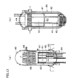
- FIGS. 12(a) and 12(b) are explanatory views of essential portions of a boiling water reactor and a pressurized water reactor, respectively, and FIGS. 13(a) and 13(b) are longitudinal sectional views showing the internal constructions of the respective reactors shown in FIG. 12.
- a fuel assembly (fuel rod) 41 for producing nuclear reaction is provided on the inside of a core shroud 42, and a control rod guide tube or a control rod driving mechanism 44 is provided below or above the fuel assembly 41.
- a core support plate 45 and a fuel support member are fixed by a core support plate 45 and a fuel support member. Further, the uppermost part of the fuel assembly 41 is fixed by an upper support plate 47.
- a steam separator 48 is provided, and further a steam dryer 49 is provided above the steam separator 48. Also, apart from a main steam-water system, an external recirculation circuit 52 in which a jet pump 50 and a recirculation pump 51 are combined is formed. Also, in the pressurized water reactor shown in FIGS. 12(b) and 13(b), hot water heated by the fuel assembly 41 is supplied to a steam generator 54 through a high temperature-side pipe 53.
- the hot water is cooled by heat exchange using the steam generator 54, and is returned into the reactor pressure vessel 40 through a low temperature-side pipe 56 via a primary coolant pump 55. Also, the low temperature-side pipe 56 and the high temperature-side pipe 53 are connected to each other via a bypass pipe 59 having an on-off valve 58.
- a stress corrosion crack is less liable to develop even in a high-temperature and pressure water environment, so that the reactor component members can be used for a long period of time. Also, if the stress corrosion crack develops, the stress corrosion crack is less liable to propagate, so that a remarkable effect can be achieved in improving safety and reliability of the nuclear power plant.
- the present invention will be explained in more detail by using an example. The present invention is not subjected to any restriction by this example.
- Table 1 gives compositions of conventional SUS 316L (comparative material 1) and 316NG (comparative material 2) widely used as a nuclear power material, and test materials 1 to 28 having chemical components (the content is expressed in percent by weight) in accordance with the present invention.
- Table 2 gives working and heat treatment conditions for the test materials given in Table 1.
- test materials 1 to 28 given in Table 1 a rectangular test piece measuring 2 mm thick, 20 mm wide, and 50 mm long was prepared, a boiling test of continuous 16 hours was conducted in conformity with JIS G0575 "Method of Copper Sulfate-Sulfuric Acid Test for Stainless Steels", and a bending test with a bend radius of 1 mm was conducted to examine the presence of cracks.
- JIS G0575 Metal Sulfate-Sulfuric Acid Test for Stainless Steels
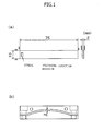
- a test piece having a shape shown in FIG. 1 was prepared from the test material given in Table 1. This test piece was subjected to a stress corrosion crack developing test of 3000 hours in an autoclave shown in FIG. 2 under the test conditions given in Table 4.
- water quality is regulated by a makeup water tank 11, and water is degassed by N 2 gas.
- high-temperature and pressure water is sent to the autoclave, which is a test vessel 19, through a preheater 15 by a high-pressure metering pump 12, and some of the high-temperature and pressure water is circulated.
- a heat exchanger 14 to which a cooler 16 is connected is provided at the front stage of the preheater 15.
- FIGS. 3 to 8 show the outline of result by plotting maximum crack length as a function of the contents of component elements (Cr, Si, N), (Cr equivalent)-(Ni equivalent), Cr equivalent / Ni equivalent, and stacking fault energy, respectively.
- FIG. 3 shows the influence of Cr content exerted on the stress corrosion crack resistance of Mo-containing austenitic stainless steel. As the Cr content increased, the stress corrosion crack resistance of Mo-containing austenitic stainless steel was improved.
- FIG. 4 shows the influence of Si content exerted on the stress corrosion crack resistance of Mo-containing austenitic stainless steel. As the Si content decreased, the stress corrosion crack length became shorter, and thus the stress corrosion crack resistance of Mo-containing austenitic stainless steel was improved.
- FIG. 5 shows the influence of N content exerted on the stress corrosion crack resistance of Mo-containing austenitic stainless steel. As the N content decreased, the stress corrosion crack length became shorter, and thus the stress corrosion crack resistance of Mo-containing austenitic stainless steel was improved.
- FIG. 6 shows the influence of (Cr equivalent)-(Ni equivalent) exerted on the stress corrosion crack resistance of Mo-containing austenitic stainless steel.
- the stress corrosion crack length became shorter, and thus the stress corrosion crack resistance of Mo-containing austenitic stainless steel was improved.
- the stress corrosion crack resistance peaked at a specific value, and if the value of (Cr equivalent)-(Ni equivalent) increased further, the stress corrosion crack resistance decreased.
- FIG. 7 shows the influence of Cr equivalent / Ni equivalent exerted on the stress corrosion crack resistance of Mo-containing austenitic stainless steel. As the ratio of Cr equivalent / Ni equivalent decreased, the stress corrosion crack length became shorter, and thus the stress corrosion crack resistance of Mo-containing austenitic stainless steel was improved.
- FIG. 8 shows the influence of stacking fault energy (a value calculated by the following equation (1)) exerted on the stress corrosion crack resistance of Mo-containing austenitic stainless steel (maximum crack length).
- SFE ( mJ / m 2 ) 25.7 + 6.2 xNi + 410 xC - 0.9 xCr - 77 xN - 13 xSi - 1.2 xMn
- the stacking fault energy is 100 (mJ/m 2 ) or higher, an especially excellent property is provided.
- Test conditions ltem Unit Test condition Corrosion potential mV 200 H 2 O 2 concentration, regulated by dissolved oxygen concentration Electric conductivity ⁇ S/cm 0.3 pH(25C°) 6.5 Temperature C° 288 Cl concentration Ppb 20
- the alloy contains 17% or more, preferably 20% or more, of Cr content, 0.01% or less of N content, and 0.1% or less, preferably 0.02% or less, of Si content in accordance with the present invention, stress corrosion crack generation shifts significantly to the long life side.
- test piece having a shape shown in FIG. 9 was prepared from the test materials given in Table 1.
- This test piece was subjected to a stress corrosion crack propagation test in an autoclave shown in FIG. 10 under the test conditions given in Table 5.
- water quality is regulated by a makeup water tank 30, and water is degassed by N 2 gas.
- high-temperature and pressure water is sent to the autoclave, which is a test vessel 35, through a preheater 34 by a high-pressure metering pump (makeup water pump) 31, and some of the high-temperature and pressure water is circulated.
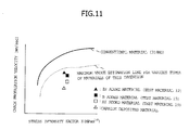
- FIG. 11 shows the results of the test materials 12, 15 and 19 and a carbide deposited material, together with the conventional material (316NG), to investigate the influence of Zr addition, B addition, Hf addition, and intergranular carbide precipitation treatment exerted on the stress corrosion crack propagation velocity of Mo-containing austenitic stainless steel. It was found that if the Zr addition, B addition, Hf addition, intergranular carbide precipitation treatment, etc. were carried out, the stress corrosion crack propagation velocity became low as compared with the conventional material, and thus the stress corrosion crack resistance of Mo-containing austenitic stainless steel was improved.
- the austenitic stainless steel in accordance with the present invention is less liable to sensitize, has high stress corrosion crack resistance, and is configured so that even if a stress corrosion crack is generated, the stress corrosion crack is less liable to propagate. Therefore, this austenitic stainless steel is especially suitable as a component material for various pipes and in-furnace structures of a nuclear reactor operated in a high-temperature and pressure water environment. From the viewpoint of safety and reliability of nuclear power plant, this austenitic stainless steel is very significant in industrial terms.
Landscapes
- Chemical & Material Sciences (AREA)
- Engineering & Computer Science (AREA)
- Mechanical Engineering (AREA)
- Materials Engineering (AREA)
- Metallurgy (AREA)
- Organic Chemistry (AREA)
- Crystallography & Structural Chemistry (AREA)
- Physics & Mathematics (AREA)
- Thermal Sciences (AREA)
- Heat Treatment Of Steel (AREA)
- Heat Treatment Of Articles (AREA)
- Heat Treatment Of Sheet Steel (AREA)
Abstract
Description
- The present invention relates to an austenitic stainless steel having high stress corrosion crack resistance, a manufacturing method for the same, and a structure using the same.
- Mo-containing low-carbon austenitic stainless steel has been used frequently as a component material for pipes and in-furnace structures of nuclear reactors because it is difficult to sensitize and has higher stress corrosion crack resistance under high-temperature and pressure water than an austenitic stainless steel containing no Mo.
However, in recent years, it has been revealed that in Mo-containing low-carbon austenitic stainless steel, stress corrosion cracks develop from regions which have been hardened by grinding or welding heat distortion. These cracks can propagate as intergranular stress corrosion cracking even if the stainless steel is not sensitized. Such a phenomenon is a new phenomenon that has not been studied conventionally. To take measures against this phenomenon, the development of a stainless steel having high stress corrosion crack resistance has become a pressing concern. - In view of the above problem, the inventors earnestly conducted studies to develop an austenitic stainless steel that is difficult to sensitize, is less liable to generate a stress corrosion crack from a region hardened by grinding or welding heat distortion, the generation of stress corrosion crack being a drawback of the Mo-containing low-carbon austenitic stainless steel, is configured so that even if a stress corrosion crack is generated, the stress corrosion crack is less liable to propagate, and can be used for a long period of time as a component material for pipes and in-furnace structures of nuclear reactors; and a manufacturing method for the austenitic stainless steel.
- To attain the above object, the inventors undertook many experiments. As a result, the following was revealed. Conventionally, in Mo-containing low-carbon austenitic stainless steel, C content has been decreased from the viewpoint of prevention of sensitization. However, since the decrease in C content lowers the strength level such as yield strength and tensile strength, about 0.08 to 0.15% of N has been added to keep a predetermined strength level. However, in the case where N forms a solid solution in the austenitic crystal matrix, the stacking fault energy of austenite is decreased, and work hardening occurs easily. Also, if heat is applied, Cr nitride deposits, and Cr content in the austenitic crystal matrix is decreased, which presumably decreases the corrosion resistance.
- To enhance the stacking fault energy of austenite, the inventors produced, on a trial basis, various types of Mo-containing low-carbon austenitic stainless steels in which N content and, in addition, Si content were changed systematically, and carried out stress corrosion crack tests in high-temperature and pressure water to make a comparison. As a result, it was found that if N content is 0.01% or lower and Si content is 0.1% or lower, the austenite matrix is less liable to be work hardened, and thus the stress corrosion crack resistance of a cold-worked material was increased significantly.
- Also, the inventors produced, on a trial basis, a Mo-containing low-carbon austenitic stainless steel in which Cr content was increased to increase the stress corrosion crack generation life and to prevent a shortage of strength such as yield strength and tensile strength caused by the decrease in N content and Si content, and Ni content was increased to prevent a shortage of stability of austenite caused by the decrease in C content and N content, and carried out stress corrosion crack tests in high-temperature and pressure water to make a comparison. As a result, it was found that the stress corrosion crack resistance was increased significantly.
- Further, it was found that in a Mo-containing low-carbon austenitic stainless steel in which Ca content and Mg content are kept at 0.001% or lower or any one of Zr, B and Hf is added, a Mo-containing low-carbon austenitic stainless steel in which (Cr equivalent) - (Ni equivalent) is controlled to -5 to +7%, and a Mo-containing low-carbon austenitic stainless steel in which Cr carbide depositing in harmonization with the austenite crystal matrix of M23C6 is deposited at the grain boundary, the intergranular stress corrosion crack propagation velocity under high-temperature and pressure water can be decreased significantly. Also, it was found that in a Mo-containing low-carbon austenitic stainless steel in which (Cr equivalent) - (Ni equivalent) is controlled to -5 to +7%, and/or the Cr equivalent / Ni equivalent is controlled to 0.7 to 1.4 as well, the intergranular stress corrosion crack propagation velocity under high-temperature and pressure water can be decreased significantly.
Furthermore, it was found that in a Mo-containing low-carbon austenitic stainless steel in which the stacking fault energy (SFE) calculated by the following equation (1):
- Therefore, the inventors obtained a knowledge that a Mo-containing low-carbon austenitic stainless steel can be obtained in which the generation of stress corrosion crack caused by hardening due to working distortion or welding heat distortion of the Mo-containing low-carbon austenitic stainless steel is prevented, and even if a stress corrosion crack is generated, the crack is less liable to propagate.
The present invention was completed from the above-described viewpoint. - That is to say, the present invention provides an austenitic stainless steel having high stress corrosion crack resistance, characterized by containing, in percent by weight, 0.030% or less C, 0.1% or less, preferably 0.02% or less, Si, 2.0% or less Mn, 0.03% or less P, 0.002% or less, preferably 0.001% or less, S, 11 to 26% Ni, 17 to 30% Cr, 3% or less Mo, and 0.01% or less N, the balance substantially being Fe and unavoidable impurities.
- Also, the present invention provides an austenitic stainless steel having high stress corrosion crack resistance, characterized by containing, in percent by weight, 0.030% or less C, 0.1% or less, preferably 0.02% or less, Si, 2.0% or less Mn, 0.03% or less P, 0.002% or less, preferably 0.001% or less, S, 11 to 26% Ni, 17 to 30% Cr, 3% or less Mo, 0.01% or less N, 0.001% or less Ca, 0.001% or less Mg, and 0.004% or less, preferably 0.001% or less, O, the balance substantially being Fe and unavoidable impurities.
- Also, the present invention provides an austenitic stainless steel having high stress corrosion crack resistance, characterized by containing, in percent by weight, 0.030% or less C, 0.1% or less, preferably 0.02% or less, Si, 2.0% or less Mn, 0.03% or less P, 0.002% or less, preferably 0.001% or less, S, 11 to 26% Ni, 17 to 30% Cr, 3% or less Mo, 0.01% or less N, 0.001% or less Ca, 0.001% or less Mg, 0.004% or less, preferably 0.001% or less, O, and 0.01% or less of any one of Zr, B and Hf, the balance substantially being Fe and unavoidable impurities.
- Further, the present invention provides the austenitic stainless steel having high stress corrosion crack resistance described in any one of the above items, characterized in that (Cr equivalent) - (Ni equivalent) is in the range of -5% to +7%. The value of (Cr equivalent) - (Ni equivalent) is preferably 0%.
- Herein, the Cr equivalent is given, for example, by

or
or the like.
Also, the Ni equivalent is given, for example, by
or
or the like. - Still further, the present invention provides the austenitic stainless steel having high stress corrosion crack resistance described in any one of the above items, characterized in that Cr equivalent / Ni equivalent is 0.7 to 1.4.
- Still further, the present invention provides the austenitic stainless steel having high stress corrosion crack resistance described in any one of the above items, characterized in that stacking fault energy (SFE) calculated by the following equation (1):

- In addition, the present invention provides a manufacturing method for a stainless steel, characterized in that a billet (steel plate, steel forging, or steel pipe) consisting of the austenitic stainless steel described in any one of the above items is subjected to solution heat treatment at a temperature of 1000 to 1150°C. Further, the present invention provides a manufacturing method for a stainless steel, characterized in that a billet (steel plate, steel forging, or steel pipe) consisting of the austenitic stainless steel described in any one of the above items is subjected to solution heat treatment at a temperature of 1000 to 1150°C, thereafter being subjected to cold working of 10 to 30%, and is then subjected to intergranular carbide precipitation heat treatment at a temperature of 600 to 800°C for 1 to 50 hours.
- All of the austenitic stainless steels described above can be used suitably, for example, especially as an austenitic stainless steel for a nuclear reactor member such as a pipe or an in-furnace structure for a nuclear reactor. Also, the stainless steel obtained by the above-described manufacturing method can also be used suitably as an austenitic stainless steel for a nuclear reactor member, namely, as a component material, such as a pipe or an in-furnace structure, for a nuclear reactor.
- As described above, the Mo-containing low-carbon austenitic stainless steel in accordance with the present invention is less liable to sensitize, has high stress corrosion crack resistance, and is configured so that even if a stress corrosion crack is generated, the stress corrosion crack is less liable to propagate. By applying this austenitic stainless steel to a pipe or an in-furnace structure of a nuclear reactor, which is a part of reactor component members, the reactor component member can be used for a long period of time.
That is to say, for the Mo-containing low-carbon austenitic stainless steel in accordance with the present invention, by making the N content and Si content proper, hardening caused by working distortion or welding heat distortion, which is a cause for stress corrosion cracking, can be restrained. Also, by making the Cr content and Ni content proper and by making the Cr equivalent and Ni equivalent proper, the stress corrosion crack generation life is increased. Further, the Ca content, Mg content, etc. for weakening the grain boundary are made proper, and further Zr, B or Hf for strengthening the grain boundary is added, or Cr carbide is deposited at the grain boundary in harmonization with the crystal matrix, by which intergranular stress corrosion cracking is made less liable to propagate. In addition, in the manufacturing method in accordance with the present invention, after subjecting to solution heat treatment at a temperature of 1000 to 1150°C, cold working of 10 to 30% is performed. The resultant product then undergoes a precipitation heat treatment at a temperature of 600 to 800°C for 1 to 50 hours, by which Cr carbide can be deposited at the grain boundary in harmonization with the crystal matrix.
Hereunder, the present invention is explained in detail with reference to an embodiment. The present invention is not subjected to any restriction by this embodiment. -
- FIG. 1(a) is a view showing a rectangular test piece prepared in example, and FIG. 1(b) is a view showing a jig used for a stress corrosion crack test, to which the test piece, whose surface has been polished with emery paper, is installed;
- FIG. 2 is a view showing a configuration of a system of a circulating autoclave for a stress corrosion crack test used in the example;
- FIG. 3 is a diagram in which stress corrosion crack lengths are plotted as a function of Cr content, in which the maximum crack lengths are plotted;
- FIG. 4 is a diagram in which stress corrosion crack lengths are plotted as a function of Si content, in which the maximum crack lengths are plotted;
- FIG. 5 is a diagram in which stress corrosion crack lengths are plotted as a function of N content, in which the maximum crack lengths are plotted;
- FIG. 6 is a diagram in which stress corrosion crack lengths are plotted as a function of (Cr equivalent) - (Ni equivalent), in which the maximum crack lengths are plotted;
- FIG. 7 is a diagram in which stress corrosion crack lengths are plotted as a function of Cr equivalent / Ni equivalent, in which the maximum crack lengths are plotted;
- FIG. 8 is a diagram in which stress corrosion crack lengths are plotted as a function of stacking fault energy, in which the maximum crack lengths are plotted;
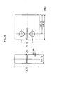
- FIG. 9 is a view showing a shape of a CT test piece for a stress corrosion crack propagation test used in the example;
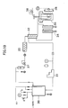
- FIG. 10 is a view showing a configuration of a system of a circulating autoclave for a stress corrosion crack propagation test used in the example;
- FIG. 11 is a graph showing the influence of Zr addition, B addition, Hf addition, and intergranular carbide precipitation treatment exerted on a stress corrosion crack propagation velocity of a Mo-containing austenitic stainless steel;
- FIG. 12(a) is an explanatory view of an essential portion of a boiling water reactor, and FIG. 12(b) is an explanatory view of an essential portion of a pressurized water reactor; and
- FIG. 13 illustrates two longitudinal sectional views showing the internal construction of the reactors shown in FIG. 12.
- An austenitic stainless steel in accordance with the present invention is one in which the contents of C, Si, Mn, P, S, Ni, Cr, Mo and N are specified in percent by weight, and the balance substantially consists of Fe and unavoidable impurities.
Now, the role of each element in the alloy is explained.
C is an element indispensable to obtain a predetermined strength and to stabilize austenite in an austenitic stainless steel. It is well known that if C is heated at temperatures of 400 to 900°C or cooled slowly in this temperature range, Cr carbide deposits at the grain boundary, and a Cr depletion layer is produced around the deposit, and sensitization such that the grain boundary becomes sensitive to corrosion occurs. To restrain the sensitization, the C content is generally set at 0.03% or lower. - If the C content is 0.03% or lower, the strength is insufficient, and also the stability of austenite is insufficient. Conventionally, therefore, N, which is an important element for obtaining the strength of austenitic stainless steel and for stabilizing austenite like C, has been added to ensure strength and stabilize austenite. However, the inventors paid attention to the fact that if the N content increases, the steel is easily hardened when working distortion or heat distortion is applied, and if the steel is affected by heat, Cr nitride deposits and the Cr content in the crystal matrix decreases, so that corrosion cracking is rather liable to occur. In the present invention, the N content was decreased by overturning the conventionally accepted practice. It was thought that it is desirable to decrease the N content to a level such that it can be decreased stably in industrial terms, and the N content was set at 0.01% or lower.
In the manufacturing process of austenitic stainless steel, Si plays an important role as a deoxidizer, and usually an austenitic stainless steel contains about 0.5% of Si. However, the inventors paid attention to the fact that the Si content of about 0.5% makes the steel easy to harden when working distortion or heat distortion is applied. In the present invention, it was thought that it is desirable to decrease the Si content as far as possible in the range such that it can be decreased stably in industrial terms, and the Si content was set at 0.1% or lower, preferably 0.02% or lower. - Cr and Mo are known as very important elements in keeping the corrosion resistance of austenitic stainless steel. However, Cr and Mo are ferrite generating elements, so that it is known that if the contents of Cr and Mo are increased too much, the stability of austenite deteriorates, and also the ductility thereof decreases, thereby deteriorating the workability. Conventionally, therefore, the contents of Cr and Mo have not been increased extremely. By contrast, the inventors decreased the contents of C, N and Si as far as possible to improve the stress corrosion crack resistance. Thereby, at the same time, the ductility of austenitic stainless steel could be increased. To cope with the problem that the stability of austenite deteriorates as a consequence of the increase in the contents of Cr and Mo and the as-much-as-possible decrease in the contents of C and N, the contents of Ni and Mn were increased, by which the inventors succeeded in maintaining the stability of austenite.
Also, a problem in that a predetermined strength level becomes insufficient due to the as-much-as-possible decrease in the contents of C and N was solved by balancing the contents of C, N, Si, Ni, Cr, Mo and Mn. - In the steel making process of austenitic stainless steel, CaF, CaO, or metal Ca is generally used for desulfurization. Ca for this purpose remains in the steel. It is known that this Ca sometimes segregates at the grain boundary, and there is a fear of decreasing the intergranular corrosion resistance. In the present invention, therefore, it is preferable that carefully selected raw materials be used, and in the steel making process of austenitic stainless steel, CaF, CaO, or metal Ca be not used as far as possible for desulfurization to prevent Ca from segregating at the grain boundary.
Also, though very rarely, Mg is sometimes added to the austenitic stainless steel to improve hot workability. However, it is known that this Mg also segregates at the grain boundary, and thus there is a fear of decreased intergranular corrosion resistance. In the present invention, therefore, it is preferable that carefully selected raw materials of Mg be used to prevent mixing of Mg as far as possible, thereby preventing the intergranular corrosion resistance from decreasing.
Zr, B and Hf are well known as elements segregating at the grain boundary, and have conventionally been said to be elements that should not be used for corrosion resistant austenitic stainless steel for nuclear power because intergranular corrosion becomes liable to occur due to the segregation of Zr, B and Hf, whereby nuclear transformation occurs and the neutron absorbing cross-sectional area is large when B and Hf receive neutron irradiation. In the present invention, however, because of the austenitic stainless steel in which the contents of C, N and Si are decreased as far as possible, even if a small amount of 0.01% or less of Zr, B and Hf is added, the stress corrosion crack propagation velocity in high-temperature and pressure water can be decreased significantly without decreasing the intergranular corrosion resistance of austenitic stainless steel. - An austenitic stainless steel is generally used in a state of being solution treated while avoiding sensitization. However, the inventors obtained knowledge that if Cr carbide depositing in harmonization with the crystal matrix is deposited at the grain boundary of austenitic stainless steel, the stress corrosion crack propagation velocity in high-temperature and pressure water can be decreased significantly. Therefore, in the manufacturing method in accordance with the present invention, to positively deposit Cr carbide depositing in harmonization with the crystal matrix, it is preferable that Cr carbide precipitation treatment at 600 to 800°C for 1 to 50 hours be performed after 10 to 30% cold working has been performed after solution heat treatment.
- The above-described austenitic stainless steel can be used suitably, for example, especially as a pipe or an in-furnace structure for a nuclear reactor. Also, the stainless steel obtained by the above-described manufacturing method can also be used suitably as a component material for a pipe or an in-furnace structure for a nuclear reactor.
FIGS. 12(a) and 12(b) are explanatory views of essential portions of a boiling water reactor and a pressurized water reactor, respectively, and FIGS. 13(a) and 13(b) are longitudinal sectional views showing the internal constructions of the respective reactors shown in FIG. 12. - In FIG. 13, in a
reactor pressure vessel 40, a fuel assembly (fuel rod) 41 for producing nuclear reaction is provided on the inside of acore shroud 42, and a control rod guide tube or a controlrod driving mechanism 44 is provided below or above thefuel assembly 41. These pieces of equipment are fixed by acore support plate 45 and a fuel support member. Further, the uppermost part of thefuel assembly 41 is fixed by anupper support plate 47. - In the boiling water reactor shown in FIGS. 12(a) and 13(a), in order to take out only steam from a gas-liquid two-phase flow boiled and generated by the
fuel assembly 41 to the upper part of the core, asteam separator 48 is provided, and further asteam dryer 49 is provided above thesteam separator 48. Also, apart from a main steam-water system, anexternal recirculation circuit 52 in which ajet pump 50 and arecirculation pump 51 are combined is formed.
Also, in the pressurized water reactor shown in FIGS. 12(b) and 13(b), hot water heated by thefuel assembly 41 is supplied to asteam generator 54 through a high temperature-side pipe 53. The hot water is cooled by heat exchange using thesteam generator 54, and is returned into thereactor pressure vessel 40 through a low temperature-side pipe 56 via aprimary coolant pump 55. Also, the low temperature-side pipe 56 and the high temperature-side pipe 53 are connected to each other via abypass pipe 59 having an on-offvalve 58. - By using the austenitic stainless steel in accordance with the present invention to manufacture the component members, such as various pipes and pumps, constituting the systems, circulation circuits, etc. or in-furnace structures such as the
core shroud 42, thecore support plate 45, theupper support plate 47, etc. of the above-described reactors, a stress corrosion crack is less liable to develop even in a high-temperature and pressure water environment, so that the reactor component members can be used for a long period of time. Also, if the stress corrosion crack develops, the stress corrosion crack is less liable to propagate, so that a remarkable effect can be achieved in improving safety and reliability of the nuclear power plant.
Hereunder, the present invention will be explained in more detail by using an example. The present invention is not subjected to any restriction by this example. - Table 1 gives compositions of conventional SUS 316L (comparative material 1) and 316NG (comparative material 2) widely used as a nuclear power material, and test materials 1 to 28 having chemical components (the content is expressed in percent by weight) in accordance with the present invention.
Table 2 gives working and heat treatment conditions for the test materials given in Table 1. -
[Table 1] Table 1 Target chemical composition, melting method, and working and heat treatment method of test melted material Material No. Purpose Chemical component (Wt%) Ni equivalent Cr equivalent C N Si Mn P S Ni Cr Mo Others Comparative example 1 Conventional material (SUS316L) ≦ 0.030 - 5 1.0 ≦ 2.0 ≦ 0.045 ≦ 0.030 from 12.0 to 15.0 from 16.00 to 18.00 from 2.00 to 3.00 - Comparative example 2 Conventional material (316NG) ≦ 0.030 from 0.08 to 0.15 ≦ 1.0 ≦ 2.0 ≦ 0.045 ≦ 0.030 from 12.0 to 15.0 from 16.00 to 18.00 from 2.00 to 3.00 - Test material 1 SUS316L test material 0.0191 0.03 0.52 0.83 0.023 0.002 12.4 16.4 2.32 14.3 19.5 Test material 2 316NG test material 0.0192 0.095 0.53 0.84 0.024 0.001 12.5 16.5 2.31 16.3 19.6 Test material 3 Influence of Cr content and SFE 0.0191 0.087 0.51 0.81 0.026 0.001 12.3 18.1 2.33 15.9 21.2 Test material 4 Influence of Cr content and SFE 0.0194 0.101 0.54 0.82 0.025 0.001 12.2 20.2 2.34 16.2 23.4 Test material 5 Influence of Cr content and SFE 0.0193 0.095 0.55 0.83 0.023 0.001 12.4 25.3 2.30 16.2 28.4 Test material 6 Influence of Cr equivalent, Ni equivalent, and SFE 0.0195 0.102 0.52 0.88 0.022 0.002 19.1 25.2 2.31 23.2 28.3 Test material 7 Influence of Cr equivalent, Ni equivalent, 0.0193 0.101 0.53 0.82 0.021 0.001 15.2 23.4 2.32 19.2 26.5 and SFE Test material 8 Influence of Si content and SFE 0.0192 0.102 0.22 0.81 0.025 0.001 12.5 16.5 2.33 16.5 19.2 Test material 9 Influence of Si content and SFE 0.0194 0.101 0.10 0.83 0.022 0.002 12.4 16.4 2.34 16.4 18.9 Test material 10 Influence of Si content and SFE 0.0195 0.101 ≦ 0.02 0.82 0.024 0.001 12.3 16.7 2.32 16.3 19.1 Test material 11 Influence of trace element 0.0193 0.095 0.53 0.81 0.026 0.002 12.2 16.8 2.31 0.02Mg 16.0 19.9 Test material 12 Influence of trace element 0.0194 0.101 0.52 0.82 0.027 0.001 12.5 16.1 2.33 0.009Zr 16.5 19.2 Test material 13 Influence of trace element 0.0192 0.102 0.51 0.84 0.026 0.002 12.5 16.3 2.32 0.005Ca 16.6 19.4 Test material 14 Influence of trace element 0.0193 0.103 0.53 0.82 0.025 0.001 12.6 16.4 2.31 0.0060 16.7 19.5 Test material 15 Influence of trace element 0.0192 0.102 0.52 0.81 0.022 0.002 12.7 16.5 2.33 0.009B 16.7 19.6 Test material 16 Influence of trace element 0.0191 0.101 0.54 0.83 0.023 0.001 12.8 16.7 2.32 0.20Al 16.8 19.8 Test material 17 Influence of trace element 0.0194 0.102 0.52 0.81 0.026 0.002 12.9 16.4 2.33 0.20Ti 16.9 19.5 Test material 18 Influence of trace element 0.0193 0.103 0.53 0.83 0.024 0.001 12.3 16.5 2.31 0.20V 16.4 19.6 Test material 19 Influence of trace element 0.0192 0.095 0.51 0.85 0.025 0.002 12.5 16.3 2.34 0.009Hf 16.4 19.4 Test material 20 Influence of Ni equivalent, Cr equivalent, and SFE 0.0191 0.098 0.50 0.82 0.026 0.001 15.0 16.4 2.32 18.9 19.5 Test material 21 Influence of Ni equivalent, 0.0193 0.003 ≦ 0.02 0.81 0.025 0.002 11.0 18.2 2.31 12.1 20.5 Cr equivalent, and SFE Test material 22 Influence of Ni equivalent, Cr equivalent, and SFE 0.0194 0.101 0.52 2.0 0.023 0.001 10.1 16.3 2.33 14.7 19.4 Test material 23 Influence of Ni equivalent, Cr equivalent, and SFE 0.0191 0.102 0.53 ≦ 0.03 0.022 0.002 12.5 16.4 2.32 16.1 19.5 Test material 24 Influence of Mo content and SFE 0.0193 0.102 0.51 0.83 0.024 0.001 12.6 16.5 1.01 16.7 18.3 Test material 25 Influence of Ni equivalent, Cr equivalent Mo equivalent, and SFE 0.0192 0.003 ≦ 0.02 0.81 0.025 0.001 15.1 23.2 1.03 16.2 24.3 Test material 26 Influence of Ni equivalent, Cr equivalent, and SFE 0.0191 0.003 ≦ 0.02 0.85 0.026 0.001 25.2 23.1 2.34 26.3 25.5 Test material 27 Influence of Ni equivalent, Cr equivalent, and SFE 0.0194 0.003 ≦ 0.02 0.82 0.028 0.001 20.1 25.1 2.33 21.2 27.5 Test material 28 Influence of SFE 0.0194 0.003 0.52 0.81 0.027 0.001 12.5 16.4 2.32 13.6 19.5 - [Table 2] Working and heat treatment conditions

- For the test materials 1 to 28 given in Table 1, a rectangular test piece measuring 2 mm thick, 20 mm wide, and 50 mm long was prepared, a boiling test of continuous 16 hours was conducted in conformity with JIS G0575 "Method of Copper Sulfate-Sulfuric Acid Test for Stainless Steels", and a bending test with a bend radius of 1 mm was conducted to examine the presence of cracks. The results are given in Table 3.
-
[Table 3] Bending test results after copper sulfate-sulfuric acid test Material No. Bending tes result Material No. Bending tes result Material No. Bending tes result Material No. Bending tes result Test material 1 O Test material 8 O Test material 15 O Test material 22 O Test material 2 O Test material 9 O Test material 16 O Test material 23 O Test material 3 O Test material 10 O Test material 17 O Test material 24 O Test material 4 O Test material 11 O Test material 18 O Test material 25 O Test material 5 O Test material 12 O Test material 19 O Test material 26 O Test material 6 O Test material 13 O Test material 20 O Test material 27 O Test material 7 O Test material 14 O Test material 21 O Test material 28 O ○: No crack - A test piece having a shape shown in FIG. 1 was prepared from the test material given in Table 1. This test piece was subjected to a stress corrosion crack developing test of 3000 hours in an autoclave shown in FIG. 2 under the test conditions given in Table 4. In the circulating autoclave for stress corrosion crack test shown in FIG. 2, water quality is regulated by a
makeup water tank 11, and water is degassed by N2 gas. Thereafter, high-temperature and pressure water is sent to the autoclave, which is atest vessel 19, through apreheater 15 by a high-pressure metering pump 12, and some of the high-temperature and pressure water is circulated. At the front stage of thepreheater 15, aheat exchanger 14 to which a cooler 16 is connected is provided. Thetest vessel 19 is covered with anelectric furnace 18.
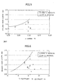
FIGS. 3 to 8 show the outline of result by plotting maximum crack length as a function of the contents of component elements (Cr, Si, N), (Cr equivalent)-(Ni equivalent), Cr equivalent / Ni equivalent, and stacking fault energy, respectively. - FIG. 3 shows the influence of Cr content exerted on the stress corrosion crack resistance of Mo-containing austenitic stainless steel. As the Cr content increased, the stress corrosion crack resistance of Mo-containing austenitic stainless steel was improved.
- FIG. 4 shows the influence of Si content exerted on the stress corrosion crack resistance of Mo-containing austenitic stainless steel. As the Si content decreased, the stress corrosion crack length became shorter, and thus the stress corrosion crack resistance of Mo-containing austenitic stainless steel was improved.
- FIG. 5 shows the influence of N content exerted on the stress corrosion crack resistance of Mo-containing austenitic stainless steel. As the N content decreased, the stress corrosion crack length became shorter, and thus the stress corrosion crack resistance of Mo-containing austenitic stainless steel was improved.
- FIG. 6 shows the influence of (Cr equivalent)-(Ni equivalent) exerted on the stress corrosion crack resistance of Mo-containing austenitic stainless steel. As the value of (Cr equivalent)-(Ni equivalent) increased, the stress corrosion crack length became shorter, and thus the stress corrosion crack resistance of Mo-containing austenitic stainless steel was improved. However, the stress corrosion crack resistance peaked at a specific value, and if the value of (Cr equivalent)-(Ni equivalent) increased further, the stress corrosion crack resistance decreased.
- FIG. 7 shows the influence of Cr equivalent / Ni equivalent exerted on the stress corrosion crack resistance of Mo-containing austenitic stainless steel. As the ratio of Cr equivalent / Ni equivalent decreased, the stress corrosion crack length became shorter, and thus the stress corrosion crack resistance of Mo-containing austenitic stainless steel was improved.
- FIG. 8 shows the influence of stacking fault energy (a value calculated by the following equation (1)) exerted on the stress corrosion crack resistance of Mo-containing austenitic stainless steel (maximum crack length).

As the stacking fault energy increased, the stress corrosion crack length became shorter, and thus the stress corrosion crack resistance of Mo-containing austenitic stainless steel was improved. In particular, it was found that when the stacking fault energy is 100 (mJ/m2) or higher, an especially excellent property is provided. -
[Table 4] Test conditions ltem Unit Test condition Corrosion potential mV 200 H2O2 concentration, regulated by dissolved oxygen concentration Electric conductivity µ S/cm 0.3 pH(25C°) 6.5 Temperature C° 288 Cl concentration Ppb 20 - It was found that if the alloy contains 17% or more, preferably 20% or more, of Cr content, 0.01% or less of N content, and 0.1% or less, preferably 0.02% or less, of Si content in accordance with the present invention, stress corrosion crack generation shifts significantly to the long life side.
- Furthermore, a test piece having a shape shown in FIG. 9 was prepared from the test materials given in Table 1. This test piece was subjected to a stress corrosion crack propagation test in an autoclave shown in FIG. 10 under the test conditions given in Table 5. In the circulating autoclave for stress corrosion crack propagation test shown in FIG. 10, water quality is regulated by a
makeup water tank 30, and water is degassed by N2 gas. Thereafter, high-temperature and pressure water is sent to the autoclave, which is atest vessel 35, through apreheater 34 by a high-pressure metering pump (makeup water pump) 31, and some of the high-temperature and pressure water is circulated. At the front stage of thepreheater 34, aheat exchanger 32 to which a cooler 33 is connected is provided. In the vicinity of thetest vessel 35, aheater 36 is provided.
FIG. 11 shows the results of thetest materials -
[Table 5] Item Unit Test condition Water quality condition Corrosion poteritial mV 200 H2O2 concentration. regulated by dissolved oxygen concentration Electric conductivity µ S/cm 0.3 pH(25C°) 6.5 Temperature °C 288 Cl concentration Ppb 20 H2O2 concentration ppm stress load condition Waveform Trapezoidal waveform Load relieving ratio 30%(R=0.7) holding time at maximum load stress hour 30 - The austenitic stainless steel in accordance with the present invention is less liable to sensitize, has high stress corrosion crack resistance, and is configured so that even if a stress corrosion crack is generated, the stress corrosion crack is less liable to propagate. Therefore, this austenitic stainless steel is especially suitable as a component material for various pipes and in-furnace structures of a nuclear reactor operated in a high-temperature and pressure water environment. From the viewpoint of safety and reliability of nuclear power plant, this austenitic stainless steel is very significant in industrial terms.
Claims (12)
- An austenitic stainless steel having high stress corrosion crack resistance, characterized by containing, in percent by weight,
0.030% or less C,
0.1% or less Si,
2.0% or less Mn,
0.03% or less P,
0.002% or less S,
11 to 26% Ni,
17 to 30% Cr,
3% or less Mo, and
0.01% or less N,
the balance substantially being Fe and unavoidable impurities. - An austenitic stainless steel having high stress corrosion crack resistance, characterized by containing, in percent by weight, 0.030% or less C,
0.1% or less Si,
2.0% or less Mn,
0.03% or less P,
0.002% or less S,
11 to 26% Ni,
17 to 30% Cr,
3% or less Mo,
0.01% or less N,
0.001% or less Ca,
0.001% or less Mg, and
0.004% or less O,
the balance substantially being Fe and unavoidable impurities. - An austenitic stainless steel having high stress corrosion crack resistance, characterized by containing, in percent by weight, 0.030% or less C,
0.1% or less Si,
2.0% or less Mn,
0.03% or less P,
0.002% or less S,
11 to 26% Ni,
17 to 30% Cr,
3% or less Mo,
0.01% or less N,
0.001% or less Ca,
0.001% or less Mg,
0.004% or less O, and
0.01% or less of any one of Zr, B and Hf,
the balance substantially being Fe and unavoidable impurities. - The austenitic stainless steel having high stress corrosion crack resistance according to any one of claims 1 to 3, characterized in that
(Cr equivalent) - (Ni equivalent) is in the range of -5% to +7%. - The austenitic stainless steel having high stress corrosion crack resistance according to any one of claims 1 to 4, characterized in that
Cr equivalent / Ni equivalent is 0.7 to 1.4. - The austenitic stainless steel having high stress corrosion crack resistance according to any one of claims 1 to 5, characterized in that
stacking fault energy (SFE) calculated by the following equation (1):
- A manufacturing method for a stainless steel, characterized in that
a billet consisting of the austenitic stainless steel according to any one of claims 1 to 6 is subjected to solution heat treatment at a temperature of 1000 to 1150°C. - A manufacturing method for a stainless steel, characterized in that
a billet consisting of the austenitic stainless steel according to any one of claims 1 to 6 is subjected to solution heat treatment at a temperature of 1000 to 1150°C, thereafter being subjected to cold working of 10 to 30%, and is then subjected to intergranular carbide precipitation treatment at a temperature of 600 to 800°C for 1 to 50 hours. - A structure in a nuclear reactor, characterized by being formed of the austenitic stainless steel according to any one of claims 1 to 6.
- A pipe for a nuclear reactor, characterized by being formed of the austenitic stainless steel according to any one of claims 1 to 6.
- A structure in a nuclear reactor, characterized by being formed of the stainless steel obtained by the manufacturing method according to claim 7 or 8.
- A pipe for a nuclear reactor, characterized by being formed of the stainless steel obtained by the manufacturing method according to claim 7 or 8.
Applications Claiming Priority (2)
| Application Number | Priority Date | Filing Date | Title |
|---|---|---|---|
| JP2004004928 | 2004-01-13 | ||
| PCT/JP2005/000274 WO2005068674A1 (en) | 2004-01-13 | 2005-01-13 | Austenitic stainless steel, method for producing same and structure using same |
Publications (2)
| Publication Number | Publication Date |
|---|---|
| EP1715071A1 true EP1715071A1 (en) | 2006-10-25 |
| EP1715071A4 EP1715071A4 (en) | 2007-08-29 |
Family
ID=34792081
Family Applications (1)
| Application Number | Title | Priority Date | Filing Date |
|---|---|---|---|
| EP05703513A Withdrawn EP1715071A4 (en) | 2004-01-13 | 2005-01-13 | AUSTENITIC STAINLESS STEEL, PROCESS FOR PRODUCING THE SAME, AND STRUCTURE COMPRISING THE SAME |
Country Status (8)
| Country | Link |
|---|---|
| US (1) | US8172959B2 (en) |
| EP (1) | EP1715071A4 (en) |
| JP (1) | JP4616772B2 (en) |
| KR (1) | KR100848020B1 (en) |
| CN (1) | CN1942596B (en) |
| MX (1) | MXPA06008027A (en) |
| TW (1) | TWI289606B (en) |
| WO (1) | WO2005068674A1 (en) |
Cited By (3)
| Publication number | Priority date | Publication date | Assignee | Title |
|---|---|---|---|---|
| WO2013045661A1 (en) * | 2011-09-30 | 2013-04-04 | Areva Np | Process for producing, from a preform made of austenitic stainless steel with a low carbon content, a wear-resistant and corrosion-resistant cladding for a nuclear reactor, corresponding cladding and corresponding control cluster |
| EP2865771A4 (en) * | 2012-06-20 | 2016-03-09 | Nippon Steel & Sumitomo Metal Corp | TUBE BASED ON AUSTENITIC ALLOY |
| RU2631067C1 (en) * | 2016-10-28 | 2017-09-18 | Федеральное государственное автономное образовательное учреждение высшего образования "Белгородский государственный национальный исследовательский университет" (НИУ "БелГУ") | Method for producing sheets from cold-resistant high-strength austenitic steel |
Families Citing this family (29)
| Publication number | Priority date | Publication date | Assignee | Title |
|---|---|---|---|---|
| JP5216226B2 (en) * | 2006-03-14 | 2013-06-19 | 古河電池株式会社 | Lead pipe |
| SE531379C2 (en) * | 2006-06-08 | 2009-03-17 | Nord Lock Ab | Method for hardening and coating steel washers for locking and steel lock washer |
| JP2009079240A (en) * | 2007-09-25 | 2009-04-16 | Tohoku Univ | Austenitic stainless steel and its manufacturing method, reactor internal structure and piping |
| KR20110128924A (en) * | 2009-03-27 | 2011-11-30 | 수미도모 메탈 인더스트리즈, 리미티드 | Austenitic Stainless Steel |
| CN101994068B (en) * | 2009-08-25 | 2012-12-26 | 宝山钢铁股份有限公司 | Austenitic stainless steel plate |
| US8805614B2 (en) * | 2010-08-31 | 2014-08-12 | Schlumberger Technology Corporation | Downhole sample analysis method |
| CN102605285B (en) * | 2011-01-25 | 2014-05-07 | 宝山钢铁股份有限公司 | Austenitic stainless steel and method for manufacturing same |
| SI2714955T1 (en) * | 2011-05-26 | 2021-11-30 | N'Genius Technology Limited | Austenitic stainless steel |
| CN102747296B (en) * | 2012-06-06 | 2014-01-01 | 兰州理工大学 | Austenitic stainless steel and its preparation method |
| CN103194690A (en) * | 2013-04-15 | 2013-07-10 | 丹阳恒庆复合材料科技有限公司 | Stainless steel with intergranular corrosion resistance and preparation method thereof |
| CN104046913B (en) * | 2013-11-28 | 2016-12-21 | 攀钢集团攀枝花钢铁研究院有限公司 | The application of stainless steel material and a kind of flue and preparation method thereof |
| JP6186658B2 (en) * | 2013-11-29 | 2017-08-30 | 三菱重工業株式会社 | Welded structure design method and welded structure manufacturing method |
| CN104032233B (en) * | 2014-05-27 | 2016-09-14 | 中国核动力研究设计院 | A kind of austenitic stainless steel and manufacturing process thereof |
| CN105112811B (en) * | 2015-09-07 | 2017-03-22 | 中国科学院合肥物质科学研究院 | Austenitic stainless steel jacketing pipe for lead-bismuth fast reactor and preparation method of austenitic stainless steel jacketing pipe |
| KR101680534B1 (en) * | 2015-09-22 | 2016-12-12 | 한국원자력연구원 | Apparatus and method for reducing iascc of structure in nuclear reactor |
| CN105177262B (en) * | 2015-09-25 | 2018-06-19 | 安阳工学院 | A kind of method for improving special grain boundary ratio in precipitation strength austenitic heat-resistance steel |
| CN105304189A (en) * | 2015-12-04 | 2016-02-03 | 江苏亨通电力特种导线有限公司 | Stainless-steel-coated carbon fiber single conductor wire and corresponding production technology thereof |
| ES2925948T3 (en) | 2015-12-14 | 2022-10-20 | Swagelok Co | High-alloy stainless steel forgings made without solution annealing |
| CN105935861B (en) * | 2016-05-26 | 2018-01-23 | 沈阳科金特种材料有限公司 | A kind of preparation method of nuclear power high-strength plasticity austenitic stainless steel cap screw forging |
| CN108220822A (en) * | 2018-01-15 | 2018-06-29 | 宿州博斯特精密铸造有限公司 | A kind of HIGH STRENGTH NON-MAGNETIC STAINLESS STEEL |
| CN109649367A (en) * | 2018-12-05 | 2019-04-19 | 中车长江车辆有限公司 | The preparation method and vehicle of a kind of brake pipe, brake pipe |
| KR102641260B1 (en) * | 2019-05-31 | 2024-02-29 | 닛폰세이테츠 가부시키가이샤 | Austenitic stainless steel |
| CN110484836B (en) * | 2019-09-24 | 2021-01-05 | 南京佑天金属科技有限公司 | Hafnium zirconium titanium molybdenum reinforced austenitic stainless steel and preparation method thereof |
| CN111575591A (en) * | 2020-06-24 | 2020-08-25 | 中国石油化工股份有限公司 | A corrosion-resistant stainless steel material |
| CN113430455B (en) * | 2021-05-31 | 2022-05-17 | 中国科学院金属研究所 | A kind of high-strength austenitic stainless steel resistant to liquid lead and bismuth corrosion and preparation method thereof |
| CN116479319B (en) * | 2022-01-13 | 2025-02-18 | 宝山钢铁股份有限公司 | A high-strength pipe resistant to ozone corrosion and a manufacturing method thereof |
| CN116516244A (en) * | 2022-01-21 | 2023-08-01 | 宝山钢铁股份有限公司 | Sodium hydroxide corrosion-resistant high-strength pipeline and manufacturing method thereof |
| CN116377321B (en) * | 2023-03-24 | 2024-12-13 | 鞍钢股份有限公司 | A ferrite-free ultra-pure urea-grade austenitic stainless steel plate and preparation method thereof |
| CN116732437A (en) * | 2023-06-14 | 2023-09-12 | 北京科技大学 | Sensitization-resistant and stress corrosion-resistant stainless steel, and preparation method and application thereof |
Family Cites Families (17)
| Publication number | Priority date | Publication date | Assignee | Title |
|---|---|---|---|---|
| US3563728A (en) * | 1968-03-12 | 1971-02-16 | Westinghouse Electric Corp | Austenitic stainless steels for use in nuclear reactors |
| JPS5469516A (en) | 1977-11-14 | 1979-06-04 | Hitachi Ltd | Heat treating method for austenitic stainless steel to prevent stress corrosion cracking |
| JPS5931822A (en) * | 1982-08-12 | 1984-02-21 | Kobe Steel Ltd | Production of austenitic stainless steel for cladding pipe of fast breeder reactor |
| US4643767A (en) * | 1984-11-19 | 1987-02-17 | Cabot Corporation | Nuclear grade steels |
| US4720435A (en) | 1984-11-19 | 1988-01-19 | Haynes International, Inc. | Nuclear grade steel articles |
| JPH0297651A (en) | 1988-09-30 | 1990-04-10 | Aichi Steel Works Ltd | Free cutting austenitic stainless steel excellent in controlled rollability and its production |
| JPH03267350A (en) | 1990-03-16 | 1991-11-28 | Hitachi Ltd | Irradiation resistant austenitic stainless steel |
| JP3001614B2 (en) | 1990-07-11 | 2000-01-24 | 日新製鋼株式会社 | Extremely soft austenitic stainless steel |
| JP3217088B2 (en) * | 1991-07-26 | 2001-10-09 | 三桜工業株式会社 | Stainless steel multiple winding pipe |
| JPH0559494A (en) | 1991-09-03 | 1993-03-09 | Hitachi Ltd | Austenitic stainless steel excellent in radiation induced segregation resistance |
| JPH06122946A (en) | 1992-08-25 | 1994-05-06 | Nippon Steel Corp | Austenitic stainless steel with excellent intergranular corrosion resistance |
| KR950009223B1 (en) * | 1993-08-25 | 1995-08-18 | 포항종합제철주식회사 | Austenitic stainless steel with excellent press formability, hot workability and high temperature oxidation resistance |
| WO1995011321A1 (en) | 1993-10-20 | 1995-04-27 | Sumitomo Metal Industries, Ltd. | Stainless steel for high-purity gas |
| JPH07209485A (en) | 1994-01-18 | 1995-08-11 | Hitachi Ltd | Reactor and fusion reactor |
| JP2991050B2 (en) * | 1994-08-23 | 1999-12-20 | 住友金属工業株式会社 | Stainless steel pipe for high purity gas |
| JPH09125205A (en) * | 1995-09-01 | 1997-05-13 | Mitsubishi Heavy Ind Ltd | Neutron-resistant irradiation deterioration High Ni austenitic stainless steel |
| JPH10317104A (en) | 1997-05-16 | 1998-12-02 | Nippon Steel Corp | Austenitic stainless steel excellent in intergranular stress corrosion cracking resistance and method for producing the same |
-
2005
- 2005-01-13 CN CN200580007157.6A patent/CN1942596B/en not_active Expired - Lifetime
- 2005-01-13 EP EP05703513A patent/EP1715071A4/en not_active Withdrawn
- 2005-01-13 KR KR1020067015424A patent/KR100848020B1/en not_active Expired - Lifetime
- 2005-01-13 WO PCT/JP2005/000274 patent/WO2005068674A1/en not_active Ceased
- 2005-01-13 JP JP2005517050A patent/JP4616772B2/en not_active Expired - Fee Related
- 2005-01-13 MX MXPA06008027A patent/MXPA06008027A/en active IP Right Grant
- 2005-01-13 TW TW094101023A patent/TWI289606B/en not_active IP Right Cessation
- 2005-01-13 US US10/585,885 patent/US8172959B2/en active Active
Cited By (8)
| Publication number | Priority date | Publication date | Assignee | Title |
|---|---|---|---|---|
| WO2013045661A1 (en) * | 2011-09-30 | 2013-04-04 | Areva Np | Process for producing, from a preform made of austenitic stainless steel with a low carbon content, a wear-resistant and corrosion-resistant cladding for a nuclear reactor, corresponding cladding and corresponding control cluster |
| FR2980804A1 (en) * | 2011-09-30 | 2013-04-05 | Areva Np | PROCESS FOR MAKING A LOW CARBON AUSTENITIC STAINLESS STEEL DRAFT OF A WEAR AND CORROSION-RESISTANT SHEATH FOR CORRESPONDING NUCLEAR REACTOR, SHEATH AND CLUSTER |
| CN103958703A (en) * | 2011-09-30 | 2014-07-30 | 阿海珐核能公司 | Process for producing, from a preform made of austenitic stainless steel with a low carbon content, a wear-resistant and corrosion-resistant cladding for a nuclear reactor, corresponding cladding and corresponding control cluster |
| CN103958703B (en) * | 2011-09-30 | 2016-06-22 | 阿海珐核能公司 | The prepreg manufacture being made up of the austenitic stainless steel of low carbon content is for the wear-resistant of nuclear reactor and the method for corrosion resistant covering, corresponding covering and corresponding controls bunch |
| US9914986B2 (en) | 2011-09-30 | 2018-03-13 | Areva Np | Method for producing, from a preform made of austenitic stainless steel with a low carbon content, a wear-resistant and corrosion-resistant cladding for a nuclear reactor, corresponding cladding and corresponding control cluster |
| EP2865771A4 (en) * | 2012-06-20 | 2016-03-09 | Nippon Steel & Sumitomo Metal Corp | TUBE BASED ON AUSTENITIC ALLOY |
| US9859026B2 (en) | 2012-06-20 | 2018-01-02 | Nippon Steel & Sumitomo Metal Corporation | Austenitic alloy tube |
| RU2631067C1 (en) * | 2016-10-28 | 2017-09-18 | Федеральное государственное автономное образовательное учреждение высшего образования "Белгородский государственный национальный исследовательский университет" (НИУ "БелГУ") | Method for producing sheets from cold-resistant high-strength austenitic steel |
Also Published As
| Publication number | Publication date |
|---|---|
| US8172959B2 (en) | 2012-05-08 |
| TW200533766A (en) | 2005-10-16 |
| EP1715071A4 (en) | 2007-08-29 |
| KR100848020B1 (en) | 2008-07-23 |
| KR20070008563A (en) | 2007-01-17 |
| CN1942596B (en) | 2010-11-17 |
| TWI289606B (en) | 2007-11-11 |
| CN1942596A (en) | 2007-04-04 |
| JP4616772B2 (en) | 2011-01-19 |
| JPWO2005068674A1 (en) | 2007-12-27 |
| MXPA06008027A (en) | 2007-03-07 |
| US20080308198A1 (en) | 2008-12-18 |
| WO2005068674A1 (en) | 2005-07-28 |
Similar Documents
| Publication | Publication Date | Title |
|---|---|---|
| US8172959B2 (en) | Austenitic stainless steel, manufacturing method for the same, and structure using the same | |
| EP0386673B1 (en) | High-strength high-Cr steel with excellent toughness and oxidation resistance | |
| US4975131A (en) | High strength hot worked stainless steel | |
| WO2003044238A1 (en) | Super-austenitic stainless steel | |
| JP2009161802A (en) | High corrosion resistance austenitic stainless steel, and nuclear power plant, welded joint and structural member constructed using the stainless steel | |
| EP0515112B1 (en) | Corrosion resistant high chromium stainless steel alloy and method of reducing stress corrosion cracking | |
| JP2000054026A (en) | Method for producing pressure vessel used in the presence of hydrogen sulfide, and steel therefor | |
| KR20190122755A (en) | Low temperature nickel-containing steel sheet and low temperature tank using the same | |
| JP2009079240A (en) | Austenitic stainless steel and its manufacturing method, reactor internal structure and piping | |
| EP2803741B1 (en) | Method of post weld heat treatment of a low alloy steel pipe | |
| KR20220147727A (en) | Steel plate and its manufacturing method | |
| JP2014005509A (en) | Highly corrosion-resistant austenitic stainless steel and weld joint structure | |
| EP0241553B1 (en) | High strength stainless steel, and process for its production | |
| CN109504826B (en) | A kind of high-strength and high-corrosion-resistant stainless steel containing copper and vanadium and preparation method thereof | |
| JP7011987B2 (en) | Ni-based weld metal and welded structure | |
| JPH057455B2 (en) | ||
| Karzov et al. | Materials science aspects of operational safety enhancement of advanced VVER based on vessel steel improvements | |
| JP3141646B2 (en) | Austenitic stainless steel for nitric acid containing environment | |
| US10550451B2 (en) | Ni-based alloy pipe or tube for nuclear power | |
| JP2006144068A (en) | Austenitic stainless steel | |
| Yonezawa et al. | Improvement of IASCC Resistance for Austenitic Stainless Steels in PWR Environment | |
| JPS6039118A (en) | Manufacture of austenitic stainless steel containing boron and having superior resistance to intergranular corrosion and intergranular stress corrosion cracking | |
| JPH06184631A (en) | Method for producing nitric acid resistant austenitic stainless steel | |
| JPH06271933A (en) | Production of mo-containing austenitic stainless steel excellent in nitric acid resistance | |
| JPH02175842A (en) | Stainless steel for unclear reactor core equipment and its production |
Legal Events
| Date | Code | Title | Description |
|---|---|---|---|
| PUAI | Public reference made under article 153(3) epc to a published international application that has entered the european phase |
Free format text: ORIGINAL CODE: 0009012 |
|
| 17P | Request for examination filed |
Effective date: 20060712 |
|
| AK | Designated contracting states |
Kind code of ref document: A1 Designated state(s): CH DE ES FI LI SE |
|
| RIN1 | Information on inventor provided before grant (corrected) |
Inventor name: SAKAGUCHI, YASUHIRO,MITSUBISHI HEAVY IND. LTD. Inventor name: YONEZAWA, TOSHIO,KORYO ENGINEERING CO., LTD. Inventor name: KANASAKI, HIROSHI,MITSUBISHI HEAVY IND. LTD. Inventor name: HIRANUMA, NAOKI,TOKYO ELECTRIC POWER CO. INC. Inventor name: TAKAMORI, KENROU,TOKYO ELECTRIC POWER CO. INC. Inventor name: OOKI, SUGURU,TOKYO ELECTRIC POWER CO. INC. Inventor name: MIMAKI, HIDEHITO,MITSUBISHI HEAVY IND. LTD. Inventor name: ANAHARA, NAOKI,TOKYO ELECTRIC POWER CO. INC. Inventor name: IWAMURA, TOSHIHIKO,MITSUBISHI HEAVY IND. LTD. Inventor name: .TANEIKE, MASAKI,MITSUBISHI HEAVY IND. LTD. Inventor name: SUZUKI, SHUNICHI,TOKYO ELECTRIC POWER CO. INC. |
|
| DAX | Request for extension of the european patent (deleted) | ||
| RBV | Designated contracting states (corrected) |
Designated state(s): CH DE ES FI LI SE |
|
| A4 | Supplementary search report drawn up and despatched |
Effective date: 20070801 |
|
| 17Q | First examination report despatched |
Effective date: 20110201 |
|
| GRAP | Despatch of communication of intention to grant a patent |
Free format text: ORIGINAL CODE: EPIDOSNIGR1 |
|
| INTG | Intention to grant announced |
Effective date: 20171009 |
|
| RIN1 | Information on inventor provided before grant (corrected) |
Inventor name: SUZUKI, SHUNICHI, TOKYO ELECTRIC POWER CO. INC. Inventor name: OOKI, SUGURU, TOKYO ELECTRIC POWER CO. INC. Inventor name: MIMAKI, HIDEHITO, MITSUBISHI HEAVY IND. LTD. Inventor name: IWAMURA, TOSHIHIKO, MITSUBISHI HEAVY IND. LTD. Inventor name: TANEIKE, MASAKI, MITSUBISHI HEAVY IND. LTD. Inventor name: ANAHARA, NAOKI, TOKYO ELECTRIC POWER CO. INC. Inventor name: SAKAGUCHI, YASUHIRO, MITSUBISHI HEAVY IND. LTD. Inventor name: YONEZAWA, TOSHIO, KORYO ENGINEERING CO., LTD. Inventor name: KANASAKI, HIROSHI, MITSUBISHI HEAVY IND. LTD. Inventor name: TAKAMORI, KENROU, TOKYO ELECTRIC POWER CO. INC. Inventor name: HIRANUMA, NAOKI, TOKYO ELECTRIC POWER CO. INC. |
|
| STAA | Information on the status of an ep patent application or granted ep patent |
Free format text: STATUS: THE APPLICATION IS DEEMED TO BE WITHDRAWN |
|
| 18D | Application deemed to be withdrawn |
Effective date: 20180220 |