EP1714552B1 - Vorrichtung zur Stützung eines Tierbeines - Google Patents
Vorrichtung zur Stützung eines Tierbeines Download PDFInfo
- Publication number
- EP1714552B1 EP1714552B1 EP06075910A EP06075910A EP1714552B1 EP 1714552 B1 EP1714552 B1 EP 1714552B1 EP 06075910 A EP06075910 A EP 06075910A EP 06075910 A EP06075910 A EP 06075910A EP 1714552 B1 EP1714552 B1 EP 1714552B1
- Authority
- EP
- European Patent Office
- Prior art keywords
- spool
- blocking
- releasing
- leg
- unwinding
- Prior art date
- Legal status (The legal status is an assumption and is not a legal conclusion. Google has not performed a legal analysis and makes no representation as to the accuracy of the status listed.)
- Not-in-force
Links
- 230000000903 blocking effect Effects 0.000 claims abstract description 40
- 230000003100 immobilizing effect Effects 0.000 claims abstract description 11
- 238000004804 winding Methods 0.000 claims abstract description 10
- 230000008878 coupling Effects 0.000 claims description 31
- 238000010168 coupling process Methods 0.000 claims description 31
- 238000005859 coupling reaction Methods 0.000 claims description 31
- 238000010276 construction Methods 0.000 claims description 5
- 230000009849 deactivation Effects 0.000 claims 1
- 238000007689 inspection Methods 0.000 abstract 1
- 230000006378 damage Effects 0.000 description 3
- 210000001364 upper extremity Anatomy 0.000 description 2
- 230000001133 acceleration Effects 0.000 description 1
- 230000003213 activating effect Effects 0.000 description 1
- 238000005352 clarification Methods 0.000 description 1
- 210000000078 claw Anatomy 0.000 description 1
- 230000036461 convulsion Effects 0.000 description 1
- 210000000003 hoof Anatomy 0.000 description 1
- 239000002023 wood Substances 0.000 description 1
Images

Classifications
-
- B—PERFORMING OPERATIONS; TRANSPORTING
- B66—HOISTING; LIFTING; HAULING
- B66D—CAPSTANS; WINCHES; TACKLES, e.g. PULLEY BLOCKS; HOISTS
- B66D1/00—Rope, cable, or chain winding mechanisms; Capstans
- B66D1/02—Driving gear
- B66D1/04—Driving gear manually operated
- B66D1/06—Safety cranks for preventing unwanted crank rotation and subsequent lowering of the loads
Definitions
- the invention relates to an apparatus for supporting a leg of an animal, in particular a foreleg of a four-legged animal, in order to, for instance, inspect and/or treat a claw or hoof of the animal.
- Such an apparatus is known from practice, for instance from FR 2 595 204 , and usually comprises a supporting element on which the respective leg can be fixed in a suitable position, and a winch with which the leg can be hoisted onto the supporting element.
- the winch is provided with a spool and a cord that can be fastened by one end around the leg of the animal and then, with the aid of a crank or like drive element, can be wound onto the spool.
- blocking means can be provided for blocking the unwinding of the spool so that during winding, the cord cannot be unwound through resisting movements of the animal.
- releasing means can be provided, with which the blocking action of the blocking means can be at least temporarily eliminated, in order to give the user the opportunity to, for instance, unwind the cord to a sufficient extent for it to be fastened around the leg, or in order to, afterwards, lower the leg from the supporting element.
- dangerous situations may arise through unexpected jerking movements to the cord by the animal, so that the spool and the drive element are suddenly accelerated and can inflict injuries or damage to a person or object present in the path of movement of the drive element. Due thereto, also, damage may be done to the apparatus itself, in particular to the drive element.
- DE 31,14,939 discloses a winch with a spool, a drive element and blocking means to prevent the spool from rotation in the unwinding direction.
- the drive element is pivotally connected to the blocking means. Furthermore a fork-like end of the drive element is provided around an end of the spool.
- the spool is connected to the blocking means via a coupling part provided on the spool. In order to easily unwind the spool without rotation of the drive element, releasing means are operated such that the spool is able to move in lateral direction.
- the drive element can be pivoted around a pivot axis resulting in the fork-like end displacing the spool such that the fork-like end removes the coupling part from the blocking means such that the spool is not coupled to the blocking means thereby providing a free rotatable spool.
- an apparatus according to the invention is characterized by the features of claim 1.
- the drive element can maintain a substantially fixed position, irrespective of any jerking forces applied on the spool via the cord to be unwound.
- the safety of the apparatus is considerably increased.
- the activating of the immobilizing means is done "automatically", by designing the releasing means such that, when the blocking means are deactivated, they instantaneously activate the immobilizing means.
- the immobilizing means will always be activated at the right time, and they cannot be inadvertently forgotten so that a particularly safe, foolproof apparatus is obtained.
- the drive element is immobilized by uncoupling this element from the spool, at least temporarily, so that a movement of the spool, in particular a rotation in unwinding direction is not transmitted to the drive element.
- the drive element can for instance be uncoupled from the spool, or a connection secured against rotation between the two can be eliminated so that the spool and the drive element can rotate freely relative to each other.
- the blocking means is designed to indirectly engage the spool so as to prevent rotation in unwinding direction. Therefore, use is made of a freewheel mechanism or ratchet mechanism allowing rotation of the spool in winding direction but blocking it in unwinding direction.
- a ratchet mechanism can have a relatively simple and robust construction and can absorb great forces, whereby such a mechanism is highly suitable for use in an apparatus according to the invention.
- the blocking means and the drive element are connected to the spool via a common coupling part, while this coupling part can be connected to the spool, at wish, in a manner secured against rotation or in a rotatable manner, by means of the releasing means, the blocking means and the drive element can simultaneously be uncoupled from the spool, with one single operating movement of the releasing means, so that the blocking action of the blocking means is eliminated and the drive element is immobilized.
- Such an embodiment can therefore be operated in a simple and foolproof manner and can furthermore be constructed relatively simply with a minimum of parts.
- the coupling part may be designed as a ring which is arranged for free rotation around an end of the spool, and the releasing means can for instance comprise a displaceable coupling pin or key which, in a coupled position, can project through the coupling part and the spool in order to connect the two parts in a manner secured against rotation and which, for the purpose of a releasing position can be (manually) removed in order to have the two parts rotate freely relative to each other.
- the releasing means can for instance comprise a displaceable coupling pin or key which, in a coupled position, can project through the coupling part and the spool in order to connect the two parts in a manner secured against rotation and which, for the purpose of a releasing position can be (manually) removed in order to have the two parts rotate freely relative to each other.
- biasing means can be provided for biasing the releasing means in one of the above-mentioned positions, preferably in the coupled position. In this position, it is standard that the spool be secured against unwinding and ready to be wound without further operations being required thereto, and thus, a very safe and easy to operate apparatus is obtained.
- locking means can be provided, with which the releasing means can be fixed in a releasing position, in which releasing position the drive element is immobilized and the spool can be unwound.
- a user needs not hold the releasing means in said releasing position by hand (against a biasing force) so that his hands remain free for, for instance, treating and guiding the leg.
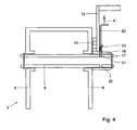
- the leg rest 1 shown in Figs. 1 - 4 comprises a substantially block-shaped supporting element 2 and a frame 3 with which the supporting element 2 can be connected to the fixed world W, this in a manner such that a side facing upwards of the supporting element 2 extends substantially horizontally and can thus serve as bearing face 4 for a leg P to be treated as shown in Fig. 1 .
- the supporting element 2 can for instance be designed as a block of wood, the side of which that serves as bearing face 4 preferably having a slight concave shape so that the leg P can be supported comfortably and the leg P can be better prevented from sliding from the bearing face.
- the fixed world W can for instance be a box stall or, as is the case in the exemplary embodiment shown in Fig. 1 , a cage-shaped construction in which the animal, during treatment, can be temporarily accommodated in order to limit its freedom of movement. If desired, such a construction can be designed to be wheeled.
- the term "fixed world" W is therefore to be interpreted broadly.
- the leg rest 1 further comprises a winch 5 for winding and unwinding an elongated element such as a band or cord 6.
- this cord 6 is fastened by one free end around the leg P to be treated, whereupon the leg P is hoisted with the winch onto the supporting element 2.
- the free cord end can be provided with suitable fastening means such as a loop, belt or hook (not shown) so that fastening around the leg P is simplified and/or the comfort for the animal is enhanced.
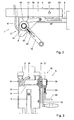
- the winch 5 comprises a spool 8 (see Fig. 3 ) which is suspended for rotation in the frame 3 between two side pieces 9.
- the above-mentioned cord 6 is fastened by a first end to this spool 8 and run by the free end through the supporting element 2, via an opening 1 provided thereto, all this being arranged such that, due to rotation of the spool 8, this cord 6 is wound in a winding direction (counter-clockwise in Fig. 2 ), and is unwound in an unwinding direction.
- a drive element 12 is provided which, in the example shown, is designed as a manually operable crank which is detachably coupled to an end of the spool 8 in a manner to be described further.
- the spool 8 further comprises blocking means 10 which, in a blocking position, allow rotation of the spool 8 in the winding direction but block in the unwinding direction.
- the blocking means 10 comprise a ratchet mechanism, provided with a toothed wheel 14, which, in a manner to be described further, is fastened to the spool 8 and can, thus, rotate along with the spool 8, a pawl 15, connected for rotation to the frame 3 and engaging, by a free end, the toothing of the wheel 14, and a stroke limiting device 13 in the form of a pin 13, arranged in the path of rotation of the pawl 15 and, thus, limiting the angle of rotation of the pawl 15 so that it cannot be rotated beyond its range of operation by too abrupt an acceleration of the wheel 14.
- the drive element (crank) 12 and the blocking means (toothed wheel) 14 are fastened to the spool 8 so they can be uncoupled via releasing means, in particular a coupling ring 18, which has been slid for rotation around a free end 17 of the spool 8 and can be coupled to this spool end 17 in a manner secured against rotation with the aid of a coupling pin 20, while the coupling pin 20 is run through opposing holes 21, 22, in the coupling ring 18 and the spool end 17, respectively.
- the coupling pin 20 is slideably connected to the crank 12 and is preferably biased in the above-mentioned coupled position, via biasing means 23, for instance a spiral spring as shown in Figs. 3 and 4 .
- This coupled position can be eliminated by manually pulling the coupling pin 20 back against the biasing force to an uncoupled position in which the pin 20 has been pulled from the holes 21, 22 in the direction of arrow A, in Fig. 4 .
- a locking option may be provided (not shown) for securing the coupling pin 20 in the uncoupled position so that a user can keep his both hands free for guiding the leg P.
- the connection secured against rotation between the spool 8 and coupling ring 18 will be eliminated.
- the spool 8 will be able to rotate freely relative to the coupling ring 18 and the drive element 12 and ratchet mechanism 10 connected thereto, while the blocking action of this ratchet mechanism 10 in unwinding direction will be eliminated.
- the leg rest 1 can further comprise various fastening provisions, such as an opening 24 and/or a cleat (as shown in Fig. 2 ) for fastening further cords, tensioning means or the like with which the leg P can be fixed on the supporting element 2 in a position for treatment.
- various fastening provisions such as an opening 24 and/or a cleat (as shown in Fig. 2 ) for fastening further cords, tensioning means or the like with which the leg P can be fixed on the supporting element 2 in a position for treatment.
- leg rest 1 can be used as follows. An animal to be treated is positioned adjacent the leg rest 1, whereupon the cord 6 is unwound to such an extent that it can be fastened around the leg P of the animal. To unwind the cord 6, the blocking means (the ratchet mechanism 10) are to be eliminated with the aid of the releasing means (coupling ring 10, coupling pin 20). To that end, the coupling pin 20 is pulled by hand in the direction of the arrow A, against the biasing force. As a result, also, the drive element (crank 12) is uncoupled, which is fixedly connected to the coupling ring 18. Hence, this crank 12 will not rotate along with the unwinding the cord 6 and the associated rotation of the spool 8.
- the coupling pin 20 is let go of or unlocked, so that it is brought by the biasing means 23 in the coupled position in which the coupling ring 18, the ratchet mechanism 10 and the crank 12 are connected to the spool 8 in a manner secured against rotation.
- the ratchet mechanism 10 prevents the cord 6 from being unwound due to any resisting forces of the animal.
- the cord 6 can be wound up until the leg P is located on the bearing face 4. Then, the leg P can be fixed in a desired position with further cords, tensioning means or the like that can be secured in the fastening means 24, 25. Thereupon, the leg P can be inspected and/or treated.
- the blocking action of the ratchet mechanism 10 is eliminated in a manner described hereinabove, that is to say by pulling the coupling pin 20 by hand from the coupled position against the biasing force.
- the crank 12 will be uncoupled so that it will not rotate along with the spool 8. Instead thereof, the crank 12 is held in a position of rest by the pawl 15. In this manner, dangerous situations can be avoided as sudden jerks to the cord by the animal, and associated sudden rotation of the spool 8 cannot be transmitted to the crank 12.
- the drive element and the blocking means can be coupled to the spool of the winch via separate coupling and/or releasing means, while the releasing means for uncoupling (eliminating) the blocking means can be operated or become accessible only after the drive element has been uncoupled.
- the drive element is prevented from not being connected to the spool when this spool can unwind.
- the drive element can be fastened to the spool of the winch by means of a second ratchet mechanism, whereby, in a winding direction, the drive element is connected to the spool in a manner secured against rotation and can rotate freely in opposite direction relative to the spool.
Landscapes
- Engineering & Computer Science (AREA)
- Mechanical Engineering (AREA)
- Catching Or Destruction (AREA)
- Housing For Livestock And Birds (AREA)
- Processing Of Meat And Fish (AREA)
Claims (10)
- Vorrichtung (1) zum Abstützen eines Beins (P) eines Tieres, umfassend ein Abstützelement (2) und eine Winde (5) zum Aufziehen des jeweiligen Beins (P) auf das Abstützelement (2),
wobei die Winde umfasst
eine drehbare Spule (8), die mit einem Antriebselement (12) zum Aufwinden und Abwinden eines verlängerten Elements (6) versehen ist,
eine Blockiervorrichtung zum Blockieren des Abwickelns des verlängerten Elements (6),
eine Lösevorrichtung zum Deaktivieren der Blockiervorrichtung (10) zumindest beim Loslösen des Abwickelns des verlängerten Elements (6) und
wobei eine Ruhigstellvorrichtung vorgesehen ist, um zumindest in einer Abwickelrichtung das Antriebselement (10), solange die Blockiervorrichtung (10) deaktiviert ist, ruhig zu stellen,
dadurch gekennzeichnet, dass die Ruhigstellvorrichtung einen Freilaufmechanismus oder einen Sperrklinkenmechanismus aufweist, der das Antriebselement (12) mit der Spule (8) auf eine Weise verbindet, die gegen Drehung in der Aufwickelrichtung gesichert ist und eine Drehung in der Abwickelrichtung gestattet,
wobei die Blockiervorrichtung einen Freilaufmechanismus oder einen Sperrklinkenmechanismus aufweist, der die Drehung der Spule in der Aufwickelrichtung gestattet, aber sie in der Abwickelrichtung blockiert, und
wobei die Blockiervorrichtung (10) und die Ruhigstellvorrichtung über ein gemeinsames Verbindungsteil (18) mit der Spule (8) verbunden sind,
wobei das Verbindungsteil (18) mit der Spule (8) mittels der Lösevorrichtung wahlweise auf eine Weise, die gegen eine Drehung gesichert ist, oder auf eine frei rotierbare Weise verbunden werden kann,
wobei die Lösevorrichtung so gestaltet ist, dass durch Deaktivierung der Blockiervorrichtung (10) die Ruhigstellvorrichtung aktiviert wird, sodass das Antriebselement (12) ruhig gestellt wird. - Vorrichtung nach Anspruch 1, bei der die Ruhigstellvorrichtung aktiviert und deaktiviert werden kann.
- Vorrichtung nach einem der vorhergehenden Ansprüche, bei der der Sperrklinkenmechanismus mit einem Rad (14) mit einem gezahnten Umfang und einer Sperrklinke (15), die angeordnet ist, um sich in und aus dem Pfad der Bewegung des gezahnten Umfangs zu bewegen, versehen ist.
- Vorrichtung nach Anspruch 3, bei der, mit der Hilfe der Lösevorrichtung, das Rad (14) wahlweise mit der Spule (8) auf eine Weise, die gegen Drehung gesichert ist, oder auf eine frei drehbare Weise verbunden werden kann.
- Vorrichtung nach einem der vorhergehenden Ansprüche, bei der das Verbindungsteil einen Verbindungsring (18), der um ein Ende der Spule (8) vorgesehen ist, umfasst.
- Vorrichtung nach einem der vorhergehenden Ansprüche, bei der die Lösevorrichtung einen Verbindungspin (20) umfasst, der zwischen einer verbundenen Position, in der sich der Pin in das Kupplungsteil (18) und die Spule (8) erstreckt, und einer Löseposition, in der sich der Verbindungsteil (18) relativ zu der Spule (8) frei drehen kann, versetzt werden kann.
- Vorrichtung nach einem der vorhergehenden Ansprüche, bei der die Lösevorrichtung (20) in einer verbundenen Position, in der die Blockiervorrichtung (10) aktiviert ist, vorgespannt ist.
- Vorrichtung nach einem der vorhergehenden Ansprüche, bei der eine Verriegelungsvorrichtung zum Befestigen der Lösevorrichtung in einer Löseposition, in der die Blockiervorrichtung deaktiviert ist, vorgesehen ist.
- Vorrichtung nach einem der vorhergehenden Ansprüche, bei der das verlängerte Element (6) mit einer Befestigungsvorrichtung, um ein zu stützendes Bein (P) zu befestigen, versehen ist.
- Vorrichtung zur Behandlung eines vierbeinigen Tieres, umfassend einen käfigförmigen Aufbau, der aufgebaut ist, um die Bewegungsfreiheit eines Tieres, das in diesem Aufbau untergebracht ist, einzuschränken, wobei die Vorrichtung zumindest eine Stützvorrichtung (1) gemäß einem der vorhergehenden Ansprüche aufweist.
Applications Claiming Priority (1)
| Application Number | Priority Date | Filing Date | Title |
|---|---|---|---|
| NL1028813A NL1028813C2 (nl) | 2005-04-19 | 2005-04-19 | Inrichting voor het ondersteunen van een poot van een dier. |
Publications (2)
| Publication Number | Publication Date |
|---|---|
| EP1714552A1 EP1714552A1 (de) | 2006-10-25 |
| EP1714552B1 true EP1714552B1 (de) | 2010-03-03 |
Family
ID=35262118
Family Applications (1)
| Application Number | Title | Priority Date | Filing Date |
|---|---|---|---|
| EP06075910A Not-in-force EP1714552B1 (de) | 2005-04-19 | 2006-04-18 | Vorrichtung zur Stützung eines Tierbeines |
Country Status (4)
| Country | Link |
|---|---|
| EP (1) | EP1714552B1 (de) |
| AT (1) | ATE459249T1 (de) |
| DE (1) | DE602006012570D1 (de) |
| NL (1) | NL1028813C2 (de) |
Cited By (1)
| Publication number | Priority date | Publication date | Assignee | Title |
|---|---|---|---|---|
| WO2014051704A1 (en) * | 2012-09-27 | 2014-04-03 | Champagne Wesley Jon | Artificial horse leg stand |
Families Citing this family (1)
| Publication number | Priority date | Publication date | Assignee | Title |
|---|---|---|---|---|
| CN103548711B (zh) * | 2013-10-24 | 2014-11-19 | 广西大学 | 机电一体调节旋转试验机 |
Citations (1)
| Publication number | Priority date | Publication date | Assignee | Title |
|---|---|---|---|---|
| DE3114939A1 (de) * | 1981-04-13 | 1982-10-28 | Hans Clauss Maschinenbau, 7340 Geislingen | Vorrichtung zum hochziehen und festsetzen von tierfuessen |
Family Cites Families (5)
| Publication number | Priority date | Publication date | Assignee | Title |
|---|---|---|---|---|
| DE371716C (de) * | 1923-03-17 | Georg Schwarzmann | Beschlagstand fuer Pferde und Rinder | |
| GB1214031A (en) * | 1968-02-01 | 1970-11-25 | C J R Fyson & Son Ltd | Improvements in or relating to safety catch means for rotatable handles |
| DE2919281C2 (de) * | 1979-05-12 | 1981-12-03 | Alfred 8831 Biburg Pfaller | Zwangsstand für Großvieh |
| FR2595204B1 (fr) * | 1986-03-07 | 1988-12-09 | Collomb Andre | Appareil portable pour la contention des bovins |
| NL1020894C2 (nl) * | 2002-06-18 | 2003-04-02 | Wopa B V | Inrichting voor het behandelen van een achterpoot van een vierpotig dier. |
-
2005
- 2005-04-19 NL NL1028813A patent/NL1028813C2/nl not_active IP Right Cessation
-
2006
- 2006-04-18 DE DE602006012570T patent/DE602006012570D1/de active Active
- 2006-04-18 EP EP06075910A patent/EP1714552B1/de not_active Not-in-force
- 2006-04-18 AT AT06075910T patent/ATE459249T1/de not_active IP Right Cessation
Patent Citations (1)
| Publication number | Priority date | Publication date | Assignee | Title |
|---|---|---|---|---|
| DE3114939A1 (de) * | 1981-04-13 | 1982-10-28 | Hans Clauss Maschinenbau, 7340 Geislingen | Vorrichtung zum hochziehen und festsetzen von tierfuessen |
Non-Patent Citations (1)
| Title |
|---|
| BEITZ W.; GROTE K.-H.: "TASCHENBUCH FÜR DEN MASCHINENBAU", 1997, SPRINGER-VERLAG, BERLIN, D * |
Cited By (1)
| Publication number | Priority date | Publication date | Assignee | Title |
|---|---|---|---|---|
| WO2014051704A1 (en) * | 2012-09-27 | 2014-04-03 | Champagne Wesley Jon | Artificial horse leg stand |
Also Published As
| Publication number | Publication date |
|---|---|
| EP1714552A1 (de) | 2006-10-25 |
| NL1028813C2 (nl) | 2006-10-20 |
| DE602006012570D1 (de) | 2010-04-15 |
| ATE459249T1 (de) | 2010-03-15 |
Similar Documents
| Publication | Publication Date | Title |
|---|---|---|
| US5156240A (en) | Rope grab | |
| US4130176A (en) | Combination safety belt and safety line | |
| US8851232B2 (en) | Rope climbing apparatus | |
| US8226138B2 (en) | Apparatus for securing rescue operations by helihoisting | |
| JP6162122B2 (ja) | ストラップ用ラチェット装置及びその使用 | |
| US6017173A (en) | Web retractor with release lever and tightening handle | |
| JP2005125077A (ja) | 係止ローラーを有する墜落防止装置 | |
| US4356816A (en) | Traction device | |
| AU2006222451B2 (en) | Abseiling device having a winch function | |
| AU2019275480B2 (en) | Fall control ladder | |
| US20100012425A1 (en) | Stop Element For A Securing Device | |
| US10737916B2 (en) | Manual marine winch with safety loading handle and integrated locking dog release | |
| JPH09511410A (ja) | 落下防止安全装置 | |
| WO2017039545A1 (en) | Container lashing process and system | |
| CN104870360B (zh) | 吊钩及用于吊钩的安全闩锁 | |
| US9096298B1 (en) | Rescue pole | |
| KR101901598B1 (ko) | 다기능 자동 양승기. | |
| EP1714552B1 (de) | Vorrichtung zur Stützung eines Tierbeines | |
| US2961217A (en) | Winch or hoist brake | |
| US4311217A (en) | Descent control unit | |
| US20200369497A1 (en) | Rotary Winch | |
| US4787474A (en) | Rope controller | |
| WO2015145363A1 (en) | Kite line reeling device | |
| KR20240020838A (ko) | 드래그 다운먼트 | |
| JPH0745234Y2 (ja) | 墜落防止用ベルトの巻取器 |
Legal Events
| Date | Code | Title | Description |
|---|---|---|---|
| PUAI | Public reference made under article 153(3) epc to a published international application that has entered the european phase |
Free format text: ORIGINAL CODE: 0009012 |
|
| AK | Designated contracting states |
Kind code of ref document: A1 Designated state(s): AT BE BG CH CY CZ DE DK EE ES FI FR GB GR HU IE IS IT LI LT LU LV MC NL PL PT RO SE SI SK TR |
|
| AX | Request for extension of the european patent |
Extension state: AL BA HR MK YU |
|
| 17P | Request for examination filed |
Effective date: 20070405 |
|
| 17Q | First examination report despatched |
Effective date: 20070511 |
|
| AKX | Designation fees paid |
Designated state(s): AT BE BG CH CY CZ DE DK EE ES FI FR GB GR HU IE IS IT LI LT LU LV MC NL PL PT RO SE SI SK TR |
|
| GRAP | Despatch of communication of intention to grant a patent |
Free format text: ORIGINAL CODE: EPIDOSNIGR1 |
|
| GRAS | Grant fee paid |
Free format text: ORIGINAL CODE: EPIDOSNIGR3 |
|
| GRAA | (expected) grant |
Free format text: ORIGINAL CODE: 0009210 |
|
| AK | Designated contracting states |
Kind code of ref document: B1 Designated state(s): AT BE BG CH CY CZ DE DK EE ES FI FR GB GR HU IE IS IT LI LT LU LV MC NL PL PT RO SE SI SK TR |
|
| REG | Reference to a national code |
Ref country code: GB Ref legal event code: FG4D |
|
| REG | Reference to a national code |
Ref country code: CH Ref legal event code: EP |
|
| REG | Reference to a national code |
Ref country code: IE Ref legal event code: FG4D |
|
| REF | Corresponds to: |
Ref document number: 602006012570 Country of ref document: DE Date of ref document: 20100415 Kind code of ref document: P |
|
| REG | Reference to a national code |
Ref country code: NL Ref legal event code: T3 |
|
| PG25 | Lapsed in a contracting state [announced via postgrant information from national office to epo] |
Ref country code: LT Free format text: LAPSE BECAUSE OF FAILURE TO SUBMIT A TRANSLATION OF THE DESCRIPTION OR TO PAY THE FEE WITHIN THE PRESCRIBED TIME-LIMIT Effective date: 20100303 |
|
| LTIE | Lt: invalidation of european patent or patent extension |
Effective date: 20100303 |
|
| PG25 | Lapsed in a contracting state [announced via postgrant information from national office to epo] |
Ref country code: LV Free format text: LAPSE BECAUSE OF FAILURE TO SUBMIT A TRANSLATION OF THE DESCRIPTION OR TO PAY THE FEE WITHIN THE PRESCRIBED TIME-LIMIT Effective date: 20100303 Ref country code: FI Free format text: LAPSE BECAUSE OF FAILURE TO SUBMIT A TRANSLATION OF THE DESCRIPTION OR TO PAY THE FEE WITHIN THE PRESCRIBED TIME-LIMIT Effective date: 20100303 Ref country code: AT Free format text: LAPSE BECAUSE OF FAILURE TO SUBMIT A TRANSLATION OF THE DESCRIPTION OR TO PAY THE FEE WITHIN THE PRESCRIBED TIME-LIMIT Effective date: 20100303 Ref country code: SI Free format text: LAPSE BECAUSE OF FAILURE TO SUBMIT A TRANSLATION OF THE DESCRIPTION OR TO PAY THE FEE WITHIN THE PRESCRIBED TIME-LIMIT Effective date: 20100303 Ref country code: PL Free format text: LAPSE BECAUSE OF FAILURE TO SUBMIT A TRANSLATION OF THE DESCRIPTION OR TO PAY THE FEE WITHIN THE PRESCRIBED TIME-LIMIT Effective date: 20100303 |
|
| PG25 | Lapsed in a contracting state [announced via postgrant information from national office to epo] |
Ref country code: GR Free format text: LAPSE BECAUSE OF FAILURE TO SUBMIT A TRANSLATION OF THE DESCRIPTION OR TO PAY THE FEE WITHIN THE PRESCRIBED TIME-LIMIT Effective date: 20100604 Ref country code: CY Free format text: LAPSE BECAUSE OF FAILURE TO SUBMIT A TRANSLATION OF THE DESCRIPTION OR TO PAY THE FEE WITHIN THE PRESCRIBED TIME-LIMIT Effective date: 20100303 Ref country code: SE Free format text: LAPSE BECAUSE OF FAILURE TO SUBMIT A TRANSLATION OF THE DESCRIPTION OR TO PAY THE FEE WITHIN THE PRESCRIBED TIME-LIMIT Effective date: 20100303 Ref country code: EE Free format text: LAPSE BECAUSE OF FAILURE TO SUBMIT A TRANSLATION OF THE DESCRIPTION OR TO PAY THE FEE WITHIN THE PRESCRIBED TIME-LIMIT Effective date: 20100303 Ref country code: ES Free format text: LAPSE BECAUSE OF FAILURE TO SUBMIT A TRANSLATION OF THE DESCRIPTION OR TO PAY THE FEE WITHIN THE PRESCRIBED TIME-LIMIT Effective date: 20100614 Ref country code: RO Free format text: LAPSE BECAUSE OF FAILURE TO SUBMIT A TRANSLATION OF THE DESCRIPTION OR TO PAY THE FEE WITHIN THE PRESCRIBED TIME-LIMIT Effective date: 20100303 |
|
| PG25 | Lapsed in a contracting state [announced via postgrant information from national office to epo] |
Ref country code: CZ Free format text: LAPSE BECAUSE OF FAILURE TO SUBMIT A TRANSLATION OF THE DESCRIPTION OR TO PAY THE FEE WITHIN THE PRESCRIBED TIME-LIMIT Effective date: 20100303 Ref country code: BG Free format text: LAPSE BECAUSE OF FAILURE TO SUBMIT A TRANSLATION OF THE DESCRIPTION OR TO PAY THE FEE WITHIN THE PRESCRIBED TIME-LIMIT Effective date: 20100603 Ref country code: MC Free format text: LAPSE BECAUSE OF NON-PAYMENT OF DUE FEES Effective date: 20100430 Ref country code: SK Free format text: LAPSE BECAUSE OF FAILURE TO SUBMIT A TRANSLATION OF THE DESCRIPTION OR TO PAY THE FEE WITHIN THE PRESCRIBED TIME-LIMIT Effective date: 20100303 Ref country code: IS Free format text: LAPSE BECAUSE OF FAILURE TO SUBMIT A TRANSLATION OF THE DESCRIPTION OR TO PAY THE FEE WITHIN THE PRESCRIBED TIME-LIMIT Effective date: 20100703 |
|
| REG | Reference to a national code |
Ref country code: CH Ref legal event code: PL |
|
| PLBE | No opposition filed within time limit |
Free format text: ORIGINAL CODE: 0009261 |
|
| STAA | Information on the status of an ep patent application or granted ep patent |
Free format text: STATUS: NO OPPOSITION FILED WITHIN TIME LIMIT |
|
| PG25 | Lapsed in a contracting state [announced via postgrant information from national office to epo] |
Ref country code: PT Free format text: LAPSE BECAUSE OF FAILURE TO SUBMIT A TRANSLATION OF THE DESCRIPTION OR TO PAY THE FEE WITHIN THE PRESCRIBED TIME-LIMIT Effective date: 20100705 Ref country code: IE Free format text: LAPSE BECAUSE OF NON-PAYMENT OF DUE FEES Effective date: 20100418 Ref country code: DK Free format text: LAPSE BECAUSE OF FAILURE TO SUBMIT A TRANSLATION OF THE DESCRIPTION OR TO PAY THE FEE WITHIN THE PRESCRIBED TIME-LIMIT Effective date: 20100303 |
|
| 26N | No opposition filed |
Effective date: 20101206 |
|
| PG25 | Lapsed in a contracting state [announced via postgrant information from national office to epo] |
Ref country code: LI Free format text: LAPSE BECAUSE OF NON-PAYMENT OF DUE FEES Effective date: 20100430 Ref country code: CH Free format text: LAPSE BECAUSE OF NON-PAYMENT OF DUE FEES Effective date: 20100430 |
|
| PG25 | Lapsed in a contracting state [announced via postgrant information from national office to epo] |
Ref country code: IT Free format text: LAPSE BECAUSE OF FAILURE TO SUBMIT A TRANSLATION OF THE DESCRIPTION OR TO PAY THE FEE WITHIN THE PRESCRIBED TIME-LIMIT Effective date: 20100303 |
|
| PG25 | Lapsed in a contracting state [announced via postgrant information from national office to epo] |
Ref country code: HU Free format text: LAPSE BECAUSE OF FAILURE TO SUBMIT A TRANSLATION OF THE DESCRIPTION OR TO PAY THE FEE WITHIN THE PRESCRIBED TIME-LIMIT Effective date: 20100904 |
|
| PG25 | Lapsed in a contracting state [announced via postgrant information from national office to epo] |
Ref country code: TR Free format text: LAPSE BECAUSE OF FAILURE TO SUBMIT A TRANSLATION OF THE DESCRIPTION OR TO PAY THE FEE WITHIN THE PRESCRIBED TIME-LIMIT Effective date: 20100303 |
|
| REG | Reference to a national code |
Ref country code: FR Ref legal event code: PLFP Year of fee payment: 11 |
|
| REG | Reference to a national code |
Ref country code: FR Ref legal event code: PLFP Year of fee payment: 12 |
|
| REG | Reference to a national code |
Ref country code: FR Ref legal event code: PLFP Year of fee payment: 13 |
|
| REG | Reference to a national code |
Ref country code: DE Ref legal event code: R082 Ref document number: 602006012570 Country of ref document: DE Representative=s name: VEREENIGDE OCTROOIBUREAUX V.O., DE |
|
| PGFP | Annual fee paid to national office [announced via postgrant information from national office to epo] |
Ref country code: NL Payment date: 20210323 Year of fee payment: 16 |
|
| PGFP | Annual fee paid to national office [announced via postgrant information from national office to epo] |
Ref country code: LU Payment date: 20210420 Year of fee payment: 16 |
|
| PGFP | Annual fee paid to national office [announced via postgrant information from national office to epo] |
Ref country code: DE Payment date: 20210420 Year of fee payment: 16 Ref country code: FR Payment date: 20210423 Year of fee payment: 16 |
|
| PGFP | Annual fee paid to national office [announced via postgrant information from national office to epo] |
Ref country code: BE Payment date: 20210420 Year of fee payment: 16 Ref country code: GB Payment date: 20210421 Year of fee payment: 16 |
|
| REG | Reference to a national code |
Ref country code: DE Ref legal event code: R119 Ref document number: 602006012570 Country of ref document: DE |
|
| REG | Reference to a national code |
Ref country code: NL Ref legal event code: MM Effective date: 20220501 |
|
| GBPC | Gb: european patent ceased through non-payment of renewal fee |
Effective date: 20220418 |
|
| REG | Reference to a national code |
Ref country code: BE Ref legal event code: MM Effective date: 20220430 |
|
| PG25 | Lapsed in a contracting state [announced via postgrant information from national office to epo] |
Ref country code: NL Free format text: LAPSE BECAUSE OF NON-PAYMENT OF DUE FEES Effective date: 20220501 Ref country code: LU Free format text: LAPSE BECAUSE OF NON-PAYMENT OF DUE FEES Effective date: 20220418 Ref country code: GB Free format text: LAPSE BECAUSE OF NON-PAYMENT OF DUE FEES Effective date: 20220418 Ref country code: FR Free format text: LAPSE BECAUSE OF NON-PAYMENT OF DUE FEES Effective date: 20220430 Ref country code: DE Free format text: LAPSE BECAUSE OF NON-PAYMENT OF DUE FEES Effective date: 20221103 |
|
| PG25 | Lapsed in a contracting state [announced via postgrant information from national office to epo] |
Ref country code: BE Free format text: LAPSE BECAUSE OF NON-PAYMENT OF DUE FEES Effective date: 20220430 |