EP1712936A2 - Lichtleitfasersystem zum Bereitstellen von Hochleistungsimpulsen geringer Dauer - Google Patents
Lichtleitfasersystem zum Bereitstellen von Hochleistungsimpulsen geringer Dauer Download PDFInfo
- Publication number
- EP1712936A2 EP1712936A2 EP06003432A EP06003432A EP1712936A2 EP 1712936 A2 EP1712936 A2 EP 1712936A2 EP 06003432 A EP06003432 A EP 06003432A EP 06003432 A EP06003432 A EP 06003432A EP 1712936 A2 EP1712936 A2 EP 1712936A2
- Authority
- EP
- European Patent Office
- Prior art keywords
- fiber
- optical
- pulses
- dispersion
- optical fiber
- Prior art date
- Legal status (The legal status is an assumption and is not a legal conclusion. Google has not performed a legal analysis and makes no representation as to the accuracy of the status listed.)
- Granted
Links
- 239000013307 optical fiber Substances 0.000 title claims abstract description 35
- 239000006185 dispersion Substances 0.000 claims abstract description 59
- 230000003287 optical effect Effects 0.000 claims abstract description 37
- 238000000034 method Methods 0.000 claims description 8
- 101710121003 Oxygen-evolving enhancer protein 3, chloroplastic Proteins 0.000 claims description 5
- 230000001902 propagating effect Effects 0.000 claims description 4
- RTAQQCXQSZGOHL-UHFFFAOYSA-N Titanium Chemical group [Ti] RTAQQCXQSZGOHL-UHFFFAOYSA-N 0.000 claims 1
- 229910052719 titanium Inorganic materials 0.000 claims 1
- 239000010936 titanium Substances 0.000 claims 1
- 239000000835 fiber Substances 0.000 abstract description 114
- 230000006735 deficit Effects 0.000 abstract description 3
- 238000013461 design Methods 0.000 description 12
- VYPSYNLAJGMNEJ-UHFFFAOYSA-N Silicium dioxide Chemical compound O=[Si]=O VYPSYNLAJGMNEJ-UHFFFAOYSA-N 0.000 description 5
- 230000008878 coupling Effects 0.000 description 5
- 238000010168 coupling process Methods 0.000 description 5
- 238000005859 coupling reaction Methods 0.000 description 5
- 238000007493 shaping process Methods 0.000 description 5
- 206010028980 Neoplasm Diseases 0.000 description 4
- 230000000694 effects Effects 0.000 description 4
- 230000005540 biological transmission Effects 0.000 description 3
- 238000006243 chemical reaction Methods 0.000 description 3
- 239000000463 material Substances 0.000 description 3
- 238000004651 near-field scanning optical microscopy Methods 0.000 description 3
- 230000008569 process Effects 0.000 description 3
- 201000011510 cancer Diseases 0.000 description 2
- 238000005253 cladding Methods 0.000 description 2
- 238000004891 communication Methods 0.000 description 2
- 238000001514 detection method Methods 0.000 description 2
- 238000004519 manufacturing process Methods 0.000 description 2
- 238000005259 measurement Methods 0.000 description 2
- 238000000386 microscopy Methods 0.000 description 2
- 230000009022 nonlinear effect Effects 0.000 description 2
- 230000000644 propagated effect Effects 0.000 description 2
- 238000011160 research Methods 0.000 description 2
- 229910052594 sapphire Inorganic materials 0.000 description 2
- 239000010980 sapphire Substances 0.000 description 2
- 239000000377 silicon dioxide Substances 0.000 description 2
- 239000010409 thin film Substances 0.000 description 2
- 229910001218 Gallium arsenide Inorganic materials 0.000 description 1
- 238000013459 approach Methods 0.000 description 1
- 239000000090 biomarker Substances 0.000 description 1
- 239000012141 concentrate Substances 0.000 description 1
- 230000003247 decreasing effect Effects 0.000 description 1
- 230000002939 deleterious effect Effects 0.000 description 1
- 238000009792 diffusion process Methods 0.000 description 1
- 229940079593 drug Drugs 0.000 description 1
- 239000003814 drug Substances 0.000 description 1
- 239000000975 dye Substances 0.000 description 1
- 238000005516 engineering process Methods 0.000 description 1
- 230000005284 excitation Effects 0.000 description 1
- 238000002474 experimental method Methods 0.000 description 1
- 239000002657 fibrous material Substances 0.000 description 1
- 238000000799 fluorescence microscopy Methods 0.000 description 1
- 230000004927 fusion Effects 0.000 description 1
- 229910052732 germanium Inorganic materials 0.000 description 1
- GNPVGFCGXDBREM-UHFFFAOYSA-N germanium atom Chemical compound [Ge] GNPVGFCGXDBREM-UHFFFAOYSA-N 0.000 description 1
- 239000003365 glass fiber Substances 0.000 description 1
- 238000001727 in vivo Methods 0.000 description 1
- 238000000691 measurement method Methods 0.000 description 1
- 230000001404 mediated effect Effects 0.000 description 1
- 238000012986 modification Methods 0.000 description 1
- 230000004048 modification Effects 0.000 description 1
- 230000008520 organization Effects 0.000 description 1
- 230000010363 phase shift Effects 0.000 description 1
- 239000004038 photonic crystal Substances 0.000 description 1
- 230000010287 polarization Effects 0.000 description 1
- 230000009467 reduction Effects 0.000 description 1
- 230000004044 response Effects 0.000 description 1
- 239000000523 sample Substances 0.000 description 1
- 230000003595 spectral effect Effects 0.000 description 1
- 230000000451 tissue damage Effects 0.000 description 1
- 231100000827 tissue damage Toxicity 0.000 description 1
- 230000001131 transforming effect Effects 0.000 description 1
Images


Classifications
-
- G—PHYSICS
- G02—OPTICS
- G02B—OPTICAL ELEMENTS, SYSTEMS OR APPARATUS
- G02B6/00—Light guides; Structural details of arrangements comprising light guides and other optical elements, e.g. couplings
- G02B6/02—Optical fibres with cladding with or without a coating
- G02B6/02004—Optical fibres with cladding with or without a coating characterised by the core effective area or mode field radius
- G02B6/02009—Large effective area or mode field radius, e.g. to reduce nonlinear effects in single mode fibres
- G02B6/02023—Based on higher order modes, i.e. propagating modes other than the LP01 or HE11 fundamental mode
-
- G—PHYSICS
- G02—OPTICS
- G02B—OPTICAL ELEMENTS, SYSTEMS OR APPARATUS
- G02B6/00—Light guides; Structural details of arrangements comprising light guides and other optical elements, e.g. couplings
- G02B6/02—Optical fibres with cladding with or without a coating
- G02B6/02214—Optical fibres with cladding with or without a coating tailored to obtain the desired dispersion, e.g. dispersion shifted, dispersion flattened
-
- G—PHYSICS
- G02—OPTICS
- G02B—OPTICAL ELEMENTS, SYSTEMS OR APPARATUS
- G02B6/00—Light guides; Structural details of arrangements comprising light guides and other optical elements, e.g. couplings
- G02B6/02—Optical fibres with cladding with or without a coating
- G02B6/036—Optical fibres with cladding with or without a coating core or cladding comprising multiple layers
- G02B6/03616—Optical fibres characterised both by the number of different refractive index layers around the central core segment, i.e. around the innermost high index core layer, and their relative refractive index difference
- G02B6/03638—Optical fibres characterised both by the number of different refractive index layers around the central core segment, i.e. around the innermost high index core layer, and their relative refractive index difference having 3 layers only
- G02B6/03644—Optical fibres characterised both by the number of different refractive index layers around the central core segment, i.e. around the innermost high index core layer, and their relative refractive index difference having 3 layers only arranged - + -
-
- H—ELECTRICITY
- H04—ELECTRIC COMMUNICATION TECHNIQUE
- H04B—TRANSMISSION
- H04B10/00—Transmission systems employing electromagnetic waves other than radio-waves, e.g. infrared, visible or ultraviolet light, or employing corpuscular radiation, e.g. quantum communication
- H04B10/25—Arrangements specific to fibre transmission
-
- H—ELECTRICITY
- H04—ELECTRIC COMMUNICATION TECHNIQUE
- H04B—TRANSMISSION
- H04B10/00—Transmission systems employing electromagnetic waves other than radio-waves, e.g. infrared, visible or ultraviolet light, or employing corpuscular radiation, e.g. quantum communication
- H04B10/25—Arrangements specific to fibre transmission
- H04B10/2507—Arrangements specific to fibre transmission for the reduction or elimination of distortion or dispersion
-
- H—ELECTRICITY
- H04—ELECTRIC COMMUNICATION TECHNIQUE
- H04B—TRANSMISSION
- H04B10/00—Transmission systems employing electromagnetic waves other than radio-waves, e.g. infrared, visible or ultraviolet light, or employing corpuscular radiation, e.g. quantum communication
- H04B10/25—Arrangements specific to fibre transmission
- H04B10/2507—Arrangements specific to fibre transmission for the reduction or elimination of distortion or dispersion
- H04B10/2513—Arrangements specific to fibre transmission for the reduction or elimination of distortion or dispersion due to chromatic dispersion
- H04B10/2525—Arrangements specific to fibre transmission for the reduction or elimination of distortion or dispersion due to chromatic dispersion using dispersion-compensating fibres
Definitions
- This invention relates to optical fiber systems that produce very short, high power, optical pulses.
- Optical fiber lasers are available that produce optical pulses with high pulse energy, good beam quality and excellent optical characteristics.
- Several applications for these optical pulse lasers exist ranging from time-resolved near-field scanning optical microscopy (NSOM) pump-probe experiments for understanding ultrafast electronic processes in materials (see S. Smith, N.C.R. Holme, B. Orr, R. Kopelman and T.B.Norris, "Ultrafast measurement in GaAs thin films using NSOM,” Ultramicroscopy, vol. 71, pp. 213-223, 1998 ); for two-photon fluorescence of dyes (see A. Lago, A.T. Obeidat, A.E. Kaplan, J.B. Khurgin, P.L.
- the fs pulse acts as the pump beam that excites fluorescence mediated by a 2-photon process. Since multi-photo processes are by nature inefficient, high peak powers are needed. However, this cannot be achieved by increasing the average power of the source, because high average power will cause tissue damage. Hence, such applications typically require pulses of the duration of roughly 100 fs, with pulse energies as high as 1 nJ, while the average power is maintained at roughly 100 mW or lower.
- a commonly used laser source for such schemes is a mode-locked Ti:Sapphire laser that can output very high peak powers with repitition rates of ⁇ 80 MHz.
- the delivery fiber desirably propagates the high power, short pulses through a (typically) 1-2 meter-long fiber, and provides an output that is close in characteristics to the laser output.
- the dispersion of the fiber due to material as well as waveguide dispersion, leads to pulse broadening that transforms the 100-fs pulse at the input of the fiber into 10-20 ps long pulse at the fiber-output.
- SPM self-phase modulation
- the dispersion effect is linear, and thus may be compensated by a bulk linear chirp element between the Ti:Sapphire output and fiber input.
- the linear chirp element may be a bulk grating or prism pair used to stretch or compress pulses.
- Such elements are capable of providing arbitrary amounts of positive or negative dispersion. For this application, they may be adjusted to provide dispersion that is equal in magnitude, but opposite in sign to that of the specified length of the fiber endoscope/delivery medium.
- the nonlinear SPM effect is non-recoverable.
- a majority of fiber delivery schemes work with special fibers or complicated phase engineering of pulses to counteract the SPM effect.
- the delivery fiber should also be a single mode fiber with low loss.
- Propagation in multiple modes degrades the ability to tightly focus the output from the fiber.
- a tightly focused output enables concentrating the high peak power pulse on a small region, thus enabling efficient 2-photon fluorescence, as well as ensuring high resolution for microscopy applications.
- Propagation in multiple modes also spreads the pulses due to modal dispersion, which lowers the peak power and reduces the efficiency of nonlinear measurement techniques.
- connection losses include the concatenation of a collimating element at the fiber output. This element will focus the output to a tight spot.
- Candidates for the collimating element are fiber-GRIN lenses, or thin-film-based diffractive optic elements such as mode transformers, or other beam shaping elements.
- such miniature beam shaping elements can be epoxy-bonded to the tip of the fiber, but considering that very high peak powers will emanate from the fiber, it is desirable that a mode transforming element such a long-period grating or GRIN lens be used, since they are fiber-based, and can be easily fusion spliced to the output of the fiber, with low loss and high power handling capability.
- the baseline candidate for the delivery fiber is a standard fiber (doped core, and silica cladding) which is single-moded at the desired wavelength of operation.
- a typical desired operating wavelength is ⁇ 800 nm (for Ti:Sapphire lasers), and the effective area (A eff ) of a standard single mode fiber (SMF) at this wavelength is ⁇ 25 ⁇ m 2 .
- SMF standard single mode fiber
- This fiber satisfies all the above criteria, but at pulse energies > 0.1 nJ, SPM severely distorts the pulse.
- the pulse width rapidly expands past 250 fs (desired pulse widths are ⁇ 200 fs).
- a variation of the above solution is to use a large core, multimoded microstructure fiber. See D. Ouzounov, K. Moll, M. Foster, W. Zipfel, W.W. Webb and A.L. Gaeta, "Delivery of nanojoule femtosecond pulses through large-core microstructured fibers," Optics Letters, vol. 27, pp. 1513-1515, 2002 .
- Microstructured fibers are guided by a photonic crystal of air holes running through the glass fiber, and this mitigates mode coupling problems.
- coupling effectively only into the fundamental mode in microstructured fibers is a problem, and significant power is lost to higher order modes. This causes unwanted modal noise in the system.
- microstructured fibers have poor geometric control compared to standard doped fibers, and a potential drawback is geometric ovalities that would cause large polarization mode dispersion (PMD), a source of additional noise.
- PMD polarization mode dispersion
- photonic bandgap fibers where the signal propagates in a central air core. In this case, most of the signal energy resides in air, and hence undergoes negligible amounts of SPM-based pulse broadening.
- photonic bandgap fibers are difficult to manufacture in comparison to doped fibers, and hence are not a cost-effective solution. Geometric regularity problems are severely exacerbated, leading to the possibility of high PMD and associated problems. They also suffer from the inability to splice a mode-shaping element at the fiber output, because the splice causes the photonic bandgap effect to disappear, and will yield large losses.
- Another proposal is to use pulse shaping schemes to combat the nonlinear broadening in standard fibers.
- the pulse is temporally chirped, and spectrally narrowed before launching into the delivery fiber. While this produces short pulses, the power levels are low and not desirable for two-photon applications.
- the system is based on delivering the optical pulses in a higher order mode (HOM) of a few-moded fiber.
- HOM higher order mode
- the fiber is designed so that the dispersion for the HOM is very large. This results in a dispersion length L D for the delivery fiber that is exceptionally small, preferably less than the non-linear length L NL . Under these conditions the optical pulses experience minimum non-linear impairment, and short pulse/high peak power levels are reproduced at the output of the delivery fiber.
- ⁇ is the undistorted pulsewidth
- ⁇ 2 is the dispersion of the fiber waveguide
- c is the speed of light
- ⁇ is the central frequency of the pulse
- n 2 is the nonlinear response of the fiber material
- P peak is the peak power of the pulse in the fiber
- a eff is its effective area
- ⁇ is the central wavelength of the pulse.
- condition (2) is satisfied by holding L NL nominally constant and similar to that of SMF, but L D is significantly shortened by increasing the magnitude of (negative) dispersion provided by the HOM of the fiber.
- HOMs of specially designed few moded fibers are especially suited for this application, because HOMs can offer very high dispersion values, while maintaining a large A eff , and very low propagation and bend losses.
- the LP 11 mode of a fiber can have dispersions as high as - 700 ps/nm-km at the operation wavelength of 1550 nm.
- Optical fibers suitable for use in the invention have low ratios of L D /L NL , which enables high power pulse propagation for fs laser pulse delivery systems, as described earlier. In the preferred embodiments, this ratio is less than 1, and preferably less than 0.5.
- the specific optical fibers described here utilize the LP 02 of the fiber for pulse propagation, but similar designs can be achieved for any HOM. While such designs can be applied for any wavelength of operation, illustrative designs described below are optimized for fiber-delivery of Ti:Sapphire laser pulses, which nominally operate in the 800-nm wavelength range. That suggests that the wavelength range over which the devices of the invention preferably operate is 700-900. However, other wavelength regimes may also be found useful.
- the specific optical fiber designs used to illustrate the invention can be compared to SMF, which has a L D /L NL ratio of - 6.92, which yields undistorted pulses for pulse-energies up to 0.1 nJ (maximum undistorted pulse energy achievable with a fiber is roughly proportional to the L D /L NL ratio - value of L NL depends on pulse energy as well as undistorted width - this has been calculated for 1-nJ pulses of 100 fs width, in all cases illustrated here).
- the objective in some preferred embodiments, is to achieve L D /L NL ratios smaller than unity. Few mode fibers supporting these specially designed HOMs can be distinguished from standard multimode fibers in two respects.
- the fibers are intentionally designed to be highly dispersive for one particular, desired HOM, in contrast with multimode fibers, where most of the modes experience negligible waveguide dispersion, and the dispersion of all modes is similar to the material dispersion of silica glass.
- the fibers are designed such that the propagation constant of the desired HOM of propagation is sufficiently separated from other modes, so as to avoid intermodal coupling at bends.
- Fig. 1 shows an experimentally measured refractive index profile of a fiber fabricated to yield low L D /L NL ratios for 100-fs, 1-nJ pulses traveling in the LP 02 mode.
- Fig. 2 shows the measured dispersion for this fiber.
- Fig. 3 shows the A eff for the LP 02 mode.
- the LP 02 mode of this fiber has approximately 8 times larger negative dispersion compared to SMF (corresponding to reduction of dispersion length, L D by a factor of 8).
- the A eff is approximately 25 ⁇ m 2 at 840 nm, which is similar to that of SMF (SMF A eff ⁇ 20 ⁇ m 2 ).
- a delivery fiber with high bend losses or mode coupling would in most cases be unsuitable, for example, in endoscope applications where the fiber is expected to substantially bend during operation.
- a eff may be held to less than 50 microns 2 .
- Fig. 4 show the dispersion and A eff for the LP 02 mode at 800 nm for this fiber, respectively.
- dispersion values as high as -2300 ps/nm-km are easily achievable, with a similar A eff ( ⁇ 21 ⁇ m 2 ).
- the resultant L D /L NL ratio for this fiber is 0.29 (a factor of 24 smaller than SMF), yielding undistorted 100 fs pulses with energies as high as 2.4 nJ. This value comfortably surpasses the typical pulse energies required for several applications such as 2-photon fluorescence imaging for in-vivo cancer detection in live tissues.
- HOMs also provide a greater degree of design-freedom to achieve desired dispersion profiles, in addition to the large dispersion magnitudes.
- dispersion profiles in Figs. 2 and 5 have high, negative-dispersion-slopes, in addition to high magnitudes of dispersion.
- All fibers, including the large A eff microstructured fibers, and conventional SMF previously used for this application, have similar high dispersion slope values. This causes problems because most commonly available, bulk-optic-based pulse chirping elements used before the light enters the fiber, impart negligible dispersion slope to the pulse.
- Fig. 7 shows three different refractive index profiles, for fibers A, B, and C, each yielding high negative dispersion for the LP 02 mode. The dispersion curves for these three fibers are shown in Fig. 8.
- the profile for fiber A yields a negative dispersion slope, as do standard SMF or large area microstructured fibers, but profiles for fibers B and C yield zero and positive dispersion slope values, respectively. This enables efficient dispersion matching with any kind of bulk-optic pulse stretcher design.
- Fig. 9 shows an exemplary device schematic.
- the fiber device is preceded by an assembly comprising the short pulse laser followed by a bulk-optic pulse stretcher (the pulse stretcher is illustrated as a pair of bulk gratings, but the equivalent function can also be achieved with a pair of prisms or a specialized dispersive element such as a photonic bandgap fiber).
- the signal enters the HOM fiber via a mode converter, which converts the incoming beam with a nominally Gaussian spatial profile, to match that of the HOM in the fiber.
- Bulk diffractive-optic elements can be used to achieve broadband mode conversion with more than 99% conversion efficiency.
- a preferred schematic uses in-fiber long-period gratings that operate at the so called turn-around-point (TAP), as disclosed in U.S. Patent No. 6,768,835 . That patent is incorporated herein by reference for more details on TAPs in optical fibers. It describes mode converters that can be induced in fibers similar to the dispersive HOM fiber disclosed here. These mode converters can be fabricated to achieve up to 99.997% mode conversion efficiency, with losses less than 0.2 dB.
- TAP turn-around-point
- the high power pulse at the output of the fiber is focused on to a small spot size to obtain large 2-photon fluorescence.
- the HOM fiber should not be confused with a multimode fiber.
- the signal exits the fiber in a single well-defined mode.
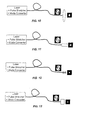
- Figs. 10-13 illustrate this, and show the modal image of the LP 02 mode in the HOM fiber, as well as a similar, but spatially contracted mode pattern after a collimating device following the fiber.
- Fig. 10 shows the use of a standard bulk-optic lens
- Fig. 11 shows the use of a fiber-based GRIN lens.
- Fig. 10 shows the use of a standard bulk-optic lens
- Fig. 11 shows the use of a fiber-based GRIN lens.
- the collimating element represents generically any one of a variety of beam shaping elements that can convert a complex spatial pattern into a Gaussian pattern.
- mode converters described in connection with Fig. 9 for converting the incoming, and optionally the outgoing, signals between modes are long period gratings
- the mode converters may be of any suitable design.
- the mode converting functionality may be achieved within the delivery fiber using in-fiber grating mode converters.
- holographic free-space mode converters, or tapered hollow-core fibers may be employed.
- a preferred means to obtain the mode-converting device functionality is with a broadband long period fiber grating (LPG).
- LPG may be induced in the HOM fiber itself, enabling a low cost, low loss, mode-converting device.
- Broadband mode converters are known that cover a wavelength range as large as 500 nm. For more details see S. Ramachandran, M. Yan, E. Monberg, F. Dimarcello, P. Wisk and S. Ghalmi, "Record bandwidth microbend gratings for spectrally flat variable optical attenuators," IEEE Photon. Tech. Lett., vol. 15, pp. 1561-1563, 2003 ; S. Ramachandran, US Patent No. 6,768,835 , both of which are incorporated by reference herein.
- the output from the short pulse device of the invention is propagated in free space, using standard collimating devices, it may also be coupled to other forms of media.
- the core region generally consists of silica doped with germanium at concentrations less than 10 wt% at the position of maximum index, and graded with radius to provide the shape desired.
- the center core is typically has a radius of less than 20 microns.
- the inner cladding region may be undoped, or lightly doped.
- Optical fibers as described above that are specially designed to support HOMs may be construed as meaning that a substantial portion, typically a predominant portion, of the optical energy propagating in the optical fiber is in a mode higher than the fundamental mode LP 01 .
- Preferred HOMs are LP02 through LP0, 10; and LP11 through LP1,10.
- pulse stretcher The element used to chirp the pulses, in the systems described here, is referred to as a pulse stretcher, which is a term familiar to those skilled in the art. For a another description of these elements see http://www- phys.llnl.gov/Organization/VDivision/Research/USP/USPFacilityVirtualTour/cpa.h tml incorporated herein by reference.
- the preferred choice of pulse stretchers are those operating on bulk optics, i.e. the optical pulses propagate through the stretching element. High-quality gratings and prisms are in this category.
- the operation of the devices described above relies in part on having relatively high dispersion in the HOM fiber. While the actual dispersion value will vary, the typical dispersion value will be less than (more negative than) -150 ps/nm-km.
- the length of the delivery fiber will in part be determined by the dispersion value. In a qualitative sense, that length is where the dispersion in the HOM fiber compensates for the nominal dispersion from the pulse stretcher that appears at the input of the HOM fiber, but before the optical pulses undergo significant non-linear distortion. That length is typically from 1-20 meters. It should be evident that this relatively short length distinguishes in the usual sense this fiber from a transmission fiber.
- the invention is preferably directed to devices where the pulses are femtosecond pulses (i.e. less than 1 picosecond), or shorter. In preferred embodiments the pulses are less than 200 femtoseconds.
Landscapes
- Physics & Mathematics (AREA)
- General Physics & Mathematics (AREA)
- Optics & Photonics (AREA)
- Chemical & Material Sciences (AREA)
- Dispersion Chemistry (AREA)
- Optical Modulation, Optical Deflection, Nonlinear Optics, Optical Demodulation, Optical Logic Elements (AREA)
- Optical Fibers, Optical Fiber Cores, And Optical Fiber Bundles (AREA)
- Manufacture, Treatment Of Glass Fibers (AREA)
- Lasers (AREA)
Applications Claiming Priority (1)
| Application Number | Priority Date | Filing Date | Title |
|---|---|---|---|
| US11/105,850 US20060233554A1 (en) | 2005-04-14 | 2005-04-14 | Optical fiber systems for delivering short high power pulses |
Publications (3)
| Publication Number | Publication Date |
|---|---|
| EP1712936A2 true EP1712936A2 (de) | 2006-10-18 |
| EP1712936A3 EP1712936A3 (de) | 2007-12-26 |
| EP1712936B1 EP1712936B1 (de) | 2012-08-22 |
Family
ID=36564051
Family Applications (1)
| Application Number | Title | Priority Date | Filing Date |
|---|---|---|---|
| EP06003432A Ceased EP1712936B1 (de) | 2005-04-14 | 2006-02-20 | Lichtleitfasersystem zum Bereitstellen von Hochleistungsimpulsen geringer Dauer |
Country Status (4)
| Country | Link |
|---|---|
| US (2) | US20060233554A1 (de) |
| EP (1) | EP1712936B1 (de) |
| JP (2) | JP2006295195A (de) |
| CN (1) | CN1901417B (de) |
Cited By (4)
| Publication number | Priority date | Publication date | Assignee | Title |
|---|---|---|---|---|
| EP1712936A3 (de) * | 2005-04-14 | 2007-12-26 | Furukawa Electric North America Inc. | Lichtleitfasersystem zum Bereitstellen von Hochleistungsimpulsen geringer Dauer |
| EP2082463A4 (de) * | 2006-10-26 | 2014-05-14 | Cornell Res Foundation Inc | System und verfahren zum erzeugen von optischen impulsen einer gewünschten wellenlänge unter verwendung von cherenkov-strahlung in fasern mit moden höherer ordnung |
| EP2745151A4 (de) * | 2011-08-15 | 2015-11-04 | Corning Inc | Mehrmodale optische fasern für multiplexing durch modusteilung |
| FR3118331A1 (fr) | 2020-12-23 | 2022-06-24 | Ilasis Laser | Système laser à fibre optique à impulsion picoseconde de forte énergie accordable en durée et utilisation d’un tel système laser |
Families Citing this family (26)
| Publication number | Priority date | Publication date | Assignee | Title |
|---|---|---|---|---|
| US7430352B2 (en) | 2005-07-29 | 2008-09-30 | Aculight Corporation | Multi-segment photonic-crystal-rod waveguides for amplification of high-power pulsed optical radiation and associated method |
| US7391561B2 (en) | 2005-07-29 | 2008-06-24 | Aculight Corporation | Fiber- or rod-based optical source featuring a large-core, rare-earth-doped photonic-crystal device for generation of high-power pulsed radiation and method |
| US7768700B1 (en) | 2006-11-30 | 2010-08-03 | Lockheed Martin Corporation | Method and apparatus for optical gain fiber having segments of differing core sizes |
| US7603038B1 (en) * | 2006-09-05 | 2009-10-13 | Los Alamos National Security, Llc | System and method that suppresses intensity fluctuations for free space high-speed optical communication |
| JP5250564B2 (ja) * | 2007-02-05 | 2013-07-31 | フルカワ エレクトリック ノース アメリカ インコーポレーテッド | 高次モード(hom)信号の伝播における有効断面積の連続的な増加 |
| US8428408B2 (en) | 2007-04-11 | 2013-04-23 | Furukawa Electric Co., Ltd. | Optical pulse reshaping device, optical pulse light source, super-continuum light generator and method for super-continuum light generation |
| US8179594B1 (en) | 2007-06-29 | 2012-05-15 | Lockheed Martin Corporation | Method and apparatus for spectral-beam combining of fanned-in laser beams with chromatic-dispersion compensation using a plurality of diffractive gratings |
| US7778498B2 (en) * | 2008-02-12 | 2010-08-17 | Ofs Fitel Llc | Systems and techniques for generating cylindrical vector beams |
| US7844146B2 (en) * | 2008-04-30 | 2010-11-30 | Ofs Fitel, Llc | All-fiber module for femtosecond pulse compression and supercontinuum generation |
| US8526110B1 (en) | 2009-02-17 | 2013-09-03 | Lockheed Martin Corporation | Spectral-beam combining for high-power fiber-ring-laser systems |
| CN101485558B (zh) * | 2009-02-27 | 2011-03-23 | 浙江工商大学 | 一种单光纤多光子荧光扫描内窥镜 |
| US8478134B2 (en) * | 2009-08-31 | 2013-07-02 | Ofs Fitel, Llc | Compression of generated optical continuum utilizing higher-order-mode fiber |
| US8503840B2 (en) | 2010-08-23 | 2013-08-06 | Lockheed Martin Corporation | Optical-fiber array method and apparatus |
| US8441718B2 (en) | 2009-11-23 | 2013-05-14 | Lockheed Martin Corporation | Spectrally beam combined laser system and method at eye-safer wavelengths |
| JP5729982B2 (ja) * | 2009-11-25 | 2015-06-03 | オーエフエス ファイテル,エルエルシー | 非線形光システム及び技術 |
| US8507877B2 (en) * | 2009-11-25 | 2013-08-13 | Ofs Fitel, Llc | Non-linear optical system and techniques |
| DE112011101288T5 (de) | 2010-04-12 | 2013-02-07 | Lockheed Martin Corporation | Strahldiagnostik- und Rückkopplungssystem sowie Verfahren für spektralstrahlkombinierteLaser |
| JP5805196B2 (ja) * | 2010-09-03 | 2015-11-04 | オーエフエス ファイテル,エルエルシー | 分散補償システム、および改善された性能指数を有する分散補償ファイバ |
| JP2014507682A (ja) | 2011-01-27 | 2014-03-27 | イムラ アメリカ インコーポレイテッド | 高ピーク出力光パルスのファイバ伝達のための方法およびシステム |
| FR2973957B1 (fr) * | 2011-04-05 | 2014-03-28 | Centre Nat Rech Scient | Oscillateur laser a fibre optique. |
| CN102904641B (zh) * | 2012-10-17 | 2015-07-08 | 江西省电力公司信息通信分公司 | 一种基于少模光纤的通信系统 |
| US9835778B1 (en) | 2013-09-13 | 2017-12-05 | Lockheed Martin Corporation | Apparatus and method for a diamond substrate for a multi-layered dielectric diffraction grating |
| US9366872B2 (en) | 2014-02-18 | 2016-06-14 | Lockheed Martin Corporation | Apparatus and method for fiber-laser output-beam shaping for spectral beam combination |
| CN108963734A (zh) * | 2018-07-05 | 2018-12-07 | 南开大学 | 一种涡旋光光纤激光器及其控制方法 |
| JP7497780B2 (ja) * | 2021-06-04 | 2024-06-11 | 日本電信電話株式会社 | 光ファイバ試験方法及び光ファイバ試験装置 |
| CN120255234B (zh) * | 2025-06-05 | 2025-08-05 | 中国人民解放军国防科技大学 | 激光强度低通滤波方法和装置 |
Family Cites Families (14)
| Publication number | Priority date | Publication date | Assignee | Title |
|---|---|---|---|---|
| US4360249A (en) * | 1979-10-17 | 1982-11-23 | Tetra-Tech, Inc. | Optical feedthrough for pressure vessels |
| US5862287A (en) * | 1996-12-13 | 1999-01-19 | Imra America, Inc. | Apparatus and method for delivery of dispersion compensated ultrashort optical pulses with high peak power |
| US6249630B1 (en) * | 1996-12-13 | 2001-06-19 | Imra America, Inc. | Apparatus and method for delivery of dispersion-compensated ultrashort optical pulses with high peak power |
| US6084996A (en) * | 1998-04-01 | 2000-07-04 | Lucent Technologies, Inc. | Broadband long-period gratings |
| US6327403B1 (en) * | 1999-06-10 | 2001-12-04 | Lasercomm Inc. | Reducing mode interference in transmission of LP02 Mode in optical fibers |
| US6665481B2 (en) * | 2001-12-20 | 2003-12-16 | Corning Incorporated | Low MPI dispersion compensating fiber |
| US20030185531A1 (en) * | 2002-03-26 | 2003-10-02 | Michael Lysiansky | High order mode dispersion compensating fiber |
| AU2003228254A1 (en) * | 2002-05-23 | 2003-12-12 | Rensselaer Polytechnic Institute | Detection of biospecific interactions using amplified differential time domain spectroscopy signal |
| US6768835B2 (en) * | 2002-09-04 | 2004-07-27 | Fitel Usa Corp | Tunable mode-converters using few mode fibers |
| JP4047232B2 (ja) * | 2003-06-18 | 2008-02-13 | 株式会社フジクラ | 高次モードファイバ用モード変換器 |
| US7184204B2 (en) * | 2003-07-01 | 2007-02-27 | Lambda Physik Ag | Master-oscillator power-amplifier (MOPA) excimer or molecular fluorine laser system with long optics lifetime |
| JP4823906B2 (ja) * | 2003-08-19 | 2011-11-24 | コーネル リサーチ ファンデーション インコーポレーティッド | 多光子顕微鏡観察、分光法、および内視鏡観察などの生物学的用途のための光ファイバー送集光システム |
| US20060233554A1 (en) * | 2005-04-14 | 2006-10-19 | Siddharth Ramachandran | Optical fiber systems for delivering short high power pulses |
| US7228029B1 (en) * | 2005-09-20 | 2007-06-05 | Furukawa Electric North America Inc. | Short pulse lasers using large mode area fibers and higher order modes |
-
2005
- 2005-04-14 US US11/105,850 patent/US20060233554A1/en not_active Abandoned
-
2006
- 2006-02-20 EP EP06003432A patent/EP1712936B1/de not_active Ceased
- 2006-03-28 CN CN2006100716939A patent/CN1901417B/zh not_active Expired - Fee Related
- 2006-04-14 JP JP2006111443A patent/JP2006295195A/ja active Pending
-
2009
- 2009-07-01 US US12/459,448 patent/US9417381B2/en not_active Expired - Fee Related
-
2010
- 2010-06-01 JP JP2010125795A patent/JP2010231229A/ja not_active Withdrawn
Non-Patent Citations (1)
| Title |
|---|
| None |
Cited By (6)
| Publication number | Priority date | Publication date | Assignee | Title |
|---|---|---|---|---|
| EP1712936A3 (de) * | 2005-04-14 | 2007-12-26 | Furukawa Electric North America Inc. | Lichtleitfasersystem zum Bereitstellen von Hochleistungsimpulsen geringer Dauer |
| EP2082463A4 (de) * | 2006-10-26 | 2014-05-14 | Cornell Res Foundation Inc | System und verfahren zum erzeugen von optischen impulsen einer gewünschten wellenlänge unter verwendung von cherenkov-strahlung in fasern mit moden höherer ordnung |
| EP2087400A4 (de) * | 2006-10-26 | 2014-05-14 | Cornell Res Foundation Inc | Erzeugung von optischen impulsen mit einer gewünschten wellenlänge unter verwendung der soliton-selbstfrequenzverschiebung in faser vom modus höherer ordnung |
| EP2745151A4 (de) * | 2011-08-15 | 2015-11-04 | Corning Inc | Mehrmodale optische fasern für multiplexing durch modusteilung |
| FR3118331A1 (fr) | 2020-12-23 | 2022-06-24 | Ilasis Laser | Système laser à fibre optique à impulsion picoseconde de forte énergie accordable en durée et utilisation d’un tel système laser |
| WO2022136290A1 (fr) | 2020-12-23 | 2022-06-30 | Ilasis Laser | Système laser à fibre optique à impulsion picoseconde de forte énergie accordable en durée et utilisation d'un tel système laser |
Also Published As
| Publication number | Publication date |
|---|---|
| EP1712936A3 (de) | 2007-12-26 |
| US20060233554A1 (en) | 2006-10-19 |
| US9417381B2 (en) | 2016-08-16 |
| JP2010231229A (ja) | 2010-10-14 |
| US20090274417A1 (en) | 2009-11-05 |
| CN1901417B (zh) | 2013-12-25 |
| EP1712936B1 (de) | 2012-08-22 |
| CN1901417A (zh) | 2007-01-24 |
| JP2006295195A (ja) | 2006-10-26 |
Similar Documents
| Publication | Publication Date | Title |
|---|---|---|
| US9417381B2 (en) | Optical fiber systems for delivering short high power pulses | |
| US6249630B1 (en) | Apparatus and method for delivery of dispersion-compensated ultrashort optical pulses with high peak power | |
| US8290317B2 (en) | Production of optical pulses at a desired wavelength utilizing higher-order-mode (HOM) fiber | |
| US5862287A (en) | Apparatus and method for delivery of dispersion compensated ultrashort optical pulses with high peak power | |
| JP5502362B2 (ja) | フェムト秒パルス圧縮およびスーパーコンティニューム生成用の全ファイバモジュール | |
| US8861073B2 (en) | Optical fiber delivery system for delivering optical short pulses and optical fiber delivery method | |
| JP5045161B2 (ja) | 光ファイバおよび広帯域光源 | |
| US20100061410A1 (en) | System and method for controlling nonlinearities in laser units | |
| US7817681B2 (en) | Pulse stretching optical fiber and related systems and methods | |
| Rastogi et al. | Design of large-mode-area three layered fiber structure for femtosecond laser pulse delivery | |
| US7228029B1 (en) | Short pulse lasers using large mode area fibers and higher order modes | |
| JP4816063B2 (ja) | 広帯域光源 | |
| US7483614B2 (en) | Optical fiber and optical device using the same | |
| US7440173B2 (en) | All fiber laser solution for spectral broadening and pulse stretching in a chirped pulse amplification fiber system | |
| EP1762868A1 (de) | Optische Faser und optische Vorrichtung damit | |
| Zhong et al. | Direct and low-loss connection between a hollow-core optical fiber and a dispersion compensating fiber for dispersion-free delivery of short optical pulses in hollow-core fiber | |
| Mishra et al. | Triangular Pulse Generation by a Normal Dispersion Silicon Core Single Mode Fiber | |
| Ramachandran et al. | High energy (nanojoule) femtosecond pulse delivery with highly dispersive higher order mode fibers | |
| Jespersen et al. | All-fiber higher-order-mode module with anomalous dispersion below 800 nm | |
| Nicholson | Applications of higher order modes in optical fibers to femtosecond pulses | |
| Ramachandran et al. | Robust, single-moded, broadband transmission and pulse compression in a record Aeff (2100 μm2) higher-order-mode fiber | |
| Nicholson et al. | Femtosecond pulse propagation and compression in 12 meters of 2100 μm2 effective area, higher-order-mode fiber |
Legal Events
| Date | Code | Title | Description |
|---|---|---|---|
| PUAI | Public reference made under article 153(3) epc to a published international application that has entered the european phase |
Free format text: ORIGINAL CODE: 0009012 |
|
| AK | Designated contracting states |
Kind code of ref document: A2 Designated state(s): AT BE BG CH CY CZ DE DK EE ES FI FR GB GR HU IE IS IT LI LT LU LV MC NL PL PT RO SE SI SK TR |
|
| AX | Request for extension of the european patent |
Extension state: AL BA HR MK YU |
|
| PUAL | Search report despatched |
Free format text: ORIGINAL CODE: 0009013 |
|
| AK | Designated contracting states |
Kind code of ref document: A3 Designated state(s): AT BE BG CH CY CZ DE DK EE ES FI FR GB GR HU IE IS IT LI LT LU LV MC NL PL PT RO SE SI SK TR |
|
| AX | Request for extension of the european patent |
Extension state: AL BA HR MK YU |
|
| 17P | Request for examination filed |
Effective date: 20080527 |
|
| 17Q | First examination report despatched |
Effective date: 20080627 |
|
| AKX | Designation fees paid |
Designated state(s): DE FR GB |
|
| GRAP | Despatch of communication of intention to grant a patent |
Free format text: ORIGINAL CODE: EPIDOSNIGR1 |
|
| GRAS | Grant fee paid |
Free format text: ORIGINAL CODE: EPIDOSNIGR3 |
|
| GRAA | (expected) grant |
Free format text: ORIGINAL CODE: 0009210 |
|
| AK | Designated contracting states |
Kind code of ref document: B1 Designated state(s): DE FR GB |
|
| REG | Reference to a national code |
Ref country code: GB Ref legal event code: FG4D |
|
| REG | Reference to a national code |
Ref country code: DE Ref legal event code: R096 Ref document number: 602006031530 Country of ref document: DE Effective date: 20121018 |
|
| PLBE | No opposition filed within time limit |
Free format text: ORIGINAL CODE: 0009261 |
|
| STAA | Information on the status of an ep patent application or granted ep patent |
Free format text: STATUS: NO OPPOSITION FILED WITHIN TIME LIMIT |
|
| 26N | No opposition filed |
Effective date: 20130523 |
|
| REG | Reference to a national code |
Ref country code: DE Ref legal event code: R097 Ref document number: 602006031530 Country of ref document: DE Effective date: 20130523 |
|
| REG | Reference to a national code |
Ref country code: FR Ref legal event code: PLFP Year of fee payment: 11 |
|
| REG | Reference to a national code |
Ref country code: FR Ref legal event code: PLFP Year of fee payment: 12 |
|
| REG | Reference to a national code |
Ref country code: FR Ref legal event code: PLFP Year of fee payment: 13 |
|
| PGFP | Annual fee paid to national office [announced via postgrant information from national office to epo] |
Ref country code: FR Payment date: 20210325 Year of fee payment: 16 |
|
| PGFP | Annual fee paid to national office [announced via postgrant information from national office to epo] |
Ref country code: DE Payment date: 20210329 Year of fee payment: 16 Ref country code: GB Payment date: 20210329 Year of fee payment: 16 |
|
| REG | Reference to a national code |
Ref country code: DE Ref legal event code: R119 Ref document number: 602006031530 Country of ref document: DE |
|
| GBPC | Gb: european patent ceased through non-payment of renewal fee |
Effective date: 20220220 |
|
| PG25 | Lapsed in a contracting state [announced via postgrant information from national office to epo] |
Ref country code: FR Free format text: LAPSE BECAUSE OF NON-PAYMENT OF DUE FEES Effective date: 20220228 |
|
| PG25 | Lapsed in a contracting state [announced via postgrant information from national office to epo] |
Ref country code: GB Free format text: LAPSE BECAUSE OF NON-PAYMENT OF DUE FEES Effective date: 20220220 Ref country code: DE Free format text: LAPSE BECAUSE OF NON-PAYMENT OF DUE FEES Effective date: 20220901 |