EP1712393A2 - Schutzhaube, insbesondere für Kraftfahrzeuge - Google Patents
Schutzhaube, insbesondere für Kraftfahrzeuge Download PDFInfo
- Publication number
- EP1712393A2 EP1712393A2 EP06006280A EP06006280A EP1712393A2 EP 1712393 A2 EP1712393 A2 EP 1712393A2 EP 06006280 A EP06006280 A EP 06006280A EP 06006280 A EP06006280 A EP 06006280A EP 1712393 A2 EP1712393 A2 EP 1712393A2
- Authority
- EP
- European Patent Office
- Prior art keywords
- protective hood
- holding element
- hood according
- edge
- protective
- Prior art date
- Legal status (The legal status is an assumption and is not a legal conclusion. Google has not performed a legal analysis and makes no representation as to the accuracy of the status listed.)
- Granted
Links
Images


Classifications
-
- B—PERFORMING OPERATIONS; TRANSPORTING
- B60—VEHICLES IN GENERAL
- B60J—WINDOWS, WINDSCREENS, NON-FIXED ROOFS, DOORS, OR SIMILAR DEVICES FOR VEHICLES; REMOVABLE EXTERNAL PROTECTIVE COVERINGS SPECIALLY ADAPTED FOR VEHICLES
- B60J11/00—Removable external protective coverings specially adapted for vehicles or parts of vehicles, e.g. parking covers
- B60J11/06—Removable external protective coverings specially adapted for vehicles or parts of vehicles, e.g. parking covers for covering only specific parts of the vehicle, e.g. for doors
-
- B—PERFORMING OPERATIONS; TRANSPORTING
- B62—LAND VEHICLES FOR TRAVELLING OTHERWISE THAN ON RAILS
- B62D—MOTOR VEHICLES; TRAILERS
- B62D25/00—Superstructure or monocoque structure sub-units; Parts or details thereof not otherwise provided for
- B62D25/20—Floors or bottom sub-units
- B62D25/2072—Floor protection, e.g. from corrosion or scratching
Definitions
- the invention relates to a protective hood, in particular for motor vehicles, which is formed from a sheet material and which is adapted to an outer overall shape or the shape of individual parts of an object to be protected and at least their edges are held on the object to be protected, along at least one edge of the protective hood , which is associated with a body edge of the object to be protected, a holding element is provided which engages in a holding position under pretension on the body edge of the object to be protected, wherein the holding element is directly connected to the protective hood.
- Protective hoods of this kind are particularly suitable for the preventive protection of both the surface against abrasive or chemical emission, such as dust, rust, bird droppings, condensation and waterlogging and penetrating moisture, as well as against mechanical damage, such as scratching and grinding damage and resulting damage to stationary, Storage and transport times provided.
- a protective hood for motor vehicles in which in the region of body edges of the motor vehicles to be protected on the protective cover a pocket is sewn, in which a flat strip-shaped element can be inserted, which acts in a holding position under bias on the body edge of the object to be protected.
- the guard is indeed tense and prevents air from entering the body edges, such as the wheel arches, but the sewing of the pockets and the introduction of the moldings in the bag is an additional Arbelts suits.
- the holding element is formed from the material or from the base material of the protective hood and is connected to the protective hood by sewing or welding.
- the holding element is formed from a plurality of interconnected layers of a polyester fleece.
- the polyester fleece is pressed in a first step in the form, then cut or punched and optionally sewn together the items or per Ultrasound welded.
- the retaining element produced in this way is connected to the protective hood.
- the object of the invention is therefore to provide a protective cover with firmly connected holding elements, in which the production of the holding element is carried out with fewer steps.
- the retaining elements to be connected to the protective cover made of a thermoplastic material, preferably a polyolefin.
- the material of the holding elements of an abrasion-resistant modified polyolefin having a Shore hardness in the range of 40 to 70 D, preferably with a Shore hardness of 62 +/- 3D.
- Material options may be in particular: polypropylene, polyethylene or a polypropylene / polyethylene mixture, 'wherein the Shore hardness and the temperature resistance is matched to the application holding element.
- the density of the material is preferably in the range of 0.90 to 1.0 g / cm 3 , in particular, the density is 0.97 g / cm 3 .
- the yield stress of the material is in the range of 18 to 28 MPa, preferably 23 +/- 2 MPa.
- the temperature range of use of the material should be in the range of -60 ° C to +150 ° C, at least in the range of -60 ° C to + 95 ° C.
- the holding element has rounded edges in order to avoid mechanical damage to the vehicle surfaces.
- a holding element can be produced by means of CNC milling, in which preferably the edges are already rounded.
- Other punching or cutting methods, such as water jet or laser cutting are conceivable, in which case the edges must be rounded in a subsequent step.
- the holding element has, according to an advantageous embodiment, a thickness in the range of 0.5 to 2.00 mm, preferably of 1.5 +/- 0.3 mm.
- the retaining element is sewn or welded to the protective hood. It is advantageous to carry out that the seam width during sewing is 5 to 20 mm, preferably 8 to 10 mm. When welding, ultrasonic welding methods are preferably used.
- the body edges of the motor vehicle, on which holding elements of the protective hood are provided may be, for example, the wheel arches and / or the hood edge and / or the door edges of the motor vehicle.
- the holding element preferably has a rectangular or triangular cross-section and is designed to be flexible in bending.
- the holding element is integrally formed.
- the one-piece shape has the advantage that the kausschwulste occurring in the multi-part retaining elements, which can be unstable the moldings or show so-called breakages, are avoided and thus a smooth folding function is ensured.
- An embodiment of the retaining element provides that the retaining element is greater in width than a folded edge of the body edge, for example, the wheel arches or the hood edge, is. This design allows safe positioning of the guard and prevents self-loosening by trailing air.
- the holding element has a radius of curvature which is greater than the radius or the curvature of the body edge of the vehicle or a vehicle part, whereby a folding effect for fixing the holding element is achieved at the body edge.
- the difference between the radius of curvature and the curvature of the body edge is increased. This can be achieved that even at higher speeds during transport, such as on a train or while driving the motor vehicle, a safe investment of the protective hood, at least in the section of the attachment is given.
- the material of the protective cover is designed such that it is impermeable to water and dust from the outside inwards to the protective object. In order to prevent condensation on the surface of the object to be protected, however, it should be permeable to air and water vapor at least from the inside to the outside.
- at least one layer of nonwoven fabric made of synthetic and / or natural and / or semi-synthetic staple fibers is provided as the base material of the protective hood.
- a polymer coating is provided on the outside of the base material or a film of polymer materials is laminated on.
- Fig. 1 shows a protective hood 1, which is mounted on a motor vehicle.
- This protective hood is designed, for example, in one piece and, depending on the customer's wishes, has different trimming areas 3, 4, 6, 7.
- the protective cover 1 is made according to the embodiment of one or more layers of nonwoven fabric made of synthetic staple fibers, which has on its side facing away from the motor vehicle side a polymer coating.
- Suitable polymers include polypropylenes, polyethylenes, polyethersulfones (PES), polyamides, but also other polymers are conceivable.
- the solidification of the nonwoven fabric is carried out by needling, water jet technology or thermally or combinations thereof.
- the protective hood 1 further comprises front and rear Radlaufabdeckungen 9, which are adapted to the shape of the fender and the course of the body edge 10 of the Radlaufs. At the body edges 10 is a fixation, as described below.
- the holding element 11 is a preferably flat strip-shaped part which has a curved shape. This curved shape or a sickle-like course of the holding element 11 can be seen for example in FIG.
- the wall thickness comprises a few millimeters, for example 1.5 mm
- the width is usually 2 to 15 cm, in particular 5 to 10 cm, adapted to the size of the vehicle wheel arch or according to the vehicle size, so that the holding member 11 to the Body edge 10 can be placed so that it engages in a holding position 12 ( Figure 4) under pretension on the body edge 10 of the object to be protected.
- the holding element 11 consists of a modified abrasion resistant polyolefin and is sewn or welded to the protective hood. It is produced in one piece, wherein different manufacturing processes, such as milling, injection molding, stamping or cutting with optionally subsequent deburring or rounding of the edges, can be used.
- the material of the holding element preferably has a Shore hardness of about 62 D, a density of about 0.97 g / cm 3 , an elongation at break of 538% and a yield stress of 23 MPa.
- the temperature range is at least -60 ° C to + 95 ° C.
- the length of the holding element 11 is adapted to the respective wheel arch of the motor vehicle to be protected.
- the connection with the protective cover 1 via the seam 13 whose width is 5 to 20 mm, preferably 8 to 10 mm.
- the curvature radius of the holding element 11 can also be adjusted to the radius of curvature of the body edge 10 via the notch 14 (FIG. 2 a) of the holding element 11 be adjusted.
- FIGS. 3, 4 show a section along the line I-I.
- the holding element 11 After mounting the protective cover 1 on the motor vehicle, the holding element 11 is arranged in the starting position shown in FIG. 3.
- the retaining element 11 For fixing the wheel arch cover 9 (FIG. 1) on the body edge 10, the retaining element 11 is folded inwards in accordance with arrow 15, so that the free end of the retaining element 11 faces the wheel arch.
- the holding element 11 is under prestress with a force according to arrow 16 on the folded edge 14 of the wheel arch.
- the removal of the protective cover 1 requires - apart from possibly further clamping elements - only a folding back of the retaining element 11 from its holding position 12 in the starting position 18th
- the protective hood 1 can have a trimming area 3, so that when the vehicle is moving the view towards the outside for the driver is given.
- another retaining element 21 is sewn to the edge 22 of the protective hood 1 or welded ( Figure 5)
- the holding element 21 is also made according to the invention of a polyolefin with the aforementioned properties and is pushed under the hood of the motor vehicle.
- a seal and attachment between guard 1 and motor vehicle is achieved.
- the holding element 21 and the protective hood 1 are shaped so that the spray nozzle areas of the vehicle are exposed, so that the function of the spray nozzles is given on the transport path or when the vehicle is mounted with the protective hood 2 mounted.
- retaining elements according to the invention are all areas of the protective hood in which, for example, so-called trimming areas 4, 6 can lead to leaks or to the inflation of the protective hood 1.
Landscapes
- Engineering & Computer Science (AREA)
- Mechanical Engineering (AREA)
- Chemical & Material Sciences (AREA)
- Combustion & Propulsion (AREA)
- Transportation (AREA)
- Superstructure Of Vehicle (AREA)
- Motor Or Generator Frames (AREA)
Abstract
Description
- Die Erfindung betrifft eine Schutzhaube, insbesondere für Kraftfahrzeuge, die aus einem Flächenmaterial gebildet ist und die einer äußeren Gesamtform oder der Form einzelner Teile eines zu schützenden Objektes angepasst ist und zumindest deren Ränder am zu schützenden Objekt gehalten sind, wobei entlang zumindest eines Randes der Schutzhaube, welcher einer Körperkante des zu schützenden Objektes zugeordnet ist, ein Halteelement vorgesehen ist, das in einer Halteposition unter Vorspannung an der Körperkante des zu schützenden Objektes angreift, wobei das Halteelement unmittelbar mit der Schutzhaube verbunden ist.
- Derartige Schutzhauben sind besonders zum präventivem Schutz sowohl der Oberfläche gegen abrasive oder chemische Emission, wie Staub, Flugrost, Vogelkot, Kondensations- und Staunässe und eindringende Nässe als auch gegen mechanische Beschädigungen, wie beispielsweise Kratz- und Schleifschäden und daraus resultierende Schäden bei Stand-, Lager- und Transportzeiten vorgesehen.
- Aus der
DE 203 06 825 U1 ist eine Schutzhaube für Kraftfahrzeuge bekannt, bei welcher im Bereich von Körperkanten der zu schützenden Kraftfahrzeuge an der Schutzhaube eine Tasche angenäht ist, in der ein flach streifenförmiges Element eingefügt werden kann, das in einer Halteposition unter Vorspannung an der Körperkante des zu schützenden Objektes angreift. Damit wird die Schutzhaube zwar gespannt und ein Eindringen von Luft im Bereich der Körperkanten, beispielsweise der Radläufe vermieden, jedoch ist das Nähen der Taschen und das Einbringen der Formteile in die Tasche ein zusätzlicher Arbeltsschritt. - Des Weiteren ist in der
DE 203 19 938 U1 eine Schutzhaube beispielsweise für Kraftfahrzeuge beschrieben, bei der das Halteelement aus dem Material oder aus dem Grundmaterial der Schutzhaube gebildet ist und mit der Schutzhaube durch annähen oder verschweißen verbunden ist. Speziell ist angegeben, dass das Halteelement aus mehreren, miteinander verbundenen Schichten eines Polyestervlieses gebildet ist. Zur Herstellung solcher Halteelemente bzw. von Schutzhauben mit solchen Haltelementen sind mehrere Arbeitsschritte notwendig. Das Polyestervlies wird in einem ersten Schritt in Form verpresst, danach geschnitten bzw. gestanzt und gegebenenfalls die Einzelteile zusammengenäht oder per Ultraschall verschweißt. In einem letzten Schritt wird das so gefertigte Halteelement mit der Schutzhaube verbunden. - Die Aufgabe der Erfindung ist es nun, eine Schutzhaube mit fest verbundenen Haltelementen zu schaffen, bei der die Herstellung des Haltelementes mit weniger Arbeitsschritten durchgeführt wird.
- Die Aufgabe wird mit den Merkmalen des Schutzanspruchs 1 gelöst. Vorteilhafte Aus- und Weiterbildungen sind in den Unteransprüchen dargestellt.
- Gemäß der Erfindung ist vorgesehen, die mit der Schutzhaube zu verbindenden Halteelemente aus einem thermoplastischen Material, vorzugsweise aus einem Polyolefin herzustellen. Nach einer vorteilhaften Ausbildung der Erfindung besteht das Material der Halteelemente aus einem abriebfest modifizierten Polyolefin mit einer Shorehärte im Bereich von 40 bis 70 D, vorzugsweise mit einer Shorehärte von 62 +/- 3D. Materialmöglichkeiten können insbesondere sein: Polypropylen, Polyethylen bzw. ein Polypropylen/Polyethylen Gemisch,'wobei die Shorehärte sowie die Temperaturbeständigkeit entsprechend auf die Anwendung Halteelement abgestimmt wird.
- Die Dichte des Materials liegt vorzugsweise im Bereich von 0,90 bis 1,0 g/cm3, insbesondere beträgt die Dichte 0,97g/cm3.
- Nach einer Ausbildung des Materials liegt dessen Reißdehnung im Bereich von 400 bis 700%, insbesondere bei 538 +/-40%. Die Streckspannung des Materials liegt im Bereich von 18 bis 28 MPa, vorzugsweise bei 23 +/-2MPa.
- Der Temperatureinsatzbereich des Materials sollte im Bereich von -60 °C bis +150 °C, zumindest im Bereich von -60 °C bis + 95°C liegen.
- Nach einer vorteilhaften Ausbildung der Erfindung weist das Halteelement verrundete Kanten auf, um eine mechanische Beschädigung der Fahrzeugoberflächen zu vermeiden. Ein solches Haltelement kann mittels CNC-Fräsverfahren hergestellt werden, bei dem vorzugsweise die Kanten bereits verrundet werden. Auch andere Stanz- oder Schneidverfahren, beispielsweise Wasserstrahl- oder Laserschneiden sind denkbar, wobei hier in einem nachfolgenden Schritt die Kanten verrundet werden müssen. Es ist jedoch auch denkbar die Halteelemente durch Spritzgießen oder Vakuumformung, beispielsweise Tiefziehen, herzustellen.
- Das Halteelement weist nach einer vorteilhaften Ausbildung eine Dicke im Bereich von 0,5 bis 2,00 mm, vorzugsweise von 1,5 +/-0,3mm auf.
- Gemäß der Erfindung ist das Halteelement an der Schutzhaube angenäht oder angeschweißt. Dabei ist vorteilhaft auszuführen, dass die Nahtbreite beim Nähen 5 bis 20 mm, vorzugsweise 8 bis 10 mm beträgt. Beim Anschweißen kommen vorzugsweise Ultraschallschweißverfahren zum Einsatz.
- Die Körperkanten des Kraftfahrzeuges, an denen Halteelemente der Schutzhaube vorgesehen sind, können beispielsweise die Radläufe und/oder die Motorhaubenkante und/oder die Türkanten des Kraftfahrzeuges sein.
- Das Halteelement weist vorzugsweise einen rechteckigen oder dreieckigen Querschnitt auf und ist biegeelastisch ausgebildet.
- Gemäß einer vorteilhaften Ausbildung der Erfindung ist das Halteelement einteilig ausgebildet. Gegenüber mehrteiligen Ausführungen von Halteelementen, wie sie beispielsweise aus der
DE 203 19 938 U1 bekannt sind, hat die einteilige Form den Vorteil, dass die bei den mehrteiligen Halteelementen auftretenden Verbindungsschwulste, die die Formteile labil werden lassen oder so genannte Bruchstellen aufzeigen, vermieden werden und somit eine leichtgängige Klappfunktion gewährleistet wird. - Eine Ausbildung des Halteelementes sieht vor, dass das Halteelement in seiner Breite größer ist als eine Umkantung der Körperkante, beispielsweise der Radläufe oder der Motorhaubenkante, ist. Diese Ausbildung ermöglicht ein sicheres Positionieren der Schutzhaube und verhindert ein selbständiges Lösen durch hinterströmende Luft.
- Weiterhin kann vorgesehen sein, dass das Halteelement einen Krümmungsradius aufweist, der größer als der Radius oder der Krümmungsverlauf der Körperkante des Fahrzeuges oder eines Fahrzeugteils, wodurch ein Klappeffekt zur Fixierung des Halteelementes an der Körperkante erzielt wird.
- Vorteilhafterweise ist vorgesehen, dass bei einer Erhöhung der Haltekraft durch die Vorspannung des flach streifenförmigen Halteelementes die Differenz zwischen dem Krümmungsradius und des Krümmungsverlaufes der Körperkante erhöht wird. Dadurch kann erzielt werden, dass selbst bei höheren Fahrtgeschwindigkeiten während des Transportes, wie beispielsweise auf einem Zug oder während der Fahrt des Kraftfahrzeuges eine sichere Anlage der Schutzhaube, zumindest im Abschnitt der Befestigung, gegeben ist.
- Das Material der Schutzhaube ist derart ausgebildet, dass es von außen nach innen zum schützenden Objekt wasser- und staubundurchlässig ist. Um eine Kondensatbildung auf der Oberfläche des zu schützenden Objektes zu verhindern, sollte es jedoch zumindest von innen nach außen luft- und wasserdampfdurchlässig sein. Vorzugsweise ist als Grundmaterial der Schutzhaube wenigstens eine Lage Vliesstoff aus synthetischen und/oder natürlichen und/oder halbsynthetischen Stapelfasern vorgesehen. Vorzugsweise ist außenseitig auf dem Grundmaterial eine Polymerbeschichtung vorgesehen oder es ist eine Folie aus Polymerstoffen auflaminiert.
- Nachfolgend wird die Erfindung anhand von Ausführungsbeispielen näher beschrieben. Die zugehörigen Zeichnungen zeigen:
- Fig. 1
- eine perspektivische Ansicht eines Kraftfahrzeuges mit einer Schutzhaube,
- Fig. 2
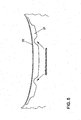
- die Anordnung eines Halteelementes an einem Radlauf eines Kraftfahrzeuges,
- Fig. 2a
- ein für einen Radlauf vorgesehenes Halteelement,
- Fig. 3
- eine Anordnung eines Halteelementes an einem Radlauf vor der Festlegung an der Körperkante,
- Fig. 4
- eine Anordnung eines Halteelementes an einem Radlauf nach der Festlegung und
- Fig. 5
- ein Haltelement zur Festlegung der Schutzhaube an einer Körperkante einer Motorhaube eines Kraftfahrzeuges
- Fig. 1 zeigt eine Schutzhaube 1, die auf ein Kraftfahrzeug aufgezogen ist. Diese Schutzhaube ist beispielsweise einteilig ausgebildet und weist je nach Kundenwunsch unterschiedliche Beschnittbereiche 3,4,6,7 auf.
- Die Schutzhaube 1 ist gemäß dem Ausführungsbeispiel aus einer oder mehreren Lagen Vliesstoff aus synthetischen Stapelfasern hergestellt, der an seiner vom Kraftfahrzeug abgewandten Seite eine Polymerbeschichtung aufweist. Als Polymere kommen in Betracht Polypröpylen, Polyäthylen, Polyethersulfone (PES), Polyamide, aber auch andere Polymere sind denkbar. Die Verfestigung des Vliesstoffes erfolgt durch Nadeln, Wasserstrahltechnik oder thermisch bzw. Kombinationen hieraus.
- Die Schutzhaube 1 umfasst weiterhin vordere und hintere Radlaufabdeckungen 9, die an die Form des Kotflügels und den Verlauf der Körperkante 10 des Radlaufs angepasst sind. An den Körperkanten 10 erfolgt eine Fixierung, wie im Folgenden beschrieben.
- Durch die Anpassung der Radlaufabdeckung sind die Räder des Kraftfahrzeuges frei zugänglich. Als Fixierung der Radiaufabdeckungen 9 am Radlauf sind Haltelemente 11 vorgesehen, wie in Fig.2 bis 4 dargestellt. Das Halteelement 11 ist ein vorzugsweise flaches streifenförmiges Teil, das eine gekrümmte Form aufweist. Diese gekrümmte Form oder ein sichelähnlicher Verlauf des Halteelementes 11 geht beispielsweise aus Fig. 2 hervor. Während die Wandstärke wenige Millimeter, beispielsweise 1,5 mm, umfasst, beträgt die Breite üblicherweise 2 bis 15 cm, insbesondere 5 bis 10 cm, angepasst an die Größe des Fahrzeug-Radlaufes bzw. entsprechend der Fahrzeuggröße, so dass das Haltelement 11 um die Körperkante 10 so herumgelegt werden kann, dass es in einer Halteposition 12 (Fig.4) unter Vorspannung an der Körperkante 10 des zu schützenden Objektes angreift.
- Das Haltelement 11 gemäß der Erfindung besteht aus einem äbreibfest modifizierten Polyolefin und ist an der Schutzhaube angenäht oder angeschweißt. Es wird einteilig hergestellt, wobei unterschiedliche Herstellungsverfahren, wie Fräsen, Spritzgussverfahren, Stanzen oder Schneiden mit gegebenenfalls anschließenden Entgraten oder Verrunden der Kanten, zur Anwendung kommen können.
- Das Material des Haltelementes weist vorzugsweise eine Shorehärte von ca. 62 D, eine Dichte von ca. 0,97 g/cm3, eine Reißdehnung von 538 % und eine Streckspannung von 23 MPa auf. Der Temperatureinsatzbereich liegt bei zumindest -60 °C bis + 95 °C.
- Die Länge des Halteelementes 11 ist an den jeweiligen Radlauf des zu schützenden Kraftfahrzeuges angepasst. Die Verbindung mit der Schutzhaube 1 erfolgt über die Naht 13, deren Breite 5 bis 20 mm, vorzugsweise 8 bis 10 mm beträgt.
- Das Halteelement 11 ist in seiner Breite größer als eine Umkantung 14 der Körperkante 10. Beim Befestigen des Halteelementes 11 an der Schutzhaube 1 kann zudem der Krümmungsradius des Haltelementes 11 auf den Krümmungsradius der Körperkante 10 über die Einkerbung 14 (Fig. 2a) des Halteelementes 11 angepasst werden.
- In den Fig. 3, 4 ist ein Schnitt entlang der Linie I - I dargestellt. Nach dem Aufziehen der Schutzhaube 1 auf das Kraftfahrzeug ist das Halteelement 11 in der in der Fig. 3 dargestellten Ausgangsposition angeordnet. Zur Fixierung der Radlaufabdeckung 9 (Fig.1) an der Körperkante 10 wird das Halteelement 11 gemäß Pfeil 15 nach innen geklappt, so dass das freie Ende des Halteelementes 11 zum Radkasten zeigt. Damit liegt das Halteelement 11 unter Vorspannung mit einer Kraft gemäß Pfeil 16 an der Umkantung 14 des Radlaufes an. Das Abnehmen der Schutzhaube 1 erfordert - abgesehen von eventuell weiteren Spannelementen - lediglich ein Zurückklappen des Halteelementes 11 aus seiner Halteposition 12 in die Ausgangsposition 18.
- Wie bereits aus der
DE 203 06 825 U1 vorbekannt, wird auf Grund der Positionierung des Halteelementes 11 mit einem geringeren Radius über die Einkerbung 14 als dessen Ausgangszustand ein Klappeffekt erzielt, der neben der Fixierung auch eine Zentrierung und eine ständige Anpassung der Halterung an den Radlauf ermöglicht. Dadurch wird die Schutzhaube 1 ebenfalls stärker angespannt und ein zusätzliches Aufblähen der Schutzhaube weitestgehend unterbunden. - Gemäß Fig. 1 kann die Schutzhaube 1 einen Beschnittbereich 3 aufweisen, damit bei Bewegung des Fahrzeugs die Sicht nach außen für den Fahrer gegeben ist. Um ein Abheben bzw. Flattern der Schutzhaube 1 in diesem Bereich zu verhindern und eine Dichtigkeit, insbesondere gegen Schmutz- und Wasser sowie eindringen von Fahrtwind, zwischen der Schutzhaube und des Fahrzeuges herzustellen, ist ein weiteres Halteelement 21 an der Kante 22 der Schutzhaube 1 angenäht oder geschweißt (Fig.5) Das Halteelement 21 besteht gemäß der Erfindung ebenfalls aus einem Polyolefin mit den bereits genannten Eigenschaften und wird unter die Motorhaube des Kraftfahrzeuges geschoben. Somit wird eine Abdichtung und Befestigung zwischen Schutzhaube 1 und Kraftfahrzeug erreicht. Gemäß dem Ausführungsbeispiel sind das Haltelement 21 und die Schutzhaube 1 so geformt, dass die Spritzdüsenbereiche des Fahrzeuges freigelegt sind, so dass die Funktion der Spritzdüsen auf dem Transportweg bzw. beim Fahren des Fahrzeuges mit montierter Schutzhaube 2 gegeben ist.
- Weitere Einsatzmöglichkeiten der erfindungsgemäßen Halteelemente sind alle Bereiche der Schutzhaube, bei denen es beispielsweise durch so genannte Beschnittbereiche 4,6 zu Undichtigkeiten oder zum Aufblähen der Schutzhaube 1 kommen kann.
Claims (22)
- Schutzhaube (1), insbesondere für Kraftfahrzeuge, die aus einem Flächenmaterial gebildet ist und die einer äußeren Gesamtform oder der Form einzelner Teile eines zu schützenden Objektes angepasst ist und zumindest deren Ränder am zu schützenden Objekt gehalten sind, wobei entlang zumindest eines Randes der Schutzhaube (1), welcher einer Körperkante (10,22) des zu schützenden Objektes zugeordnet ist, ein Halteelement (11,21) vorgesehen ist, das in einer Halteposition (17) unter Vorspannung an der Körperkante (11,21) des zu schützenden Objektes angreift, wobei das Halteelement (11,21) unmittelbar mit der Schutzhaube verbunden ist, dadurch gekennzeichnet, dass das Halteelement (11,21) nicht aus dem Flächenmaterial der Schutzhaube selbst gebildet und aus einem thermoplastischen Material, vorzugsweise aus einem Polyolefin ist.
- Schutzhaube nach Anspruch 1, dadurch gekennzeichnet, dass das Halteelement (11,21) eine Dicke von 0,5 bis 2,00 mm, vorzugsweise von 1,5 mm aufweist.
- Schutzhaube nach Anspruch 1 oder 2, dadurch gekennzeichnet, dass das Haltelement (11,21) verrundete Kanten aufweist.
- Schutzhaube nach einem der Ansprüche 1 bis 3, dadurch gekennzeichnet, dass das Haltelement (11,21) an der Schutzhaube (1) angenäht ist.
- Schutzhaube nach Anspruch 4, dadurch gekennzeichnet, dass die Nahtbreite 5 bis 20 mm, vorzugsweise 8-10 mm beträgt.
- Schutzhaube nach einem der Ansprüche 1 bis 3, dadurch gekennzeichnet, dass das Halteelement (11,21) an die Schutzhaube (1), vorzugsweise mittels Ultraschallschweißverfahren, angeschweißt ist.
- Schutzhaube nach einem der Ansprüche 1 bis 6, dadurch gekennzeichnet, dass das Halteelement (11,21) durch Fräsen oder Spritzgussverfahren hergestellt ist.
- Schutzhaube nach einem der Ansprüche 1 bis 6, dadurch gekennzeichnet, dass das Halteelement (11,21) durch Stanzen oder Schneiden, vorzugsweise Wasserstrahlschneiden oder Laserschneiden, und gegebenenfalls anschließenden Kantenbrechen oder Entgraten hergestellt ist.
- Schutzhaube nach einem der Ansprüche 1 bis 8, dadurch gekennzeichnet, dass die Körperkante (10,22) des zu schützenden Objektes ein Radlauf und/oder eine Motorhaubenkante und/oder eine Türkante eines Kraftfahrzeuges ist.
- Schutzhaube nach einem der Ansprüche 1 bis 9, dadurch gekennzeichnet, dass das Halteelement (11,21) einteilig ausgebildet ist.
- Schutzhaube nach einem der Ansprüche 1 bis 10, dadurch gekennzeichnet, dass das Halteelement (11,21) in seiner Breite größer als eine Umkantung der Körperkante (10,22) ist.
- Schutzhaube nach einem der Ansprüche 1 bis 11, dadurch gekennzeichnet, dass das Haltelement (11) einen Krümmungsradius aufweist, der größer als der Radius oder Krümmungsverlauf der Körperkante (10) ist.
- Schutzhaube nach einem der Ansprüche 1 bis 12, dadurch gekennzeichnet, dass bei einer Erhöhung der Haltekraft des Halteelementes (11) an der Körperkante (10) die Differenz zwischen dem Krümmungsradius des Halteelementes (11) und des Krommungsverlaufes der Körperkante (10) erhöht ist.
- Schutzhaube nach einem der Ansprüche 1 bis 13, dadurch gekennzeichnet, dass das Halteelement (11,21) biegeelastische Eigenschaften aufweist.
- Schutzhaube nach einem der Ansprüche 1 bis 14, dadurch gekennzeichnet, dass das Material der Schutzhaube (1) luft-, wasserdampfdurchlässig sowie wasserabweisend und staubundurohlässig ist.
- Schutzhaube nach Anspruch 15, dadurch gekennzeichnet, dass das Material der Schutzhaube (1) aus wenigstens einer Lage Vliesstoff aus synthetischen und/oder natürlichen und/oder halbsynthetischen Stapelfasern gebildet ist.
- Schutzhaube nach Anspruch 16, dadurch gekennzeichnet, dass die Schutzhaube (1) außenseitig eine Polymerbeschichtung aufweist oder mit einer Folie aus Polymerstoffen laminiert ist.
- Schutzhaube nach einem der Ansprüche 1 bis 17, dadurch gekennzeichnet, dass das Material des Haltelementes (11,21) ein abriebfest modifiziertes Polyolefin mit einer Shorehärte im Bereich von 40 bis 70 D, vorzugsweise mit einer Shorehärte von 62 D, ist.
- Schutzhaube nach einem der Ansprüche 1 bis 18, dadurch gekennzeichnet, dass das Material des Halteelementes (11,21) eine Dichte im Bereich von 0, 90 bis 1,0 g/cm3, vorzugsweise 0,97 g/cm3, aufweist.
- Schutzhaube nach einem der Ansprüche 1 bis 19, dadurch gekennzeichnet, dass das Material des Halteelementes (11,21) eine Reißdehnung im Bereich von 400 bis 700 %, insbesondere von 538 %, aufweist.
- Schutzhaube nach einem der Ansprüche 1 bis 20, dadurch gekennzeichnet, dass das Material des Halteelementes (11,21) eine Streckspannung im Bereich von 18 bis 28 MPa, vorzugsweise von 23 MPa, aufweist.
- Schutzhaube nach einem der Ansprüche 1 bis 21, dadurch gekennzeichnet, dass das Material des Haltelementes (11,21) einen Temperatureinsatzbereich von -60 bis +150 °C, zumindest von -60 bis +95 °C hat.
Applications Claiming Priority (1)
| Application Number | Priority Date | Filing Date | Title |
|---|---|---|---|
| DE200520005785 DE202005005785U1 (de) | 2005-04-11 | 2005-04-11 | Schutzhaube, insbesondere für Kraftfahrzeuge |
Publications (3)
| Publication Number | Publication Date |
|---|---|
| EP1712393A2 true EP1712393A2 (de) | 2006-10-18 |
| EP1712393A3 EP1712393A3 (de) | 2008-09-24 |
| EP1712393B1 EP1712393B1 (de) | 2013-09-18 |
Family
ID=36649856
Family Applications (1)
| Application Number | Title | Priority Date | Filing Date |
|---|---|---|---|
| EP20060006280 Expired - Lifetime EP1712393B1 (de) | 2005-04-11 | 2006-03-27 | Schutzhaube, insbesondere für Kraftfahrzeuge |
Country Status (2)
| Country | Link |
|---|---|
| EP (1) | EP1712393B1 (de) |
| DE (1) | DE202005005785U1 (de) |
Cited By (1)
| Publication number | Priority date | Publication date | Assignee | Title |
|---|---|---|---|---|
| US7677637B2 (en) | 2004-06-24 | 2010-03-16 | Volkswagen Ag | Protective cover for motor vehicles |
Citations (4)
| Publication number | Priority date | Publication date | Assignee | Title |
|---|---|---|---|---|
| DE20306825U1 (de) | 2002-12-10 | 2003-07-10 | Heinrich Heiland GmbH, 71106 Magstadt | Schutzhaube für Kraftfahrzeuge |
| WO2004091954A1 (de) | 2003-04-15 | 2004-10-28 | Heinrich Heiland Gmbh | Schutzhaube für kraftfahrzeuge |
| DE202004014337U1 (de) | 2004-09-13 | 2004-11-25 | Heinrich Heiland Gmbh | Schutzhaube für Kraftfahrzeuge |
| DE20319938U1 (de) | 2003-12-23 | 2005-05-12 | Aydar, Nalan | Schutzhaube für Kraftfahrzeuge |
Family Cites Families (1)
| Publication number | Priority date | Publication date | Assignee | Title |
|---|---|---|---|---|
| KR100206194B1 (ko) * | 1993-01-08 | 1999-07-01 | 히데토시 니시야마 | 작업용 보호커버 및 그 부품 및 작업용 보호커버의 제조방법 |
-
2005
- 2005-04-11 DE DE200520005785 patent/DE202005005785U1/de not_active Expired - Lifetime
-
2006
- 2006-03-27 EP EP20060006280 patent/EP1712393B1/de not_active Expired - Lifetime
Patent Citations (4)
| Publication number | Priority date | Publication date | Assignee | Title |
|---|---|---|---|---|
| DE20306825U1 (de) | 2002-12-10 | 2003-07-10 | Heinrich Heiland GmbH, 71106 Magstadt | Schutzhaube für Kraftfahrzeuge |
| WO2004091954A1 (de) | 2003-04-15 | 2004-10-28 | Heinrich Heiland Gmbh | Schutzhaube für kraftfahrzeuge |
| DE20319938U1 (de) | 2003-12-23 | 2005-05-12 | Aydar, Nalan | Schutzhaube für Kraftfahrzeuge |
| DE202004014337U1 (de) | 2004-09-13 | 2004-11-25 | Heinrich Heiland Gmbh | Schutzhaube für Kraftfahrzeuge |
Cited By (1)
| Publication number | Priority date | Publication date | Assignee | Title |
|---|---|---|---|---|
| US7677637B2 (en) | 2004-06-24 | 2010-03-16 | Volkswagen Ag | Protective cover for motor vehicles |
Also Published As
| Publication number | Publication date |
|---|---|
| EP1712393B1 (de) | 2013-09-18 |
| DE202005005785U1 (de) | 2006-08-24 |
| EP1712393A3 (de) | 2008-09-24 |
Similar Documents
| Publication | Publication Date | Title |
|---|---|---|
| EP1470011B1 (de) | Luftführungselement, insbesondere luftführungskanal für ein kraftfahrzeug | |
| DE20023347U1 (de) | In ein Innenverkleidungsteil für Kraftfahrzeuge integriertes Airbag-System | |
| DE102013016578A1 (de) | Kraftfahrzeug | |
| DE102013014405A1 (de) | Verkleidungsteil zur Anbringung an einem Fahrzeug-Karosserieteil mit einem Airbag-Modul, Airbagsystem mit einem Karosserieteil und einem solchen Verkleidungsteil und Verfahren zur Herstellung des Verkleidungsteils | |
| DE202010017301U1 (de) | Airbag-Anordnung für ein Kraftfahrzeug und Verfahren zur Herstellung einer Airbag-Anordnung | |
| EP1712393B1 (de) | Schutzhaube, insbesondere für Kraftfahrzeuge | |
| DE202013100971U1 (de) | Außenverkleidungsbauteil eines Kraftfahrzeugs | |
| DE102018109710A1 (de) | Mehrteiliger Luftkanal bei einem Kraftfahrzeug sowie Verfahren zur Herstellung eines solchen Luftkanals | |
| DE9405390U1 (de) | Filteranordnung zum Filtern einer Fluidströmung | |
| DE102021102085A1 (de) | Batterieschale mit Unterboden und Traktionsbatterie | |
| DE10257753A1 (de) | Schutzhaube für Kraftfahrzeuge | |
| EP2558335B1 (de) | Airbaganordnung sowie verfahren zur herstellung derselben | |
| EP1761407B1 (de) | Schutzhaube für kraftfahrzeuge | |
| DE20319938U1 (de) | Schutzhaube für Kraftfahrzeuge | |
| DE102014010836B4 (de) | Fluidrohr einer Fluidleitung eines Kraftfahrzeugs, Kraftfahrzeug und Brennkraftmaschine mit wenigstens einem Fluidrohr | |
| DE102009054614A1 (de) | Abdeckelement für einen Gassack eines Fahrzeuginsassen-Rückhaltesystems | |
| DE10126911A1 (de) | Vorrichtung zur Abdeckung eines Airbags und Verfahren zu deren Herstellung | |
| EP1106446A1 (de) | In ein Innenverkleidungsteil für Fahrzeuge integriertes Airbag-System | |
| DE102015205429B4 (de) | Gasleitelement und Verfahren zum Herstellen einer Gasgeneratoranordnung | |
| WO2006029709A1 (de) | Schutzhaube für kraftfahrzeuge | |
| DE102017209882A1 (de) | Verkleidungsteil für ein Kraftfahrzeug | |
| DE102019006666A1 (de) | Anordnung eines Verkleidungselements an einem Trägerelement einer Karosserie für einen Personenkraftwagen | |
| DE202004010997U1 (de) | Schutzhaube für Kraftfahrzeuge | |
| DE20319939U1 (de) | Schutzhaube für Kraftfahrzeuge | |
| DE102011050419A1 (de) | Instrumententafel |
Legal Events
| Date | Code | Title | Description |
|---|---|---|---|
| PUAI | Public reference made under article 153(3) epc to a published international application that has entered the european phase |
Free format text: ORIGINAL CODE: 0009012 |
|
| AK | Designated contracting states |
Kind code of ref document: A2 Designated state(s): AT BE BG CH CY CZ DE DK EE ES FI FR GB GR HU IE IS IT LI LT LU LV MC NL PL PT RO SE SI SK TR |
|
| AX | Request for extension of the european patent |
Extension state: AL BA HR MK YU |
|
| PUAL | Search report despatched |
Free format text: ORIGINAL CODE: 0009013 |
|
| AK | Designated contracting states |
Kind code of ref document: A3 Designated state(s): AT BE BG CH CY CZ DE DK EE ES FI FR GB GR HU IE IS IT LI LT LU LV MC NL PL PT RO SE SI SK TR |
|
| AX | Request for extension of the european patent |
Extension state: AL BA HR MK YU |
|
| 17P | Request for examination filed |
Effective date: 20090324 |
|
| AKX | Designation fees paid |
Designated state(s): AT BE BG CH CY CZ DE DK EE ES FI FR GB GR HU IE IS IT LI LT LU LV MC NL PL PT RO SE SI SK TR |
|
| 17Q | First examination report despatched |
Effective date: 20090508 |
|
| RAP1 | Party data changed (applicant data changed or rights of an application transferred) |
Owner name: AYDAR, NALAN Owner name: VOLKSWAGEN AKTIENGESELLSCHAFT |
|
| GRAP | Despatch of communication of intention to grant a patent |
Free format text: ORIGINAL CODE: EPIDOSNIGR1 |
|
| INTG | Intention to grant announced |
Effective date: 20130404 |
|
| GRAS | Grant fee paid |
Free format text: ORIGINAL CODE: EPIDOSNIGR3 |
|
| GRAA | (expected) grant |
Free format text: ORIGINAL CODE: 0009210 |
|
| AK | Designated contracting states |
Kind code of ref document: B1 Designated state(s): AT BE BG CH CY CZ DE DK EE ES FI FR GB GR HU IE IS IT LI LT LU LV MC NL PL PT RO SE SI SK TR |
|
| REG | Reference to a national code |
Ref country code: GB Ref legal event code: FG4D Free format text: NOT ENGLISH |
|
| REG | Reference to a national code |
Ref country code: CH Ref legal event code: EP |
|
| REG | Reference to a national code |
Ref country code: IE Ref legal event code: FG4D Free format text: LANGUAGE OF EP DOCUMENT: GERMAN |
|
| REG | Reference to a national code |
Ref country code: AT Ref legal event code: REF Ref document number: 632544 Country of ref document: AT Kind code of ref document: T Effective date: 20131015 |
|
| REG | Reference to a national code |
Ref country code: DE Ref legal event code: R096 Ref document number: 502006013203 Country of ref document: DE Effective date: 20131114 |
|
| PG25 | Lapsed in a contracting state [announced via postgrant information from national office to epo] |
Ref country code: LT Free format text: LAPSE BECAUSE OF FAILURE TO SUBMIT A TRANSLATION OF THE DESCRIPTION OR TO PAY THE FEE WITHIN THE PRESCRIBED TIME-LIMIT Effective date: 20130918 Ref country code: SE Free format text: LAPSE BECAUSE OF FAILURE TO SUBMIT A TRANSLATION OF THE DESCRIPTION OR TO PAY THE FEE WITHIN THE PRESCRIBED TIME-LIMIT Effective date: 20130918 Ref country code: CY Free format text: LAPSE BECAUSE OF FAILURE TO SUBMIT A TRANSLATION OF THE DESCRIPTION OR TO PAY THE FEE WITHIN THE PRESCRIBED TIME-LIMIT Effective date: 20130710 |
|
| REG | Reference to a national code |
Ref country code: NL Ref legal event code: VDEP Effective date: 20130918 |
|
| REG | Reference to a national code |
Ref country code: LT Ref legal event code: MG4D |
|
| PG25 | Lapsed in a contracting state [announced via postgrant information from national office to epo] |
Ref country code: LV Free format text: LAPSE BECAUSE OF FAILURE TO SUBMIT A TRANSLATION OF THE DESCRIPTION OR TO PAY THE FEE WITHIN THE PRESCRIBED TIME-LIMIT Effective date: 20130918 Ref country code: SI Free format text: LAPSE BECAUSE OF FAILURE TO SUBMIT A TRANSLATION OF THE DESCRIPTION OR TO PAY THE FEE WITHIN THE PRESCRIBED TIME-LIMIT Effective date: 20130918 Ref country code: GR Free format text: LAPSE BECAUSE OF FAILURE TO SUBMIT A TRANSLATION OF THE DESCRIPTION OR TO PAY THE FEE WITHIN THE PRESCRIBED TIME-LIMIT Effective date: 20131219 Ref country code: ES Free format text: LAPSE BECAUSE OF FAILURE TO SUBMIT A TRANSLATION OF THE DESCRIPTION OR TO PAY THE FEE WITHIN THE PRESCRIBED TIME-LIMIT Effective date: 20130918 Ref country code: FI Free format text: LAPSE BECAUSE OF FAILURE TO SUBMIT A TRANSLATION OF THE DESCRIPTION OR TO PAY THE FEE WITHIN THE PRESCRIBED TIME-LIMIT Effective date: 20130918 |
|
| PG25 | Lapsed in a contracting state [announced via postgrant information from national office to epo] |
Ref country code: CY Free format text: LAPSE BECAUSE OF FAILURE TO SUBMIT A TRANSLATION OF THE DESCRIPTION OR TO PAY THE FEE WITHIN THE PRESCRIBED TIME-LIMIT Effective date: 20130918 |
|
| PG25 | Lapsed in a contracting state [announced via postgrant information from national office to epo] |
Ref country code: NL Free format text: LAPSE BECAUSE OF FAILURE TO SUBMIT A TRANSLATION OF THE DESCRIPTION OR TO PAY THE FEE WITHIN THE PRESCRIBED TIME-LIMIT Effective date: 20130918 Ref country code: CZ Free format text: LAPSE BECAUSE OF FAILURE TO SUBMIT A TRANSLATION OF THE DESCRIPTION OR TO PAY THE FEE WITHIN THE PRESCRIBED TIME-LIMIT Effective date: 20130918 Ref country code: IS Free format text: LAPSE BECAUSE OF FAILURE TO SUBMIT A TRANSLATION OF THE DESCRIPTION OR TO PAY THE FEE WITHIN THE PRESCRIBED TIME-LIMIT Effective date: 20140118 Ref country code: SK Free format text: LAPSE BECAUSE OF FAILURE TO SUBMIT A TRANSLATION OF THE DESCRIPTION OR TO PAY THE FEE WITHIN THE PRESCRIBED TIME-LIMIT Effective date: 20130918 Ref country code: RO Free format text: LAPSE BECAUSE OF FAILURE TO SUBMIT A TRANSLATION OF THE DESCRIPTION OR TO PAY THE FEE WITHIN THE PRESCRIBED TIME-LIMIT Effective date: 20130918 Ref country code: EE Free format text: LAPSE BECAUSE OF FAILURE TO SUBMIT A TRANSLATION OF THE DESCRIPTION OR TO PAY THE FEE WITHIN THE PRESCRIBED TIME-LIMIT Effective date: 20130918 |
|
| PG25 | Lapsed in a contracting state [announced via postgrant information from national office to epo] |
Ref country code: PL Free format text: LAPSE BECAUSE OF FAILURE TO SUBMIT A TRANSLATION OF THE DESCRIPTION OR TO PAY THE FEE WITHIN THE PRESCRIBED TIME-LIMIT Effective date: 20130918 |
|
| REG | Reference to a national code |
Ref country code: DE Ref legal event code: R097 Ref document number: 502006013203 Country of ref document: DE |
|
| PLBE | No opposition filed within time limit |
Free format text: ORIGINAL CODE: 0009261 |
|
| STAA | Information on the status of an ep patent application or granted ep patent |
Free format text: STATUS: NO OPPOSITION FILED WITHIN TIME LIMIT |
|
| 26N | No opposition filed |
Effective date: 20140619 |
|
| PG25 | Lapsed in a contracting state [announced via postgrant information from national office to epo] |
Ref country code: IT Free format text: LAPSE BECAUSE OF FAILURE TO SUBMIT A TRANSLATION OF THE DESCRIPTION OR TO PAY THE FEE WITHIN THE PRESCRIBED TIME-LIMIT Effective date: 20130918 |
|
| PG25 | Lapsed in a contracting state [announced via postgrant information from national office to epo] |
Ref country code: DK Free format text: LAPSE BECAUSE OF FAILURE TO SUBMIT A TRANSLATION OF THE DESCRIPTION OR TO PAY THE FEE WITHIN THE PRESCRIBED TIME-LIMIT Effective date: 20130918 |
|
| REG | Reference to a national code |
Ref country code: DE Ref legal event code: R097 Ref document number: 502006013203 Country of ref document: DE Effective date: 20140619 |
|
| PG25 | Lapsed in a contracting state [announced via postgrant information from national office to epo] |
Ref country code: LU Free format text: LAPSE BECAUSE OF FAILURE TO SUBMIT A TRANSLATION OF THE DESCRIPTION OR TO PAY THE FEE WITHIN THE PRESCRIBED TIME-LIMIT Effective date: 20140327 |
|
| REG | Reference to a national code |
Ref country code: CH Ref legal event code: PL |
|
| GBPC | Gb: european patent ceased through non-payment of renewal fee |
Effective date: 20140327 |
|
| REG | Reference to a national code |
Ref country code: FR Ref legal event code: ST Effective date: 20141128 |
|
| REG | Reference to a national code |
Ref country code: IE Ref legal event code: MM4A |
|
| REG | Reference to a national code |
Ref country code: CH Ref legal event code: AECN Free format text: DAS PATENT IST AUFGRUND DES WEITERBEHANDLUNGSANTRAGS VOM 19. DEZEMBER 2014 REAKTIVIERT WORDEN. |
|
| PG25 | Lapsed in a contracting state [announced via postgrant information from national office to epo] |
Ref country code: GB Free format text: LAPSE BECAUSE OF NON-PAYMENT OF DUE FEES Effective date: 20140327 Ref country code: IE Free format text: LAPSE BECAUSE OF NON-PAYMENT OF DUE FEES Effective date: 20140327 Ref country code: FR Free format text: LAPSE BECAUSE OF NON-PAYMENT OF DUE FEES Effective date: 20140331 |
|
| REG | Reference to a national code |
Ref country code: CH Ref legal event code: PCOW Free format text: NEW ADDRESS: BERLINER RING 2, 38440 WOLFSBURG (DE) $ NALAN AYDAR, HAHNENHAUSSTRASSE 32, 42719 SOLINGEN (DE) |
|
| PGFP | Annual fee paid to national office [announced via postgrant information from national office to epo] |
Ref country code: CH Payment date: 20150318 Year of fee payment: 10 |
|
| REG | Reference to a national code |
Ref country code: AT Ref legal event code: MM01 Ref document number: 632544 Country of ref document: AT Kind code of ref document: T Effective date: 20140327 |
|
| PG25 | Lapsed in a contracting state [announced via postgrant information from national office to epo] |
Ref country code: AT Free format text: LAPSE BECAUSE OF NON-PAYMENT OF DUE FEES Effective date: 20140327 |
|
| PG25 | Lapsed in a contracting state [announced via postgrant information from national office to epo] |
Ref country code: MC Free format text: LAPSE BECAUSE OF FAILURE TO SUBMIT A TRANSLATION OF THE DESCRIPTION OR TO PAY THE FEE WITHIN THE PRESCRIBED TIME-LIMIT Effective date: 20130918 Ref country code: BG Free format text: LAPSE BECAUSE OF FAILURE TO SUBMIT A TRANSLATION OF THE DESCRIPTION OR TO PAY THE FEE WITHIN THE PRESCRIBED TIME-LIMIT Effective date: 20130918 |
|
| PG25 | Lapsed in a contracting state [announced via postgrant information from national office to epo] |
Ref country code: PT Free format text: LAPSE BECAUSE OF FAILURE TO SUBMIT A TRANSLATION OF THE DESCRIPTION OR TO PAY THE FEE WITHIN THE PRESCRIBED TIME-LIMIT Effective date: 20130918 |
|
| PG25 | Lapsed in a contracting state [announced via postgrant information from national office to epo] |
Ref country code: BE Free format text: LAPSE BECAUSE OF FAILURE TO SUBMIT A TRANSLATION OF THE DESCRIPTION OR TO PAY THE FEE WITHIN THE PRESCRIBED TIME-LIMIT Effective date: 20140331 Ref country code: HU Free format text: LAPSE BECAUSE OF FAILURE TO SUBMIT A TRANSLATION OF THE DESCRIPTION OR TO PAY THE FEE WITHIN THE PRESCRIBED TIME-LIMIT; INVALID AB INITIO Effective date: 20060327 Ref country code: TR Free format text: LAPSE BECAUSE OF FAILURE TO SUBMIT A TRANSLATION OF THE DESCRIPTION OR TO PAY THE FEE WITHIN THE PRESCRIBED TIME-LIMIT Effective date: 20130918 |
|
| REG | Reference to a national code |
Ref country code: CH Ref legal event code: PL |
|
| PG25 | Lapsed in a contracting state [announced via postgrant information from national office to epo] |
Ref country code: CH Free format text: LAPSE BECAUSE OF NON-PAYMENT OF DUE FEES Effective date: 20160331 Ref country code: LI Free format text: LAPSE BECAUSE OF NON-PAYMENT OF DUE FEES Effective date: 20160331 |
|
| PGFP | Annual fee paid to national office [announced via postgrant information from national office to epo] |
Ref country code: DE Payment date: 20250331 Year of fee payment: 20 |
|
| REG | Reference to a national code |
Ref country code: DE Ref legal event code: R071 Ref document number: 502006013203 Country of ref document: DE |