EP1711337B1 - Application of zippers to a moving film material - Google Patents
Application of zippers to a moving film material Download PDFInfo
- Publication number
- EP1711337B1 EP1711337B1 EP05701979.6A EP05701979A EP1711337B1 EP 1711337 B1 EP1711337 B1 EP 1711337B1 EP 05701979 A EP05701979 A EP 05701979A EP 1711337 B1 EP1711337 B1 EP 1711337B1
- Authority
- EP
- European Patent Office
- Prior art keywords
- zipper
- film
- applicator
- location
- sealing
- Prior art date
- Legal status (The legal status is an assumption and is not a legal conclusion. Google has not performed a legal analysis and makes no representation as to the accuracy of the status listed.)
- Ceased
Links
- 239000000463 material Substances 0.000 title description 5
- 238000007789 sealing Methods 0.000 claims description 42
- 238000000034 method Methods 0.000 claims description 11
- 230000000694 effects Effects 0.000 claims description 5
- 238000004806 packaging method and process Methods 0.000 description 4
- 238000005516 engineering process Methods 0.000 description 2
- 230000001133 acceleration Effects 0.000 description 1
- 230000004927 fusion Effects 0.000 description 1
- 229920003023 plastic Polymers 0.000 description 1
- 239000004033 plastic Substances 0.000 description 1
Images


Classifications
-
- B—PERFORMING OPERATIONS; TRANSPORTING
- B65—CONVEYING; PACKING; STORING; HANDLING THIN OR FILAMENTARY MATERIAL
- B65B—MACHINES, APPARATUS OR DEVICES FOR, OR METHODS OF, PACKAGING ARTICLES OR MATERIALS; UNPACKING
- B65B61/00—Auxiliary devices, not otherwise provided for, for operating on sheets, blanks, webs, binding material, containers or packages
- B65B61/18—Auxiliary devices, not otherwise provided for, for operating on sheets, blanks, webs, binding material, containers or packages for making package-opening or unpacking elements
- B65B61/188—Auxiliary devices, not otherwise provided for, for operating on sheets, blanks, webs, binding material, containers or packages for making package-opening or unpacking elements by applying or incorporating profile-strips, e.g. for reclosable bags
-
- B—PERFORMING OPERATIONS; TRANSPORTING
- B65—CONVEYING; PACKING; STORING; HANDLING THIN OR FILAMENTARY MATERIAL
- B65B—MACHINES, APPARATUS OR DEVICES FOR, OR METHODS OF, PACKAGING ARTICLES OR MATERIALS; UNPACKING
- B65B9/00—Enclosing successive articles, or quantities of material, e.g. liquids or semiliquids, in flat, folded, or tubular webs of flexible sheet material; Subdividing filled flexible tubes to form packages
- B65B9/10—Enclosing successive articles, or quantities of material, in preformed tubular webs, or in webs formed into tubes around filling nozzles, e.g. extruded tubular webs
- B65B9/20—Enclosing successive articles, or quantities of material, in preformed tubular webs, or in webs formed into tubes around filling nozzles, e.g. extruded tubular webs the webs being formed into tubes in situ around the filling nozzles
-
- B—PERFORMING OPERATIONS; TRANSPORTING
- B31—MAKING ARTICLES OF PAPER, CARDBOARD OR MATERIAL WORKED IN A MANNER ANALOGOUS TO PAPER; WORKING PAPER, CARDBOARD OR MATERIAL WORKED IN A MANNER ANALOGOUS TO PAPER
- B31B—MAKING CONTAINERS OF PAPER, CARDBOARD OR MATERIAL WORKED IN A MANNER ANALOGOUS TO PAPER
- B31B50/00—Making rigid or semi-rigid containers, e.g. boxes or cartons
- B31B50/74—Auxiliary operations
- B31B50/81—Forming or attaching accessories, e.g. opening devices, closures or tear strings
- B31B50/812—Applying tabs, patches, strips or strings on blanks or webs
- B31B50/8125—Applying strips or strings, e.g. tear strips or strings
- B31B50/8127—Applying strips or strings, e.g. tear strips or strings perpendicular to the direction of movement of the webs or the blanks
-
- B—PERFORMING OPERATIONS; TRANSPORTING
- B31—MAKING ARTICLES OF PAPER, CARDBOARD OR MATERIAL WORKED IN A MANNER ANALOGOUS TO PAPER; WORKING PAPER, CARDBOARD OR MATERIAL WORKED IN A MANNER ANALOGOUS TO PAPER
- B31B—MAKING CONTAINERS OF PAPER, CARDBOARD OR MATERIAL WORKED IN A MANNER ANALOGOUS TO PAPER
- B31B50/00—Making rigid or semi-rigid containers, e.g. boxes or cartons
- B31B50/74—Auxiliary operations
- B31B50/81—Forming or attaching accessories, e.g. opening devices, closures or tear strings
- B31B50/812—Applying tabs, patches, strips or strings on blanks or webs
- B31B50/8125—Applying strips or strings, e.g. tear strips or strings
- B31B50/8129—Applying strips or strings, e.g. tear strips or strings the webs or blanks moving during application of the strips or strings
-
- B—PERFORMING OPERATIONS; TRANSPORTING
- B31—MAKING ARTICLES OF PAPER, CARDBOARD OR MATERIAL WORKED IN A MANNER ANALOGOUS TO PAPER; WORKING PAPER, CARDBOARD OR MATERIAL WORKED IN A MANNER ANALOGOUS TO PAPER
- B31B—MAKING CONTAINERS OF PAPER, CARDBOARD OR MATERIAL WORKED IN A MANNER ANALOGOUS TO PAPER
- B31B70/00—Making flexible containers, e.g. envelopes or bags
- B31B70/74—Auxiliary operations
- B31B70/81—Forming or attaching accessories, e.g. opening devices, closures or tear strings
- B31B70/813—Applying closures
- B31B70/8131—Making bags having interengaging closure elements
- B31B70/8133—Applying the closure elements in the cross direction
Definitions
- This invention relates to methods of and apparatus for applying reclosable fastener profiles, otherwise known as zippers, to film material, where the zipper is applied transversely to the direction of movement of the film material.
- WO-A-99/59872 discloses an apparatus for applying zippers transversely to a moving web of film material.
- the apparatus includes a fixed guide cassette to which lengths of zipper are fed for application to the web by a securing device which includes a pair of sealing jaws which are movable back and forth in the direction of web movement.
- DE1215571B describes an apparatus for producing tear strips and applying them to be separated on a continuously moving wrapper web.
- US5937615A describes an apparatus for making flexible packages having an openable and resealable interlocking closure from a continuous web of flexible film.
- an apparatus for applying a zipper strip to a moving film transversely to the direction of movement of the film comprising means for producing continuous movement of the film in the said direction, applicator means arranged to receive the zipper strip, to present it to the film at a first location and to move with the film in the said direction to a second location, a zipper-supply means arranged to supply lengths of zipper strip to the applicator means and sealing means arranged to move together as a unit with the applicator means and the zipper-supply means in the said direction from the first to the second location to effect sealing of the zipper strip to the film during the said movement, the applicator means and the sealing means being arranged for reciprocal return movement in a direction opposite to the said direction from the second location to the first location.
- the zipper-supply means comprises means for cutting continuous zipper into lengths for application to the film and means for feeding the continuous zipper to the cutting means.
- the apparatus includes means for receiving a continuous zipper supply, the supply-receiving means being stationary relative to the zipper-supply means.
- the applicator means and the sealing means are located at respective opposite sides of the film.
- the sealing means comprises a heated sealing bar.
- the applicator means and the sealing means are reciprocally driven by a linear motor.
- the applicator means is movable towards and away from the film in a direction substantially perpendicular to the said direction.
- the invention also provides a method of applying a zipper strip to a moving film transversely to the direction of movement of the film, the method comprising moving the film continuously in said direction, supplying lengths of zipper strip to an applicator means from a zipper-supply means, supplying a zipper strip to the film at a first location by said applicator means, moving the zipper-supply means, the applicator means and a sealing means together as a unit in said direction from the first to a second location to effect sealing of the zipper strip to the film during the movement from the first to the second location, and returning the applicator means and sealing means in a direction opposite to the said direction from the second to the first location.
- a further zipper strip length may be supplied from the zipper-supply means to the applicator means no later than the return of the applicator means, zipper-supply means and sealing means to the first location.
- a further zipper strip length is supplied to the applicator means after sealing of the first zipper strip length to the film but prior to arrival of the applicator means, zipper-supply means and sealing means at the second location.
- the further zipper strip length is supplied to the applicator means during the return movement of the applicator means, zipper-supply means and sealing means to the first location.
- the applicator means is moved at the first location in a direction substantially perpendicular to the said direction of movement of the film, in order to apply the zipper to the film and is moved in the opposite direction after sealing of the zipper strip to the file and prior to its return movement to the first location
- Figure 1 shows a web of plastics film 10 which is moving continuously in the direction A shown by an arrow.
- a guideway 12 for a linear motor 14 is mounted beneath the film 10.
- the linear motor can be driven to move linearly in first and second, opposite directions B,B' shown by arrows.
- the linear motor 14 may be of any of the many known types of linear motor which are well-known to one skilled in the art of the present invention.
- the linear motor 14 is provided with suitable power and control means which are also well-known to one skilled in the art and are therefore not shown in figure 1 or described further herein.
- a support platform 16 is mounted on the motor 14 and carries centrally a pneumatic cylinder 18, to which compressed air can be supplied by suitable pressure and control means which are well-known in the art and are, again not shown in figure 1 or described further herein.
- the platform carries a guide 20a, 20b, each of which consists of a piston-and-cylinder arrangement.
- the cylinder 18 and guides 20a, 20b carry at their upper ends a zipper applicator bar 22.
- the applicator bar 22 is movable below the film 10 in first and second, opposite directions C,C' shown by arrows, the directions being perpendicular to the direction A of movement of the film 10.
- the applicator bar 22 has a longitudinal groove 24 which is shaped and dimensioned to receive lengths of zipper 26 whch is fed continuously from a spool 28 which is mounted at a suitable stationary location nearby.
- the continuous length of zipper 26 passes through the nip of a pair of counterrotating drive rollers 30a, 30b which are mounted on support platform 16.
- the drive rollers 30a, 30b are driven by a suitable drive means (not shown) and feed the zipper 26 beneath a reciprocating blade 32 which is mounted on the applicator bar 22 and is driven and controlled by means (not shown) to cut the zipper 26 into predetermined lengths, usually less than the width of the film 10, the continuous length of zipper 26 being fed into the slot 24 in the applicator bar 22 by the drive rollers 30a, 30b prior to cutting by the blade 32.
- the zipper 26 consists of continuous lengths of interengaging releasable male and female fastener strips, for example of any of many known types.
- a heated sealing bar 34 is positioned above the film 10 and is fixed relative to the platform 16.
- the sealing bar 34 is shaped along its lower edge 36 to align with the upper edge of the applicator bar 22 adjacent to the groove 24 in the applicator bar and thereby to apply heat to the film 10 at a location adjacent the location of a length of zipper 26 located in the groove 24 of the applicator bar 22 and presented to the film 10 by upward movement of the applicator bar 22.
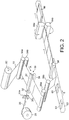
- Figure 2 of the drawings shows the general arrangement of a horizontally-operating form-fill-seal packaging machine which includes the apparatus of figure 1 which is indicated by the reference numeral 50.
- the apparatus 50 is orientated with the applicator bar 22 uppermost in figure 2 : any orientation is possible.
- a suitable vacuum device (not shown) is included to retain zipper lengths in the groove 24.
- the film 10 is stored in a roll 52 which can rotate to allow the film to be drawn by a pair of feed rollers 54a, 54b through the apparatus 50, whence it passes around further guide rollers 56a, 56b before being fed to a forming box 58 of a conventional horizontal form-fill-seal packaging machine.
- Articles 60 to be packaged are fed in the direction E shown by an arrow on a conveyor belt 62 to the forming box 58, where, in the conventional manner, the film 10 is folded around the article 60 and the longitudinal edges of the film 10 are brought together and sealed to each other to form a back seal.
- the folded film passes between a pair of heated cross-seal jaws 64a, 64b which form transverse seals between the inner faces of the folded film and also sever the film to provide individual sealed packages 64 containing the articles 60.
- the zipper 26 is cut into lengths which are slightly less than one-half of the width of the film 10, the male and female profiles of the zipper lengths being engaged with each other.
- the lengths of zipper are located by the applicator bar 22 centrally of the film 12.
- the length of zipper is attached to what becomes the other face of the package, so that, by the operation of the cross-seal jaws, heat is applied to the first face of the package to seal the zipper strip to that face and, after that, the film is severed into individual packages.
- the packages thus have a transverse heat seal at each end and, positioned inwardly of one of the seals, an openable and reclosable seal formed by the zipper strips for use after opening of the package by breaking the adjacent heat seal.
- Figure 3 of the drawings shows the operation of apparatus of figure 1 .
- the film 10 is shown moving in the direction A.
- the applicator bar 22 is shown movable between its first and second limit positions X, Y, determined by the linear motor 12. Movement from X to Y is referred to herein on the "forward stroke”; movement in the reverse direction is referred to on the "return stroke”.
- the lengths of zipper 26 are presented to the applicator bar 22 when it is in its first limit position X.
- the bar is then raised by the pneumatic cylinder 18 in the direction C until it contacts the lower surface of the film 12. Further movement in the direction C results in movement of the film 10 against the sealing bar to apply sealing heat to the opposite face of the film 12, the lower edge of the sealing bar coming to rest on the upper (as shown in figure 1 ) edge of the applicator bar 22 adjacent the groove 24.
- the applicator bar 22 and seal bar 32 are then moved in the direction B by the linear motor, until the second limit position Y is reached. During this movement, the speed of travel of the motor 14 and of the film 10 are equal to each other. At the second limit position Y, the applicator bar 22 is moved away from the film 10 in the direction C', leaving the zipper length 26 attached to the film 10, prior to its being returned to the first limit position X by movement in the direction B' by the linear motor 14. The cycle is then repeated to apply the zipper strips at spaced intervals along the length of the film 10.
- the motor 14 is capable of producing a very rapid acceleration and deceleration of the applicator bar 22 and the sealing bar 34, these taking place during the time taken for the movements in the directions C and C'.
- Figure 4 of the drawings is a schematic plan view corresponding to figure 3 and showing the assembly of the support platform 16, applicator bar 22, sealing bar 24, blade 32 and drive rollers 30a, 30b (all referred to collectively hereinafter as “the applicator unit") moving between the limit positions X and Y. It will be noted that, during this movement, the spool 28 containing the supply of zipper remains stationary whilst the zipper 26 feeding from the spool 18 can swing in an arc with the movement of the linear motor 14.
- FIGS 5a to 5e of the drawings show the operation of the apparatus of figure 4 in more detail.
- the film 10 is again shown moving continuously in the direction A.
- the applicator bar 22 is shown movable between its first and second limit positions X, Y, determined by the linear motor 12.
- Figure 5a shows an arbitrary starting point in the cycle in which the applicator bar 22 and the sealing bar 34 are at the first limit position X and with a length of zipper 26 received in the groove in the applicator bar. From this position, the applicator bar 22 is raised by the pneumatic cylinder 18 in the direction C until it contacts the lower surface of the film 12. Further movement in the direction C results in movement of the film 10 against the sealing bar 34 to apply sealing heat and pressure to the opposite face of the film 12, the lower edge 36 of the sealing bar coming to rest on the upper edge of the applicator bar 22 adjacent the groove 24. The condition shown in figure 5b of the drawings is thereby achieved. The application of heat from the sealing bar 32 to the applicator bar 22 adjacent the groove 24 causes fusion of the zipper strip to the film 10.
- the applicator unit is moved towards the second limit position Y by the linear motor in the direction B, the motor moving at the same linear speed as the film 10.
- the pneumatic cylinder 18 is actuated to lower the applicator bar 22 to leave the zipper length 26 adhered to the lower surface of the film 10.
- the groove in the applicator bar is now empty and ready to receive a further length of zipper supplied by the rollers 30a, 30b. This condition is shown in figure 5c . The condition may be reached at any point in the forward stroke of movement of the applicator unit from the first to the second limit position, up to the second limit position itself.
- a further length of zipper 26 is fed by the drive rollers 30a, 30b into the groove 24 in the applicator bar 22 and cut to length by the blade 32. This may take place before the applicator unit has reached the second limit position, at the second limit position, or at a later stage in the cycle of operation (see below).
- the condition achieved when the zipper length has been fed into the groove 24 not later than the second limit position is shown in figure 5d of the drawings.
- the applicator unit is brought to a halt by the linear motor 14. At this point in the operational cycle, a further length of zipper 26' may or may not have been fed into the applicator bar groove 24.
Landscapes
- Engineering & Computer Science (AREA)
- Mechanical Engineering (AREA)
- Making Paper Articles (AREA)
- Containers And Plastic Fillers For Packaging (AREA)
Applications Claiming Priority (2)
| Application Number | Priority Date | Filing Date | Title |
|---|---|---|---|
| GBGB0401500.4A GB0401500D0 (en) | 2004-01-23 | 2004-01-23 | Application of zippers to film material |
| PCT/GB2005/000216 WO2005070661A1 (en) | 2004-01-23 | 2005-01-21 | Application of zippers to a moving film material |
Publications (2)
| Publication Number | Publication Date |
|---|---|
| EP1711337A1 EP1711337A1 (en) | 2006-10-18 |
| EP1711337B1 true EP1711337B1 (en) | 2016-12-21 |
Family
ID=31971347
Family Applications (1)
| Application Number | Title | Priority Date | Filing Date |
|---|---|---|---|
| EP05701979.6A Ceased EP1711337B1 (en) | 2004-01-23 | 2005-01-21 | Application of zippers to a moving film material |
Country Status (7)
| Country | Link |
|---|---|
| US (1) | US7455636B2 (https=) |
| EP (1) | EP1711337B1 (https=) |
| JP (1) | JP4763619B2 (https=) |
| AU (1) | AU2005205963B2 (https=) |
| CA (1) | CA2554175C (https=) |
| GB (1) | GB0401500D0 (https=) |
| WO (1) | WO2005070661A1 (https=) |
Families Citing this family (22)
| Publication number | Priority date | Publication date | Assignee | Title |
|---|---|---|---|---|
| GB0419218D0 (en) | 2004-08-28 | 2004-09-29 | Supreme Plastics Holdings Ltd | Reclosable bag and zipper therefor |
| AU2008279501A1 (en) * | 2007-07-24 | 2009-01-29 | The Glad Products Company | Storage bag |
| US7681732B2 (en) | 2008-01-11 | 2010-03-23 | Cryovac, Inc. | Laminated lidstock |
| US20090257686A1 (en) * | 2008-04-14 | 2009-10-15 | Illinois Tool Works Inc. | Flow-wrapper package with reclosure |
| US20090317151A1 (en) * | 2008-06-24 | 2009-12-24 | Water-Line Sa | Feeding and fixing apparatus for feeding and fixing a functional element to a sheet of film |
| JP5633038B2 (ja) * | 2008-10-24 | 2014-12-03 | 中村 憲司 | シート類包装体ヒートシール装置 |
| WO2010092404A1 (en) | 2009-02-16 | 2010-08-19 | Illinois Tool Works Inc. | Zipper fasteners, sliders therefor, methods and apparatus for applying zipper fasteners to substrates |
| US20110207589A1 (en) * | 2010-02-24 | 2011-08-25 | Cmd Corporation | Pouch Machine With Sealer |
| US9061783B2 (en) * | 2010-04-29 | 2015-06-23 | Illinois Tool Works Inc. | Fin seal registration in manufacture of reclosable packages |
| US20150298864A1 (en) * | 2010-07-28 | 2015-10-22 | Illinois Tool Works Inc. | Unisex zippered packages with wide mouth and other features |
| ITBO20120021A1 (it) * | 2012-01-19 | 2013-07-20 | Marchesini Group Spa | Apparato per il prelievo di un astuccio tubolare in configurazione appiattita da un magazzino, per la messa a volume dell'astuccio tubolare e per il trasferimento dell'astuccio tubolare verso una stazione di ricevimento dell'astuccio tubolare |
| ITRM20130097A1 (it) * | 2013-02-20 | 2014-08-21 | Bosshart & Neupack Emballagen Bne Ag | Processo per applicare una chiusura a profili complementari ad una pellicola sottile, macchina per applicarla e nuova chiusura a profili complementari. |
| JP5682018B2 (ja) * | 2014-05-16 | 2015-03-11 | 中村 憲司 | 蓋付き包装体製造装置 |
| CN104070706B (zh) * | 2014-07-18 | 2016-08-17 | 江阴市汇通包装机械有限公司 | 拉链包装袋拉链封烫装置 |
| US10279944B2 (en) * | 2015-03-25 | 2019-05-07 | ProAmpac Intermediate, Inc. | Applicator systems for mounting strip-like fitments to flexible packaging |
| CN105015033B (zh) * | 2015-07-27 | 2017-09-12 | 依工功能塑料(上海)有限公司 | 拉链焊接机 |
| EP4269259A3 (en) | 2016-05-02 | 2024-03-06 | Kellogg Company | System and method for applying a fastening material to a substrate |
| CN106739164A (zh) * | 2016-12-28 | 2017-05-31 | 宁波斯凯勒智能科技有限公司 | 包装袋及加工该包装袋的机器人 |
| CN106696358B (zh) * | 2016-12-28 | 2019-06-18 | 宁波斯凯勒智能科技有限公司 | 一种用于加工包装袋的机器人 |
| CN110856897A (zh) * | 2018-08-22 | 2020-03-03 | 东莞市新力邦机械有限公司 | 一种封口袋的拉链头自动组装装置 |
| US11760582B2 (en) * | 2020-11-03 | 2023-09-19 | Ulma Packaging, S. Coop. | Product packaging installation |
| JP2023157728A (ja) * | 2022-04-15 | 2023-10-26 | 出光ユニテック株式会社 | フィルム片の接合装置、フィルムの製造装置、袋状容器の製造装置、フィルム片の接合方法、フィルムの製造方法および袋状容器の製造方法 |
Family Cites Families (21)
| Publication number | Priority date | Publication date | Assignee | Title |
|---|---|---|---|---|
| DE1215571B (de) * | 1962-05-10 | 1966-04-28 | Molins Organisation Ltd | Vorrichtung zum Abschneiden und Aufkleben eines Aufreissstreifens |
| US3692608A (en) * | 1971-01-20 | 1972-09-19 | Nasco Ind Inc | Sealing means and method |
| US4617683A (en) * | 1984-01-30 | 1986-10-14 | Minigrip, Inc. | Reclosable bag, material, and method of and means for making same |
| US4655862A (en) * | 1984-01-30 | 1987-04-07 | Minigrip, Incorporated | Method of and means for making reclosable bags and method therefor |
| US4878987A (en) * | 1987-03-16 | 1989-11-07 | Minigrip, Inc. | Transverse zipper bag material and method of and means for making same |
| DE3715146A1 (de) | 1987-05-07 | 1988-12-01 | Icoma Packtechnik Gmbh | Vorrichtung zur anbringung von schweissstellen, zum schneiden, perforieren und/oder beleimen von bahnfoermigem verpackungsmaterial |
| US4979933A (en) * | 1988-04-27 | 1990-12-25 | Kraft, Inc. | Reclosable bag |
| US6044621A (en) * | 1996-05-21 | 2000-04-04 | Illinois Tool Works Inc. | Zipper strip and method of positioning the strip transverse longitudinal axis |
| EP0928244B9 (en) * | 1996-07-24 | 2007-08-08 | Illinois Tool Works Inc. | Bag utilizing fastener tape material and method of manufacture thereof |
| JPH10296884A (ja) * | 1997-04-24 | 1998-11-10 | Illinois Tool Works Inc <Itw> | ジッパーストリップおよび長手の軸線に対して横断方向に前記ストリップを配設する方法 |
| US6350057B1 (en) * | 1997-05-22 | 2002-02-26 | Sealstrip Corp. | Reinforced reclosable package seals |
| US5944425A (en) * | 1997-05-22 | 1999-08-31 | Forman; Harold M | Packages with unitarilly formed resealable closure |
| DE29808817U1 (de) * | 1998-05-15 | 1999-09-23 | Robert Bosch Gmbh, 70469 Stuttgart | Vorrichtung zum Herstellen von wiederverschließbaren Schlauchbeutelpackungen |
| DE19829111C2 (de) * | 1998-06-30 | 2001-06-07 | Icoma Fbs Gmbh Packtechnik | Vorrichtung zum Bearbeiten von kontinuierlich gefördertem Verpackungsmaterial |
| GB9922747D0 (en) | 1999-09-24 | 1999-11-24 | Molins Plc | Method and apparatus for producing bags having a reclosable fastener |
| US6863754B2 (en) * | 1999-10-12 | 2005-03-08 | Com-Pac International, Inc. | Apparatus and method for manufacturing reclosable bags utilizing zipper tape material |
| US6588176B1 (en) * | 1999-12-17 | 2003-07-08 | Reynolds Consumer Products, Inc. | Methods of manufacturing reclosable packages using transverse closure and slider applicator |
| US6553740B2 (en) * | 2001-06-20 | 2003-04-29 | Illinois Tool Works Inc. | Transverse direction zipper applicator and method |
| US6732898B2 (en) * | 2001-10-30 | 2004-05-11 | Illinois Tool Works Inc. | Method and apparatus for feeding slider-zipper assemblies |
| GB0211573D0 (en) * | 2002-05-21 | 2002-06-26 | Supreme Plastics Holdings Ltd | Application of zippers to film material |
| US6751932B1 (en) * | 2003-02-19 | 2004-06-22 | Illinois Tool Works Inc. | Method for attaching reclosable zipper strip transversely to a sheet of thermoplastic film material |
-
2004
- 2004-01-23 GB GBGB0401500.4A patent/GB0401500D0/en not_active Ceased
-
2005
- 2005-01-21 CA CA2554175A patent/CA2554175C/en not_active Expired - Lifetime
- 2005-01-21 US US10/586,903 patent/US7455636B2/en not_active Expired - Lifetime
- 2005-01-21 WO PCT/GB2005/000216 patent/WO2005070661A1/en not_active Ceased
- 2005-01-21 JP JP2006550282A patent/JP4763619B2/ja not_active Expired - Fee Related
- 2005-01-21 AU AU2005205963A patent/AU2005205963B2/en not_active Ceased
- 2005-01-21 EP EP05701979.6A patent/EP1711337B1/en not_active Ceased
Non-Patent Citations (1)
| Title |
|---|
| None * |
Also Published As
| Publication number | Publication date |
|---|---|
| AU2005205963B2 (en) | 2008-12-11 |
| AU2005205963A1 (en) | 2005-08-04 |
| US7455636B2 (en) | 2008-11-25 |
| WO2005070661A1 (en) | 2005-08-04 |
| CA2554175C (en) | 2010-05-11 |
| US20070283664A1 (en) | 2007-12-13 |
| GB0401500D0 (en) | 2004-02-25 |
| EP1711337A1 (en) | 2006-10-18 |
| JP2007518606A (ja) | 2007-07-12 |
| JP4763619B2 (ja) | 2011-08-31 |
| CA2554175A1 (en) | 2005-08-04 |
Similar Documents
| Publication | Publication Date | Title |
|---|---|---|
| EP1711337B1 (en) | Application of zippers to a moving film material | |
| EP0453522B1 (en) | Form, fill, seal and separate packaging machine for reclosable containers | |
| US4858416A (en) | Tensionless seal apparatus and method | |
| US3599388A (en) | Method of and apparatus for forming and loading containers | |
| US8539741B2 (en) | Seal and cut method and apparatus | |
| US5519982A (en) | Pouch having easy opening and reclosing characteristics and method and apparatus for production thereof | |
| EP0608123A1 (en) | Pouch having easy opening and reclosing characteristics and method and apparatus for production thereof | |
| US6810641B2 (en) | Method and apparatus for forming double zipper bags | |
| JPH05262335A (ja) | パッケージフィルムに閉鎖手段を整列装着する方法及び装置 | |
| CA2400018A1 (en) | Apparatus for manufacturing flexible packages having slide closures | |
| EP3154867A1 (en) | Easy open and reclosable gusseted package with die-cut web and reclosure mechanism | |
| US10926905B2 (en) | Vertical form, fill and seal machine with ultrasonic vertical seal and reclosable fastener attachment | |
| JP2003146303A (ja) | スライダを有するジッパーを使用した形成・充填・シール梱包方法 | |
| EP2308758A1 (en) | Method and apparatus for manufacturing and filling flexible containers as well as the container obtained | |
| EP0100609B1 (en) | Apparatus and method for forming and stacking plastic bags | |
| EP1459986A1 (en) | Method and apparatus for zipper strip attachment | |
| US7114309B2 (en) | Method and apparatus for making reclosable packages having slider-actuated string zippers | |
| US6656297B2 (en) | Method for applying a narrow web zipper transverse to the film direction | |
| US4800705A (en) | Continuous form, fill, seal and separate packaging machine | |
| US20040104526A1 (en) | Method and device for the packaging of flat objects | |
| CN114531867B (zh) | 改进的密封装置 | |
| CA2059354A1 (en) | In-line bread bag forming and sealing machine |
Legal Events
| Date | Code | Title | Description |
|---|---|---|---|
| PUAI | Public reference made under article 153(3) epc to a published international application that has entered the european phase |
Free format text: ORIGINAL CODE: 0009012 |
|
| 17P | Request for examination filed |
Effective date: 20060721 |
|
| AK | Designated contracting states |
Kind code of ref document: A1 Designated state(s): DE FR GB IT PL |
|
| RAP1 | Party data changed (applicant data changed or rights of an application transferred) |
Owner name: ILLINOIS TOOL WORKS INC. |
|
| DAX | Request for extension of the european patent (deleted) | ||
| RBV | Designated contracting states (corrected) |
Designated state(s): DE FR GB IT PL |
|
| RAP1 | Party data changed (applicant data changed or rights of an application transferred) |
Owner name: ILLINOIS TOOL WORKS INC. |
|
| 17Q | First examination report despatched |
Effective date: 20160223 |
|
| GRAP | Despatch of communication of intention to grant a patent |
Free format text: ORIGINAL CODE: EPIDOSNIGR1 |
|
| INTG | Intention to grant announced |
Effective date: 20160913 |
|
| STAA | Information on the status of an ep patent application or granted ep patent |
Free format text: STATUS: GRANT OF PATENT IS INTENDED |
|
| GRAS | Grant fee paid |
Free format text: ORIGINAL CODE: EPIDOSNIGR3 |
|
| GRAA | (expected) grant |
Free format text: ORIGINAL CODE: 0009210 |
|
| STAA | Information on the status of an ep patent application or granted ep patent |
Free format text: STATUS: THE PATENT HAS BEEN GRANTED |
|
| AK | Designated contracting states |
Kind code of ref document: B1 Designated state(s): DE FR GB IT PL |
|
| REG | Reference to a national code |
Ref country code: GB Ref legal event code: FG4D |
|
| REG | Reference to a national code |
Ref country code: DE Ref legal event code: R096 Ref document number: 602005050945 Country of ref document: DE |
|
| REG | Reference to a national code |
Ref country code: FR Ref legal event code: PLFP Year of fee payment: 13 |
|
| PG25 | Lapsed in a contracting state [announced via postgrant information from national office to epo] |
Ref country code: PL Free format text: LAPSE BECAUSE OF FAILURE TO SUBMIT A TRANSLATION OF THE DESCRIPTION OR TO PAY THE FEE WITHIN THE PRESCRIBED TIME-LIMIT Effective date: 20161221 |
|
| REG | Reference to a national code |
Ref country code: DE Ref legal event code: R097 Ref document number: 602005050945 Country of ref document: DE |
|
| PLBE | No opposition filed within time limit |
Free format text: ORIGINAL CODE: 0009261 |
|
| STAA | Information on the status of an ep patent application or granted ep patent |
Free format text: STATUS: NO OPPOSITION FILED WITHIN TIME LIMIT |
|
| 26N | No opposition filed |
Effective date: 20170922 |
|
| REG | Reference to a national code |
Ref country code: FR Ref legal event code: PLFP Year of fee payment: 14 |
|
| PGFP | Annual fee paid to national office [announced via postgrant information from national office to epo] |
Ref country code: IT Payment date: 20220119 Year of fee payment: 18 |
|
| PGFP | Annual fee paid to national office [announced via postgrant information from national office to epo] |
Ref country code: FR Payment date: 20230125 Year of fee payment: 19 |
|
| PGFP | Annual fee paid to national office [announced via postgrant information from national office to epo] |
Ref country code: GB Payment date: 20230127 Year of fee payment: 19 Ref country code: DE Payment date: 20230127 Year of fee payment: 19 |
|
| P01 | Opt-out of the competence of the unified patent court (upc) registered |
Effective date: 20230606 |
|
| PG25 | Lapsed in a contracting state [announced via postgrant information from national office to epo] |
Ref country code: IT Free format text: LAPSE BECAUSE OF NON-PAYMENT OF DUE FEES Effective date: 20230121 |
|
| REG | Reference to a national code |
Ref country code: DE Ref legal event code: R119 Ref document number: 602005050945 Country of ref document: DE |
|
| GBPC | Gb: european patent ceased through non-payment of renewal fee |
Effective date: 20240121 |
|
| PG25 | Lapsed in a contracting state [announced via postgrant information from national office to epo] |
Ref country code: DE Free format text: LAPSE BECAUSE OF NON-PAYMENT OF DUE FEES Effective date: 20240801 |
|
| PG25 | Lapsed in a contracting state [announced via postgrant information from national office to epo] |
Ref country code: GB Free format text: LAPSE BECAUSE OF NON-PAYMENT OF DUE FEES Effective date: 20240121 |
|
| PG25 | Lapsed in a contracting state [announced via postgrant information from national office to epo] |
Ref country code: FR Free format text: LAPSE BECAUSE OF NON-PAYMENT OF DUE FEES Effective date: 20240131 |
|
| PG25 | Lapsed in a contracting state [announced via postgrant information from national office to epo] |
Ref country code: GB Free format text: LAPSE BECAUSE OF NON-PAYMENT OF DUE FEES Effective date: 20240121 Ref country code: FR Free format text: LAPSE BECAUSE OF NON-PAYMENT OF DUE FEES Effective date: 20240131 Ref country code: DE Free format text: LAPSE BECAUSE OF NON-PAYMENT OF DUE FEES Effective date: 20240801 |