EP1711270B1 - Distributeur de fluides - Google Patents
Distributeur de fluides Download PDFInfo
- Publication number
- EP1711270B1 EP1711270B1 EP05702129A EP05702129A EP1711270B1 EP 1711270 B1 EP1711270 B1 EP 1711270B1 EP 05702129 A EP05702129 A EP 05702129A EP 05702129 A EP05702129 A EP 05702129A EP 1711270 B1 EP1711270 B1 EP 1711270B1
- Authority
- EP
- European Patent Office
- Prior art keywords
- dispenser
- metering chamber
- section
- chamber
- fluid product
- Prior art date
- Legal status (The legal status is an assumption and is not a legal conclusion. Google has not performed a legal analysis and makes no representation as to the accuracy of the status listed.)
- Active
Links
Images


Classifications
-
- B—PERFORMING OPERATIONS; TRANSPORTING
- B05—SPRAYING OR ATOMISING IN GENERAL; APPLYING FLUENT MATERIALS TO SURFACES, IN GENERAL
- B05B—SPRAYING APPARATUS; ATOMISING APPARATUS; NOZZLES
- B05B11/00—Single-unit hand-held apparatus in which flow of contents is produced by the muscular force of the operator at the moment of use
- B05B11/01—Single-unit hand-held apparatus in which flow of contents is produced by the muscular force of the operator at the moment of use characterised by the means producing the flow
- B05B11/10—Pump arrangements for transferring the contents from the container to a pump chamber by a sucking effect and forcing the contents out through the dispensing nozzle
- B05B11/1001—Piston pumps
- B05B11/1009—Piston pumps actuated by a lever
- B05B11/1011—Piston pumps actuated by a lever without substantial movement of the nozzle in the direction of the pressure stroke
-
- B—PERFORMING OPERATIONS; TRANSPORTING
- B05—SPRAYING OR ATOMISING IN GENERAL; APPLYING FLUENT MATERIALS TO SURFACES, IN GENERAL
- B05B—SPRAYING APPARATUS; ATOMISING APPARATUS; NOZZLES
- B05B11/00—Single-unit hand-held apparatus in which flow of contents is produced by the muscular force of the operator at the moment of use
- B05B11/01—Single-unit hand-held apparatus in which flow of contents is produced by the muscular force of the operator at the moment of use characterised by the means producing the flow
- B05B11/10—Pump arrangements for transferring the contents from the container to a pump chamber by a sucking effect and forcing the contents out through the dispensing nozzle
- B05B11/1001—Piston pumps
- B05B11/1004—Piston pumps comprising a movable cylinder and a stationary piston
-
- B—PERFORMING OPERATIONS; TRANSPORTING
- B05—SPRAYING OR ATOMISING IN GENERAL; APPLYING FLUENT MATERIALS TO SURFACES, IN GENERAL
- B05B—SPRAYING APPARATUS; ATOMISING APPARATUS; NOZZLES
- B05B11/00—Single-unit hand-held apparatus in which flow of contents is produced by the muscular force of the operator at the moment of use
- B05B11/01—Single-unit hand-held apparatus in which flow of contents is produced by the muscular force of the operator at the moment of use characterised by the means producing the flow
- B05B11/10—Pump arrangements for transferring the contents from the container to a pump chamber by a sucking effect and forcing the contents out through the dispensing nozzle
- B05B11/109—Pump arrangements for transferring the contents from the container to a pump chamber by a sucking effect and forcing the contents out through the dispensing nozzle the dispensing stroke being affected by the stored energy of a spring
- B05B11/1092—Pump arrangements for transferring the contents from the container to a pump chamber by a sucking effect and forcing the contents out through the dispensing nozzle the dispensing stroke being affected by the stored energy of a spring automatically released from a loaded state at the end of the loading stroke
-
- B—PERFORMING OPERATIONS; TRANSPORTING
- B05—SPRAYING OR ATOMISING IN GENERAL; APPLYING FLUENT MATERIALS TO SURFACES, IN GENERAL
- B05B—SPRAYING APPARATUS; ATOMISING APPARATUS; NOZZLES
- B05B11/00—Single-unit hand-held apparatus in which flow of contents is produced by the muscular force of the operator at the moment of use
- B05B11/01—Single-unit hand-held apparatus in which flow of contents is produced by the muscular force of the operator at the moment of use characterised by the means producing the flow
- B05B11/02—Membranes or pistons acting on the contents inside the container, e.g. follower pistons
- B05B11/028—Pistons separating the content remaining in the container from the atmospheric air to compensate underpressure inside the container
Definitions
- the present invention relates to a dispenser for dispensing a metered volume of a fluid product and is particularly, but not exclusively, concerned with a dispenser for dispensing a metered volume of a fluid medicament, for instance medicaments having liquid, gaseous, powder or topical (cream, paste etc.) formulations.
- the invention also has application in the area of consumer healthcare, as in the case of toothpaste, sun cream lotion etc.
- Fluid product dispenser having metering mechanisms are known in the art.
- MDI metered dose inhalers
- the fluid product is contained under pressure in a canister having an open end closed off by a valve mechanism.
- the valve mechanism has a valve body which defines a fixed volume metering chamber through which a valve stem is sealingly slidable between filling and discharging positions.
- the valve stem places the metering chamber in fluid communication with the canister contents, but isolates the metering chamber from the external environment.
- the valve stem is moved to the discharge position, the metering chamber is placed in fluid communication with the external environment, but isolated from the canister contents. In this way, a metered volume of fluid product is sequentially transferred to the metering chamber and then discharged to the external environment for inhalation by a patient.
- FR-A-2 692040 discloses a product dispenser having a chamber which is movable between a first position, in which product in a reservoir transfers into the chamber, and a second position, in which the product in the chamber is able to be dispensed through an outlet. On moving to the second position, the chamber volume contracts to push the product through the outlet.
- WO-A-90/07351 discloses a reservoir powder inhaler in which a piston pump arrangement is used to entrain powder from a metering chamber towards a mouthpiece.
- the present invention provides a dispenser for a fluid product having a novel dispensing mechanism.
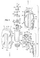
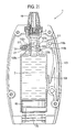
- FIGURES 1 to 3 show a fluid dispenser 1 in accordance with the present invention whose underlying principle of operation is as described and claimed in International patent application Nos. WO-A-2004014566 and WO-A-2004014567 .
- the fluid dispenser 1 has an outer casing 3 comprising first and second outer casing halves 5a, 5b.
- the outer casing 3 is assembled through the interengagement of complementary male and female connectors 7a, 7b formed on the inner surfaces 9a, 9b of the outer casing halves 5a, 5b.
- the male connectors 7a are pegs and the female connectors 7b are apertures into which the pegs are slidably receivable.
- the outer casing 3 is preferably made from a plastics material, for instance by moulding. Most preferably, the outer casing is made from acrylonitrile-butadiene-styrene (ABS).
- ABS acrylonitrile-butadiene-styrene
- the outer casing 3 of the fluid dispenser 1 is held in the hand H of a human user when operating the fluid dispenser 1.
- the user's hand H which holds the outer casing 3 is also able to be used to actuate the fluid dispenser 1, as will be understood further hereinafter.
- the outer casing halves 5a, 5b have a shell-like form whereby when assembled they enclose an internal chamber 11.
- an upper end 13 of the outer casing 3 there is a passageway 15 to the internal chamber 11 bounded by concave recesses 17a, 17b in the outer casing halves 5a, 5b.
- the passageway 15 is coaxially arranged with a longitudinal axis X-X of the fluid dispenser 1 and has a generally circular lateral cross section.
- the passageway 15 receives a nozzle 19 of the fluid dispenser 1, which in this embodiment is shaped and sized for insertion into a nostril of a human user (i.e. a nasal nozzle).
- the fluid dispenser 1 is an intra-nasal fluid dispenser.
- the nasal nozzle 19 in this particular embodiment has an outer surface 20 which has a generally circular lateral cross section and which curves laterally inwardly in the upward direction denoted by arrow U.
- the nasal nozzle 19 is preferably made from a plastics material, for instance from polypropylene (PP), and may, for example, be formed by moulding.
- PP polypropylene
- the nasal nozzle 19 is axially aligned with the longitudinal axis X-X and has a longitudinal bore 21 to direct the liquid dispensed from the dispenser 1 in the upward direction U along the longitudinal axis X-X.
- the nasal nozzle 19 has a generally cylindrical, open-ended inner tubular section 23 whose inner circumferential surface 25 defines the nozzle bore 21.
- the tubular section 23 provides an upper opening 27 of the nozzle bore 21 which is the outlet orifice of the fluid dispenser 1.
- the nasal nozzle 19 can be of other shapes and configurations suited for insertion into a human nostril.
- a generally cylindrical valve body 28 of a one-way (non-return), poppet-type outlet valve 30 is fixedly, sealingly secured on an outer circumferential surface 29 of the nozzle inner tubular section 23 at its lower end 31 so that a lateral lower end wall 34 of the generally U-shaped valve body 28 is disposed underneath a lower opening 32 of the nozzle bore 21.
- the lateral lower end wall 34 of the valve body 28 includes a valve opening 33 and an outlet valve control member 35 operates in use to selectively place the outlet valve opening 33 and the nozzle bore 21 in flow communication so that a metered volume (metered dose) of the liquid 2 is able to flow through the outlet valve 30 into the nozzle bore 21, as will be described in more detail hereinafter.
- the outlet valve control member 35 has a generally cylindrical, tubular stem which is open at its upper end and closed by a flange plate at its lower end. One or more apertures 40 are provided in the tubular stem.
- the tubular stem is sealingly, slidably mounted in the lower opening 32 of the nozzle bore 21.
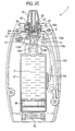
- the outlet valve control member 35 is biased by an outlet valve return spring 38, preferably integrally formed with the outlet valve control member 35, to a rest position in which the flange plate of the outlet valve control member 35 sealingly closes the valve opening 33 by seating on a valve seat 36, as shown in FIGURE 2A .
- the outlet valve control member 35 is lifted off the valve seat 36 to place the valve opening 33 in flow communication with the nozzle bore 21 through the one or more apertures 40 in the tubular stem of the outlet valve control member 35, as will be described in more detail hereinafter, particularly with reference to FIGURE 3 .
- the components 28,35 of the metering valve 30 may be made from polypropylene (PP), for example by moulding.
- the valve body 28 has an outer circumferential surface 37 on which is provided upper and lower sealing rings 39, 41.
- the upper and lower sealing rings 39, 41 may be integrally formed with the valve body 28 or be separate valve components.
- a generally U-shaped sliding member 43 is sealingly, slidably mounted on the outer circumferential surface 37 of the U-shaped valve body 28 for reciprocation along the longitudinal axis X-X between upper and lower positions relative to the U-shaped valve body 28. More particularly, the U-shaped sliding member 43 has a generally circular, longitudinal side wall 45 having an inner circumferential surface 47 which sealingly slides over the upper and lower sealing rings 39, 41 on the valve body 28. The U-shaped sliding member 43 further has a lateral lower end wall 49 which, in the upper position, abuts with the lateral lower end wall 34 of the valve body 28 (see e.g.
- FIGURES 2A , 2B and 2F to 2I which, in the lower position ( FIGURES 2D and 2E ), is spaced downwardly from the lateral lower end wall 34 of the valve body 28. It can therefore be seen that the U-shaped valve body 28 and the U-shaped sliding member 43 are arranged in a nesting configuration.
- the longitudinal side wall 45 of the U-shaped sliding member 43 has an outwardly extending connector flange 51 at an intermediate position of its outer circumferential surface 53.
- four equiangularly spaced transfer ports 55a, 55b extend laterally through the longitudinal side wall 45 of the U-shaped sliding member 43 at a position below the connector flange 51.
- the number of transfer ports can be decreased or increased as desired.
- the U-shaped sliding member 43 is made from a plastics material, e.g. by moulding.
- a preferred plastics material is polypropylene (PP).
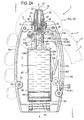
- a generally cylindrical, liquid-containing hollow container 57 is affixed to the U-shaped sliding member 43 so as to reciprocate therewith on the longitudinal axis X-X.
- the container 57 has an open-ended container body 56 having a generally U-shaped head 59 at an upper end 61 which nests with the U-shaped sliding member 43 to be fixedly, sealingly engaged with the connector flange 51 of the U-shaped sliding member 43, e.g. by adherence therebetween.
- connection is such that the lower section 60 of the outer circumferential surface 53 of the U-shaped sliding member 43, which is below the connector flange 51, is spaced laterally inwardly of the inner circumferential surface 62 of the U-shaped container head 59 so as to form an annular channel 64 therebetween, which is sealingly closed off at the upper end 61 by the connector flange 51 and into which the transfer ports 55a, 55b open.
- the container body 56 further has an enlarged hollow base 63 at a lower end 65 and a hollow neck 67 which extends longitudinally from the base 63 to the head 59.
- a sealing piston 69 is sealingly, slidably mounted in the container body base 63 to sealingly close the container body 56 at the lower end 65.
- the container body 56 is made from glass, although, of course, other inert materials may be used, for example a plastics material, such as polypropylene (PP). Where the container body 56 is made from a plastics material, it can be connected to the flange 51 of the plastics U-shaped sliding member 43 by welding, e.g. by ultrasonic welding.
- PP polypropylene
- the sealing piston 69 is made from a plastics material, e.g. by moulding, and is preferably made from butyl rubber.
- the container 57 contains a liquid medicament formulation.
- the lower end of the annular channel 64 about the U-shaped sliding member 43 is in flow communication with the inner volume of the container body neck 67 which in turn is in flow communication with the inner volume of the closed container body base 63.
- the container 57 co-operates with the sliding member 43 to define a container inner volume 71 which is only open at the transfer ports 55a, 55b due to the inner volume 71 being sealed by the sealing piston 69 at the lower end 65 and by the connector flange 51 at the upper end 61.
- the assembly of the U-shaped sliding member 43 and the container 57 will now be referred to as the "container unit 58".
- the U-shaped sliding member 43 and the lateral lower end wall 34 of the metering valve body 28 co-operate to define a pumping metering chamber 73 therebetween which is either sealed or selectively open to the transfer ports 55a, 55b or the nozzle bore 21 depending on the sliding position of the container unit 58 on the valve body 28, as will be detailed further hereinafter.
- the fluid dispenser 1 is filled with sufficient liquid 2 that, before it is first used, it completely fills the container inner volume 71, including the annular channel 64. Moreover, the fluid dispenser operation is such that the container inner volume 71 is kept airless, i.e. there is no headspace.
- a return spring 75 of compression type acts on the container base 63 to bias the container unit 58 in the upward direction U to an upper sliding position in the outer casing 3 in which the U-shaped sliding member 43 is disposed in its upper position on the valve body 28.
- the fluid dispenser 1 is adapted so that, in its rest or non-actuated state, the container unit 58 is placed in the upper sliding position by the return spring 75.
- the upper sliding position of the container unit 58 is defined by the abutment of the lateral lower end wall 49 of the U-shaped sliding member 43 with the lateral lower end wall 34 of the valve body 28 (i.e. when the U-shaped sliding member 43 is in its upper sliding position on the valve body 28).
- the pumping metering chamber 73 has no, or substantially no, volume in the rest state of the fluid dispenser 1.
- the transfer ports 55a, 55b are disposed in-between the upper and lower sealing rings 39, 41 on the valve body 28.
- the outlet valve control member 35 is in its closed position. Consequently, the metering chamber 73 is not in flow communication with the inner volume counter 71 of the container 57 nor with the nozzle bore 21. That is to say, the metering chamber 73 is sealed.
- the inner volume 71 of the container unit 58 is completely sealed in the rest state of the fluid dispenser 1 inasmuch as contaminants, such as air and moisture, cannot enter the container inner volume 71 at its lower end 65, due to the sealing piston 69, nor at the upper end 61 by virtue of the position of the transfer ports 55a, 55b between the sealing rings 39, 41, the collapsed state of the metering chamber 73 and the closed position of the outlet valve control member 35.
- the components of the fluid dispenser 1 are made from fluid impervious materials.
- the fluid dispenser 1 is provided with a hand-operable actuating mechanism 100 for reciprocating the container unit 58 along the longitudinal axis X-X to cause a metered dose of the liquid 2 to be dispensed.
- the actuating mechanism 100 drives the container unit 58 downwardly in the direction of arrow D against the return force of the return spring 75.
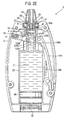
- the U-shaped sliding member 43 parts from the valve body 28 so as to increase the volume of the metering chamber 73, as shown in FIGURES 2C to 2E .
- the transfer ports 55a, 55b slide past the lower sealing ring 41 to place the metering chamber 73 and the container inner volume 71 in flow communication with one another. Liquid from the container 57 is then drawn into the metering chamber 73 due to the negative pressure created in the metering chamber 73 during the downward stroke of the container unit 58.
- the sealing piston 69 slides up in the container base 63, under the influence of the negative pressure, to decrease the inner volume 71 of the container 57 by an amount equivalent to the liquid volume transferred into the metering chamber 73. Accordingly, no headspace is generated over the liquid 2 in the container 57 during the filling of the metering chamber 73.
- outlet valve control member 35 remains closed in the downward stroke to prevent escape of any of the liquid 2 transferred into the metering chamber 73 during this filling mode of operation of the fluid dispenser 1.
- the sealing piston 69 moves downwardly to a new rest position which is spaced upwardly of its previous rest position before the filling mode of operation.
- the increase in the container inner volume 71 in the bleed mode is equivalent to the volume of liquid bled back thereinto. Thus, no headspace is created in the container inner volume 71 in the bleed mode.
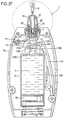
- the transfer ports 55a, 55b are juxtaposed with the lower sealing ring 41 so as to be closed thereby.
- the metering chamber 73 now defines the metering volume of the fluid dispenser 1 and is filled with a metered volume of the liquid 2 transferred thereinto during the filling mode of operation.
- the metering volume is 50 ⁇ L, although, of course, the fluid dispenser 1 can be made to produce other metering volumes depending on the specific application and/or product to be dispensed.
- the volume of the metering chamber 73 continues to reduce to increase the hydraulic pressure therein causing the outlet valve control member 35 to lift off the outlet valve seat 36 and the metered volume of liquid 2 to be pumped from the metering chamber 73 out of the dispenser outlet orifice 27 via the nozzle bore 21.
- This is the dispensing mode of operation of the fluid dispenser 1 and is shown schematically in FIGURE 3 .
- the outlet valve control member 35 re-closes the outlet valve opening 33.
- an actuation cycle of the fluid dispenser 1 results in the sealing piston 69 moving upwardly by an amount which results in the container inner volume 71 reducing by the metered volume. This ensures that no headspace is provided in the container inner volume 71 thereby ensuring no air is present therein. Accordingly, repeated use of the fluid dispenser 1 causes the sealing piston 69 to move incrementally upwardly until it bears against the roof 66 of the container base 63 whereupon no further dispensing takes place.
- the pumping force of the fluid dispenser 1 is such as to produce an atomised spray having a relative small and uniform droplet size ideal for delivery to the nasal passage of the user.
- the fluid dispenser 1 may be adapted to dispense the metered volume as a spray of droplets having a diameter in the range of 10-20 ⁇ m.
- each further actuation of the actuating mechanism 100 results in this cycle of events being repeated until the sealing piston 69 abuts the roof 66 of the container base 63.
- the inner volume 71 of the container base 63 which corresponds to the volume of liquid 2 that is dispensable from the fluid dispenser 1, is 14ml. Consequently, the fluid dispenser 1 has 280 actuations.
- the container 57 can be filled with the liquid 2 after it has been assembled into the fluid dispenser 1 by forming the sealing piston 69 so that it is able to be sealingly pierced by a needle-like object and then sealably reclose after withdrawal of the needle-like object (e.g. a "septum").
- the needle-like object e.g. a "septum”
- the liquid could be injected through the sealing piston 69.
- the outer casing halves 5a, 5b each have a base with a concave cut-out 81 a, 81 b which, when the outer casing 3 is assembled, provide an aperture in the outer casing base. The injector could be inserted through the sealing piston 69 via this aperture.
- the actuation mechanism is lever-based in the sense that actuation is effected through an actuation lever 101 which is mounted to the outer casing 3 in a longitudinal slot 102 thereof formed by the junction of opposed sides of the outer casing halves 5a, 5b.
- the actuation lever 101 has a lower end 103 which is pivotally connected to the outer casing 3 at a pivot point 105 for pivotal movement about a first lateral pivot axis P1-P1.
- the actuation lever 101 has an inner surface 107 from which depends a return leaf spring 108.
- the return leaf spring 108 which is preferably an integrally formed part of the lever 101, co-operates with the container base 63 to bias the actuation lever 101 to an outward rest position in which it forms a flush fit in the outer casing 3, as shown in FIGURE 2A , for example. This is the position the actuation lever 101 adopts in the non-actuated or rest state of the fluid dispenser 1.
- the user picks up the fluid dispenser 1 in their hand H and pushes the actuation lever 101 from its outward rest position into the outer casing 3 to cause it to pivot about the first pivot axis P1-P1 against the return force of the leaf spring 108.
- the user uses a digit of the hand H holding the fluid dispenser 1 to push the actuation lever 101 inwardly, in this instance their thumb T.
- the actuation lever 101 is returned to the outward return position upon release, or relaxation, of the pushing force F on the actuation lever 101 by the return spring 108.
- the user pushes the actuation lever 101 inwardly after the nozzle 19 has been inserted into one of their nostrils.
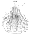
- a laterally extending drive structure 109 which is so constructed and arranged in the fluid dispenser 1 to transmit the inward pivotal motion of the actuation lever 101 into a downward driving force on the container unit 58 to effect the downward stroke thereof, as described hereinabove.
- the drive structure 109 has a generally U-shaped outer carrier frame 111 pivotally connected to the actuation lever 101 for pivotal movement about a second lateral pivot axis P2-P2 which extends generally parallel to the first pivot axis P1-P1.
- the U-shaped outer carrier frame 111 has a pair of generally parallel side members 113a, 113b which straddle the neck 67 of the container 57 on opposed sides thereof and are connected at first ends thereof to pivot points 115a, 115b on the actuation lever inner surface 107, and a crossbar member 117 which connects the side members 113a, 113b at second ends thereof.
- the U-shaped outer carrier frame 111 forms a hollow box-like structure with the actuation lever 101 which encloses the neck 67 of the container 57.
- the U-shaped outer carrier frame 111 further has a return leaf spring 119a, 119b depending from the first end of each side member 113a, 113b which co-operates with the inner surface 107 of the actuation lever 101 to bias the U-shaped carrier frame 111 to an upper pivot position which, for example, is shown in FIGURE 2A .
- the drive structure 109 further comprises a generally U-shaped inner cam frame 121 which is carried by the U-shaped outer carrier frame 111 on the inside thereof.
- the inner cam frame 121 has a pair of generally parallel side members 123a, 123b which are arranged generally parallel to the side members 113a, 113b of the outer carrier frame 111.
- the inner cam frame side members 123a, 123b are each provided with an outwardly projecting lug 125a, 125b at a first end thereof which is received in a longitudinal slide aperture 127a, 127b formed in the adjacent outer carrier frame side member 113a, 113b between the first and second ends thereof.
- the inner cam frame side members 123a, 123b are also each provided with an inwardly projecting cam element 129a, 129b of wing-like cross-section, the function of which will be outlined further hereinafter.
- the inner cam frame 121 further has a crossbar member 131 which connects the side members 123a, 123b at second ends thereof.
- the inner cam frame crossbar member 131 is configured as a C-shape clip which clips to the crossbar member 117 of the outer carrier frame 111 to enable the inner cam frame 121 to be pivotal thereabout.
- the pivotal movement of the inner cam frame 121 on the outer carrier frame 111 is governed by sliding movement of the lugs 125a, 125b in the associated slide apertures 127a, 127b.
- the end limits of the pivotal movement of the inner cam frame 121 about the crossbar member 117 of the outer carrier frame 111 between lower and upper pivot positions are respectively determined by the abutment of the lugs 125a, 125b with the lower and upper ends of the longitudinal slide apertures 127a, 127b.
- the inner cam frame 121 yet further comprises a return leaf spring 133a, 133b projecting upwardly from each opposing end of the crossbar member 131.
- the return leaf springs 133a, 133b of the inner cam frame 121 each co-operate with an abutment surface 134 on the adjacent outer carrier frame side member 113a, 113b to bias the inner cam frame 121 in the downward direction D to its lower pivot position.
- the lugs 125a, 125b of the inner cam frame 121 are held against the lower ends of the slide apertures 127a, 127b of the outer carrier frame 111.
- the function of the inner cam frame 121 is to convert the inward movement of the actuation lever 101 into a downward camming action on the container unit 58 and thereby place the fluid dispenser 1 in its filling mode.
- a pair of diametrically opposed peg-shaped cam followers 135a, 135b extend laterally from the neck 67 of the container 57.
- the cam followers 135a, 135b and cam elements 129a, 129b on the inner cam frame 121 co-operate to produce the downward stroke of the container unit 58 representing the filling mode, as will now be described in more detail.
- the component parts thereof adopt the relative positions shown in FIGURE 2A .
- the container unit 58 is held in its upper slide position by the return spring 75, the actuation lever 101 is in its outward pivot position, the outer carrier frame 111 is in its upper pivot position and the inner cam frame 121 is in its lower pivot position.
- the actuation lever 101 is pivoted inwardly, as discussed previously, and this pivotal inward movement is transmitted to the drive structure 109 causing it to be displaced laterally inwardly.
- the inner carrier frame 121 is moved from its lower pivot position relative to the outer carrier frame 111 to its upper pivot position as a result of the cam elements 129a, 129b riding up the upper surfaces of the cam followers 135a, 135b.
- the lugs 125a, 125b are caused to slide upwardly in the slide apertures 127a, 127b from the lower end of the slide apertures 127a, 127b to the upper ends with concomitant compression of the inner cam frame leaf springs 133a, 133b.
- the inner carrier frame 121 is "locked" in its upper pivot position.
- FIGURE 3 shows in detail how the outlet valve control member 35 is lifted off the outlet valve seat 36 during the dispensing mode by the hydraulic pressure built up in the metering chamber 73 once the metering chamber 73 is sealed after the bleed mode. As indicated by the arrows, this allows the liquid 2 to be pumped through the outlet valve aperture 33, around the side of the outlet valve control member 35, through the aperture(s) 40 in the outlet valve control member 35 and out of the outlet orifice 27 via the nozzle bore 21.
- the inward movement of the drive structure 109 is delimited by abutment of the crossbar 131 of the inner cam frame 121 with an inner surface of the outer casing 3.
- FIGURES 2G to 2I This sequence is shown in FIGURES 2G to 2I from which it will be noted that, in an initial phase of the concomitant returning outward movement of the drive structure 109, the cam elements 129a, 129b re-engage the cam followers 135a, 135b, albeit this time riding over the lower cam follower surfaces due to the lugs 125a, 125b now being at the lower ends of the slide apertures 127a, 127b. Moreover, for the same reason, the outer carrier frame 111 tilts to its lower pivot position on the actuation lever 101.
- the cam elements 129a, 129b Towards the end of the return movement of the actuation mechanism 100 to its rest state, the cam elements 129a, 129b disengage from the cam followers 135a, 135b thereby enabling the outer carrier frame 111 and inner cam frame 121 to return to their respective rest states.
- the actuation lever 101, the outer carrier frame 111 and the inner cam frame 121 are made from a plastics material, for instance ABS, as an example by moulding.
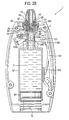
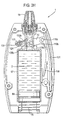
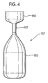
- the container 57 may be replaced by a bag structure which would contract and expand in equivalent fashion, and for equivalent function, as the container 57, e.g. by being made from a flexible material, for instance a plastics material.
- a bag structure over the container 57 would be that it avoids the need for a complex structure for contraction and expansion of its inner volume.
- FIGURE 4 An example of a bag container 157 is shown in FIGURE 4 with like reference numerals indicating like features in the container 57 of FIGURES 1 to 3 .
- the bag container 157 has a head 159 and a neck 167 corresponding to those in the container 57.
- the base 163 of the bag container 157 is formed by a bag element which expands/contracts depending on the mode of operation of the fluid dispenser 1.
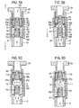
- FIGURES 5A to 5G there is shown an alternative valve arrangement for use in the fluid dispenser 1 of FIGURES 1 to 3 .
- those features in the alternative valve arrangement which are equivalent to features of the valve arrangement shown in FIGURES 1 to 3 are ascribed like reference numerals.
- a relief inlet valve 150 is positioned between the metering chamber 73 and the inner volume 71 of the container 57 which remains closed other than when the downstroke of the container unit 58 is initiated whereupon it is temporarily caused to open by the reduced pressure created in the metering chamber 73 during this phase.
- This allows liquid 2 to enter the metering chamber 73 before the transfer ports 55a-c (three shown this time) are placed in flow communication with the metering chamber 73.
- This makes it easier to move the container unit 58 in the downward direction D against the reduced pressure in the metering chamber 73 until the transfer ports 55a-c are opened, whereupon liquid 2 enters the metering chamber 73 therethrough.
- Filling of the metering chamber 73 then continues through the transfer ports 55a-c as previously described with reference to FIGURES 1 to 3 .
- the inlet valve 150 has an inlet valve opening 151 in the lateral lower end wall 49 of the U-shaped sliding member 43 and an inlet valve control element 153 slidably, sealingly mounted in the inlet valve opening 151 for movement between a closed position, shown in FIGURE 5A , in which the inlet valve control element 153 is seated on an inlet valve seat 152 to shut the inlet valve opening 151 to prevent flow communication between the metering chamber 73 and the inner volume 71 of the container 57, and an open position, shown in FIGURE 5B , in which the inlet valve control element 153 moves off the inlet valve seat 152 to open the inlet valve opening 151 to put the metering chamber 73 and the inner volume 71 of the container 57 in flow communication.
- the inlet valve 150 further has a return spring 155 which biases the inlet valve control element 153 to its closed position.
- FIGURE 5A shows that the inlet valve control element 153 is biased by the return spring 155 to the closed position in the rest state of the fluid dispenser 1.
- the U-shaped sliding member 43 is moved downwardly with respect to the outlet valve body 28 causing the metering chamber 73 to expand from its contracted state.
- the reduced or negative pressure this creates in the metering chamber 73 draws the inlet valve control element 153 up off the inlet valve seat 152 to its open position against the return force of the inlet valve return spring 155.
- the reduced pressure in the metering chamber 73 then draws liquid 2 into the metering chamber 73 from the container 57 through the inlet valve opening 151, as shown in FIGURE 5B .
- the transfer ports 55a-c are still shut in the sense that they have not travelled below the lower sealing ring 41.
- the metering chamber 73 continues to expand and draw in liquid 2 through the inlet valve 150 until the transfer ports 55a-c open so liquid 2 can be drawn into the metering chamber 73 through these, as shown in FIGURE 5C .
- the return force of the inlet valve return spring 155 biases the inlet valve control element 153 back onto the inlet valve seat 152 to close the inlet valve aperture 151.
- the metering chamber 73 is then filled up through the transfer ports 55a-c as the U-shaped sliding member 43 completes its downward stroke.
- the outlet valve 130 remains shut during the whole of the downward stroke. Specifically, the outlet valve control element 135 is biased by the outlet valve return spring 138 into sealing engagement in the outlet valve aperture 133 (the closed position).
- FIGURES 5E to 5G depict the upward stroke of the container 57 from which it will be seen that the inlet valve 150 stays shut.
- FIGURES 5F and 5G show that after the transfer ports 55a-c are re-closed by the lower sealing ring 41, the hydraulic pressure in the metering chamber 73 is sufficient to open the outlet valve 130 to enable discharge of the metered volume contained in the metering chamber 73.
- the hydraulic pressure created in the metering chamber 73 forces the outlet valve control element 135 to slide upwardly in the outlet valve aperture 133 against the biasing force of the outlet valve return spring 138 to enable the liquid in the metering chamber 73 to pass through the outlet valve 130 to the outlet orifice 27 (the open position).
- the outlet valve return spring 138 returns the outlet valve control element 135 to its closed position.
- the outlet and inlet valve control members 135, 153 may be made from a plastics material, such as polypropylene (PP), for example by moulding.
- PP polypropylene
- the fluid dispense 1 described above provides for high accuracy dosing from a sealed system which protects the liquid 2 from contamination from the external environment.
- the non-return outlet valve 30; 130 prevents air ingress.
- the container inner volume 71 is isolated from the outlet orifice 27 by the outlet valve 30; 130 and the closure of the outlet valve aperture 33 by the U-shaped sliding member 43 in the rest state of the dispenser. Accordingly, the liquid can be preservative-free, of particular benefit when the liquid is a medicament.
- the dispenser 1 further dispenses without the need for a dip tube, and there is no drain back.
- the dispenser of the invention is a medicament dispenser, for instance an intra-nasal medicament dispenser
- administration of the medicament may be indicated for the treatment of mild, moderate or severe acute or chronic symptoms or for prophylactic treatment.
- Appropriate medicaments may thus be selected from, for example, analgesics, e.g., codeine, dihydromorphine, ergotamine, fentanyl or morphine; anginal preparations, e.g., diltiazem; antiallergics, e.g., cromoglycate (e.g. as the sodium salt), ketotifen or nedocromil (e.g.
- analgesics e.g., codeine, dihydromorphine, ergotamine, fentanyl or morphine
- anginal preparations e.g., diltiazem
- antiallergics e.g., cromoglycate (e.g. as the sodium salt), ketotifen or nedocromil (e.g.
- antiinfectives e.g., cephalosporins, penicillins, streptomycin, sulphonamides, tetracyclines and pentamidine
- antihistamines e.g., methapyrilene
- anti- inflammatories e.g., beclomethasone (e.g. as the dipropionate ester), fluticasone (e.g. as the propionate ester), flunisolide, budesonide, rofleponide, mometasone (e.g. as the furoate ester), ciclesonide, triamcinolone (e.g.
- fenoterol e.g. as hydrobromide
- formoterol e.g. as fumarate
- isoprenaline metaproterenol
- phenylephrine phenylpropanolamine
- pirbuterol e.g. as acetate
- reproterol e.g. as hydrochloride
- rimiterol terbutaline
- bromide as bromide
- tiotropium as bromide
- atropine or oxitropium hormones, e.g., cortisone, hydrocortisone or prednisolone
- xanthines e.g., aminophylline, choline theophyllinate, lysine theophyllinate or theophylline
- therapeutic proteins and peptides e.g., insulin or glucagons.
- the medicaments may be used in the form of salts, (e.g., as alkali metal or amine salts or as acid addition salts) or as esters (e.g., lower alkyl esters) or as solvates (e.g., hydrates) to optimise the activity and/or stability of the medicament and/or to minimise the solubility of the medicament in the propellant.
- salts e.g., as alkali metal or amine salts or as acid addition salts
- esters e.g., lower alkyl esters
- solvates e.g., hydrates
- the medicament is an anti-inflammatory compound for the treatment of inflammatory disorders or diseases such as asthma and rhinitis.
- the medicament may be a glucocorticoid compound, which has anti-inflammatory properties.
- One suitable glucocorticoid compound has the chemical name: 6 ⁇ , 9 ⁇ -Difluoro-17 ⁇ -(1-oxopropoxy)-11 ⁇ -hydroxy-16 ⁇ -methyl-3-oxo-androsta-1,4-diene-17 ⁇ -carbothioic acid S-fluoromethyl ester (fluticasone propionate).
- Another suitable glucocorticoid compound has the chemical name: 6 ⁇ , 9 ⁇ -difluoro-17 ⁇ -[(2-furanylcarbonyl)oxy]-11 ⁇ -hydroxy-16 ⁇ -methyl-3-oxo-androsta-1,4-diene-17 ⁇ -carbothioic acid S-fluoromethyl ester.
- a further suitable glucocorticoid compound has the chemical name: 6 ⁇ ,9 ⁇ -Difluoro-11 ⁇ -hydroxy-16 ⁇ -methyl-17 ⁇ -[(4-methyl-1,3-thiazole-5-carbonyl)oxy]-3-oxo-androsta-1,4-diene-17 ⁇ -carbothioic acid S-fluoromethyl ester.
- NSAIDs e.g. PDE4 inhibitors, leukotriene antagonists, iNOS inhibitors, tryptase and elastase inhibitors, beta-2 integrin antagonists and adenosine 2a agonists.
- the medicament is formulated as any suitable fluid formulation, particularly a solution (e.g. aqueous) formulation or a suspension formulation, optionally containing other pharmaceutically acceptable additive components.
- a suitable fluid formulation particularly a solution (e.g. aqueous) formulation or a suspension formulation, optionally containing other pharmaceutically acceptable additive components.
- the formulation may contain a preservative, although the sealed system of the dispenser may negate the need for this.
- the medicament formulation may incorporate two or more medicaments.
- the dispenser herein is suitable for dispensing fluid medicament formulations for the treatment of inflammatory and/or allergic conditions of the nasal passages such as rhinitis e.g. seasonal and perennial rhinitis as well as other local inflammatory conditions such as asthma, COPD and dermatitis.
- rhinitis e.g. seasonal and perennial rhinitis
- other local inflammatory conditions such as asthma, COPD and dermatitis.
- a suitable dosing regime would be for the patient to inhale slowly through the nose subsequent to the nasal cavity being cleared. During inhalation the formulation would be applied to one nostril while the other is manually compressed. This procedure would then be repeated for the other nostril. Typically, one or two inhalations per nostril would be administered by the above procedure up to three times each day, ideally once daily. Each dose, for example, may deliver 5 ⁇ g, 50 ⁇ g, 100 ⁇ g, 200 ⁇ g or 250 ⁇ g of active medicament. The precise dosage is either known or readily ascertainable by those skilled in the art.
- the dispenser of the invention need not be hand-held, nor hand-operable.
- the dispenser may be used to deliver any number of different fluid products, medicinal and non-medicinal, as outlined previously.
- the dispenser may form an internal part of a device unit so that the dispenser delivers a metered volume of the fluid product to another internal part of the device unit.
- the unit may be a dispenser unit including the dispenser and the metered volume is delivered to conveying means in the dispenser unit which conveys the fluid product to an outlet orifice of the unit for discharge from the unit to the surrounding environment.
- the conveying means may be such as to change the state of the fluid, e.g. the conveying means may have a vibrating element, e.g. a mesh, which converts a metered volume of liquid to an aerosol or mist which is then directed out of the outlet orifice.
- the vibrating element could, for example, be a piezoelectric element or mesh.
Claims (97)
- Distributeur de fluide (1) destiné à distribuer un volume mesuré d'un produit fluide (2) comportant :(a) une chambre de stockage (57) pour stocker le produit fluide à l'intérieur ;(b) une sortie de distribution (27) à travers laquelle le produit fluide peut être distribué depuis le distributeur ;(c) une chambre de mesure (73) qui est adaptée à produire le volume mesuré du produit fluide pour la distribution à travers la sortie de distribution, par le mouvement de la chambre de mesure entre un état contracté et un état étendu, le mouvement de la chambre de mesure depuis l'état contracté vers l'état étendu plaçant les chambres de mesure et de stockage en communication de fluide pour permettre à la chambre de mesure de recevoir depuis la chambre de stockage un volume en excès du produit fluide comprenant le volume mesuré et un volume en surplus ; et(d) un agencement de purge (55a, 55b) adapté à purger le volume en surplus du produit fluide de la chambre de mesure ;
dans lequel :(e) la chambre de mesure est définie par une paroi limite ayant une première section (43) qui est montée de manière mobile dans le distributeur pour déplacer la chambre de mesure entre les états étendu et contracté ; et(f) au moins un port de transfert (55a, 55b) est formé dans la première section de la paroi limite de chambre de mesure à travers lesquelles le produit fluide peut être transféré depuis la chambre de stockage vers la chambre de mesure lorsque la chambre de mesure se déplace vers l'état étendu. - Distributeur selon la revendication 1, dans lequel la première section de la paroi limite de chambre de mesure et la chambre de stockage sont prévues par une unité de récipient qui est montée de manière mobile dans le distributeur.
- Distributeur selon la revendication 1 ou 2, dans lequel le port de transfert est ouvert et fermé de manière sélective lorsque la chambre de mesure se déplace entre ses états étendu et contracté.
- Distributeur selon la revendication 1, 2 ou 3, dans lequel le port de transfert est fermé lorsque la chambre de mesure se trouve au niveau d'un état intermédiaire entre ses états étendu et contracté.
- Distributeur selon la revendication 4, dans lequel la chambre de mesure a un volume correspondant à, ou correspondant sensiblement à, au volume mesuré lorsqu'il est dans son état intermédiaire.
- Distributeur selon la revendication 4 ou 5, dans lequel le port de transfert est fermé lorsque la chambre de mesure se déplace entre ses états intermédiaire et contracté et ouvert lorsque la chambre de mesure se déplace entre ses état intermédiaire et étendu.
- Distributeur selon l'une quelconque des revendications précédentes, dans lequel la paroi limite a une deuxième section et la chambre de mesure est mobile entre ses états étendu et contracté par un mouvement de la première section dans le distributeur par rapport à la deuxième section.
- Distributeur selon la revendication 7, dans lequel la deuxième section est stationnaire dans le distributeur.
- Distributeur selon la revendication 7 ou 8 lorsqu'elle dépend de la revendication 3, dans lequel la deuxième section est adaptée en utilisation à ouvrir et fermer de manière sélective le port de transfert.
- Distributeur selon l'une quelconque des revendications précédentes, dans lequel un port de sortie est prévu dans la paroi limite à travers lequel le produit fluide peut être transféré depuis la chambre de mesure vers la sortie de distribution.
- Distributeur selon la revendication 10 lorsqu'elle dépend de la revendication 7 ou 8, dans lequel le port de sortie est prévu dans la deuxième section.
- Distributeur selon la revendication 2 ou une revendication quelconque dépendant de celle-ci, dans lequel l'unité de récipient est adaptée en utilisation à fonctionner comme un mécanisme de pompe pour remplir et vider la chambre de mesure.
- Distributeur selon l'une quelconque des revendications précédentes, dans lequel le mouvement de chambre de mesure depuis son état contracté vers son état étendu entraîne une différence de pression entre les chambres de mesure et de stockage, qui résulte dans le volume excessif du produit fluide qui est attiré dans la chambre de mesure.
- Distributeur selon l'une quelconque des revendications précédentes, dans lequel le mouvement de la chambre de mesure depuis son état étendu vers son état contracté pompe le volume mesuré de produit fluide hors de la chambre de mesure.
- Distributeur selon l'une quelconque des revendications précédentes, dans lequel la chambre de mesure est mobile de manière répétée entre ses différents états, permettant ainsi au distributeur de distribuer de manière répétée un volume mesuré du produit fluide.
- Distributeur selon l'une quelconque des revendications précédentes, comportant en outre un mécanisme de soupape qui est adapté en utilisation à maintenir la sortie de distribution fermée jusqu'à ce que l'agencement de purge purge le volume en surplus du produit fluide de la chambre de mesure.
- Distributeur selon la revendication 16, dans lequel le mécanisme de soupape est adapté à ouvrir la sortie de distribution lorsque la chambre de mesure se déplace vers son état contracté et à refermer la sortie de distribution lorsque l'état contracté est atteint.
- Distributeur selon la revendication 10, la revendication 11 ou l'une quelconque des revendications 12 à 15 lorsqu'elles dépendent de la revendication 10, comportant en outre un mécanisme de soupape au niveau du port de sortie, qui est adapté à permettre seulement au volume mesuré du produit fluide d'être transféré vers la sortie de distribution.
- Distributeur selon la revendication 18, dans lequel le mécanisme de soupape est configuré pour fermer le port de sortie sauf lorsque la chambre de mesure se déplace vers son état contracté une fois que l'agencement de purge ait purgé le volume en surplus du produit fluide depuis celle-ci.
- Distributeur selon l'une quelconque des revendications 16 à 19, dans lequel le mécanisme de soupape est un mécanisme de soupape sans retour.
- Distributeur selon l'une quelconque des revendications précédentes dans lequel la sortie de distribution est dans une buse du distributeur.
- Distributeur selon la revendication 21, dans lequel la buse est configurée comme une embouchure ou une buse nasale.
- Distributeur selon l'une quelconque des revendications précédentes, dans lequel l'agencement de purge est adapté en utilisation à purger le volume en surplus du produit fluide dans la chambre de mesure vers la chambre de stockage.
- Distributeur selon la revendication 23, dans lequel l'agencement de purge est adapté en utilisation à purger le volume en surplus du produit fluide vers la chambre de stockage à travers le port de transfert.
- Distributeur selon l'une quelconque des revendications précédentes, dans lequel la chambre de stockage est adaptée à se déplacer depuis un état étendu vers un état contracté en réponse au volume en excès qui est transféré vers la chambre de mesure.
- Distributeur selon la revendication 25 lorsqu'elle dépend de la revendication 23 ou 24, dans lequel la chambre de stockage est adaptée à se déplacer en retour vers un état étendu en réponse au volume en surplus qui a été purgé en retournant celle-ci.
- Distributeur selon la revendication 24 lorsqu'elle dépend de l'une quelconque des revendications 16 à 20, dans lequel :la chambre de stockage est adaptée à :le mécanisme de soupape a un seuil de pression d'ouverture qui est supérieur à la pression nécessaire pour retourner la chambre de stockage vers son état étendu, ce qui entraîne que le mécanisme de soupape reste fermé pendant la purge du volume en surplus du produit fluide.(i) se déplacer depuis un état étendu vers un état contracté en réponse au volume en excès qui est transféré vers la chambre de mesure par le mouvement de la chambre de mesure depuis son état contracté vers son état étendu, et(ii) retourner vers un état étendu en réponse au volume en surplus qui est purgé en retour dans celle-ci par le mouvement de la chambre de mesure depuis son état étendu vers son état contracté ; et
- Distributeur selon la revendication 26 ou 27, adapté de telle sorte qu'en utilisation, le volume de l'état étendu de la chambre de stockage avant le transfert du volume en excès du produit fluide vers la chambre de mesure est supérieur au volume de son état étendu après le recyclage du volume en surplus dans celle-ci.
- Distributeur selon l'une quelconque des revendications 25 à 28, dans lequel la chambre de stockage est adaptée à se déplacer entre ses états étendu et contracté par des pressions créées par le mouvement de la chambre de mesure entre ses états étendu et contracté.
- Distributeur selon l'une quelconque des revendications 25 à 29, dans lequel la chambre de stockage a une paroi limite ayant des première et deuxième section qui sont mobiles l'une par rapport à l'autre pour amener la chambre de stockage vers ses états étendu et contracté.
- Distributeur selon la revendication 30, dans lequel le port de transfert est situé dans la première section de la paroi limite de chambre de stockage avec la deuxième section de la paroi limite de chambre de stockage étant espacées du port de transfert.
- Distributeur selon la revendication 31, adapté de telle sorte que en utilisation l'espacement de la deuxième section de la paroi limite de chambre de stockage depuis le port de transfert diminue après chaque cycle de mouvement de la chambre de mesure entre ses états étendu et contracté.
- Distributeur selon l'une quelconque des revendications 30 à 32, dans lequel la deuxième section de la paroi limite de chambre de stockage est montée de manière coulissante sur la première section de la paroi limite de chambre de stockage.
- Distributeur selon la revendication 33, dans lequel la deuxième section de la paroi limite de chambre de stockage présente une paroi d'extrémité de la chambre de stockage qui est montée de manière étanche et coulissante sur la première section de la paroi limite de chambre de stockage.
- Distributeur selon l'une quelconque des revendications 30 à 34, dans lequel la première section de la paroi limite de chambre de stockage comprend la première section de la paroi limite de chambre de mesure.
- Distributeur selon la revendication 2 ou une revendication quelconque dépendant de celle-ci, dans lequel l'unité de récipient est montée pour un mouvement de translation dans le distributeur.
- Distributeur selon la revendication 36 ayant un axe le long duquel l'unité de récipient, en utilisation, se déplace.
- Distributeur selon la revendication 37, dans lequel les chambres de stockage et de mesure sont situées sur l'axe.
- Distributeur selon la revendication 37 ou 38 lorsqu'elles dépendent de la revendication 10, dans lequel le port de sortie est situé sur l'axe.
- Distributeur selon la revendication 37, 38 ou 39,
dans lequel la sortie de distribution est située sur l'axe. - Distributeur selon la revendication 40, dans lequel le port de sortie et la sortie de distribution se trouvent au niveau d'extrémités opposées d'un canal axial de distributeur.
- Distributeur selon la revendication 21 ou une revendication quelconque dépendant de celle-ci dans lequel la chambre de stockage, la chambre de mesure, et la buse sont configurées en ligne.
- Distributeur selon la revendication 10 ou une revendication quelconque dépendant de celle-ci, dans lequel la chambre de stockage, la chambre de mesure et le port de sortie sont configurés en ligne.
- Distributeur selon la revendication 7 ou une revendication quelconque dépendant de celle-ci, dans lequel la première section de la paroi limite de chambre de mesure est montée pour un mouvement coulissant sur la deuxième section de la paroi limite de chambre de mesure.
- Distributeur selon la revendication 44, dans lequel la première section de la paroi limite de chambre de mesure est montée de manière étanche et coulissante sur la deuxième section de la paroi limite de chambre de mesure.
- Distributeur selon l'une quelconque des revendications 37 à 41 et la revendication 44 ou la revendication 45, dans lequel la première section de la paroi limite de chambre de mesure présente au moins une partie d'un côté orienté de manière axiale de la chambre de mesure.
- Distributeur selon la revendication 46, dans lequel le port de transfert est prévu dans le côté orienté dans le sens axial de la chambre de mesure.
- Distributeur selon l'une quelconque des revendications précédentes, dans lequel la première section de la paroi limite de chambre de mesure présente une paroi d'extrémité mobile de la chambre de mesure.
- Distributeur selon l'une quelconque des revendications précédentes, dans lequel la première section de la paroi limite de chambre de mesure a une forme généralement en U.
- Distributeur selon les revendications 46, 48 et 49, dans lequel la paroi d'extrémité de la chambre de mesure est présentée par la base de la forme de U et le côté de la chambre de mesure est présenté par les membres de la forme de U.
- Distributeur selon la revendication 46, 47 ou 50 lorsqu'elles dépendent de la revendication 7, dans lequel la deuxième section de la paroi limite de chambre de mesure est présentée par une structure ayant une surface orientée dans le sens axial sur laquelle le côté de la chambre de mesure est monté de manière coulissante.
- Distributeur selon la revendication 51, dans lequel la surface orientée dans le sens axial de la structure est une surface externe.
- Distributeur selon la revendication 7 et une revendication quelconque dépendant de celle-ci, dans lequel la deuxième section de la paroi limite de chambre de mesure présente une paroi d'extrémité de la chambre de mesure.
- Distributeur selon la revendication 7 et une revendication quelconque dépendant de celle-ci, dans lequel la deuxième section de la paroi limite de chambre de mesure est présentée par une structure généralement en forme de U.
- Distributeur selon la revendication 51 ou 52 et les revendications 53 et 54, dans lequel la base de la structure en forme de U présente la paroi d'extrémité de la chambre de mesure et les membres de la structure en forme de U présentent la surface orientée dans le sens axial.
- Distributeur selon l'une quelconque des revendications précédentes, dans lequel la première section de la paroi limite de chambre de mesure est formée par un creux femelle dans une surface externe de l'unité de récipient.
- Distributeur selon la revendication 56 lorsqu'elle est annexée à la revendication 7, dans lequel la deuxième section de la paroi limite de chambre de mesure est formée comme une saillie mâle qui est insérée dans le creux femelle.
- Distributeur selon les revendications 56 ou 57, dans lequel le creux s'étend dans la chambre de stockage.
- Distributeur selon la revendication 58, dans lequel la chambre de stockage entoure le creux.
- Distributeur selon l'une quelconque des revendications précédentes dans lequel au moins une partie de la chambre de stockage entoure la chambre de mesure.
- Distributeur selon la revendication 60, dans lequel ladite au moins une partie de la chambre de stockage est agencée de manière concentrique avec la chambre de mesure.
- Distributeur selon l'une quelconque des revendications précédentes, dans lequel la chambre de mesure a un volume nul, ou un volume sensiblement nul, lorsqu'elle est dans l'état contracté.
- Distributeur selon la revendication 62, lorsqu'elle dépend de la revendication 7, dans lequel les première et deuxième sections de la paroi limite de chambre de mesure sont en butée dans l'état contracté.
- Distributeur selon la revendication 63, dans lequel les première et deuxième sections de la paroi limite de chambre de mesure sont d'une forme complémentaire.
- Distributeur selon la revendication 63 ou 64, dans lequel les première et deuxième sections sont nichées l'une contre l'autre dans l'état contracté.
- Distributeur selon la revendication 11 ou une revendication quelconque dépendant de celle-ci, dans lequel la première section de la paroi limite de chambre de mesure ferme le port de sortie dans l'état contracté de la chambre de mesure.
- Distributeur selon l'une quelconque des revendications précédentes qui est portatif.
- Distributeur selon l'une quelconque des revendications précédentes ayant un mécanisme d'actionnement pouvant être opéré à la main pour actionner le mouvement de la chambre de mesure entre ses différents états.
- Distributeur selon la revendication 68 lorsqu'elle dépend de la revendication 2, dans lequel le mécanisme d'actionnement a un élément d'actionneur pouvant être engagé manuellement qui est couplé de manière opérationnelle à l'unité de récipient pour déplacer l'unité de récipient de telle sorte que la chambre de mesure termine un cycle entre ses différents états.
- Distributeur selon la revendication 68, dans lequel le mécanisme d'actionnement a un élément d'actionneur pouvant être engagé manuellement monté de manière mobile sur distributeur, le mouvement de l'élément d'actionneur entraînant un cycle complet de mouvement de la chambre de mesure entre ses différents états.
- Distributeur selon la revendication 69 ou 70 adapté de telle sorte que le mouvement de l'élément d'actionneur dans une seule direction entraîne un cycle complet de la chambre de mesure entre ses différents états.
- Distributeur selon la revendication 71, dans lequel la direction est vers l'intérieur par rapport au distributeur.
- Distributeur selon la revendication 72, dans lequel l'élément d'actionneur est sollicité dans une direction vers l'extérieur.
- Distributeur selon l'une quelconque des revendications 69 à 73, dans lequel l'élément d'actionneur est un élément de déclencheur.
- Distributeur selon l'une quelconque des revendications 69 à 74, dans lequel l'élément d'actionneur est monté de manière pivotante sur le distributeur.
- Distributeur selon l'une quelconque des revendications 69 à 75, dans lequel la sortie de distribution est située au niveau d'une extrémité supérieure du distributeur et l'élément d'actionneur est monté sur un côté du distributeur.
- Distributeur selon les revendications 75 et 76, dans lequel l'élément d'actionneur a un point de pivot au niveau d'une extrémité inférieure de celui-ci.
- Distributeur selon l'une quelconque des revendications précédentes ayant une condition de repos dans laquelle la chambre de mesure est dans l'état contracté.
- Distributeur selon les revendications 68 et 78 lorsqu'elles dépendent de la revendication 2, dans lequel dans la condition de repos, l'unité de récipient est disposée au niveau d'une position de repos dans le distributeur et le mécanisme d'actionnement est adapté à déplacer l'unité de récipient à travers un cycle qui commence, et se termine, au niveau de la position de repos et passe à travers une position d'amorce, dans laquelle la chambre de mesure est dans son état étendu, lors de l'actionnement du mécanisme d'actionnement.
- Distributeur selon la revendication 79, dans lequel le mécanisme d'actionnement sollicite l'unité de récipient vers la position de repos.
- Distributeur selon l'une quelconque des revendications précédentes ayant un produit fluide contenu dans la chambre de stockage.
- Distributeur selon la revendication 81, dans lequel le produit fluide est sélectionné parmi le groupe consistant en un liquide, un produit visqueux, une poudre et un gaz.
- Distributeur selon la revendication 81 ou 82, dans lequel le produit fluide est un médicament.
- Distributeur selon la revendication 81, 82 ou 83,
dans lequel le produit fluide est dépourvu de conservateur. - Distributeur selon l'une quelconque des revendications précédentes, dans lequel l'agencement de purge est adapté, de telle sorte que le volume en surplus du produit fluide est amené à être purgé depuis la chambre de mesure par le mouvement de la chambre de mesure depuis l'état étendu vers l'état contracté.
- Distributeur selon l'une quelconque des revendications précédentes, dans lequel la chambre de mesure a un port d'entrée à travers lequel les chambres de mesure et de stockage sont capables d'être placées en communication de fluide et en outre dans lequel il existe un mécanisme de soupape d'entrée associé avec le port d'entrée pour ouvrir et fermer de manière sélective le port d'entrée, dans lequel le mécanisme de soupape d'entrée est adapté à ouvrir le port d'entrée lorsque la chambre de mesure se déplace depuis son état contracté vers son état étendu.
- Distributeur selon la revendication 86, dans lequel le mécanisme de soupape d'entrée est un clapet anti-retour.
- Distributeur selon les revendications 86 et 87 lorsqu'elles dépendent de la revendication 13 adapté de telle sorte que la différence de pression entraîne que le mécanisme de soupape d'entrée ouvre le port d'entrée.
- Distributeur selon la revendication 86, 87 ou 88,
dans lequel le mécanisme de soupape d'entrée a un mécanisme de sollicitation pour solliciter le mécanisme de soupape d'entrée pour former le port d'entrée. - Distributeur selon l'une quelconque des revendications 86 à 89 adapté de telle sorte que le mécanisme de soupape d'entrée ouvre le port d'entrée dans une phase initiale de mouvement de la chambre de mesure depuis son état contracté vers son état étendu.
- Distributeur selon l'une quelconque des revendications 86 à 90 adapté de telle sorte qu'une ouverture du port d'entrée lors du mouvement de la chambre de mesure depuis son état contracté vers son état étendu, le port d'entrée ouvert est le seul trajet d'écoulement pour le produit fluide afin qu'il entre dans la chambre de mesure depuis la chambre de stockage.
- Unité de distributeur ayant un distributeur selon l'une quelconque des revendications précédentes, dans laquelle la sortie de distribution est une sortie de distribution est une sortie de distribution de l'unité à travers laquelle le volume mesuré de produit fluide est distribué, en utilisation, à l'environnement externe.
- Unité de dispositif ayant un distributeur selon l'une quelconque des revendications 1 à 91, dans laquelle la sortie de distribution est une sortie interne de l'unité à travers laquelle, en utilisation, le volume mesuré du produit fluide est distribué dans l'unité.
- Unité de dispositif de la revendication 93 comportant en outre une sortie de distribution qui s'ouvre vers l'environnement externe autour de l'unité et un moyen pour transporter le produit fluide distribué à travers la sortie interne vers l'environnement externe par le biais de la sortie de distribution.
- Unité de dispositif selon la revendication 94, dans laquelle le moyen de transport est tel à modifier l'état du produit fluide.
- Unité de dispositif de la revendication 94 ou 95, dans lequel le moyen de transport a un élément de vibration pour transformer en aérosol un liquide distribué par le distributeur.
- Unité de dispositif de la revendication 96, dans lequel l'élément de vibration est un éléme nt piézoélectrique.
Applications Claiming Priority (2)
| Application Number | Priority Date | Filing Date | Title |
|---|---|---|---|
| GBGB0402691.0A GB0402691D0 (en) | 2004-02-06 | 2004-02-06 | A fluid dispenser |
| PCT/GB2005/000395 WO2005077545A1 (fr) | 2004-02-06 | 2005-02-04 | Distributeur de fluides |
Publications (2)
| Publication Number | Publication Date |
|---|---|
| EP1711270A1 EP1711270A1 (fr) | 2006-10-18 |
| EP1711270B1 true EP1711270B1 (fr) | 2008-05-14 |
Family
ID=31985817
Family Applications (1)
| Application Number | Title | Priority Date | Filing Date |
|---|---|---|---|
| EP05702129A Active EP1711270B1 (fr) | 2004-02-06 | 2005-02-04 | Distributeur de fluides |
Country Status (14)
| Country | Link |
|---|---|
| US (1) | US20070125799A1 (fr) |
| EP (1) | EP1711270B1 (fr) |
| JP (1) | JP2007520344A (fr) |
| CN (1) | CN1933913A (fr) |
| AT (1) | ATE395145T1 (fr) |
| AU (1) | AU2005211980A1 (fr) |
| BR (1) | BRPI0507419A (fr) |
| CA (1) | CA2554914A1 (fr) |
| DE (1) | DE602005006738D1 (fr) |
| ES (1) | ES2306083T3 (fr) |
| GB (1) | GB0402691D0 (fr) |
| HK (1) | HK1097482A1 (fr) |
| WO (1) | WO2005077545A1 (fr) |
| ZA (1) | ZA200606468B (fr) |
Families Citing this family (10)
| Publication number | Priority date | Publication date | Assignee | Title |
|---|---|---|---|---|
| FR2957903B1 (fr) * | 2010-03-25 | 2014-01-24 | Valois Sas | Distributeur de produit fluide. |
| WO2015003762A1 (fr) | 2013-07-09 | 2015-01-15 | Gerhard Brugger | Distributeur doseur pour délivrer une matière, en particulier pâteuse ou visqueuse, comme des crèmes cosmétiques, des adhésifs et similaires |
| EP3256385A1 (fr) | 2015-02-13 | 2017-12-20 | Fontem Holdings 1 B.V. | Système et ensemble |
| GB2535239A (en) * | 2015-02-13 | 2016-08-17 | Nerudia Ltd | System and apparatus |
| EP3378569A1 (fr) | 2017-03-21 | 2018-09-26 | The Procter & Gamble Company | Dispositif de distribution |
| EP3450351A1 (fr) * | 2017-09-01 | 2019-03-06 | The Procter & Gamble Company | Appareil et procédé pour distribuer une dose mesurée d'un produit |
| EP3489171A1 (fr) | 2017-11-23 | 2019-05-29 | The Procter & Gamble Company | Piston avec fermeture flexible pour conteneur d'aérosol |
| EP3513880B1 (fr) | 2018-01-23 | 2021-08-25 | The Procter & Gamble Company | Dispositif de distribution approprié pour un produit moussant |
| US10850914B2 (en) | 2018-11-08 | 2020-12-01 | The Procter And Gamble Company | Dip tube aerosol dispenser with upright actuator |
| US11267644B2 (en) | 2018-11-08 | 2022-03-08 | The Procter And Gamble Company | Aerosol foam dispenser and methods for delivering a textured foam product |
Family Cites Families (14)
| Publication number | Priority date | Publication date | Assignee | Title |
|---|---|---|---|---|
| DE68902989T2 (de) * | 1988-12-20 | 1993-04-15 | Step Soc Tech Pulverisation | Vorrichtung zum spenden einer fluessigkeit oder einer creme in tropfen kleinen volumens. |
| DK479189D0 (da) * | 1989-01-06 | 1989-09-28 | Hans Gernot Schenk | Inhalator |
| US5085351A (en) * | 1990-11-05 | 1992-02-04 | Martin James H | Adjustable dose dispenser |
| FR2674747B1 (fr) * | 1991-04-05 | 1993-07-30 | Step Soc Tech Pulverisation | Dispositif distributeur de gouttes de petit volume, notamment pour soins ophtalmologiques. |
| EP0591365B1 (fr) * | 1991-06-26 | 1995-12-20 | Valois S.A. | Dispositif pour projeter une dose predeterminee d'un produit fluide, et son procede de remplissage |
| FR2692040B1 (fr) * | 1992-06-04 | 1994-08-19 | Valois | Dispositif doseur pour substance fluide. |
| DE19622124A1 (de) * | 1996-06-01 | 1997-12-04 | Alfred Von Schuckmann | Gerät zum Aufbringen von Flüssigkeiten |
| FR2781772B1 (fr) * | 1998-07-31 | 2000-10-13 | Sofab | Distributeur de produits liquides destines a etre delivres par pulverisation |
| JP2004500168A (ja) * | 1999-11-08 | 2004-01-08 | キャプニア インコーポレイテッド | ガスと薬剤とを共投与して両者の相乗効果で頭痛やアンギナ及び他の症状を軽減するための方法及び装置 |
| FR2809088B1 (fr) * | 2000-05-19 | 2002-07-26 | Oreal | Embout doseur et ensemble de distribution equipe d'un tel embout |
| GB0016123D0 (en) * | 2000-07-01 | 2000-08-23 | Glaxo Group Ltd | Valve for aerosol container |
| JP3403702B2 (ja) * | 2000-07-03 | 2003-05-06 | 株式会社トップ | 吐出容器 |
| US7360536B2 (en) * | 2002-01-07 | 2008-04-22 | Aerogen, Inc. | Devices and methods for nebulizing fluids for inhalation |
| FR2834920B1 (fr) * | 2002-01-22 | 2004-04-09 | Valois Sa | Dispositif de pulverisation a actionnement lateral |
-
2004
- 2004-02-06 GB GBGB0402691.0A patent/GB0402691D0/en not_active Ceased
-
2005
- 2005-02-04 ES ES05702129T patent/ES2306083T3/es active Active
- 2005-02-04 US US10/597,678 patent/US20070125799A1/en not_active Abandoned
- 2005-02-04 JP JP2006551919A patent/JP2007520344A/ja active Pending
- 2005-02-04 AU AU2005211980A patent/AU2005211980A1/en not_active Abandoned
- 2005-02-04 EP EP05702129A patent/EP1711270B1/fr active Active
- 2005-02-04 CA CA002554914A patent/CA2554914A1/fr not_active Abandoned
- 2005-02-04 BR BRPI0507419-3A patent/BRPI0507419A/pt not_active IP Right Cessation
- 2005-02-04 AT AT05702129T patent/ATE395145T1/de not_active IP Right Cessation
- 2005-02-04 WO PCT/GB2005/000395 patent/WO2005077545A1/fr active IP Right Grant
- 2005-02-04 DE DE602005006738T patent/DE602005006738D1/de active Active
- 2005-02-04 CN CNA2005800094328A patent/CN1933913A/zh active Pending
-
2006
- 2006-08-03 ZA ZA200606468A patent/ZA200606468B/xx unknown
-
2007
- 2007-03-28 HK HK07103319A patent/HK1097482A1/xx not_active IP Right Cessation
Also Published As
| Publication number | Publication date |
|---|---|
| ZA200606468B (en) | 2008-02-27 |
| WO2005077545A1 (fr) | 2005-08-25 |
| BRPI0507419A (pt) | 2007-06-26 |
| ES2306083T3 (es) | 2008-11-01 |
| GB0402691D0 (en) | 2004-03-10 |
| DE602005006738D1 (de) | 2008-06-26 |
| CA2554914A1 (fr) | 2005-08-25 |
| CN1933913A (zh) | 2007-03-21 |
| ATE395145T1 (de) | 2008-05-15 |
| US20070125799A1 (en) | 2007-06-07 |
| AU2005211980A1 (en) | 2005-08-25 |
| HK1097482A1 (en) | 2007-06-29 |
| EP1711270A1 (fr) | 2006-10-18 |
| JP2007520344A (ja) | 2007-07-26 |
Similar Documents
| Publication | Publication Date | Title |
|---|---|---|
| US20070137643A1 (en) | Fluid dispenser | |
| US20080272144A1 (en) | Fluid Dispenser | |
| US20110011889A1 (en) | Metering Pump System | |
| US20070164049A1 (en) | Fluid dispenser | |
| US20080149098A1 (en) | Fluid Dispenser | |
| US20070175917A1 (en) | Fluid dispenser | |
| EP1711270B1 (fr) | Distributeur de fluides | |
| MXPA06008861A (en) | A fluid dispenser | |
| MXPA06008859A (es) | Un distribuidor de fluido |
Legal Events
| Date | Code | Title | Description |
|---|---|---|---|
| PUAI | Public reference made under article 153(3) epc to a published international application that has entered the european phase |
Free format text: ORIGINAL CODE: 0009012 |
|
| 17P | Request for examination filed |
Effective date: 20060804 |
|
| AK | Designated contracting states |
Kind code of ref document: A1 Designated state(s): AT BE BG CH CY CZ DE DK EE ES FI FR GB GR HU IE IS IT LI LT LU MC NL PL PT RO SE SI SK TR |
|
| AX | Request for extension of the european patent |
Extension state: HR LV |
|
| 17Q | First examination report despatched |
Effective date: 20061130 |
|
| RAX | Requested extension states of the european patent have changed |
Extension state: LV Payment date: 20060804 Extension state: HR Payment date: 20060804 |
|
| REG | Reference to a national code |
Ref country code: HK Ref legal event code: DE Ref document number: 1097482 Country of ref document: HK |
|
| GRAP | Despatch of communication of intention to grant a patent |
Free format text: ORIGINAL CODE: EPIDOSNIGR1 |
|
| GRAS | Grant fee paid |
Free format text: ORIGINAL CODE: EPIDOSNIGR3 |
|
| GRAA | (expected) grant |
Free format text: ORIGINAL CODE: 0009210 |
|
| AK | Designated contracting states |
Kind code of ref document: B1 Designated state(s): AT BE BG CH CY CZ DE DK EE ES FI FR GB GR HU IE IS IT LI LT LU MC NL PL PT RO SE SI SK TR |
|
| AX | Request for extension of the european patent |
Extension state: HR LV |
|
| REG | Reference to a national code |
Ref country code: GB Ref legal event code: FG4D |
|
| REG | Reference to a national code |
Ref country code: CH Ref legal event code: EP |
|
| REG | Reference to a national code |
Ref country code: IE Ref legal event code: FG4D Free format text: LANGUAGE OF EP DOCUMENT: FRENCH |
|
| REF | Corresponds to: |
Ref document number: 602005006738 Country of ref document: DE Date of ref document: 20080626 Kind code of ref document: P |
|
| REG | Reference to a national code |
Ref country code: SE Ref legal event code: TRGR |
|
| PG25 | Lapsed in a contracting state [announced via postgrant information from national office to epo] |
Ref country code: SI Free format text: LAPSE BECAUSE OF FAILURE TO SUBMIT A TRANSLATION OF THE DESCRIPTION OR TO PAY THE FEE WITHIN THE PRESCRIBED TIME-LIMIT Effective date: 20080514 |
|
| PG25 | Lapsed in a contracting state [announced via postgrant information from national office to epo] |
Ref country code: FI Free format text: LAPSE BECAUSE OF FAILURE TO SUBMIT A TRANSLATION OF THE DESCRIPTION OR TO PAY THE FEE WITHIN THE PRESCRIBED TIME-LIMIT Effective date: 20080514 |
|
| REG | Reference to a national code |
Ref country code: ES Ref legal event code: FG2A Ref document number: 2306083 Country of ref document: ES Kind code of ref document: T3 |
|
| PG25 | Lapsed in a contracting state [announced via postgrant information from national office to epo] |
Ref country code: AT Free format text: LAPSE BECAUSE OF FAILURE TO SUBMIT A TRANSLATION OF THE DESCRIPTION OR TO PAY THE FEE WITHIN THE PRESCRIBED TIME-LIMIT Effective date: 20080514 Ref country code: PL Free format text: LAPSE BECAUSE OF FAILURE TO SUBMIT A TRANSLATION OF THE DESCRIPTION OR TO PAY THE FEE WITHIN THE PRESCRIBED TIME-LIMIT Effective date: 20080514 |
|
| PG25 | Lapsed in a contracting state [announced via postgrant information from national office to epo] |
Ref country code: IS Free format text: LAPSE BECAUSE OF FAILURE TO SUBMIT A TRANSLATION OF THE DESCRIPTION OR TO PAY THE FEE WITHIN THE PRESCRIBED TIME-LIMIT Effective date: 20080914 |
|
| PG25 | Lapsed in a contracting state [announced via postgrant information from national office to epo] |
Ref country code: DK Free format text: LAPSE BECAUSE OF FAILURE TO SUBMIT A TRANSLATION OF THE DESCRIPTION OR TO PAY THE FEE WITHIN THE PRESCRIBED TIME-LIMIT Effective date: 20080514 Ref country code: LT Free format text: LAPSE BECAUSE OF FAILURE TO SUBMIT A TRANSLATION OF THE DESCRIPTION OR TO PAY THE FEE WITHIN THE PRESCRIBED TIME-LIMIT Effective date: 20080514 Ref country code: CZ Free format text: LAPSE BECAUSE OF FAILURE TO SUBMIT A TRANSLATION OF THE DESCRIPTION OR TO PAY THE FEE WITHIN THE PRESCRIBED TIME-LIMIT Effective date: 20080514 |
|
| REG | Reference to a national code |
Ref country code: HK Ref legal event code: GR Ref document number: 1097482 Country of ref document: HK |
|
| PG25 | Lapsed in a contracting state [announced via postgrant information from national office to epo] |
Ref country code: RO Free format text: LAPSE BECAUSE OF FAILURE TO SUBMIT A TRANSLATION OF THE DESCRIPTION OR TO PAY THE FEE WITHIN THE PRESCRIBED TIME-LIMIT Effective date: 20080514 Ref country code: SK Free format text: LAPSE BECAUSE OF FAILURE TO SUBMIT A TRANSLATION OF THE DESCRIPTION OR TO PAY THE FEE WITHIN THE PRESCRIBED TIME-LIMIT Effective date: 20080514 Ref country code: PT Free format text: LAPSE BECAUSE OF FAILURE TO SUBMIT A TRANSLATION OF THE DESCRIPTION OR TO PAY THE FEE WITHIN THE PRESCRIBED TIME-LIMIT Effective date: 20081014 Ref country code: BE Free format text: LAPSE BECAUSE OF FAILURE TO SUBMIT A TRANSLATION OF THE DESCRIPTION OR TO PAY THE FEE WITHIN THE PRESCRIBED TIME-LIMIT Effective date: 20080514 |
|
| PLBE | No opposition filed within time limit |
Free format text: ORIGINAL CODE: 0009261 |
|
| STAA | Information on the status of an ep patent application or granted ep patent |
Free format text: STATUS: NO OPPOSITION FILED WITHIN TIME LIMIT |
|
| 26N | No opposition filed |
Effective date: 20090217 |
|
| PG25 | Lapsed in a contracting state [announced via postgrant information from national office to epo] |
Ref country code: EE Free format text: LAPSE BECAUSE OF FAILURE TO SUBMIT A TRANSLATION OF THE DESCRIPTION OR TO PAY THE FEE WITHIN THE PRESCRIBED TIME-LIMIT Effective date: 20080514 Ref country code: BG Free format text: LAPSE BECAUSE OF FAILURE TO SUBMIT A TRANSLATION OF THE DESCRIPTION OR TO PAY THE FEE WITHIN THE PRESCRIBED TIME-LIMIT Effective date: 20080814 |
|
| PG25 | Lapsed in a contracting state [announced via postgrant information from national office to epo] |
Ref country code: MC Free format text: LAPSE BECAUSE OF NON-PAYMENT OF DUE FEES Effective date: 20090228 |
|
| REG | Reference to a national code |
Ref country code: CH Ref legal event code: PL |
|
| PG25 | Lapsed in a contracting state [announced via postgrant information from national office to epo] |
Ref country code: CH Free format text: LAPSE BECAUSE OF NON-PAYMENT OF DUE FEES Effective date: 20090228 Ref country code: LI Free format text: LAPSE BECAUSE OF NON-PAYMENT OF DUE FEES Effective date: 20090228 |
|
| PG25 | Lapsed in a contracting state [announced via postgrant information from national office to epo] |
Ref country code: IE Free format text: LAPSE BECAUSE OF NON-PAYMENT OF DUE FEES Effective date: 20090204 |
|
| PGFP | Annual fee paid to national office [announced via postgrant information from national office to epo] |
Ref country code: SE Payment date: 20091223 Year of fee payment: 6 |
|
| PGFP | Annual fee paid to national office [announced via postgrant information from national office to epo] |
Ref country code: ES Payment date: 20100222 Year of fee payment: 6 |
|
| PGFP | Annual fee paid to national office [announced via postgrant information from national office to epo] |
Ref country code: FR Payment date: 20100222 Year of fee payment: 6 Ref country code: IT Payment date: 20100224 Year of fee payment: 6 |
|
| PGFP | Annual fee paid to national office [announced via postgrant information from national office to epo] |
Ref country code: DE Payment date: 20100226 Year of fee payment: 6 Ref country code: GB Payment date: 20100107 Year of fee payment: 6 |
|
| PGFP | Annual fee paid to national office [announced via postgrant information from national office to epo] |
Ref country code: NL Payment date: 20100208 Year of fee payment: 6 |
|
| PG25 | Lapsed in a contracting state [announced via postgrant information from national office to epo] |
Ref country code: GR Free format text: LAPSE BECAUSE OF FAILURE TO SUBMIT A TRANSLATION OF THE DESCRIPTION OR TO PAY THE FEE WITHIN THE PRESCRIBED TIME-LIMIT Effective date: 20080815 |
|
| PG25 | Lapsed in a contracting state [announced via postgrant information from national office to epo] |
Ref country code: LU Free format text: LAPSE BECAUSE OF NON-PAYMENT OF DUE FEES Effective date: 20090204 |
|
| PG25 | Lapsed in a contracting state [announced via postgrant information from national office to epo] |
Ref country code: HU Free format text: LAPSE BECAUSE OF FAILURE TO SUBMIT A TRANSLATION OF THE DESCRIPTION OR TO PAY THE FEE WITHIN THE PRESCRIBED TIME-LIMIT Effective date: 20081115 |
|
| PG25 | Lapsed in a contracting state [announced via postgrant information from national office to epo] |
Ref country code: TR Free format text: LAPSE BECAUSE OF FAILURE TO SUBMIT A TRANSLATION OF THE DESCRIPTION OR TO PAY THE FEE WITHIN THE PRESCRIBED TIME-LIMIT Effective date: 20080514 |
|
| REG | Reference to a national code |
Ref country code: NL Ref legal event code: V1 Effective date: 20110901 |
|
| PG25 | Lapsed in a contracting state [announced via postgrant information from national office to epo] |
Ref country code: CY Free format text: LAPSE BECAUSE OF FAILURE TO SUBMIT A TRANSLATION OF THE DESCRIPTION OR TO PAY THE FEE WITHIN THE PRESCRIBED TIME-LIMIT Effective date: 20080514 |
|
| REG | Reference to a national code |
Ref country code: SE Ref legal event code: EUG |
|
| GBPC | Gb: european patent ceased through non-payment of renewal fee |
Effective date: 20110204 |
|
| REG | Reference to a national code |
Ref country code: FR Ref legal event code: ST Effective date: 20111102 |
|
| PG25 | Lapsed in a contracting state [announced via postgrant information from national office to epo] |
Ref country code: IT Free format text: LAPSE BECAUSE OF NON-PAYMENT OF DUE FEES Effective date: 20110204 Ref country code: NL Free format text: LAPSE BECAUSE OF NON-PAYMENT OF DUE FEES Effective date: 20110901 |
|
| REG | Reference to a national code |
Ref country code: DE Ref legal event code: R119 Ref document number: 602005006738 Country of ref document: DE Effective date: 20110901 |
|
| PG25 | Lapsed in a contracting state [announced via postgrant information from national office to epo] |
Ref country code: FR Free format text: LAPSE BECAUSE OF NON-PAYMENT OF DUE FEES Effective date: 20110228 |
|
| PG25 | Lapsed in a contracting state [announced via postgrant information from national office to epo] |
Ref country code: GB Free format text: LAPSE BECAUSE OF NON-PAYMENT OF DUE FEES Effective date: 20110204 |
|
| REG | Reference to a national code |
Ref country code: ES Ref legal event code: FD2A Effective date: 20120411 |
|
| PG25 | Lapsed in a contracting state [announced via postgrant information from national office to epo] |
Ref country code: ES Free format text: LAPSE BECAUSE OF NON-PAYMENT OF DUE FEES Effective date: 20110205 |
|
| PG25 | Lapsed in a contracting state [announced via postgrant information from national office to epo] |
Ref country code: SE Free format text: LAPSE BECAUSE OF NON-PAYMENT OF DUE FEES Effective date: 20110205 |
|
| PG25 | Lapsed in a contracting state [announced via postgrant information from national office to epo] |
Ref country code: DE Free format text: LAPSE BECAUSE OF NON-PAYMENT OF DUE FEES Effective date: 20110901 |