EP1711270B1 - Fluidabgabevorrichtung - Google Patents
Fluidabgabevorrichtung Download PDFInfo
- Publication number
- EP1711270B1 EP1711270B1 EP05702129A EP05702129A EP1711270B1 EP 1711270 B1 EP1711270 B1 EP 1711270B1 EP 05702129 A EP05702129 A EP 05702129A EP 05702129 A EP05702129 A EP 05702129A EP 1711270 B1 EP1711270 B1 EP 1711270B1
- Authority
- EP
- European Patent Office
- Prior art keywords
- dispenser
- metering chamber
- section
- chamber
- fluid product
- Prior art date
- Legal status (The legal status is an assumption and is not a legal conclusion. Google has not performed a legal analysis and makes no representation as to the accuracy of the status listed.)
- Active
Links
Images


Classifications
-
- B—PERFORMING OPERATIONS; TRANSPORTING
- B05—SPRAYING OR ATOMISING IN GENERAL; APPLYING FLUENT MATERIALS TO SURFACES, IN GENERAL
- B05B—SPRAYING APPARATUS; ATOMISING APPARATUS; NOZZLES
- B05B11/00—Single-unit hand-held apparatus in which flow of contents is produced by the muscular force of the operator at the moment of use
- B05B11/01—Single-unit hand-held apparatus in which flow of contents is produced by the muscular force of the operator at the moment of use characterised by the means producing the flow
- B05B11/10—Pump arrangements for transferring the contents from the container to a pump chamber by a sucking effect and forcing the contents out through the dispensing nozzle
- B05B11/1001—Piston pumps
- B05B11/1009—Piston pumps actuated by a lever
- B05B11/1011—Piston pumps actuated by a lever without substantial movement of the nozzle in the direction of the pressure stroke
-
- B—PERFORMING OPERATIONS; TRANSPORTING
- B05—SPRAYING OR ATOMISING IN GENERAL; APPLYING FLUENT MATERIALS TO SURFACES, IN GENERAL
- B05B—SPRAYING APPARATUS; ATOMISING APPARATUS; NOZZLES
- B05B11/00—Single-unit hand-held apparatus in which flow of contents is produced by the muscular force of the operator at the moment of use
- B05B11/01—Single-unit hand-held apparatus in which flow of contents is produced by the muscular force of the operator at the moment of use characterised by the means producing the flow
- B05B11/10—Pump arrangements for transferring the contents from the container to a pump chamber by a sucking effect and forcing the contents out through the dispensing nozzle
- B05B11/1001—Piston pumps
- B05B11/1004—Piston pumps comprising a movable cylinder and a stationary piston
-
- B—PERFORMING OPERATIONS; TRANSPORTING
- B05—SPRAYING OR ATOMISING IN GENERAL; APPLYING FLUENT MATERIALS TO SURFACES, IN GENERAL
- B05B—SPRAYING APPARATUS; ATOMISING APPARATUS; NOZZLES
- B05B11/00—Single-unit hand-held apparatus in which flow of contents is produced by the muscular force of the operator at the moment of use
- B05B11/01—Single-unit hand-held apparatus in which flow of contents is produced by the muscular force of the operator at the moment of use characterised by the means producing the flow
- B05B11/10—Pump arrangements for transferring the contents from the container to a pump chamber by a sucking effect and forcing the contents out through the dispensing nozzle
- B05B11/109—Pump arrangements for transferring the contents from the container to a pump chamber by a sucking effect and forcing the contents out through the dispensing nozzle the dispensing stroke being affected by the stored energy of a spring
- B05B11/1092—Pump arrangements for transferring the contents from the container to a pump chamber by a sucking effect and forcing the contents out through the dispensing nozzle the dispensing stroke being affected by the stored energy of a spring automatically released from a loaded state at the end of the loading stroke
-
- B—PERFORMING OPERATIONS; TRANSPORTING
- B05—SPRAYING OR ATOMISING IN GENERAL; APPLYING FLUENT MATERIALS TO SURFACES, IN GENERAL
- B05B—SPRAYING APPARATUS; ATOMISING APPARATUS; NOZZLES
- B05B11/00—Single-unit hand-held apparatus in which flow of contents is produced by the muscular force of the operator at the moment of use
- B05B11/01—Single-unit hand-held apparatus in which flow of contents is produced by the muscular force of the operator at the moment of use characterised by the means producing the flow
- B05B11/02—Membranes or pistons acting on the contents inside the container, e.g. follower pistons
- B05B11/028—Pistons separating the content remaining in the container from the atmospheric air to compensate underpressure inside the container
Definitions
- the present invention relates to a dispenser for dispensing a metered volume of a fluid product and is particularly, but not exclusively, concerned with a dispenser for dispensing a metered volume of a fluid medicament, for instance medicaments having liquid, gaseous, powder or topical (cream, paste etc.) formulations.
- the invention also has application in the area of consumer healthcare, as in the case of toothpaste, sun cream lotion etc.
- Fluid product dispenser having metering mechanisms are known in the art.
- MDI metered dose inhalers
- the fluid product is contained under pressure in a canister having an open end closed off by a valve mechanism.
- the valve mechanism has a valve body which defines a fixed volume metering chamber through which a valve stem is sealingly slidable between filling and discharging positions.
- the valve stem places the metering chamber in fluid communication with the canister contents, but isolates the metering chamber from the external environment.
- the valve stem is moved to the discharge position, the metering chamber is placed in fluid communication with the external environment, but isolated from the canister contents. In this way, a metered volume of fluid product is sequentially transferred to the metering chamber and then discharged to the external environment for inhalation by a patient.
- FR-A-2 692040 discloses a product dispenser having a chamber which is movable between a first position, in which product in a reservoir transfers into the chamber, and a second position, in which the product in the chamber is able to be dispensed through an outlet. On moving to the second position, the chamber volume contracts to push the product through the outlet.
- WO-A-90/07351 discloses a reservoir powder inhaler in which a piston pump arrangement is used to entrain powder from a metering chamber towards a mouthpiece.
- the present invention provides a dispenser for a fluid product having a novel dispensing mechanism.
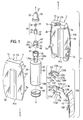
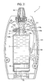
- FIGURES 1 to 3 show a fluid dispenser 1 in accordance with the present invention whose underlying principle of operation is as described and claimed in International patent application Nos. WO-A-2004014566 and WO-A-2004014567 .
- the fluid dispenser 1 has an outer casing 3 comprising first and second outer casing halves 5a, 5b.
- the outer casing 3 is assembled through the interengagement of complementary male and female connectors 7a, 7b formed on the inner surfaces 9a, 9b of the outer casing halves 5a, 5b.
- the male connectors 7a are pegs and the female connectors 7b are apertures into which the pegs are slidably receivable.
- the outer casing 3 is preferably made from a plastics material, for instance by moulding. Most preferably, the outer casing is made from acrylonitrile-butadiene-styrene (ABS).
- ABS acrylonitrile-butadiene-styrene
- the outer casing 3 of the fluid dispenser 1 is held in the hand H of a human user when operating the fluid dispenser 1.
- the user's hand H which holds the outer casing 3 is also able to be used to actuate the fluid dispenser 1, as will be understood further hereinafter.
- the outer casing halves 5a, 5b have a shell-like form whereby when assembled they enclose an internal chamber 11.
- an upper end 13 of the outer casing 3 there is a passageway 15 to the internal chamber 11 bounded by concave recesses 17a, 17b in the outer casing halves 5a, 5b.
- the passageway 15 is coaxially arranged with a longitudinal axis X-X of the fluid dispenser 1 and has a generally circular lateral cross section.
- the passageway 15 receives a nozzle 19 of the fluid dispenser 1, which in this embodiment is shaped and sized for insertion into a nostril of a human user (i.e. a nasal nozzle).
- the fluid dispenser 1 is an intra-nasal fluid dispenser.
- the nasal nozzle 19 in this particular embodiment has an outer surface 20 which has a generally circular lateral cross section and which curves laterally inwardly in the upward direction denoted by arrow U.
- the nasal nozzle 19 is preferably made from a plastics material, for instance from polypropylene (PP), and may, for example, be formed by moulding.
- PP polypropylene
- the nasal nozzle 19 is axially aligned with the longitudinal axis X-X and has a longitudinal bore 21 to direct the liquid dispensed from the dispenser 1 in the upward direction U along the longitudinal axis X-X.
- the nasal nozzle 19 has a generally cylindrical, open-ended inner tubular section 23 whose inner circumferential surface 25 defines the nozzle bore 21.
- the tubular section 23 provides an upper opening 27 of the nozzle bore 21 which is the outlet orifice of the fluid dispenser 1.
- the nasal nozzle 19 can be of other shapes and configurations suited for insertion into a human nostril.
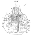
- a generally cylindrical valve body 28 of a one-way (non-return), poppet-type outlet valve 30 is fixedly, sealingly secured on an outer circumferential surface 29 of the nozzle inner tubular section 23 at its lower end 31 so that a lateral lower end wall 34 of the generally U-shaped valve body 28 is disposed underneath a lower opening 32 of the nozzle bore 21.
- the lateral lower end wall 34 of the valve body 28 includes a valve opening 33 and an outlet valve control member 35 operates in use to selectively place the outlet valve opening 33 and the nozzle bore 21 in flow communication so that a metered volume (metered dose) of the liquid 2 is able to flow through the outlet valve 30 into the nozzle bore 21, as will be described in more detail hereinafter.
- the outlet valve control member 35 has a generally cylindrical, tubular stem which is open at its upper end and closed by a flange plate at its lower end. One or more apertures 40 are provided in the tubular stem.
- the tubular stem is sealingly, slidably mounted in the lower opening 32 of the nozzle bore 21.
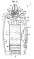
- the outlet valve control member 35 is biased by an outlet valve return spring 38, preferably integrally formed with the outlet valve control member 35, to a rest position in which the flange plate of the outlet valve control member 35 sealingly closes the valve opening 33 by seating on a valve seat 36, as shown in FIGURE 2A .
- the outlet valve control member 35 is lifted off the valve seat 36 to place the valve opening 33 in flow communication with the nozzle bore 21 through the one or more apertures 40 in the tubular stem of the outlet valve control member 35, as will be described in more detail hereinafter, particularly with reference to FIGURE 3 .
- the components 28,35 of the metering valve 30 may be made from polypropylene (PP), for example by moulding.
- the valve body 28 has an outer circumferential surface 37 on which is provided upper and lower sealing rings 39, 41.
- the upper and lower sealing rings 39, 41 may be integrally formed with the valve body 28 or be separate valve components.
- a generally U-shaped sliding member 43 is sealingly, slidably mounted on the outer circumferential surface 37 of the U-shaped valve body 28 for reciprocation along the longitudinal axis X-X between upper and lower positions relative to the U-shaped valve body 28. More particularly, the U-shaped sliding member 43 has a generally circular, longitudinal side wall 45 having an inner circumferential surface 47 which sealingly slides over the upper and lower sealing rings 39, 41 on the valve body 28. The U-shaped sliding member 43 further has a lateral lower end wall 49 which, in the upper position, abuts with the lateral lower end wall 34 of the valve body 28 (see e.g.
- FIGURES 2A , 2B and 2F to 2I which, in the lower position ( FIGURES 2D and 2E ), is spaced downwardly from the lateral lower end wall 34 of the valve body 28. It can therefore be seen that the U-shaped valve body 28 and the U-shaped sliding member 43 are arranged in a nesting configuration.
- the longitudinal side wall 45 of the U-shaped sliding member 43 has an outwardly extending connector flange 51 at an intermediate position of its outer circumferential surface 53.
- four equiangularly spaced transfer ports 55a, 55b extend laterally through the longitudinal side wall 45 of the U-shaped sliding member 43 at a position below the connector flange 51.
- the number of transfer ports can be decreased or increased as desired.
- the U-shaped sliding member 43 is made from a plastics material, e.g. by moulding.
- a preferred plastics material is polypropylene (PP).
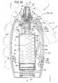
- a generally cylindrical, liquid-containing hollow container 57 is affixed to the U-shaped sliding member 43 so as to reciprocate therewith on the longitudinal axis X-X.
- the container 57 has an open-ended container body 56 having a generally U-shaped head 59 at an upper end 61 which nests with the U-shaped sliding member 43 to be fixedly, sealingly engaged with the connector flange 51 of the U-shaped sliding member 43, e.g. by adherence therebetween.
- connection is such that the lower section 60 of the outer circumferential surface 53 of the U-shaped sliding member 43, which is below the connector flange 51, is spaced laterally inwardly of the inner circumferential surface 62 of the U-shaped container head 59 so as to form an annular channel 64 therebetween, which is sealingly closed off at the upper end 61 by the connector flange 51 and into which the transfer ports 55a, 55b open.
- the container body 56 further has an enlarged hollow base 63 at a lower end 65 and a hollow neck 67 which extends longitudinally from the base 63 to the head 59.
- a sealing piston 69 is sealingly, slidably mounted in the container body base 63 to sealingly close the container body 56 at the lower end 65.
- the container body 56 is made from glass, although, of course, other inert materials may be used, for example a plastics material, such as polypropylene (PP). Where the container body 56 is made from a plastics material, it can be connected to the flange 51 of the plastics U-shaped sliding member 43 by welding, e.g. by ultrasonic welding.
- PP polypropylene
- the sealing piston 69 is made from a plastics material, e.g. by moulding, and is preferably made from butyl rubber.
- the container 57 contains a liquid medicament formulation.
- the lower end of the annular channel 64 about the U-shaped sliding member 43 is in flow communication with the inner volume of the container body neck 67 which in turn is in flow communication with the inner volume of the closed container body base 63.
- the container 57 co-operates with the sliding member 43 to define a container inner volume 71 which is only open at the transfer ports 55a, 55b due to the inner volume 71 being sealed by the sealing piston 69 at the lower end 65 and by the connector flange 51 at the upper end 61.
- the assembly of the U-shaped sliding member 43 and the container 57 will now be referred to as the "container unit 58".
- the U-shaped sliding member 43 and the lateral lower end wall 34 of the metering valve body 28 co-operate to define a pumping metering chamber 73 therebetween which is either sealed or selectively open to the transfer ports 55a, 55b or the nozzle bore 21 depending on the sliding position of the container unit 58 on the valve body 28, as will be detailed further hereinafter.
- the fluid dispenser 1 is filled with sufficient liquid 2 that, before it is first used, it completely fills the container inner volume 71, including the annular channel 64. Moreover, the fluid dispenser operation is such that the container inner volume 71 is kept airless, i.e. there is no headspace.
- a return spring 75 of compression type acts on the container base 63 to bias the container unit 58 in the upward direction U to an upper sliding position in the outer casing 3 in which the U-shaped sliding member 43 is disposed in its upper position on the valve body 28.
- the fluid dispenser 1 is adapted so that, in its rest or non-actuated state, the container unit 58 is placed in the upper sliding position by the return spring 75.
- the upper sliding position of the container unit 58 is defined by the abutment of the lateral lower end wall 49 of the U-shaped sliding member 43 with the lateral lower end wall 34 of the valve body 28 (i.e. when the U-shaped sliding member 43 is in its upper sliding position on the valve body 28).
- the pumping metering chamber 73 has no, or substantially no, volume in the rest state of the fluid dispenser 1.
- the transfer ports 55a, 55b are disposed in-between the upper and lower sealing rings 39, 41 on the valve body 28.
- the outlet valve control member 35 is in its closed position. Consequently, the metering chamber 73 is not in flow communication with the inner volume counter 71 of the container 57 nor with the nozzle bore 21. That is to say, the metering chamber 73 is sealed.
- the inner volume 71 of the container unit 58 is completely sealed in the rest state of the fluid dispenser 1 inasmuch as contaminants, such as air and moisture, cannot enter the container inner volume 71 at its lower end 65, due to the sealing piston 69, nor at the upper end 61 by virtue of the position of the transfer ports 55a, 55b between the sealing rings 39, 41, the collapsed state of the metering chamber 73 and the closed position of the outlet valve control member 35.
- the components of the fluid dispenser 1 are made from fluid impervious materials.
- the fluid dispenser 1 is provided with a hand-operable actuating mechanism 100 for reciprocating the container unit 58 along the longitudinal axis X-X to cause a metered dose of the liquid 2 to be dispensed.
- the actuating mechanism 100 drives the container unit 58 downwardly in the direction of arrow D against the return force of the return spring 75.
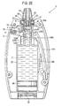
- the U-shaped sliding member 43 parts from the valve body 28 so as to increase the volume of the metering chamber 73, as shown in FIGURES 2C to 2E .
- the transfer ports 55a, 55b slide past the lower sealing ring 41 to place the metering chamber 73 and the container inner volume 71 in flow communication with one another. Liquid from the container 57 is then drawn into the metering chamber 73 due to the negative pressure created in the metering chamber 73 during the downward stroke of the container unit 58.
- the sealing piston 69 slides up in the container base 63, under the influence of the negative pressure, to decrease the inner volume 71 of the container 57 by an amount equivalent to the liquid volume transferred into the metering chamber 73. Accordingly, no headspace is generated over the liquid 2 in the container 57 during the filling of the metering chamber 73.
- outlet valve control member 35 remains closed in the downward stroke to prevent escape of any of the liquid 2 transferred into the metering chamber 73 during this filling mode of operation of the fluid dispenser 1.
- the sealing piston 69 moves downwardly to a new rest position which is spaced upwardly of its previous rest position before the filling mode of operation.
- the increase in the container inner volume 71 in the bleed mode is equivalent to the volume of liquid bled back thereinto. Thus, no headspace is created in the container inner volume 71 in the bleed mode.
- the transfer ports 55a, 55b are juxtaposed with the lower sealing ring 41 so as to be closed thereby.
- the metering chamber 73 now defines the metering volume of the fluid dispenser 1 and is filled with a metered volume of the liquid 2 transferred thereinto during the filling mode of operation.
- the metering volume is 50 ⁇ L, although, of course, the fluid dispenser 1 can be made to produce other metering volumes depending on the specific application and/or product to be dispensed.
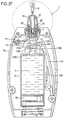
- the volume of the metering chamber 73 continues to reduce to increase the hydraulic pressure therein causing the outlet valve control member 35 to lift off the outlet valve seat 36 and the metered volume of liquid 2 to be pumped from the metering chamber 73 out of the dispenser outlet orifice 27 via the nozzle bore 21.
- This is the dispensing mode of operation of the fluid dispenser 1 and is shown schematically in FIGURE 3 .
- the outlet valve control member 35 re-closes the outlet valve opening 33.
- an actuation cycle of the fluid dispenser 1 results in the sealing piston 69 moving upwardly by an amount which results in the container inner volume 71 reducing by the metered volume. This ensures that no headspace is provided in the container inner volume 71 thereby ensuring no air is present therein. Accordingly, repeated use of the fluid dispenser 1 causes the sealing piston 69 to move incrementally upwardly until it bears against the roof 66 of the container base 63 whereupon no further dispensing takes place.
- the pumping force of the fluid dispenser 1 is such as to produce an atomised spray having a relative small and uniform droplet size ideal for delivery to the nasal passage of the user.
- the fluid dispenser 1 may be adapted to dispense the metered volume as a spray of droplets having a diameter in the range of 10-20 ⁇ m.
- each further actuation of the actuating mechanism 100 results in this cycle of events being repeated until the sealing piston 69 abuts the roof 66 of the container base 63.
- the inner volume 71 of the container base 63 which corresponds to the volume of liquid 2 that is dispensable from the fluid dispenser 1, is 14ml. Consequently, the fluid dispenser 1 has 280 actuations.
- the container 57 can be filled with the liquid 2 after it has been assembled into the fluid dispenser 1 by forming the sealing piston 69 so that it is able to be sealingly pierced by a needle-like object and then sealably reclose after withdrawal of the needle-like object (e.g. a "septum").
- the needle-like object e.g. a "septum”
- the liquid could be injected through the sealing piston 69.
- the outer casing halves 5a, 5b each have a base with a concave cut-out 81 a, 81 b which, when the outer casing 3 is assembled, provide an aperture in the outer casing base. The injector could be inserted through the sealing piston 69 via this aperture.
- the actuation mechanism is lever-based in the sense that actuation is effected through an actuation lever 101 which is mounted to the outer casing 3 in a longitudinal slot 102 thereof formed by the junction of opposed sides of the outer casing halves 5a, 5b.
- the actuation lever 101 has a lower end 103 which is pivotally connected to the outer casing 3 at a pivot point 105 for pivotal movement about a first lateral pivot axis P1-P1.
- the actuation lever 101 has an inner surface 107 from which depends a return leaf spring 108.
- the return leaf spring 108 which is preferably an integrally formed part of the lever 101, co-operates with the container base 63 to bias the actuation lever 101 to an outward rest position in which it forms a flush fit in the outer casing 3, as shown in FIGURE 2A , for example. This is the position the actuation lever 101 adopts in the non-actuated or rest state of the fluid dispenser 1.
- the user picks up the fluid dispenser 1 in their hand H and pushes the actuation lever 101 from its outward rest position into the outer casing 3 to cause it to pivot about the first pivot axis P1-P1 against the return force of the leaf spring 108.
- the user uses a digit of the hand H holding the fluid dispenser 1 to push the actuation lever 101 inwardly, in this instance their thumb T.
- the actuation lever 101 is returned to the outward return position upon release, or relaxation, of the pushing force F on the actuation lever 101 by the return spring 108.
- the user pushes the actuation lever 101 inwardly after the nozzle 19 has been inserted into one of their nostrils.
- a laterally extending drive structure 109 which is so constructed and arranged in the fluid dispenser 1 to transmit the inward pivotal motion of the actuation lever 101 into a downward driving force on the container unit 58 to effect the downward stroke thereof, as described hereinabove.
- the drive structure 109 has a generally U-shaped outer carrier frame 111 pivotally connected to the actuation lever 101 for pivotal movement about a second lateral pivot axis P2-P2 which extends generally parallel to the first pivot axis P1-P1.
- the U-shaped outer carrier frame 111 has a pair of generally parallel side members 113a, 113b which straddle the neck 67 of the container 57 on opposed sides thereof and are connected at first ends thereof to pivot points 115a, 115b on the actuation lever inner surface 107, and a crossbar member 117 which connects the side members 113a, 113b at second ends thereof.
- the U-shaped outer carrier frame 111 forms a hollow box-like structure with the actuation lever 101 which encloses the neck 67 of the container 57.
- the U-shaped outer carrier frame 111 further has a return leaf spring 119a, 119b depending from the first end of each side member 113a, 113b which co-operates with the inner surface 107 of the actuation lever 101 to bias the U-shaped carrier frame 111 to an upper pivot position which, for example, is shown in FIGURE 2A .
- the drive structure 109 further comprises a generally U-shaped inner cam frame 121 which is carried by the U-shaped outer carrier frame 111 on the inside thereof.
- the inner cam frame 121 has a pair of generally parallel side members 123a, 123b which are arranged generally parallel to the side members 113a, 113b of the outer carrier frame 111.
- the inner cam frame side members 123a, 123b are each provided with an outwardly projecting lug 125a, 125b at a first end thereof which is received in a longitudinal slide aperture 127a, 127b formed in the adjacent outer carrier frame side member 113a, 113b between the first and second ends thereof.
- the inner cam frame side members 123a, 123b are also each provided with an inwardly projecting cam element 129a, 129b of wing-like cross-section, the function of which will be outlined further hereinafter.
- the inner cam frame 121 further has a crossbar member 131 which connects the side members 123a, 123b at second ends thereof.
- the inner cam frame crossbar member 131 is configured as a C-shape clip which clips to the crossbar member 117 of the outer carrier frame 111 to enable the inner cam frame 121 to be pivotal thereabout.
- the pivotal movement of the inner cam frame 121 on the outer carrier frame 111 is governed by sliding movement of the lugs 125a, 125b in the associated slide apertures 127a, 127b.
- the end limits of the pivotal movement of the inner cam frame 121 about the crossbar member 117 of the outer carrier frame 111 between lower and upper pivot positions are respectively determined by the abutment of the lugs 125a, 125b with the lower and upper ends of the longitudinal slide apertures 127a, 127b.
- the inner cam frame 121 yet further comprises a return leaf spring 133a, 133b projecting upwardly from each opposing end of the crossbar member 131.
- the return leaf springs 133a, 133b of the inner cam frame 121 each co-operate with an abutment surface 134 on the adjacent outer carrier frame side member 113a, 113b to bias the inner cam frame 121 in the downward direction D to its lower pivot position.
- the lugs 125a, 125b of the inner cam frame 121 are held against the lower ends of the slide apertures 127a, 127b of the outer carrier frame 111.
- the function of the inner cam frame 121 is to convert the inward movement of the actuation lever 101 into a downward camming action on the container unit 58 and thereby place the fluid dispenser 1 in its filling mode.
- a pair of diametrically opposed peg-shaped cam followers 135a, 135b extend laterally from the neck 67 of the container 57.
- the cam followers 135a, 135b and cam elements 129a, 129b on the inner cam frame 121 co-operate to produce the downward stroke of the container unit 58 representing the filling mode, as will now be described in more detail.
- the component parts thereof adopt the relative positions shown in FIGURE 2A .
- the container unit 58 is held in its upper slide position by the return spring 75, the actuation lever 101 is in its outward pivot position, the outer carrier frame 111 is in its upper pivot position and the inner cam frame 121 is in its lower pivot position.
- the actuation lever 101 is pivoted inwardly, as discussed previously, and this pivotal inward movement is transmitted to the drive structure 109 causing it to be displaced laterally inwardly.
- the inner carrier frame 121 is moved from its lower pivot position relative to the outer carrier frame 111 to its upper pivot position as a result of the cam elements 129a, 129b riding up the upper surfaces of the cam followers 135a, 135b.
- the lugs 125a, 125b are caused to slide upwardly in the slide apertures 127a, 127b from the lower end of the slide apertures 127a, 127b to the upper ends with concomitant compression of the inner cam frame leaf springs 133a, 133b.
- the inner carrier frame 121 is "locked" in its upper pivot position.
- FIGURE 3 shows in detail how the outlet valve control member 35 is lifted off the outlet valve seat 36 during the dispensing mode by the hydraulic pressure built up in the metering chamber 73 once the metering chamber 73 is sealed after the bleed mode. As indicated by the arrows, this allows the liquid 2 to be pumped through the outlet valve aperture 33, around the side of the outlet valve control member 35, through the aperture(s) 40 in the outlet valve control member 35 and out of the outlet orifice 27 via the nozzle bore 21.
- the inward movement of the drive structure 109 is delimited by abutment of the crossbar 131 of the inner cam frame 121 with an inner surface of the outer casing 3.
- FIGURES 2G to 2I This sequence is shown in FIGURES 2G to 2I from which it will be noted that, in an initial phase of the concomitant returning outward movement of the drive structure 109, the cam elements 129a, 129b re-engage the cam followers 135a, 135b, albeit this time riding over the lower cam follower surfaces due to the lugs 125a, 125b now being at the lower ends of the slide apertures 127a, 127b. Moreover, for the same reason, the outer carrier frame 111 tilts to its lower pivot position on the actuation lever 101.
- the cam elements 129a, 129b Towards the end of the return movement of the actuation mechanism 100 to its rest state, the cam elements 129a, 129b disengage from the cam followers 135a, 135b thereby enabling the outer carrier frame 111 and inner cam frame 121 to return to their respective rest states.
- the actuation lever 101, the outer carrier frame 111 and the inner cam frame 121 are made from a plastics material, for instance ABS, as an example by moulding.
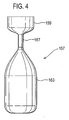
- the container 57 may be replaced by a bag structure which would contract and expand in equivalent fashion, and for equivalent function, as the container 57, e.g. by being made from a flexible material, for instance a plastics material.
- a bag structure over the container 57 would be that it avoids the need for a complex structure for contraction and expansion of its inner volume.
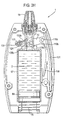
- FIGURE 4 An example of a bag container 157 is shown in FIGURE 4 with like reference numerals indicating like features in the container 57 of FIGURES 1 to 3 .
- the bag container 157 has a head 159 and a neck 167 corresponding to those in the container 57.
- the base 163 of the bag container 157 is formed by a bag element which expands/contracts depending on the mode of operation of the fluid dispenser 1.
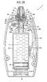
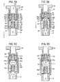
- FIGURES 5A to 5G there is shown an alternative valve arrangement for use in the fluid dispenser 1 of FIGURES 1 to 3 .
- those features in the alternative valve arrangement which are equivalent to features of the valve arrangement shown in FIGURES 1 to 3 are ascribed like reference numerals.
- a relief inlet valve 150 is positioned between the metering chamber 73 and the inner volume 71 of the container 57 which remains closed other than when the downstroke of the container unit 58 is initiated whereupon it is temporarily caused to open by the reduced pressure created in the metering chamber 73 during this phase.
- This allows liquid 2 to enter the metering chamber 73 before the transfer ports 55a-c (three shown this time) are placed in flow communication with the metering chamber 73.
- This makes it easier to move the container unit 58 in the downward direction D against the reduced pressure in the metering chamber 73 until the transfer ports 55a-c are opened, whereupon liquid 2 enters the metering chamber 73 therethrough.
- Filling of the metering chamber 73 then continues through the transfer ports 55a-c as previously described with reference to FIGURES 1 to 3 .
- the inlet valve 150 has an inlet valve opening 151 in the lateral lower end wall 49 of the U-shaped sliding member 43 and an inlet valve control element 153 slidably, sealingly mounted in the inlet valve opening 151 for movement between a closed position, shown in FIGURE 5A , in which the inlet valve control element 153 is seated on an inlet valve seat 152 to shut the inlet valve opening 151 to prevent flow communication between the metering chamber 73 and the inner volume 71 of the container 57, and an open position, shown in FIGURE 5B , in which the inlet valve control element 153 moves off the inlet valve seat 152 to open the inlet valve opening 151 to put the metering chamber 73 and the inner volume 71 of the container 57 in flow communication.
- the inlet valve 150 further has a return spring 155 which biases the inlet valve control element 153 to its closed position.
- FIGURE 5A shows that the inlet valve control element 153 is biased by the return spring 155 to the closed position in the rest state of the fluid dispenser 1.
- the U-shaped sliding member 43 is moved downwardly with respect to the outlet valve body 28 causing the metering chamber 73 to expand from its contracted state.
- the reduced or negative pressure this creates in the metering chamber 73 draws the inlet valve control element 153 up off the inlet valve seat 152 to its open position against the return force of the inlet valve return spring 155.
- the reduced pressure in the metering chamber 73 then draws liquid 2 into the metering chamber 73 from the container 57 through the inlet valve opening 151, as shown in FIGURE 5B .
- the transfer ports 55a-c are still shut in the sense that they have not travelled below the lower sealing ring 41.
- the metering chamber 73 continues to expand and draw in liquid 2 through the inlet valve 150 until the transfer ports 55a-c open so liquid 2 can be drawn into the metering chamber 73 through these, as shown in FIGURE 5C .
- the return force of the inlet valve return spring 155 biases the inlet valve control element 153 back onto the inlet valve seat 152 to close the inlet valve aperture 151.
- the metering chamber 73 is then filled up through the transfer ports 55a-c as the U-shaped sliding member 43 completes its downward stroke.
- the outlet valve 130 remains shut during the whole of the downward stroke. Specifically, the outlet valve control element 135 is biased by the outlet valve return spring 138 into sealing engagement in the outlet valve aperture 133 (the closed position).
- FIGURES 5E to 5G depict the upward stroke of the container 57 from which it will be seen that the inlet valve 150 stays shut.
- FIGURES 5F and 5G show that after the transfer ports 55a-c are re-closed by the lower sealing ring 41, the hydraulic pressure in the metering chamber 73 is sufficient to open the outlet valve 130 to enable discharge of the metered volume contained in the metering chamber 73.
- the hydraulic pressure created in the metering chamber 73 forces the outlet valve control element 135 to slide upwardly in the outlet valve aperture 133 against the biasing force of the outlet valve return spring 138 to enable the liquid in the metering chamber 73 to pass through the outlet valve 130 to the outlet orifice 27 (the open position).
- the outlet valve return spring 138 returns the outlet valve control element 135 to its closed position.
- the outlet and inlet valve control members 135, 153 may be made from a plastics material, such as polypropylene (PP), for example by moulding.
- PP polypropylene
- the fluid dispense 1 described above provides for high accuracy dosing from a sealed system which protects the liquid 2 from contamination from the external environment.
- the non-return outlet valve 30; 130 prevents air ingress.
- the container inner volume 71 is isolated from the outlet orifice 27 by the outlet valve 30; 130 and the closure of the outlet valve aperture 33 by the U-shaped sliding member 43 in the rest state of the dispenser. Accordingly, the liquid can be preservative-free, of particular benefit when the liquid is a medicament.
- the dispenser 1 further dispenses without the need for a dip tube, and there is no drain back.
- the dispenser of the invention is a medicament dispenser, for instance an intra-nasal medicament dispenser
- administration of the medicament may be indicated for the treatment of mild, moderate or severe acute or chronic symptoms or for prophylactic treatment.
- Appropriate medicaments may thus be selected from, for example, analgesics, e.g., codeine, dihydromorphine, ergotamine, fentanyl or morphine; anginal preparations, e.g., diltiazem; antiallergics, e.g., cromoglycate (e.g. as the sodium salt), ketotifen or nedocromil (e.g.
- analgesics e.g., codeine, dihydromorphine, ergotamine, fentanyl or morphine
- anginal preparations e.g., diltiazem
- antiallergics e.g., cromoglycate (e.g. as the sodium salt), ketotifen or nedocromil (e.g.
- antiinfectives e.g., cephalosporins, penicillins, streptomycin, sulphonamides, tetracyclines and pentamidine
- antihistamines e.g., methapyrilene
- anti- inflammatories e.g., beclomethasone (e.g. as the dipropionate ester), fluticasone (e.g. as the propionate ester), flunisolide, budesonide, rofleponide, mometasone (e.g. as the furoate ester), ciclesonide, triamcinolone (e.g.
- fenoterol e.g. as hydrobromide
- formoterol e.g. as fumarate
- isoprenaline metaproterenol
- phenylephrine phenylpropanolamine
- pirbuterol e.g. as acetate
- reproterol e.g. as hydrochloride
- rimiterol terbutaline
- bromide as bromide
- tiotropium as bromide
- atropine or oxitropium hormones, e.g., cortisone, hydrocortisone or prednisolone
- xanthines e.g., aminophylline, choline theophyllinate, lysine theophyllinate or theophylline
- therapeutic proteins and peptides e.g., insulin or glucagons.
- the medicaments may be used in the form of salts, (e.g., as alkali metal or amine salts or as acid addition salts) or as esters (e.g., lower alkyl esters) or as solvates (e.g., hydrates) to optimise the activity and/or stability of the medicament and/or to minimise the solubility of the medicament in the propellant.
- salts e.g., as alkali metal or amine salts or as acid addition salts
- esters e.g., lower alkyl esters
- solvates e.g., hydrates
- the medicament is an anti-inflammatory compound for the treatment of inflammatory disorders or diseases such as asthma and rhinitis.
- the medicament may be a glucocorticoid compound, which has anti-inflammatory properties.
- One suitable glucocorticoid compound has the chemical name: 6 ⁇ , 9 ⁇ -Difluoro-17 ⁇ -(1-oxopropoxy)-11 ⁇ -hydroxy-16 ⁇ -methyl-3-oxo-androsta-1,4-diene-17 ⁇ -carbothioic acid S-fluoromethyl ester (fluticasone propionate).
- Another suitable glucocorticoid compound has the chemical name: 6 ⁇ , 9 ⁇ -difluoro-17 ⁇ -[(2-furanylcarbonyl)oxy]-11 ⁇ -hydroxy-16 ⁇ -methyl-3-oxo-androsta-1,4-diene-17 ⁇ -carbothioic acid S-fluoromethyl ester.
- a further suitable glucocorticoid compound has the chemical name: 6 ⁇ ,9 ⁇ -Difluoro-11 ⁇ -hydroxy-16 ⁇ -methyl-17 ⁇ -[(4-methyl-1,3-thiazole-5-carbonyl)oxy]-3-oxo-androsta-1,4-diene-17 ⁇ -carbothioic acid S-fluoromethyl ester.
- NSAIDs e.g. PDE4 inhibitors, leukotriene antagonists, iNOS inhibitors, tryptase and elastase inhibitors, beta-2 integrin antagonists and adenosine 2a agonists.
- the medicament is formulated as any suitable fluid formulation, particularly a solution (e.g. aqueous) formulation or a suspension formulation, optionally containing other pharmaceutically acceptable additive components.
- a suitable fluid formulation particularly a solution (e.g. aqueous) formulation or a suspension formulation, optionally containing other pharmaceutically acceptable additive components.
- the formulation may contain a preservative, although the sealed system of the dispenser may negate the need for this.
- the medicament formulation may incorporate two or more medicaments.
- the dispenser herein is suitable for dispensing fluid medicament formulations for the treatment of inflammatory and/or allergic conditions of the nasal passages such as rhinitis e.g. seasonal and perennial rhinitis as well as other local inflammatory conditions such as asthma, COPD and dermatitis.
- rhinitis e.g. seasonal and perennial rhinitis
- other local inflammatory conditions such as asthma, COPD and dermatitis.
- a suitable dosing regime would be for the patient to inhale slowly through the nose subsequent to the nasal cavity being cleared. During inhalation the formulation would be applied to one nostril while the other is manually compressed. This procedure would then be repeated for the other nostril. Typically, one or two inhalations per nostril would be administered by the above procedure up to three times each day, ideally once daily. Each dose, for example, may deliver 5 ⁇ g, 50 ⁇ g, 100 ⁇ g, 200 ⁇ g or 250 ⁇ g of active medicament. The precise dosage is either known or readily ascertainable by those skilled in the art.
- the dispenser of the invention need not be hand-held, nor hand-operable.
- the dispenser may be used to deliver any number of different fluid products, medicinal and non-medicinal, as outlined previously.
- the dispenser may form an internal part of a device unit so that the dispenser delivers a metered volume of the fluid product to another internal part of the device unit.
- the unit may be a dispenser unit including the dispenser and the metered volume is delivered to conveying means in the dispenser unit which conveys the fluid product to an outlet orifice of the unit for discharge from the unit to the surrounding environment.
- the conveying means may be such as to change the state of the fluid, e.g. the conveying means may have a vibrating element, e.g. a mesh, which converts a metered volume of liquid to an aerosol or mist which is then directed out of the outlet orifice.
- the vibrating element could, for example, be a piezoelectric element or mesh.
Claims (97)
- Fluidspender (1) zum Abgeben eines abgemessenen Volumens eines fluiden Produkts (2), mit:(a) einer Lagerkammer (57) zum Lagern des fluiden Produkts darin;(b) einem Abgabeauslass (27), durch welchen das fluide Produkt aus dem Spender abgebbar ist;(c) einer Messkammer (73), die geeignet ist, ein abgemessenes Volumen des fluiden Produkts zum Abgeben durch den Abgabeauslass bereitzustellen, durch eine Bewegung der Messkammer zwischen einem zusammengezogenen Zustand und einem erweiterten Zustand, wobei eine Bewegung der Messkammer aus dem zusammengezogenen Zustand in den erweiterten Zustand die Messkammer und die Lagerkammer in Fluid-Verbindung platziert, um zu ermöglichen, dass die Messkammer von der Lagerkammer ein Überschussvolumen des fluiden Produkts empfängt, welches das abgemessene Volumen und ein Mehrvolumen umfasst; und(d) einer Nebenleitungsanordnung (55a, 55b), die geeignet ist, das Mehrvolumen des fluiden Produkts aus der Messkammer abzulassen; wobei(e) die Messkammer durch eine Grenzwand definiert ist, die einen ersten Abschnitt (43) aufweist, der bewegbar in dem Spender angebracht ist, um die Messkammer zwischen dem erweiterten und dem zusammengezogenen Zustand zu bewegen; und(f) wobei zumindest eine Transferöffnung (55a, 55b) in dem ersten Abschnitt der Messkammer-Grenzwand ausgebildet ist, durch welche das fluide Produkt von der Lagerkammer zu der Messkammer überführbar ist, wenn sich die Messkammer in den erweiterten Zustand bewegt.
- Spender nach Anspruch 1, bei dem der erste Abschnitt der Messkammer-Grenzwand und die Lagerkammer durch eine Behältereinheit vorgesehen sind, die in dem Spender bewegbar angebracht ist.
- Spender nach Anspruch 1 oder 2, bei dem die Transferöffnung selektiv geöffnet und geschlossen wird, wenn sich die Messkammer zwischen ihrem erweiterten und ihrem zusammengezogenen Zustand bewegt.
- Spender nach Anspruch 1, 2 oder 3, bei dem die Transferöffnung geschlossen ist, wenn die Messkammer in einem Zwischenzustand zwischen ihrem erweiterten und ihrem zusammengezogenen Zustand ist.
- Spender nach Anspruch 4, bei dem die Messkammer ein Volumen aufweist, das dem abgemessenen Volumen entspricht, oder im Wesentlichen entspricht, wenn sie in dem Zwischenzustand ist.
- Spender nach Anspruch 4 oder 5, bei dem die Transferöffnung geschlossen ist, wenn sich die Messkammer zwischen dem Zwischenzustand und dem zusammengezogenen Zustand bewegt, und offen, wenn sich die Messkammer zwischen dem Zwischenzustand und dem erweiterten Zustand bewegt.
- Spender nach einem der vorhergehenden Ansprüche, bei dem die Grenzwand einen zweiten Abschnitt aufweist, und die Messkammer zwischen ihrem erweiterten und ihrem zusammengezogenen Zustand durch eine Bewegung des ersten Abschnitts in dem Spender relativ zu dem zweiten Abschnitt bewegbar ist.
- Spender nach Anspruch 7, bei dem der zweite Abschnitt stationär in dem Spender ist.
- Spender nach Anspruch 7 oder 8, bei Abhängigkeit von Anspruch 3, bei dem der zweite Abschnitt geeignet ist, bei der Verwendung, die Transferöffnung selektiv zu öffnen und zu schließen.
- Spender nach einem der vorhergehenden Ansprüche, bei dem eine Auslassöffnung in der Grenzwand vorgesehen ist, durch welche das fluide Produkt von der Messkammer zu dem Abgabeauslass hin überführbar ist.
- Spender nach Anspruch 10, bei Abhängigkeit von Anspruch 7 oder 8, bei dem die Auslassöffnung in dem zweiten Abschnitt vorgesehen ist.
- Spender nach Anspruch 2, oder einem davon abhängigen Anspruch, bei dem die Behältereinheit geeignet ist, bei der Verwendung, als ein Pumpenmechanismus zum Füllen und Entleeren der Messkammer betrieben zu werden.
- Spender nach einem der vorhergehenden Ansprüche, bei dem eine Bewegung der Messkammer aus ihrem zusammengezogenen Zustand in ihren erweiterten Zustand einen Druckunterschied zwischen der Messkammer und der Lagerkammer bewirkt, welcher dazu führt, dass das Überschussvolumen des fluiden Produkts in die Messkammer gezogen wird.
- Spender nach einem der vorhergehenden Ansprüche, bei dem eine Bewegung der Messkammer aus ihrem erweiterten Zustand in ihren zusammengezogenen Zustand das abgemessene Volumen des fluiden Produkts aus der Messkammer pumpt.
- Spender nach einem der vorhergehenden Ansprüche, bei dem die Messkammer wiederholt zwischen ihren unterschiedlichen Zuständen bewegbar ist, wodurch ermöglicht wird, dass der Spender wiederholt ein abgemessenes Volumen des fluiden Produkts abgibt.
- Spender nach einem der vorhergehenden Ansprüche, ferner mit einem Ventilmechanismus, der geeignet, bei der Verwendung, den Abgabeauslass geschlossen zu halten, bis die Nebenleitungsanordnung das Mehrvolumen des fluiden Produkts aus der Messkammer ablässt.
- Spender nach Anspruch 16, bei dem der Ventilmechanismus geeignet ist, den Abgabeauslass zu öffnen, wenn sich die Messkammer in ihren zusammengezogenen Zustand bewegt, und den Abgabeauslass wieder zu verschließen, wenn der zusammengezogene Zustand erreicht ist.
- Spender nach Anspruch 10, Anspruch 11 oder einem der Ansprüche 12 bis 15, bei Abhängigkeit von Anspruch 10, ferner mit einem Ventilmechanismus an der Auslassöffnung, der geeignet ist, lediglich zuzulassen, dass das abgemessene Volumen des fluiden Produkts an den Abgabeauslass überführt wird.
- Spender nach Anspruch 18, bei dem der Ventilmechanismus ausgestaltet ist, die Auslassöffnung zu schließen, außer wenn sich die Messkammer in ihren zusammengezogenen Zustand bewegt, nachdem die Nebenleitungsanordnung das Mehrvolumen des fluiden Produkts daraus ablässt.
- Spender nach einem der Ansprüche 16 bis 19, bei dem der Ventilmechanismus ein Rückschlag-Ventilmechanismus ist.
- Spender nach einem der vorhergehenden Ansprüche, bei dem der Abgabeauslass in einer Düse des Spenders ist.
- Spender nach Anspruch 21, bei dem die Düse als ein Mundstück oder eine Nasendüse ausgestaltet ist.
- Spender nach einem der vorhergehenden Ansprüche, bei dem die Nebenleitungsanordnung geeignet ist, bei der Verwendung, das Mehrvolumen des fluiden Produkts in der Messkammer an die Lagerkammer abzulassen.
- Spender nach Anspruch 23, bei dem die Nebenleitungsanordnung geeeignet ist, bei der Verwendung, das Mehrvolumen des fluiden Produkts an die Lagerkammer durch die Transferöffnung abzulassen.
- Spender nach einem der vorhergehenden Ansprüche, bei dem die Lagerkammer geeignet ist, sich aus einem erweiterten Zustand in einen zusammengezogenen Zustand zu bewegen, als Reaktion darauf, dass das Überschussvolumen an die Messkammer überführt wird.
- Spender nach Anspruch 25, bei Abhängigkeit von Anspruch 23 oder 24, bei dem die Lagerkammer geeignet ist, sich zurück in einen erweiterten Zustand zu bewegen, als Reaktion darauf, dass das Mehrvolumen zurück darein abgelassen wird.
- Spender nach Anspruch 24, bei Abhängigkeit von einem der Ansprüche 16 bis 20, bei dem:die Lagerkammer geeignet ist,wobei der Ventilmechanismus einen Öffnungsdruck-Schwellenwert aufweist, der größer als der Druck ist, der benötigt wird, um die Lagerkammer in ihren erweiterten Zustand zurückzubringen, wodurch der Ventilmechanismus während des Ablassens des Mehrvolumens des fluiden Produkts geschlossen bleibt.(i) sich aus einem erweiterten Zustand in einen zusammengezogenen Zustand zu bewegen, als Reaktion darauf, dass das Überschussvolumen an die Messkammer überführt wird, durch eine Bewegung der Messkammer aus ihrem zusammengezogenen Zustand in ihren erweiterten Zustand, und(ii) zu einem erweiterten Zustand zurückzukehren, als Reaktion darauf, dass das Mehrvolumen zurück darein abgelassen wird, durch eine Bewegung der Messkammer aus ihrem erweiterten Zustand in ihren zusammengezogenen Zustand; und
- Spender nach Anspruch 26 oder 27, welcher derart angepasst ist, dass, bei der Verwendung, das Volumen des erweiterten Zustands der Lagerkammer vor einem Überführen des Überschussvolumens des fluiden Produkts an die Messkammer größer ist als das Volumen ihres erweiterten Zustands nach einem Recycling des Mehrvolumens darein.
- Spender nach einem der Ansprüche 25 bis 28, bei dem die Lagerkammer geeignet ist, sich zwischen ihrem erweiterten und ihrem zusammengezogenen Zustand durch Drücke zu bewegen, die durch eine Bewegung der Messkammer zwischen ihrem erweiterten und ihrem zusammengezogenen Zustand erzeugt werden.
- Spender nach einem der Ansprüche 25 bis 29, bei dem die Lagerkammer eine Grenzwand mit einem ersten und einem zweiten Abschnitt aufweist, die relativ zueinander bewegbar sind, um die Lagerkammer in ihren erweiterten und ihren zusammengezogenen Zustand zu bringen.
- Spender nach Anspruch 30, bei dem sich die Transferöffnung in dem ersten Abschnitt der Lagerkammer-Grenzwand befindet, wobei der zweite Abschnitt der Lagerkammer-Grenzwand von der Transferöffnung beabstandet ist.
- Spender nach Anspruch 31, welcher derart angepasst ist, dass, bei der Verwendung, der Abstand des zweiten Abschnitts der Lagerkammer-Grenzwand von der Transferöffnung nach jedem Bewegungszyklus der Messkammer zwischen ihrem erweiterten und ihrem zusammengezogenen Zustand abnimmt.
- Spender nach einem der Ansprüche 30 bis 32, bei dem der zweite Abschnitt der Lagerkammer-Grenzwand an dem ersten Abschnitt der Lagerkammer-Grenzwand gleitbar angebracht ist.
- Spender nach Anspruch 33, bei dem der zweite Abschnitt der Lagerkammer-Grenzwand eine Endwand der Lagerkammer präsentiert, die an dem ersten Abschnitt der Lagerkammer-Grenzwand abdichtend gleitbar angebracht ist.
- Spender nach einem der Ansprüche 30 bis 34, bei dem der erste Abschnitt der Lagerkammer-Grenzwand den ersten Abschnitt der Messkammer-Grenzwand umfasst.
- Spender nach Anspruch 2, oder einem davon abhängigen Anspruch, bei dem die Behältereinheit für eine translatorische Bewegung in dem Spender angebracht ist.
- Spender nach Anspruch 36, mit einer Achse, entlang welcher sich die Behältereinheit, bei der Verwendung, bewegt.
- Spender nach Anspruch 37, bei dem sich die Lagerkammer und die Messkammer auf der Achse befinden.
- Spender nach Anspruch 37 oder 38, bei Abhängigkeit von Anspruch 10, bei dem sich die Auslassöffnung auf der Achse befindet.
- Spender nach Anspruch 37, 38 oder 39, bei dem sich der Abgabeauslass auf der Achse befindet.
- Spender nach Anspruch 40, bei dem die Auslassöffnung und der Abgabeauslass an gegenüberliegenden Enden eines axialen Kanals des Spenders sind.
- Spender nach Anspruch 21, oder einem davon abhängigen Anspruch, bei dem die Lagerkammer, Messkammer und Düse in Reihe ausgestaltet sind.
- Spender nach Anspruch 10, oder einem davon abhängigen Anspruch, bei dem die Lagerkammer, Messkammer und Auslassöffnung in Reihe ausgestaltet sind.
- Spender nach Anspruch 7, oder einem davon abhängigen Anspruch, bei dem der erste Abschnitt der Messkammer-Grenzwand für eine Gleitbewegung auf dem zweiten Abschnitt der Messkammer-Grenzwand angebracht ist.
- Spender nach Anspruch 44, bei dem der erste Abschnitt der Messkammer-Grenzwand an dem zweiten Abschnitt der Messkammer-Grenzwand abdichtend gleitbar angebracht ist.
- Spender nach einem der Ansprüche 37 bis 41 und Anspruch 44 oder Anspruch 45, bei dem der erste Abschnitt der Messkammer-Grenzwand zumindest einen Teil einer axial ausgerichteten Seite der Messkammer präsentiert.
- Spender nach Anspruch 46, bei dem die Transferöffnung in der axial ausgerichteten Seite der Messkammer vorgesehen ist.
- Spender nach einem der vorhergehenden Ansprüche, bei dem der erste Abschnitt der Messkammer-Grenzwand eine bewegbare Endwand der Messkammer präsentiert.
- Spender nach einem der vorhergehenden Ansprüche, bei dem der erste Abschnitt der Messkammer-Grenzwand eine allgemeine U-Form aufweist.
- Spender nach Anspruch 46, 48 und 49, bei dem die Endwand der Messkammer durch die Basis der U-Form präsentiert ist, und die Seite der Messkammer durch die Schenkel der U-Form präsentiert ist.
- Spender nach Anspruch 46, 47 oder 50, bei Abhängigkeit von Anspruch 7, bei dem der zweite Abschnitt der Messkammer-Grenzwand durch eine Struktur mit einer axial ausgerichteten Oberfläche präsentiert ist, an welcher die Seite der Messkammer gleitbar angebracht ist.
- Spender nach Anspruch 51, bei dem die axial ausgerichtete Oberfläche der Struktur eine äußere Oberfläche ist.
- Spender nach Anspruch 7, und einem davon abhängigen Anspruch, bei dem der zweite Abschnitt der Messkammer-Grenzwand eine Endwand der Messkammer präsentiert.
- Spender nach Anspruch 7, und einem davon abhängigen Anspruch, bei dem der zweite Abschnitt der Messkammer-Grenzwand durch eine allgemeine U-Form-Struktur präsentiert ist.
- Spender nach Anspruch 51 oder 52 und Ansprüche 53 und 54, bei dem die Basis der U-Form-Struktur die Endwand der Messkammer präsentiert, und die Schenkel der U-Form-Struktur die axial ausgerichtete Oberfläche präsentiert.
- Spender nach einem der vorhergehenden Ansprüche, bei dem der erste Abschnitt der Messkammer-Grenzwand durch eine weibliche Senke in einer äußeren Oberfläche der Behältereinheit ausgebildet ist.
- Spender nach Anspruch 56, bei Abhängigkeit von Anspruch 7, bei dem der zweite Abschnitt der Messkammer-Grenzwand als ein männlicher Vorsprung ausgebildet ist, der in die weibliche Senke eingeführt ist.
- Spender nach Anspruch 56 oder 57, bei dem sich die Senke in die Lagerkammer erstreckt.
- Spender nach Anspruch 58, bei dem die Lagerkammer die Senke umgibt.
- Spender nach einem der vorhergehenden Ansprüche, bei dem zumindest ein Teil der Lagerkammer die Messkammer umgibt.
- Spender nach Anspruch 60, bei dem der zumindest eine Teil der Lagerkammer mit der Messkammer konzentrisch angeordnet ist.
- Spender nach einem der vorhergehenden Ansprüche, bei dem die Messkammer null Volumen, oder im Wesentlichen null Volumen aufweist, wenn sie in ihrem zusammengezogenen Zustand ist.
- Spender nach Anspruch 62, bei Abhängigkeit von Anspruch 7, bei dem der erste und der zweite Abschnitt der Messkammer-Grenzwand in dem zusammengezogenen Zustand anstoßen.
- Spender nach Anspruch 63, bei dem der erste und der zweite Abschnitt der Messkammer-Grenzwand eine komplementäre Form aufweisen.
- Spender nach Anspruch 63 oder 64, bei dem der erste und der zweite Abschnitt in dem zusammengezogenen Zustand ineinander stecken.
- Spender nach Anspruch 11, oder einem davon abhängigen Anspruch, bei dem der erste Abschnitt der Messkammer-Grenzwand die Auslassöffnung in dem zusammengezogenen Zustand der Messkammer abschließt.
- Spender nach einem der vorhergehenden Ansprüche, welcher handgehalten ist.
- Spender nach einem der vorhergehenden Ansprüche, mit einem manuell betreibbaren Betätigungsmechanismus zum Betätigen einer Bewegung der Messkammer zwischen ihren unterschiedlichen Zuständen.
- Spender nach Anspruch 68, bei Abhängigkeit von Anspruch 2, bei dem der Betätigungsmechanismus ein manuell eingreifbares Betätigungselement aufweist, das mit der Behältereinheit operativ gekoppelt ist, um die Behältereinheit derart zu bewegen, dass die Messkammer einen Zyklus zwischen ihren unterschiedlichen Zuständen abschließt.
- Spender nach Anspruch 68, bei dem der Betätigungsmechanismus ein manuell eingreifbares Betätigungselement aufweist, das bewegbar an dem Spender angebracht ist, wobei eine Bewegung des Betätigungselements einen vollständigen Bewegungszyklus der Messkammer zwischen ihren unterschiedlichen Zuständen bewirkt.
- Spender nach Anspruch 69 oder 70, welcher derart angepasst ist, dass eine Bewegung des Betätigungselements in eine einzige Richtung einen vollständigen Zyklus der Messkammer zwischen ihren unterschiedlichen Zuständen bewirkt.
- Spender nach Anspruch 71, bei dem die Richtung nach innen bezüglich des Spenders ist.
- Spender nach Anspruch 72, bei dem das Betätigungselement in eine nach außen gerichtete Richtung vorgespannt ist.
- Spender nach einem der Ansprüche 69 bis 73, bei dem das Betätigungselement ein Auslöseelement ist.
- Spender nach einem der Ansprüche 69 bis 74, bei dem das Betätigungselement an dem Spender schwenkbar angebracht ist.
- Spender nach einem der Ansprüche 69 bis 75, bei dem sich der Abgabeauslass an einem oberen Ende des Spenders befindet, und das Betätigungselement an einer Seite des Spenders angebracht ist.
- Spender nach Anspruch 75 und 76, bei dem das Betätigungselement einen Drehpunkt an einem unteren Ende davon aufweist.
- Spender nach einem der vorhergehenden Ansprüche, mit einer Ruhelage, in der die Messkammer in dem zusammengezogenen Zustand ist.
- Spender nach Anspruch 68 und 78, bei Abhängigkeit von Anspruch 2, bei dem, in der Ruhelage, die Behältereinheit in einer Ruheposition in dem Spender angeordnet ist, und der Betätigungsmechanismus geeignet ist, die Behältereinheit durch einen Zyklus zu bewegen, der in der Ruheposition anfängt, und endet, und durch eine Zündposition geht, in der die Messkammer in ihrem erweiterten Zustand ist, bei Betätigung des Betätigungsmechanismus.
- Spender nach Anspruch 79, bei dem der Betätigungsmechanismus die Behältereinheit in die Ruheposition vorspannt.
- Spender nach einem der vorhergehenden Ansprüche, mit einem fluiden Produkt, das in der Lagerkammer enthalten ist.
- Spender nach Anspruch 81, bei dem das fluide Produkt aus der Gruppe ausgewählt ist, die aus einer Flüssigkeit, einem viskosen Produkt, einem Pulver und einem Gas besteht.
- Spender nach Anspruch 81 oder 82, bei dem das fluide Produkt ein Medikament ist.
- Spender nach Anspruch 81, 82 oder 83, bei dem das fluide Produkt konservierungsmittelfrei ist.
- Spender nach einem der vorhergehenden Ansprüche, bei dem die Nebenleitungsanordnung derart angepasst ist, dass das Mehrvolumen des fluiden Produkts veranlasst wird, aus der Messkammer abgelassen zu werden, durch eine Bewegung der Messkammer aus dem erweiterten Zustand zu dem zusammengezogenen Zustand.
- Spender nach einem der vorhergehenden Ansprüche, bei dem die Messkammer eine Einlassöffnung aufweist, durch welche die Messkammer und die Lagerkammer in Fluid-Verbindung platziert werden können, und bei dem es ferner einen Einlassventilmechanismus gibt, der mit der Einlassöffnung zum selektiven Öffnen und Schließen der Einlassöffnung assoziiert ist, wobei der Einlassventilmechanismus geeignet, die Einlassöffnung zu öffnen, wenn sich die Messkammer aus ihrem zusammengezogenen Zustand in ihren erweiterten Zustand bewegt.
- Spender nach Anspruch 86, bei dem der Einlassventilmechanismus ein Rückschlagventil ist.
- Spender nach Anspruch 86 oder 87, bei Abhängigkeit von Anspruch 13, welcher derart angepasst ist, dass der Druckunterschied bewirkt, dass der Einlassventilmechanismus die Einlassöffnung öffnet.
- Spender nach Anspruch 86, 87 oder 88, bei dem der Einlassventilmechanismus einen Vorspannmechanismus zum Vorspannen des Einlassventilmechanismus aufweist, um die Einlassöffnung abzusperren.
- Spender nach einem der Ansprüche 86 bis 89, welcher derart angepasst ist, dass der Einlassventilmechanismus die Einlassöffnung in einer Anfangsphase der Bewegung der Messkammer aus ihrem zusammengezogenen Zustand in ihren erweiterten Zustand öffnet.
- Spender nach einem der Ansprüche 86 bis 90, welcher derart angepasst ist, dass beim Öffnen der Einlassöffnung bei einer Bewegung der Messkammer aus ihrem zusammengezogenen Zustand in ihren erweiterten Zustand, die offene Einlassöffnung der einzige Fließpfad für das fluide Produkt ist, um aus der Lagerkammer in die Messkammer einzutreten.
- Spendereinheit mit einem Spender nach einem der vorhergehenden Ansprüche, bei dem der Abgabeauslass ein Abgabeauslass der Einheit ist, durch den das abgemessene Volumen des fluiden Produkts, bei der Verwendung, an die äußere Umgebung abgegeben wird.
- Vorrichtungseinheit mit einem Spender nach einem der Ansprüche 1 bis 91, bei welcher der Abgabeauslass ein innerer Auslass der Einheit ist, durch welchen, bei der Verwendung, das abgemessene Volumen des fluiden Produkts in die Einheit abgegeben wird.
- Vorrichtungseinheit nach Anspruch 93, ferner mit einem Abgabeauslass, der sich zu der äußeren Umgebung um die Einheit öffnet, und einer Einrichtung zum Fördern des durch den inneren Auslass abgegebenen fluiden Produkts an die äußere Umgebung, durch den Abgabeauslass.
- Vorrichtungseinheit nach Anspruch 94, bei der die Fördereinrichtung derart ist, dass sie den Zustand des fluiden Produkts ändert.
- Vorrichtungseinheit nach Anspruch 94 oder 95, bei der die Fördereinrichtung ein Vibrationselement aufweist, um eine durch den Spender abgegebene Flüssigkeit zu aerosolisieren.
- Vorrichtungseinheit nach Anspruch 96, bei der das Vibrationselement ein piezoelektrisches Element ist.
Applications Claiming Priority (2)
| Application Number | Priority Date | Filing Date | Title |
|---|---|---|---|
| GBGB0402691.0A GB0402691D0 (en) | 2004-02-06 | 2004-02-06 | A fluid dispenser |
| PCT/GB2005/000395 WO2005077545A1 (en) | 2004-02-06 | 2005-02-04 | A fluid dispenser |
Publications (2)
| Publication Number | Publication Date |
|---|---|
| EP1711270A1 EP1711270A1 (de) | 2006-10-18 |
| EP1711270B1 true EP1711270B1 (de) | 2008-05-14 |
Family
ID=31985817
Family Applications (1)
| Application Number | Title | Priority Date | Filing Date |
|---|---|---|---|
| EP05702129A Active EP1711270B1 (de) | 2004-02-06 | 2005-02-04 | Fluidabgabevorrichtung |
Country Status (14)
| Country | Link |
|---|---|
| US (1) | US20070125799A1 (de) |
| EP (1) | EP1711270B1 (de) |
| JP (1) | JP2007520344A (de) |
| CN (1) | CN1933913A (de) |
| AT (1) | ATE395145T1 (de) |
| AU (1) | AU2005211980A1 (de) |
| BR (1) | BRPI0507419A (de) |
| CA (1) | CA2554914A1 (de) |
| DE (1) | DE602005006738D1 (de) |
| ES (1) | ES2306083T3 (de) |
| GB (1) | GB0402691D0 (de) |
| HK (1) | HK1097482A1 (de) |
| WO (1) | WO2005077545A1 (de) |
| ZA (1) | ZA200606468B (de) |
Families Citing this family (10)
| Publication number | Priority date | Publication date | Assignee | Title |
|---|---|---|---|---|
| FR2957903B1 (fr) * | 2010-03-25 | 2014-01-24 | Valois Sas | Distributeur de produit fluide. |
| WO2015003762A1 (de) | 2013-07-09 | 2015-01-15 | Gerhard Brugger | Dosierspender für das austragen eines insbesondere pastösen oder viskosen materials, wie etwa kosmetikcremes, klebemittel und dergleichen |
| EP3256385A1 (de) | 2015-02-13 | 2017-12-20 | Fontem Holdings 1 B.V. | System und anordnung |
| GB2535239A (en) * | 2015-02-13 | 2016-08-17 | Nerudia Ltd | System and apparatus |
| EP3378569A1 (de) | 2017-03-21 | 2018-09-26 | The Procter & Gamble Company | Spendervorrichtung |
| EP3450351A1 (de) * | 2017-09-01 | 2019-03-06 | The Procter & Gamble Company | Vorrichtung und verfahren zur abgabe einer abgemessenen dosis eines produktes |
| EP3489171A1 (de) | 2017-11-23 | 2019-05-29 | The Procter & Gamble Company | Kolben mit flexiblem verschluss für aerosolbehälter |
| EP3513880B1 (de) | 2018-01-23 | 2021-08-25 | The Procter & Gamble Company | Abgabevorrichtung, die für schäumende produkte geeignet ist |
| US10850914B2 (en) | 2018-11-08 | 2020-12-01 | The Procter And Gamble Company | Dip tube aerosol dispenser with upright actuator |
| US11267644B2 (en) | 2018-11-08 | 2022-03-08 | The Procter And Gamble Company | Aerosol foam dispenser and methods for delivering a textured foam product |
Family Cites Families (14)
| Publication number | Priority date | Publication date | Assignee | Title |
|---|---|---|---|---|
| DE68902989T2 (de) * | 1988-12-20 | 1993-04-15 | Step Soc Tech Pulverisation | Vorrichtung zum spenden einer fluessigkeit oder einer creme in tropfen kleinen volumens. |
| DK479189D0 (da) * | 1989-01-06 | 1989-09-28 | Hans Gernot Schenk | Inhalator |
| US5085351A (en) * | 1990-11-05 | 1992-02-04 | Martin James H | Adjustable dose dispenser |
| FR2674747B1 (fr) * | 1991-04-05 | 1993-07-30 | Step Soc Tech Pulverisation | Dispositif distributeur de gouttes de petit volume, notamment pour soins ophtalmologiques. |
| EP0591365B1 (de) * | 1991-06-26 | 1995-12-20 | Valois S.A. | Vorrichtung zum Spritzen einer vorbestimmten Dosis eines Mediums und Verfahren zum Füllen dieser Vorrichtung |
| FR2692040B1 (fr) * | 1992-06-04 | 1994-08-19 | Valois | Dispositif doseur pour substance fluide. |
| DE19622124A1 (de) * | 1996-06-01 | 1997-12-04 | Alfred Von Schuckmann | Gerät zum Aufbringen von Flüssigkeiten |
| FR2781772B1 (fr) * | 1998-07-31 | 2000-10-13 | Sofab | Distributeur de produits liquides destines a etre delivres par pulverisation |
| JP2004500168A (ja) * | 1999-11-08 | 2004-01-08 | キャプニア インコーポレイテッド | ガスと薬剤とを共投与して両者の相乗効果で頭痛やアンギナ及び他の症状を軽減するための方法及び装置 |
| FR2809088B1 (fr) * | 2000-05-19 | 2002-07-26 | Oreal | Embout doseur et ensemble de distribution equipe d'un tel embout |
| GB0016123D0 (en) * | 2000-07-01 | 2000-08-23 | Glaxo Group Ltd | Valve for aerosol container |
| JP3403702B2 (ja) * | 2000-07-03 | 2003-05-06 | 株式会社トップ | 吐出容器 |
| US7360536B2 (en) * | 2002-01-07 | 2008-04-22 | Aerogen, Inc. | Devices and methods for nebulizing fluids for inhalation |
| FR2834920B1 (fr) * | 2002-01-22 | 2004-04-09 | Valois Sa | Dispositif de pulverisation a actionnement lateral |
-
2004
- 2004-02-06 GB GBGB0402691.0A patent/GB0402691D0/en not_active Ceased
-
2005
- 2005-02-04 ES ES05702129T patent/ES2306083T3/es active Active
- 2005-02-04 US US10/597,678 patent/US20070125799A1/en not_active Abandoned
- 2005-02-04 JP JP2006551919A patent/JP2007520344A/ja active Pending
- 2005-02-04 AU AU2005211980A patent/AU2005211980A1/en not_active Abandoned
- 2005-02-04 EP EP05702129A patent/EP1711270B1/de active Active
- 2005-02-04 CA CA002554914A patent/CA2554914A1/en not_active Abandoned
- 2005-02-04 BR BRPI0507419-3A patent/BRPI0507419A/pt not_active IP Right Cessation
- 2005-02-04 AT AT05702129T patent/ATE395145T1/de not_active IP Right Cessation
- 2005-02-04 WO PCT/GB2005/000395 patent/WO2005077545A1/en active IP Right Grant
- 2005-02-04 DE DE602005006738T patent/DE602005006738D1/de active Active
- 2005-02-04 CN CNA2005800094328A patent/CN1933913A/zh active Pending
-
2006
- 2006-08-03 ZA ZA200606468A patent/ZA200606468B/xx unknown
-
2007
- 2007-03-28 HK HK07103319A patent/HK1097482A1/xx not_active IP Right Cessation
Also Published As
| Publication number | Publication date |
|---|---|
| ZA200606468B (en) | 2008-02-27 |
| WO2005077545A1 (en) | 2005-08-25 |
| BRPI0507419A (pt) | 2007-06-26 |
| ES2306083T3 (es) | 2008-11-01 |
| GB0402691D0 (en) | 2004-03-10 |
| DE602005006738D1 (de) | 2008-06-26 |
| CA2554914A1 (en) | 2005-08-25 |
| CN1933913A (zh) | 2007-03-21 |
| ATE395145T1 (de) | 2008-05-15 |
| US20070125799A1 (en) | 2007-06-07 |
| AU2005211980A1 (en) | 2005-08-25 |
| HK1097482A1 (en) | 2007-06-29 |
| EP1711270A1 (de) | 2006-10-18 |
| JP2007520344A (ja) | 2007-07-26 |
Similar Documents
| Publication | Publication Date | Title |
|---|---|---|
| US20070137643A1 (en) | Fluid dispenser | |
| US20080272144A1 (en) | Fluid Dispenser | |
| US20110011889A1 (en) | Metering Pump System | |
| US20070164049A1 (en) | Fluid dispenser | |
| US20080149098A1 (en) | Fluid Dispenser | |
| US20070175917A1 (en) | Fluid dispenser | |
| EP1711270B1 (de) | Fluidabgabevorrichtung | |
| MXPA06008861A (en) | A fluid dispenser | |
| MXPA06008859A (es) | Un distribuidor de fluido |
Legal Events
| Date | Code | Title | Description |
|---|---|---|---|
| PUAI | Public reference made under article 153(3) epc to a published international application that has entered the european phase |
Free format text: ORIGINAL CODE: 0009012 |
|
| 17P | Request for examination filed |
Effective date: 20060804 |
|
| AK | Designated contracting states |
Kind code of ref document: A1 Designated state(s): AT BE BG CH CY CZ DE DK EE ES FI FR GB GR HU IE IS IT LI LT LU MC NL PL PT RO SE SI SK TR |
|
| AX | Request for extension of the european patent |
Extension state: HR LV |
|
| 17Q | First examination report despatched |
Effective date: 20061130 |
|
| RAX | Requested extension states of the european patent have changed |
Extension state: LV Payment date: 20060804 Extension state: HR Payment date: 20060804 |
|
| REG | Reference to a national code |
Ref country code: HK Ref legal event code: DE Ref document number: 1097482 Country of ref document: HK |
|
| GRAP | Despatch of communication of intention to grant a patent |
Free format text: ORIGINAL CODE: EPIDOSNIGR1 |
|
| GRAS | Grant fee paid |
Free format text: ORIGINAL CODE: EPIDOSNIGR3 |
|
| GRAA | (expected) grant |
Free format text: ORIGINAL CODE: 0009210 |
|
| AK | Designated contracting states |
Kind code of ref document: B1 Designated state(s): AT BE BG CH CY CZ DE DK EE ES FI FR GB GR HU IE IS IT LI LT LU MC NL PL PT RO SE SI SK TR |
|
| AX | Request for extension of the european patent |
Extension state: HR LV |
|
| REG | Reference to a national code |
Ref country code: GB Ref legal event code: FG4D |
|
| REG | Reference to a national code |
Ref country code: CH Ref legal event code: EP |
|
| REG | Reference to a national code |
Ref country code: IE Ref legal event code: FG4D Free format text: LANGUAGE OF EP DOCUMENT: FRENCH |
|
| REF | Corresponds to: |
Ref document number: 602005006738 Country of ref document: DE Date of ref document: 20080626 Kind code of ref document: P |
|
| REG | Reference to a national code |
Ref country code: SE Ref legal event code: TRGR |
|
| PG25 | Lapsed in a contracting state [announced via postgrant information from national office to epo] |
Ref country code: SI Free format text: LAPSE BECAUSE OF FAILURE TO SUBMIT A TRANSLATION OF THE DESCRIPTION OR TO PAY THE FEE WITHIN THE PRESCRIBED TIME-LIMIT Effective date: 20080514 |
|
| PG25 | Lapsed in a contracting state [announced via postgrant information from national office to epo] |
Ref country code: FI Free format text: LAPSE BECAUSE OF FAILURE TO SUBMIT A TRANSLATION OF THE DESCRIPTION OR TO PAY THE FEE WITHIN THE PRESCRIBED TIME-LIMIT Effective date: 20080514 |
|
| REG | Reference to a national code |
Ref country code: ES Ref legal event code: FG2A Ref document number: 2306083 Country of ref document: ES Kind code of ref document: T3 |
|
| PG25 | Lapsed in a contracting state [announced via postgrant information from national office to epo] |
Ref country code: AT Free format text: LAPSE BECAUSE OF FAILURE TO SUBMIT A TRANSLATION OF THE DESCRIPTION OR TO PAY THE FEE WITHIN THE PRESCRIBED TIME-LIMIT Effective date: 20080514 Ref country code: PL Free format text: LAPSE BECAUSE OF FAILURE TO SUBMIT A TRANSLATION OF THE DESCRIPTION OR TO PAY THE FEE WITHIN THE PRESCRIBED TIME-LIMIT Effective date: 20080514 |
|
| PG25 | Lapsed in a contracting state [announced via postgrant information from national office to epo] |
Ref country code: IS Free format text: LAPSE BECAUSE OF FAILURE TO SUBMIT A TRANSLATION OF THE DESCRIPTION OR TO PAY THE FEE WITHIN THE PRESCRIBED TIME-LIMIT Effective date: 20080914 |
|
| PG25 | Lapsed in a contracting state [announced via postgrant information from national office to epo] |
Ref country code: DK Free format text: LAPSE BECAUSE OF FAILURE TO SUBMIT A TRANSLATION OF THE DESCRIPTION OR TO PAY THE FEE WITHIN THE PRESCRIBED TIME-LIMIT Effective date: 20080514 Ref country code: LT Free format text: LAPSE BECAUSE OF FAILURE TO SUBMIT A TRANSLATION OF THE DESCRIPTION OR TO PAY THE FEE WITHIN THE PRESCRIBED TIME-LIMIT Effective date: 20080514 Ref country code: CZ Free format text: LAPSE BECAUSE OF FAILURE TO SUBMIT A TRANSLATION OF THE DESCRIPTION OR TO PAY THE FEE WITHIN THE PRESCRIBED TIME-LIMIT Effective date: 20080514 |
|
| REG | Reference to a national code |
Ref country code: HK Ref legal event code: GR Ref document number: 1097482 Country of ref document: HK |
|
| PG25 | Lapsed in a contracting state [announced via postgrant information from national office to epo] |
Ref country code: RO Free format text: LAPSE BECAUSE OF FAILURE TO SUBMIT A TRANSLATION OF THE DESCRIPTION OR TO PAY THE FEE WITHIN THE PRESCRIBED TIME-LIMIT Effective date: 20080514 Ref country code: SK Free format text: LAPSE BECAUSE OF FAILURE TO SUBMIT A TRANSLATION OF THE DESCRIPTION OR TO PAY THE FEE WITHIN THE PRESCRIBED TIME-LIMIT Effective date: 20080514 Ref country code: PT Free format text: LAPSE BECAUSE OF FAILURE TO SUBMIT A TRANSLATION OF THE DESCRIPTION OR TO PAY THE FEE WITHIN THE PRESCRIBED TIME-LIMIT Effective date: 20081014 Ref country code: BE Free format text: LAPSE BECAUSE OF FAILURE TO SUBMIT A TRANSLATION OF THE DESCRIPTION OR TO PAY THE FEE WITHIN THE PRESCRIBED TIME-LIMIT Effective date: 20080514 |
|
| PLBE | No opposition filed within time limit |
Free format text: ORIGINAL CODE: 0009261 |
|
| STAA | Information on the status of an ep patent application or granted ep patent |
Free format text: STATUS: NO OPPOSITION FILED WITHIN TIME LIMIT |
|
| 26N | No opposition filed |
Effective date: 20090217 |
|
| PG25 | Lapsed in a contracting state [announced via postgrant information from national office to epo] |
Ref country code: EE Free format text: LAPSE BECAUSE OF FAILURE TO SUBMIT A TRANSLATION OF THE DESCRIPTION OR TO PAY THE FEE WITHIN THE PRESCRIBED TIME-LIMIT Effective date: 20080514 Ref country code: BG Free format text: LAPSE BECAUSE OF FAILURE TO SUBMIT A TRANSLATION OF THE DESCRIPTION OR TO PAY THE FEE WITHIN THE PRESCRIBED TIME-LIMIT Effective date: 20080814 |
|
| PG25 | Lapsed in a contracting state [announced via postgrant information from national office to epo] |
Ref country code: MC Free format text: LAPSE BECAUSE OF NON-PAYMENT OF DUE FEES Effective date: 20090228 |
|
| REG | Reference to a national code |
Ref country code: CH Ref legal event code: PL |
|
| PG25 | Lapsed in a contracting state [announced via postgrant information from national office to epo] |
Ref country code: CH Free format text: LAPSE BECAUSE OF NON-PAYMENT OF DUE FEES Effective date: 20090228 Ref country code: LI Free format text: LAPSE BECAUSE OF NON-PAYMENT OF DUE FEES Effective date: 20090228 |
|
| PG25 | Lapsed in a contracting state [announced via postgrant information from national office to epo] |
Ref country code: IE Free format text: LAPSE BECAUSE OF NON-PAYMENT OF DUE FEES Effective date: 20090204 |
|
| PGFP | Annual fee paid to national office [announced via postgrant information from national office to epo] |
Ref country code: SE Payment date: 20091223 Year of fee payment: 6 |
|
| PGFP | Annual fee paid to national office [announced via postgrant information from national office to epo] |
Ref country code: ES Payment date: 20100222 Year of fee payment: 6 |
|
| PGFP | Annual fee paid to national office [announced via postgrant information from national office to epo] |
Ref country code: FR Payment date: 20100222 Year of fee payment: 6 Ref country code: IT Payment date: 20100224 Year of fee payment: 6 |
|
| PGFP | Annual fee paid to national office [announced via postgrant information from national office to epo] |
Ref country code: DE Payment date: 20100226 Year of fee payment: 6 Ref country code: GB Payment date: 20100107 Year of fee payment: 6 |
|
| PGFP | Annual fee paid to national office [announced via postgrant information from national office to epo] |
Ref country code: NL Payment date: 20100208 Year of fee payment: 6 |
|
| PG25 | Lapsed in a contracting state [announced via postgrant information from national office to epo] |
Ref country code: GR Free format text: LAPSE BECAUSE OF FAILURE TO SUBMIT A TRANSLATION OF THE DESCRIPTION OR TO PAY THE FEE WITHIN THE PRESCRIBED TIME-LIMIT Effective date: 20080815 |
|
| PG25 | Lapsed in a contracting state [announced via postgrant information from national office to epo] |
Ref country code: LU Free format text: LAPSE BECAUSE OF NON-PAYMENT OF DUE FEES Effective date: 20090204 |
|
| PG25 | Lapsed in a contracting state [announced via postgrant information from national office to epo] |
Ref country code: HU Free format text: LAPSE BECAUSE OF FAILURE TO SUBMIT A TRANSLATION OF THE DESCRIPTION OR TO PAY THE FEE WITHIN THE PRESCRIBED TIME-LIMIT Effective date: 20081115 |
|
| PG25 | Lapsed in a contracting state [announced via postgrant information from national office to epo] |
Ref country code: TR Free format text: LAPSE BECAUSE OF FAILURE TO SUBMIT A TRANSLATION OF THE DESCRIPTION OR TO PAY THE FEE WITHIN THE PRESCRIBED TIME-LIMIT Effective date: 20080514 |
|
| REG | Reference to a national code |
Ref country code: NL Ref legal event code: V1 Effective date: 20110901 |
|
| PG25 | Lapsed in a contracting state [announced via postgrant information from national office to epo] |
Ref country code: CY Free format text: LAPSE BECAUSE OF FAILURE TO SUBMIT A TRANSLATION OF THE DESCRIPTION OR TO PAY THE FEE WITHIN THE PRESCRIBED TIME-LIMIT Effective date: 20080514 |
|
| REG | Reference to a national code |
Ref country code: SE Ref legal event code: EUG |
|
| GBPC | Gb: european patent ceased through non-payment of renewal fee |
Effective date: 20110204 |
|
| REG | Reference to a national code |
Ref country code: FR Ref legal event code: ST Effective date: 20111102 |
|
| PG25 | Lapsed in a contracting state [announced via postgrant information from national office to epo] |
Ref country code: IT Free format text: LAPSE BECAUSE OF NON-PAYMENT OF DUE FEES Effective date: 20110204 Ref country code: NL Free format text: LAPSE BECAUSE OF NON-PAYMENT OF DUE FEES Effective date: 20110901 |
|
| REG | Reference to a national code |
Ref country code: DE Ref legal event code: R119 Ref document number: 602005006738 Country of ref document: DE Effective date: 20110901 |
|
| PG25 | Lapsed in a contracting state [announced via postgrant information from national office to epo] |
Ref country code: FR Free format text: LAPSE BECAUSE OF NON-PAYMENT OF DUE FEES Effective date: 20110228 |
|
| PG25 | Lapsed in a contracting state [announced via postgrant information from national office to epo] |
Ref country code: GB Free format text: LAPSE BECAUSE OF NON-PAYMENT OF DUE FEES Effective date: 20110204 |
|
| REG | Reference to a national code |
Ref country code: ES Ref legal event code: FD2A Effective date: 20120411 |
|
| PG25 | Lapsed in a contracting state [announced via postgrant information from national office to epo] |
Ref country code: ES Free format text: LAPSE BECAUSE OF NON-PAYMENT OF DUE FEES Effective date: 20110205 |
|
| PG25 | Lapsed in a contracting state [announced via postgrant information from national office to epo] |
Ref country code: SE Free format text: LAPSE BECAUSE OF NON-PAYMENT OF DUE FEES Effective date: 20110205 |
|
| PG25 | Lapsed in a contracting state [announced via postgrant information from national office to epo] |
Ref country code: DE Free format text: LAPSE BECAUSE OF NON-PAYMENT OF DUE FEES Effective date: 20110901 |