EP1710859A1 - Battery - Google Patents
Battery Download PDFInfo
- Publication number
- EP1710859A1 EP1710859A1 EP20060251976 EP06251976A EP1710859A1 EP 1710859 A1 EP1710859 A1 EP 1710859A1 EP 20060251976 EP20060251976 EP 20060251976 EP 06251976 A EP06251976 A EP 06251976A EP 1710859 A1 EP1710859 A1 EP 1710859A1
- Authority
- EP
- European Patent Office
- Prior art keywords
- battery
- battery module
- housing
- collar
- bolt
- Prior art date
- Legal status (The legal status is an assumption and is not a legal conclusion. Google has not performed a legal analysis and makes no representation as to the accuracy of the status listed.)
- Withdrawn
Links
Images











Classifications
-
- H—ELECTRICITY
- H01—ELECTRIC ELEMENTS
- H01M—PROCESSES OR MEANS, e.g. BATTERIES, FOR THE DIRECT CONVERSION OF CHEMICAL ENERGY INTO ELECTRICAL ENERGY
- H01M10/00—Secondary cells; Manufacture thereof
- H01M10/60—Heating or cooling; Temperature control
- H01M10/61—Types of temperature control
- H01M10/613—Cooling or keeping cold
-
- H—ELECTRICITY
- H01—ELECTRIC ELEMENTS
- H01M—PROCESSES OR MEANS, e.g. BATTERIES, FOR THE DIRECT CONVERSION OF CHEMICAL ENERGY INTO ELECTRICAL ENERGY
- H01M50/00—Constructional details or processes of manufacture of the non-active parts of electrochemical cells other than fuel cells, e.g. hybrid cells
- H01M50/20—Mountings; Secondary casings or frames; Racks, modules or packs; Suspension devices; Shock absorbers; Transport or carrying devices; Holders
-
- B—PERFORMING OPERATIONS; TRANSPORTING
- B60—VEHICLES IN GENERAL
- B60L—PROPULSION OF ELECTRICALLY-PROPELLED VEHICLES; SUPPLYING ELECTRIC POWER FOR AUXILIARY EQUIPMENT OF ELECTRICALLY-PROPELLED VEHICLES; ELECTRODYNAMIC BRAKE SYSTEMS FOR VEHICLES IN GENERAL; MAGNETIC SUSPENSION OR LEVITATION FOR VEHICLES; MONITORING OPERATING VARIABLES OF ELECTRICALLY-PROPELLED VEHICLES; ELECTRIC SAFETY DEVICES FOR ELECTRICALLY-PROPELLED VEHICLES
- B60L3/00—Electric devices on electrically-propelled vehicles for safety purposes; Monitoring operating variables, e.g. speed, deceleration or energy consumption
- B60L3/0023—Detecting, eliminating, remedying or compensating for drive train abnormalities, e.g. failures within the drive train
- B60L3/0046—Detecting, eliminating, remedying or compensating for drive train abnormalities, e.g. failures within the drive train relating to electric energy storage systems, e.g. batteries or capacitors
-
- B—PERFORMING OPERATIONS; TRANSPORTING
- B60—VEHICLES IN GENERAL
- B60L—PROPULSION OF ELECTRICALLY-PROPELLED VEHICLES; SUPPLYING ELECTRIC POWER FOR AUXILIARY EQUIPMENT OF ELECTRICALLY-PROPELLED VEHICLES; ELECTRODYNAMIC BRAKE SYSTEMS FOR VEHICLES IN GENERAL; MAGNETIC SUSPENSION OR LEVITATION FOR VEHICLES; MONITORING OPERATING VARIABLES OF ELECTRICALLY-PROPELLED VEHICLES; ELECTRIC SAFETY DEVICES FOR ELECTRICALLY-PROPELLED VEHICLES
- B60L50/00—Electric propulsion with power supplied within the vehicle
- B60L50/50—Electric propulsion with power supplied within the vehicle using propulsion power supplied by batteries or fuel cells
- B60L50/60—Electric propulsion with power supplied within the vehicle using propulsion power supplied by batteries or fuel cells using power supplied by batteries
- B60L50/64—Constructional details of batteries specially adapted for electric vehicles
-
- B—PERFORMING OPERATIONS; TRANSPORTING
- B60—VEHICLES IN GENERAL
- B60L—PROPULSION OF ELECTRICALLY-PROPELLED VEHICLES; SUPPLYING ELECTRIC POWER FOR AUXILIARY EQUIPMENT OF ELECTRICALLY-PROPELLED VEHICLES; ELECTRODYNAMIC BRAKE SYSTEMS FOR VEHICLES IN GENERAL; MAGNETIC SUSPENSION OR LEVITATION FOR VEHICLES; MONITORING OPERATING VARIABLES OF ELECTRICALLY-PROPELLED VEHICLES; ELECTRIC SAFETY DEVICES FOR ELECTRICALLY-PROPELLED VEHICLES
- B60L53/00—Methods of charging batteries, specially adapted for electric vehicles; Charging stations or on-board charging equipment therefor; Exchange of energy storage elements in electric vehicles
- B60L53/80—Exchanging energy storage elements, e.g. removable batteries
-
- B—PERFORMING OPERATIONS; TRANSPORTING
- B60—VEHICLES IN GENERAL
- B60L—PROPULSION OF ELECTRICALLY-PROPELLED VEHICLES; SUPPLYING ELECTRIC POWER FOR AUXILIARY EQUIPMENT OF ELECTRICALLY-PROPELLED VEHICLES; ELECTRODYNAMIC BRAKE SYSTEMS FOR VEHICLES IN GENERAL; MAGNETIC SUSPENSION OR LEVITATION FOR VEHICLES; MONITORING OPERATING VARIABLES OF ELECTRICALLY-PROPELLED VEHICLES; ELECTRIC SAFETY DEVICES FOR ELECTRICALLY-PROPELLED VEHICLES
- B60L58/00—Methods or circuit arrangements for monitoring or controlling batteries or fuel cells, specially adapted for electric vehicles
- B60L58/10—Methods or circuit arrangements for monitoring or controlling batteries or fuel cells, specially adapted for electric vehicles for monitoring or controlling batteries
- B60L58/18—Methods or circuit arrangements for monitoring or controlling batteries or fuel cells, specially adapted for electric vehicles for monitoring or controlling batteries of two or more battery modules
-
- B—PERFORMING OPERATIONS; TRANSPORTING
- B60—VEHICLES IN GENERAL
- B60L—PROPULSION OF ELECTRICALLY-PROPELLED VEHICLES; SUPPLYING ELECTRIC POWER FOR AUXILIARY EQUIPMENT OF ELECTRICALLY-PROPELLED VEHICLES; ELECTRODYNAMIC BRAKE SYSTEMS FOR VEHICLES IN GENERAL; MAGNETIC SUSPENSION OR LEVITATION FOR VEHICLES; MONITORING OPERATING VARIABLES OF ELECTRICALLY-PROPELLED VEHICLES; ELECTRIC SAFETY DEVICES FOR ELECTRICALLY-PROPELLED VEHICLES
- B60L58/00—Methods or circuit arrangements for monitoring or controlling batteries or fuel cells, specially adapted for electric vehicles
- B60L58/10—Methods or circuit arrangements for monitoring or controlling batteries or fuel cells, specially adapted for electric vehicles for monitoring or controlling batteries
- B60L58/18—Methods or circuit arrangements for monitoring or controlling batteries or fuel cells, specially adapted for electric vehicles for monitoring or controlling batteries of two or more battery modules
- B60L58/19—Switching between serial connection and parallel connection of battery modules
-
- B—PERFORMING OPERATIONS; TRANSPORTING
- B60—VEHICLES IN GENERAL
- B60L—PROPULSION OF ELECTRICALLY-PROPELLED VEHICLES; SUPPLYING ELECTRIC POWER FOR AUXILIARY EQUIPMENT OF ELECTRICALLY-PROPELLED VEHICLES; ELECTRODYNAMIC BRAKE SYSTEMS FOR VEHICLES IN GENERAL; MAGNETIC SUSPENSION OR LEVITATION FOR VEHICLES; MONITORING OPERATING VARIABLES OF ELECTRICALLY-PROPELLED VEHICLES; ELECTRIC SAFETY DEVICES FOR ELECTRICALLY-PROPELLED VEHICLES
- B60L58/00—Methods or circuit arrangements for monitoring or controlling batteries or fuel cells, specially adapted for electric vehicles
- B60L58/10—Methods or circuit arrangements for monitoring or controlling batteries or fuel cells, specially adapted for electric vehicles for monitoring or controlling batteries
- B60L58/18—Methods or circuit arrangements for monitoring or controlling batteries or fuel cells, specially adapted for electric vehicles for monitoring or controlling batteries of two or more battery modules
- B60L58/21—Methods or circuit arrangements for monitoring or controlling batteries or fuel cells, specially adapted for electric vehicles for monitoring or controlling batteries of two or more battery modules having the same nominal voltage
-
- B—PERFORMING OPERATIONS; TRANSPORTING
- B60—VEHICLES IN GENERAL
- B60L—PROPULSION OF ELECTRICALLY-PROPELLED VEHICLES; SUPPLYING ELECTRIC POWER FOR AUXILIARY EQUIPMENT OF ELECTRICALLY-PROPELLED VEHICLES; ELECTRODYNAMIC BRAKE SYSTEMS FOR VEHICLES IN GENERAL; MAGNETIC SUSPENSION OR LEVITATION FOR VEHICLES; MONITORING OPERATING VARIABLES OF ELECTRICALLY-PROPELLED VEHICLES; ELECTRIC SAFETY DEVICES FOR ELECTRICALLY-PROPELLED VEHICLES
- B60L58/00—Methods or circuit arrangements for monitoring or controlling batteries or fuel cells, specially adapted for electric vehicles
- B60L58/10—Methods or circuit arrangements for monitoring or controlling batteries or fuel cells, specially adapted for electric vehicles for monitoring or controlling batteries
- B60L58/24—Methods or circuit arrangements for monitoring or controlling batteries or fuel cells, specially adapted for electric vehicles for monitoring or controlling batteries for controlling the temperature of batteries
- B60L58/26—Methods or circuit arrangements for monitoring or controlling batteries or fuel cells, specially adapted for electric vehicles for monitoring or controlling batteries for controlling the temperature of batteries by cooling
-
- H—ELECTRICITY
- H01—ELECTRIC ELEMENTS
- H01M—PROCESSES OR MEANS, e.g. BATTERIES, FOR THE DIRECT CONVERSION OF CHEMICAL ENERGY INTO ELECTRICAL ENERGY
- H01M10/00—Secondary cells; Manufacture thereof
- H01M10/60—Heating or cooling; Temperature control
- H01M10/62—Heating or cooling; Temperature control specially adapted for specific applications
- H01M10/625—Vehicles
-
- H—ELECTRICITY
- H01—ELECTRIC ELEMENTS
- H01M—PROCESSES OR MEANS, e.g. BATTERIES, FOR THE DIRECT CONVERSION OF CHEMICAL ENERGY INTO ELECTRICAL ENERGY
- H01M10/00—Secondary cells; Manufacture thereof
- H01M10/60—Heating or cooling; Temperature control
- H01M10/64—Heating or cooling; Temperature control characterised by the shape of the cells
- H01M10/647—Prismatic or flat cells, e.g. pouch cells
-
- H—ELECTRICITY
- H01—ELECTRIC ELEMENTS
- H01M—PROCESSES OR MEANS, e.g. BATTERIES, FOR THE DIRECT CONVERSION OF CHEMICAL ENERGY INTO ELECTRICAL ENERGY
- H01M10/00—Secondary cells; Manufacture thereof
- H01M10/60—Heating or cooling; Temperature control
- H01M10/65—Means for temperature control structurally associated with the cells
- H01M10/656—Means for temperature control structurally associated with the cells characterised by the type of heat-exchange fluid
- H01M10/6561—Gases
-
- H—ELECTRICITY
- H01—ELECTRIC ELEMENTS
- H01M—PROCESSES OR MEANS, e.g. BATTERIES, FOR THE DIRECT CONVERSION OF CHEMICAL ENERGY INTO ELECTRICAL ENERGY
- H01M50/00—Constructional details or processes of manufacture of the non-active parts of electrochemical cells other than fuel cells, e.g. hybrid cells
- H01M50/10—Primary casings; Jackets or wrappings
- H01M50/172—Arrangements of electric connectors penetrating the casing
- H01M50/174—Arrangements of electric connectors penetrating the casing adapted for the shape of the cells
- H01M50/178—Arrangements of electric connectors penetrating the casing adapted for the shape of the cells for pouch or flexible bag cells
-
- H—ELECTRICITY
- H01—ELECTRIC ELEMENTS
- H01M—PROCESSES OR MEANS, e.g. BATTERIES, FOR THE DIRECT CONVERSION OF CHEMICAL ENERGY INTO ELECTRICAL ENERGY
- H01M50/00—Constructional details or processes of manufacture of the non-active parts of electrochemical cells other than fuel cells, e.g. hybrid cells
- H01M50/50—Current conducting connections for cells or batteries
-
- H—ELECTRICITY
- H01—ELECTRIC ELEMENTS
- H01M—PROCESSES OR MEANS, e.g. BATTERIES, FOR THE DIRECT CONVERSION OF CHEMICAL ENERGY INTO ELECTRICAL ENERGY
- H01M50/00—Constructional details or processes of manufacture of the non-active parts of electrochemical cells other than fuel cells, e.g. hybrid cells
- H01M50/50—Current conducting connections for cells or batteries
- H01M50/528—Fixed electrical connections, i.e. not intended for disconnection
- H01M50/529—Intercell connections through partitions, e.g. in a battery casing
-
- H—ELECTRICITY
- H01—ELECTRIC ELEMENTS
- H01M—PROCESSES OR MEANS, e.g. BATTERIES, FOR THE DIRECT CONVERSION OF CHEMICAL ENERGY INTO ELECTRICAL ENERGY
- H01M50/00—Constructional details or processes of manufacture of the non-active parts of electrochemical cells other than fuel cells, e.g. hybrid cells
- H01M50/50—Current conducting connections for cells or batteries
- H01M50/543—Terminals
- H01M50/547—Terminals characterised by the disposition of the terminals on the cells
- H01M50/548—Terminals characterised by the disposition of the terminals on the cells on opposite sides of the cell
-
- H—ELECTRICITY
- H01—ELECTRIC ELEMENTS
- H01M—PROCESSES OR MEANS, e.g. BATTERIES, FOR THE DIRECT CONVERSION OF CHEMICAL ENERGY INTO ELECTRICAL ENERGY
- H01M50/00—Constructional details or processes of manufacture of the non-active parts of electrochemical cells other than fuel cells, e.g. hybrid cells
- H01M50/50—Current conducting connections for cells or batteries
- H01M50/543—Terminals
- H01M50/552—Terminals characterised by their shape
- H01M50/553—Terminals adapted for prismatic, pouch or rectangular cells
-
- H—ELECTRICITY
- H01—ELECTRIC ELEMENTS
- H01M—PROCESSES OR MEANS, e.g. BATTERIES, FOR THE DIRECT CONVERSION OF CHEMICAL ENERGY INTO ELECTRICAL ENERGY
- H01M50/00—Constructional details or processes of manufacture of the non-active parts of electrochemical cells other than fuel cells, e.g. hybrid cells
- H01M50/50—Current conducting connections for cells or batteries
- H01M50/569—Constructional details of current conducting connections for detecting conditions inside cells or batteries, e.g. details of voltage sensing terminals
-
- H—ELECTRICITY
- H01—ELECTRIC ELEMENTS
- H01M—PROCESSES OR MEANS, e.g. BATTERIES, FOR THE DIRECT CONVERSION OF CHEMICAL ENERGY INTO ELECTRICAL ENERGY
- H01M6/00—Primary cells; Manufacture thereof
- H01M6/42—Grouping of primary cells into batteries
- H01M6/46—Grouping of primary cells into batteries of flat cells
-
- B—PERFORMING OPERATIONS; TRANSPORTING
- B60—VEHICLES IN GENERAL
- B60L—PROPULSION OF ELECTRICALLY-PROPELLED VEHICLES; SUPPLYING ELECTRIC POWER FOR AUXILIARY EQUIPMENT OF ELECTRICALLY-PROPELLED VEHICLES; ELECTRODYNAMIC BRAKE SYSTEMS FOR VEHICLES IN GENERAL; MAGNETIC SUSPENSION OR LEVITATION FOR VEHICLES; MONITORING OPERATING VARIABLES OF ELECTRICALLY-PROPELLED VEHICLES; ELECTRIC SAFETY DEVICES FOR ELECTRICALLY-PROPELLED VEHICLES
- B60L2200/00—Type of vehicles
- B60L2200/26—Rail vehicles
-
- Y—GENERAL TAGGING OF NEW TECHNOLOGICAL DEVELOPMENTS; GENERAL TAGGING OF CROSS-SECTIONAL TECHNOLOGIES SPANNING OVER SEVERAL SECTIONS OF THE IPC; TECHNICAL SUBJECTS COVERED BY FORMER USPC CROSS-REFERENCE ART COLLECTIONS [XRACs] AND DIGESTS
- Y02—TECHNOLOGIES OR APPLICATIONS FOR MITIGATION OR ADAPTATION AGAINST CLIMATE CHANGE
- Y02E—REDUCTION OF GREENHOUSE GAS [GHG] EMISSIONS, RELATED TO ENERGY GENERATION, TRANSMISSION OR DISTRIBUTION
- Y02E60/00—Enabling technologies; Technologies with a potential or indirect contribution to GHG emissions mitigation
- Y02E60/10—Energy storage using batteries
-
- Y—GENERAL TAGGING OF NEW TECHNOLOGICAL DEVELOPMENTS; GENERAL TAGGING OF CROSS-SECTIONAL TECHNOLOGIES SPANNING OVER SEVERAL SECTIONS OF THE IPC; TECHNICAL SUBJECTS COVERED BY FORMER USPC CROSS-REFERENCE ART COLLECTIONS [XRACs] AND DIGESTS
- Y02—TECHNOLOGIES OR APPLICATIONS FOR MITIGATION OR ADAPTATION AGAINST CLIMATE CHANGE
- Y02P—CLIMATE CHANGE MITIGATION TECHNOLOGIES IN THE PRODUCTION OR PROCESSING OF GOODS
- Y02P70/00—Climate change mitigation technologies in the production process for final industrial or consumer products
- Y02P70/50—Manufacturing or production processes characterised by the final manufactured product
-
- Y—GENERAL TAGGING OF NEW TECHNOLOGICAL DEVELOPMENTS; GENERAL TAGGING OF CROSS-SECTIONAL TECHNOLOGIES SPANNING OVER SEVERAL SECTIONS OF THE IPC; TECHNICAL SUBJECTS COVERED BY FORMER USPC CROSS-REFERENCE ART COLLECTIONS [XRACs] AND DIGESTS
- Y02—TECHNOLOGIES OR APPLICATIONS FOR MITIGATION OR ADAPTATION AGAINST CLIMATE CHANGE
- Y02T—CLIMATE CHANGE MITIGATION TECHNOLOGIES RELATED TO TRANSPORTATION
- Y02T10/00—Road transport of goods or passengers
- Y02T10/60—Other road transportation technologies with climate change mitigation effect
- Y02T10/70—Energy storage systems for electromobility, e.g. batteries
-
- Y—GENERAL TAGGING OF NEW TECHNOLOGICAL DEVELOPMENTS; GENERAL TAGGING OF CROSS-SECTIONAL TECHNOLOGIES SPANNING OVER SEVERAL SECTIONS OF THE IPC; TECHNICAL SUBJECTS COVERED BY FORMER USPC CROSS-REFERENCE ART COLLECTIONS [XRACs] AND DIGESTS
- Y02—TECHNOLOGIES OR APPLICATIONS FOR MITIGATION OR ADAPTATION AGAINST CLIMATE CHANGE
- Y02T—CLIMATE CHANGE MITIGATION TECHNOLOGIES RELATED TO TRANSPORTATION
- Y02T10/00—Road transport of goods or passengers
- Y02T10/60—Other road transportation technologies with climate change mitigation effect
- Y02T10/7072—Electromobility specific charging systems or methods for batteries, ultracapacitors, supercapacitors or double-layer capacitors
-
- Y—GENERAL TAGGING OF NEW TECHNOLOGICAL DEVELOPMENTS; GENERAL TAGGING OF CROSS-SECTIONAL TECHNOLOGIES SPANNING OVER SEVERAL SECTIONS OF THE IPC; TECHNICAL SUBJECTS COVERED BY FORMER USPC CROSS-REFERENCE ART COLLECTIONS [XRACs] AND DIGESTS
- Y02—TECHNOLOGIES OR APPLICATIONS FOR MITIGATION OR ADAPTATION AGAINST CLIMATE CHANGE
- Y02T—CLIMATE CHANGE MITIGATION TECHNOLOGIES RELATED TO TRANSPORTATION
- Y02T90/00—Enabling technologies or technologies with a potential or indirect contribution to GHG emissions mitigation
- Y02T90/10—Technologies relating to charging of electric vehicles
- Y02T90/12—Electric charging stations
-
- Y—GENERAL TAGGING OF NEW TECHNOLOGICAL DEVELOPMENTS; GENERAL TAGGING OF CROSS-SECTIONAL TECHNOLOGIES SPANNING OVER SEVERAL SECTIONS OF THE IPC; TECHNICAL SUBJECTS COVERED BY FORMER USPC CROSS-REFERENCE ART COLLECTIONS [XRACs] AND DIGESTS
- Y02—TECHNOLOGIES OR APPLICATIONS FOR MITIGATION OR ADAPTATION AGAINST CLIMATE CHANGE
- Y02T—CLIMATE CHANGE MITIGATION TECHNOLOGIES RELATED TO TRANSPORTATION
- Y02T90/00—Enabling technologies or technologies with a potential or indirect contribution to GHG emissions mitigation
- Y02T90/10—Technologies relating to charging of electric vehicles
- Y02T90/14—Plug-in electric vehicles
-
- Y—GENERAL TAGGING OF NEW TECHNOLOGICAL DEVELOPMENTS; GENERAL TAGGING OF CROSS-SECTIONAL TECHNOLOGIES SPANNING OVER SEVERAL SECTIONS OF THE IPC; TECHNICAL SUBJECTS COVERED BY FORMER USPC CROSS-REFERENCE ART COLLECTIONS [XRACs] AND DIGESTS
- Y10—TECHNICAL SUBJECTS COVERED BY FORMER USPC
- Y10T—TECHNICAL SUBJECTS COVERED BY FORMER US CLASSIFICATION
- Y10T29/00—Metal working
- Y10T29/49—Method of mechanical manufacture
- Y10T29/49002—Electrical device making
- Y10T29/49108—Electric battery cell making
-
- Y—GENERAL TAGGING OF NEW TECHNOLOGICAL DEVELOPMENTS; GENERAL TAGGING OF CROSS-SECTIONAL TECHNOLOGIES SPANNING OVER SEVERAL SECTIONS OF THE IPC; TECHNICAL SUBJECTS COVERED BY FORMER USPC CROSS-REFERENCE ART COLLECTIONS [XRACs] AND DIGESTS
- Y10—TECHNICAL SUBJECTS COVERED BY FORMER USPC
- Y10T—TECHNICAL SUBJECTS COVERED BY FORMER US CLASSIFICATION
- Y10T29/00—Metal working
- Y10T29/49—Method of mechanical manufacture
- Y10T29/49002—Electrical device making
- Y10T29/49108—Electric battery cell making
- Y10T29/4911—Electric battery cell making including sealing
Definitions
- the present invention relates to a battery and particularly, but not exclusively, to a battery module, to an assembled battery and to a method of assembly thereof.
- High output and high capacity assembled batteries are typically produced by arranging and electrically connecting more than one battery module in series and/or in parallel. More than one electrically conductive bus bars are locked to electrode terminals by bolts in order to electrically connect the electrode terminals of the battery modules of an assembled battery.
- Each of the battery modules includes one or more unit cells, where the unit cells are electrically connected within a housing of the battery module. Battery modules may be placed next to each other and also stacked in layers to produce one assembled battery. These assembled batteries may be used in individual or commercial applications such as motor vehicles including airplanes, automobiles, and marine vehicles.
- the invention directed to an assembled battery that includes a plurality of battery modules and unit cells.
- the unit cells of each battery module are electrically connected to each other, to external terminals, and other battery modules through a plurality of collars placed around a shaft member that secures the battery modules.
- the shaft member may electrically connect the unit cells in some embodiments, and a sleeve may insulate the collars from the shaft in embodiments where electrical connections do not include the shaft member.
- Axial force from the securing shaft member deforms the collars to create the electrical connections.
- Alternative embodiments include engagement members secure the battery modules in order to eliminate the need for axial force from a shaft member to complete the assembled battery.
- Embodiments of the invention provide a battery module and a battery which may permit simplified operations to establish secure electrical connections.
- Other aims and advantages of the invention will become apparent from the following description, claims and drawings.
- a battery module comprising a housing containing a plurality of unit cells having electrical terminals, a shaft member inserted through the housing; and a collar placed around the shaft member, wherein the collar is electrically connected to at least one of the electrical terminals of the unit cells.
- the collar is electrically connected to an external terminal of the battery module for electrical connection to a second battery module.
- the collar is electrically connected to the shaft member by contact, and wherein the plurality of unit cells are electrically connected to the external terminal and the second battery module through the collar and the shaft member.
- the battery module may comprise an insulation sleeve positioned coaxially around the shaft member, wherein the collar is electrically connected to the insulation sleeve by contact.
- the unit cells may be electrically connected to at least one of the external terminal and the second battery module through the collar and the insulation sleeve.
- a first end of the insulation sleeve forms a cylindrical indentation in an outer wall that fits into the collar, and wherein the first end of the insulation sleeve forms an inclined surface of an inner wall opposite of the outer wall.
- both ends of the insulation sleeve extend outside of the housing, and wherein the second end of the insulation sleeve comprises a tapered surface.
- an assembled battery comprising a plurality of battery modules, each battery module comprising a housing containing a plurality of unit cells having electrical terminals, a shaft member inserted through the housing and a collar placed around the shaft member, wherein the collar is electrically connected to at least one of the electrical terminals of the unit cells.
- the collar is electrically connected to an external terminal of the battery module for electrical connection to a second battery module.
- the plurality of battery modules are electrically connected through external terminals of each of the plurality of battery modules.
- the shaft member locks the first battery module and a second battery module together and electrically connects the first and second battery modules through the collar of each battery module.
- the battery may comprise at least one engagement member that locks the first battery module to the second battery module when contacted by the shaft.
- each of the plurality of battery modules comprises an insulation sleeve positioned coaxially around the shaft member, wherein the collar is electrically connected to the insulation sleeve by contact.
- the unit cells of a first battery module may be electrically connected to at least one of the external terminal and the second battery module through the collar and the insulation sleeve.
- the first and second battery modules may be electrically connected through the collar and the insulation sleeve of each battery module.
- a first end of each of the insulation sleeve forms a cylindrical indentation of an outer wall that fits into the collar.
- the first end of the insulation sleeve may form an inclined surface on an inner wall opposite of the outer wall.
- the insulation sleeve of a first battery module may fit into the collar of a second battery module.
- first end and a second end of the insulation sleeve extends outside of the housing.
- the second end of the insulation sleeve may comprise a tapered surface.
- the first end of the insulation sleeve of the second battery module may accept the second end of the insulation sleeve of the first battery module.
- the battery may comprise a tapered ring that contacts the inclined surface of the insulation sleeve of the second battery module, wherein the second end of the insulation sleeve of the first battery module contacts an inner surface of the tapered ring.
- a method for assembly of a battery module comprising stacking a plurality of unit cells within a housing to place a plurality of terminals of the unit cells adjacent to a plurality of collars located within the first housing, wherein at least one of the plurality of collars electrically connects the terminals of the unit cells to an external terminal for electrical connecting a second battery module and inserting a shaft member through the housing and the plurality of collars.
- the method may comprise electrically connecting the plurality of collars to the shaft member, wherein the plurality of collars are electrically connected to at least one of the electrical terminals of the unit cells and to an external terminal of the battery module for electrical connection to the second battery module.
- the method may comprise deforming at least one of the plurality of collars with force from the inserted shaft member to electrically connect at least one of the plurality of terminals to the deformed collar.
- the method may comprise g inserting a plurality of insulation sleeves around the shaft member and between the plurality of collars, wherein the unit cells are electrically connected to the external terminal and the second battery module through the plurality of collars and the plurality of insulation sleeves.
- the method may comprise mating one of the plurality of collars around a first end of a second insulation sleeve, wherein the first end forms a cylindrical indentation of an outer wall.
- the method may comprise mating a tapered second end of a first insulation sleeve to an inclined surface of an inner wall of the first end of the second insulation sleeve.
- the method may comprise stacking a first battery module on top of the second battery module, wherein the first battery module comprises at least one of the plurality of unit cells and the first housing, wherein and the second battery module comprises at least one of the plurality of unit cells and a second housing and locking the first and second battery modules together with the shaft member.
- the shaft member electrically couples the first and second battery modules together through the plurality of collars.
- the method may comprise deforming at least one of the plurality of collars to electrically connect the first battery module and second battery module through at least the deformed collar and the plurality of insulation sleeves.
- the method may comprise inserting a tapered ring between the insulation sleeve of the first battery module and the insulation sleeve of the second battery module, wherein the tapered ring contacts the inclined surface of the insulation sleeve of the second battery module, and wherein the second end of the insulation sleeve of the first battery module contacts an inner surface of the tapered ring.
- locking the first and second battery modules together comprises mating at least one engagement part with the force of the shaft member.
- a battery module comprising a plurality of unit cells having electrical terminals, means for containing the plurality of unit cells, means for electrically connecting at least one of the plurality of unit cells to an external terminal and means for securing the electrically coupling means.
- a battery module in an embodiment includes a housing containing a plurality of unit cells having electrical terminals, a shaft member inserted through the housing, and a collar placed around the shaft member, wherein the collar is electrically connected to at least one of the electrical terminals of the unit cells.
- an assembled battery includes a plurality of battery modules.
- Each battery module includes a housing containing a plurality of unit cells having electrical terminals, a shaft member inserted through the housing, and a collar placed around the shaft member, wherein the collar is electrically connected to at least one of the electrical terminals of the unit cells.
- a method for assembly of a battery module includes stacking a plurality of unit cells within a housing to place a plurality of terminals of the unit cells adjacent to a plurality of collars located within the first housing, wherein at least one of the plurality of collars electrically connects the terminals of the unit cells to an external terminal for electrical connecting a second battery module, and inserting a shaft member through the housing and the plurality of collars.
- a battery module includes a plurality of unit cells having electrical terminals, means for containing the plurality of unit cells, means for electrically connecting at least one of the plurality of unit cells to an external terminal, and means for securing the electrically coupling means.
- the invention may provide one or more advantages. Electrically connecting unit cells with collars may facilitate battery assembly, and utilizing deformable collars may allow the connections to be made during the securing of the shaft member. Additionally, the shaft member may be electrically insulated from the collars to allow a greater number of stacked battery modules. Further, engagement parts may be employed to eliminate the need for the shaft member to provide axial force for securing the battery modules.
- oxidation film may be removed from unit cell terminals during the deformation of collars when the shaft member is secured. Removing any oxidation may reduce impedance to current flow in the electrical connections.
- FIG. 1 is a perspective view illustrating an assembled battery 10 related to embodiment 1 of the present invention.
- FIGS. 2-17 are also related to embodiment 1.
- FIG. 2 is a cross-section view along the 2-2 line in FIG. 1.
- FIG. 3 is a cross-section view along the 3-3 line in FIG. 1.
- FIG. 4 is a perspective view conceptually illustrating an electrically connected state of an assembled battery 10
- FIG. 5 is a perspective view illustrating an battery module 20 that of assembled battery 10.
- FIG. 6 is a perspective view illustrating an example of flat type battery 28 which is accommodated in battery module 20.
- FIGS. 7A and B are cross-section drawings of conductive collar 42, i.e. a deformation member, opened to be deformed as shown in FIGS. 2 and 3.
- FIG. 7C is a cross-section view of insulation collar 45 as shown in FIGS. 2 and 3.
- FIGS. 8A and B are partially broken perspective views of sleeves 43 and 44 shown in FIGS. 2 and 3.
- FIG. 9 is a conceptual view illustrating layers of flat type batteries and the spacers in battery module 20.
- FIG. 10 is a conceptual view illustrating the electrical connection of flat type batteries in battery module 20.
- FIGS. 11-14 are schematic process charts illustrating the production of assembled battery 10.
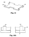
- FIG. 15 is a perspective view illustrating an assembling jig to produce battery module 20, and
- FIGS. 16 and 17 are schematic process charts illustrating the production of battery module 20.
- assembled battery 10 is an on-board battery, to be installed in vehicles such as automobiles or trains, accommodating a plurality of battery modules 20 stacked in layers. Although not illustrated, more than one of battery modules 20 are housed in a housing of the assembled battery, and an inlet-duct to introduce cooling air and an outlet duct to emit the cooling air are connected to the assembled battery housing.
- Assembled battery 10 which may be compatible with an applicable current, voltage, and capacity, is realized by the serial-parallel connection of a plurality of battery modules 20.
- the illustrated assembled battery 10 includes twelve battery modules 20 that are electrically connected in series.
- the 12 battery modules 20 shown in FIG. 1 are divided into battery module groups 20a consisting of three vertically stacked battery modules arranged in four horizontal rows.
- battery module 20 of embodiment 1 has a flat type battery 28, i.e. a unit cell, module case 23, i.e. a battery module housing (means for containing the plurality of unit cells), accommodating flat type battery 28.
- Through-bolt 31, i.e. a shaft member or securing means, is inserted through the housing, and conductive collar 42, i.e. a collar, is placed around through-bolt 31 coaxially as well as electrically connected to external terminals 51-55 or other battery modules 20.
- Collar 42 is also electrically connected to terminal 41 which is placed adjacent to conductive collar 42 and electrically connects flat type battery 28 to conductive collar 42.
- Conductive collar 42 is electrically connected to through-bolt 31 by contact with through-bolt 31. In this manner, flat type battery 28 is electrically connected to external terminals 51-55 or other battery modules 20 by contacting conductive collar 42 and through-bolt 31.
- module housing 23 includes a box-shaped first housing 24 with a prepared opening, and a second housing 25 comprising a lid body to close the opening.
- edge 25a of second housing 25 is tightened and wound around edge 24b of surrounding wall 24a of first housing 24 (see the enlarged view within FIG. 5).
- First housing 24 and second housing 25 are made of a thin steel plate or of an aluminum plate on which a predetermined shape is created with a pressing process.
- Plug slot 26 accepts a plug connector (not shown) that may detect voltage of battery module 20. Voltage detection is conducted for the purpose of managing charge and discharge of battery modules 20.
- Bolt hole 27 accepts insertion of through-bolt 31 into module housing 23.
- Bolt holes 27 are formed to be paired up between first housing 24 and second housing 25.
- Bolt holes 27 are located in four locations proximal to the four corners of module housing 23.
- Through-bolt 31 is inserted into each of three battery modules 20 in a direction parallel to battery modules 20 stacked in layers (vertical directions in FIGS. 2 and 3) through bolt hole 27.
- Through-bolt 31 is made from an electrically conductive material such as metal or metal alloy.
- Four through-bolts 31 are inserted into one battery module 20.
- the flat type battery 28 is, for example, a flat lithium-ion secondary battery in which superimposing type power generating elements (not illustrated) consisting of a cathode electrode plate, an anode electrode plate, and a separator stacked in layers.
- Flat type battery 38 is sealed by exterior material 28a, such as laminated film.
- Exterior material 28a such as laminated film.
- Flat type battery 28 will be referred to as a "battery,” hereafter.
- tabs 28t including cathode tab 28p and anode tab 28m, are plate shaped with one end electrically connected to the power generating elements. Tabs 28t are led outside of exterior material 28a. Tabs 28t extend to both sides in a longitudinal direction of battery 28.
- pressure may be applied to secure and press the power generating elements in order to maintain battery performance.
- Battery 28 is housed in module housing 23 such that the power generating elements are compressed.
- Voltage-detecting terminal board 161 is bonded over anode tab 28m.
- Voltage-detecting terminal board 161 is connected to a connector terminal to detect voltage.
- seven batteries 28 are connected in series to form a battery module 20.
- conductive collar 42 is cylindrically shaped to allow insertion of through-bolt 31.
- the diameter of the outside cylinder of collar 42 is wider near the approximate center height position than the diameter of either end of the collar.
- Conductive collar 42 is placed around through-bolt 31 coaxially by insertion of through-bolt 31.
- Conductive collar 42 is made from an electrically conductive material such as metallic materials.
- Conductive collar 42 is electrically connected to through-bolt 31 by an opening end of the conductive collar contacting the outer surface of through-bolt 31.
- One battery module 20 accommodates only one unit cell which is established by connecting more than one of the batteries. Therefore, one battery module 20 requires two conductive collars 42 for a cathode and an anode.
- Insulation collar 45 is placed around the two through-bolts 31 coaxially. As illustrated in FIG. 7C, insulation collar 45 is cylindrically shaped to allow insertion of through-bolt 31. Insulation collar 45 is made from electrically insulated materials such as resin materials or polymers. Referring to FIGS. 2 and 3 together, the positions of through-bolts 31 within conductive collars 42 are different in each battery module 20. This difference occurs in order to create a desired electrical connection between the battery modules.
- notches 42a are formed around the circumference within the inner circumference surface at an approximate center position in the axial direction.
- the axial force shown by an arrow FIG. 7A
- conductive collar 42 is pressed against terminal 41 and establishes an electrical connection with through-bolt 31.
- Conductive collar 42 is opened to be deformed while rubbing the surface of output terminal 41.
- terminal 41 is cylindrically shaped to allow insertion of through-bolt 31.
- Terminal 41 is made from electrically conductive materials such as metallic materials.
- Terminal 41 is inserted into a hollow cylindrically shaped sleeve 43, i.e. an insulation sleeve, that is made from electrically insulated materials such as resin or polymer materials.
- a hollow cylindrically shaped sleeve 43 i.e. an insulation sleeve, that is made from electrically insulated materials such as resin or polymer materials.
- module housing 23 terminal 41 can be arranged inside the module housing by arranging sleeve 43 between the upper and the bottom bolt holes 27.
- the inner circumferential surface is exposed to center hole 43 of sleeve 43a and electrode part 41a is led outside from the outer circumference surface of sleeve 43.
- Electrode part 41 a is attached to tab 28t of battery 28 by ultrasonic welding to connect terminal 41 to battery 28 electrically. By having contact with conductive collar 42, terminal 41 connects battery 28 to conductive collar 42 electrically.
- One battery module 20 requires two terminals 41, for a cathode and an anode.
- first housing 24 and second housing 25 In the upper end, or first end, and bottom end, or second end, of sleeve 43, projecting ribs 43b and 43c, or cylindrical indentations, are fitted into bolt holes 27.
- sleeve 43 a relative position between first housing 24 and second housing 25 can be determined when rim 25a of second housing 25 is wound to be tightened to rim 24b of first housing 24 by fitting each rib 43b and 43c into bolt holes 27. Therefore, in the case of assembling battery modules 20, an exclusive jig for the positioning required for determining the relative position between both housings 24 and 25 may not be needed.
- a sleeve 44 i.e. an insulation sleeve, equipped with terminal 41 (see FIG. 8B) is placed around insulation collar 45. Insulation collar 45 is placed where no electrical connection is to be established.
- Sleeve 43 equipped with a terminal 41 may be used for the purpose of commoditizing parts, even for a part in which electrical connections are not required.
- a battery module includes seven batteries 301-307 and insulation spacers 401-411 to secure tabs.
- the seven batteries are called as first battery 301 through seventh battery 307 from top to bottom along the battery layer direction (vertical direction in FIG. 9).
- spacers 401-411 are shown as broken lines.
- Cell units, within battery modules, are composed of two subassemblies, the first subassembly 81 and the second subassembly 82.
- the first subassembly 81 consists of first battery 301, second battery 302 and third battery 303 layered and connected each other in series.
- the second subassembly 82 consists of four batteries 304, 305, 306 and 307 layered and connected to each other in series.
- the first subassembly 81 has a sleeve 43 with an anode terminal 41 attached, while the second subassembly 82 has a sleeve 43 with a cathode terminal 41 attached.
- the first subassembly 81 and the second subassembly 82 are connected electrically by connecting tabs 303p and 304m to each other.
- the gap between battery 303 of the first subassembly 81 and a battery 304 of the second subassembly 82 is adhered to each other by double-sided adhesive tape. Other adhesives or attachment methods may be used as well.
- Each of spacers 401-411 is of a board shape to hold a tab from both sides of the tab along the battery layering direction, and the spacers are electrically insulative. Spacers 401-411 have an opening window to allow the tabs to be adhered to each other by ultrasonic welding. By holding tabs between spacers 401-411, tab vibration is suppressed when vibration occurs and stress is spread out from the tabs. Therefore, the durability of tabs, and also the durability of assembled batteries may be improved. In addition, because tabs are held by electrically insulative spacers 401-411, short circuits between tabs may be prevented even though a shorter distance between the batteries or tabs is present. Therefore, by minimizing the distance between the batteries, battery module size may be decreased when compared to battery modules with greater spacing between tabs.
- Electrode part 41a of an anode terminal 41 is welded to an anode tab 301m of the first battery 301 by ultrasonic welding. Electrode part 41 a of a cathode terminal 41 is welded to a cathode tab 307p of the seventh battery 307 by ultrasonic welding. In the cell unit shown in FIG. 9, the sleeves with terminals 43 are placed diagonally across the batteries.
- tab shape is determined by consideration of tab welding at subassemblies 81 and 82, tab welding between subassemblies 81 and 82, and welding between the electrode part 41a of the terminal 41 and the tab.
- the tabs connected electrically are connected by two-dot broken lines.
- Black squares next to the connection lines represent welding of tabs by ultrasonic welding at openings of spacers 401-411 in the first and the second subassemblies 81 and 82.
- White circles next to the connection lines represent welding of tabs by ultrasonic welding after assembling of the first and the second subassemblies 81 and 82.
- the electrode part 41a of the anode terminal 41 is welded to the anode tab 301m of the first battery.
- the electrode part 41a of the cathode terminal 41 is welded to the cathode tab 307p of the seventh battery.
- the order of welding of tabs is as follows: In the first subassembly 81, the cathode tab 301p of the first battery 301 is welded to the anode tab 302m of the second battery 302, then the cathode tab 302p of the second battery 302 is welded to the anode tab 303m of the third battery 303.
- the cathode tab 304p of the fourth battery 304 is welded to the anode tab 305m of the fifth battery 305. Then the cathode tab 305p of the fifth battery 305 is welded to the anode tab 306m of the sixth battery 306, and the cathode tab 306p of the sixth battery 306 is welded to the anode tab 307m of the seventh battery 307. Further, the cathode tab 303p of the third battery 303 in the first subassembly is welded to the anode tab 304m of the fourth battery 304 in the second subassembly 82.
- the layered seven batteries 301-307 are connected in series by electrically connecting opposite electrode tabs to each other, and the anode terminal 41 and cathode terminal 41 are connected to the first battery 301 and the seventh battery 307, respectively. In this manner, the anode terminal 41 and cathode terminal 41 are positioned at opposite ends of the cell unit.
- the assembled battery 10 in embodiment 1 consists of layers of more than one of battery modules 20 of the above-mentioned structure.
- two battery modules 20 next to each other are locked by a through-bolt 31 inserted into the battery modules 20.
- batteries 28 of these battery modules 20 are connected electrically through the conductive collar 42.
- the conductive collar 42 is electrically connected to the through-bolt 31 by contacting the through-bolt 31.
- the batteries 28 of these battery modules 20 are electrically connected to each other through the conductive collar 42 and the through-bolt 31.
- the four rows of battery module groups 20a are respectively referred to, from left to right, as the 1st row, 2nd row, 3rd row, and 4th row of battery module groups 20a.
- the battery module reference is made to battery modules 20 of the lowest level (L), middle level (M), and uppermost level (U).
- L lowest level
- M middle level
- U uppermost level
- an abbreviation such as 'battery module (1-U)' is used for the description.
- a cathode external terminal board 51 is located outside the battery module (1-U), whereas, an anode external terminal board 52 is located outside the battery module (4-U).
- External terminal boards 53, 54 and 55 are also located between the battery modules 20 in the uppermost level that are adjacent to each other. In other words, external terminal boards 53, 54 and 55 are located between the battery module (1-U) and the battery module (2-U), between the battery module (2-U) and the battery module (3-U), and between the battery module (3-U) and the battery module (4-U).
- Electrically conductive through-bolts 31 are inserted into the external terminal boards 51-55 to be electrically connected to the external terminal boards 51-55.
- Electrically insulative protection caps 56 are attached to the through-bolts 31 and the external terminal boards 51-55 (see FIG. 1).
- Arrow s1 connects between the cathode side external terminal board 51 and the cathode electrode tab 28p in the battery module (1-L).
- Arrow s2 connects between the anode electrode tab 28m in the battery module (1-L) and the cathode electrode tab 28p in the battery module (1-M).
- Arrow s3 connects between the anode electrode tab 28m in the battery module (1-M) and the cathode electrode tab 28p in the battery module (1-U).
- Arrow s4 connects between the anode electrode tab 28m in the battery module (1-U) and the external terminal board 53 and the cathode electrode tab 28p in the adjacent battery module (2-U).
- Arrow s5 connects between the anode electrode tab 28m in the battery module (2-U) and the cathode electrode tab 28p in the battery module (2-M).
- Arrow s6 connects between the anode electrode tab 28m in the battery module (2-M) and the cathode electrode tab 28p in the battery module (2-L).
- Arrow s7 connects between the anode electrode tab 28m in the battery module (2-L) and the external terminal board 54 and the cathode electrode tab 28p in the adjacent battery module (3-L).
- Arrow s8 connects between the anode electrode tab 28m in the battery module (3-L) and the cathode electrode tab 28p in the battery module (3-M).
- Arrow s9 connects between the anode electrode tab 28m in the battery module (3-M) and the cathode electrode tab 28p in the battery module (3-U).
- Arrow s10 connects between the anode electrode tab 28m in the battery module (3-U) and the external terminal board 55 and the cathode electrode tab 28p in the adjacent battery module (4-U).
- Arrow s11 connects between the anode electrode tab 28m in the battery module (4-U) and the cathode electrode tab 28p in the battery module (4-M).
- Arrow s12 connects between the anode electrode tab 28m in the battery module (4-M) and the cathode electrode tab 28p in the battery module (4-L).
- Arrow s13 connects between the anode electrode tab 28m in the battery module (4-L) and the anode side external terminal board 52.
- FIGS. 14A and 14B illustrate the way in which electrical connections represented by the arrow s2 or by the arrow s8 in FIG. 4 are established.
- FIG. 14A illustrates a state before more than one of battery modules 20 are locked to each other
- FIG. 14B illustrates a state in which electrical connections are established at the same time as more than one of battery modules 20 are locked to each other with a shaft member. Additional elements may be required when stacking 4 or more battery modules together in embodiment 1.
- Battery module groups 20a are mounted on bottom housing 60 which is the housing for an assembled battery.
- the bottom housing 60 is made from an electrically insulated resin material.
- nuts 32 are inserted into the screw part 31 a of the tip of a through-bolt 31 is to be screwed.
- a spring washer 33 is provided which biases the resilient force to hold down the battery module group 20a. Insulation washer 57 is placed between the external terminal boards and the through-bolts 31 (see FIGS. 2 and 3).
- FIG. 14A mount a battery module group 20a consisting of layers of three battery modules 20 on the bottom housing 60.
- a through-bolt 31 that has already passed through a spring washer 33 into each battery module 20, and then screw the screw part 31a into the nut 32.
- FIG. 14B three battery modules 20 are tightened to ensure that the stacked layers have the axial force of the through-bolt 31 applied.
- the resilient force of the compressed spring washer 33 has been biased, ensuring the stacked and layered state of the three battery modules 20 can be maintained for a long period of time.
- means to establish electrical connections consist of a terminal 41 located in the module housing 23 that is electrically connected to a battery 28, and a conductive collar 42 deformed in the direction perpendicular (horizontal directions in FIG. 14) to the axial direction (vertical directions in FIG. 14) of a through-bolt 31 by the axial force of the through-bolt 31 to get direct contact with the terminal 41.
- Both the through-bolt 31 and the conductive collar 42 are electrically conductive.
- electrical connections are established through the conductive collar 42 that is deformed by the axial force of the through-bolt 31 and is pressed against the terminal 41 and through the through-bolt 31 that is in contact with the conductive collar 42. Since the through-bolt 31 has dual functions including a function to lock more than one of battery modules 20 and a function as a bus bar to provide an electric connection, it is possible to simultaneously reduce the number of parts and the resources required for assembly.
- the lowest level and the middle level of the battery modules include parts to establish electrical connections.
- the battery module 20 of the uppermost level does not include a part to establish electrical connections.
- the terminal 41 and the anode electrode tab 28m are electrically connected, and for the battery module 20 of the middle level, the terminal 41 and the cathode electrode tab 28p are electrically connected.
- conductive collars 42 are located in the module housings 23 of the battery modules 20 of the lowest and the middle levels in which parts to establish electrical connections are included.
- an electrically insulated insulation collar 45 is present to transmit the axial force of a through-bolt 31 to the conductive collars 42.
- the insulation collar 45 is inserted into a center hole 44a of a sleeve 44 and comes in direct contact with the inner circumferential surface of the sleeve 44.
- the insulation collar 45 may be deformed by the axial force of the through-bolt 31 and may come in direct contact with the inner circumference surface of the sleeve 44.
- a sleeve 44 in a part where electrical connections are not required to be established allows the sleeve to function as an assembly part to attach the insulation collar 45.
- the arrow s2 in FIG. 4 shows that by locating a conductive collar 42, a conductive collar 42, and an insulation collar 45, in this order from the bottom, electrical connections between the battery modules 20 of the lowest level and the middle level can be established. It is the same manner to establish electrical connections represented by the arrow s6, s8 or s12 in FIG. 4. To establish electrical connections indicated by the arrow s1, s7 or s13 in FIG.
- a conductive collar 42, an insulation collar 45, and an insulation collar 45, in this order from the bottom, are used to create electrical connections between the lowest battery modules 20 and the external terminal boards 51, 54 and 52 (see FIG. 2).
- an insulation collar 45, an insulation collar 45, and a conductive collar 42, in this order from the bottom are used to create electrical connections between the battery module (1-U).
- electrical connection with the adjacent battery module (2-U) can be established through the external terminal board 53 (see FIG. 3).
- Electrical connections represented by the arrow s 10 in FIG. 4 may be completed in a similar manner.
- FIGS. 11-14 the production process of the assembled battery 10 is explained.
- a battery module group 20a in one row is described.
- four jigs 320 are inserted in four nuts 32 of bottom housing 60 of the assembled battery housing.
- Each jig 320 has a locate pin 321 to be inserted into the nut 32 and pipe part 322 to be inserted into the locate pin 321.
- the outer diameter of the pipe part 322 is smaller than the inner diameter of bolt hole 27 of the module housing 23, and the outer diameter of the locate pin is smaller than the outer diameter of through-bolt 31.
- a pipe part 322 of one jig is pulled out from the locate pin 321. Even after pulling out one pipe part 322, position of the three battery modules 20 is not changed due to the other three jigs 320.
- FIG. 13 illustrates the case in which electrical connections represented by the arrow s2 or s8 in FIG. 4 are established.
- This connection includes a conductive collar 42, a conductive collar 42 and an insulation collar 45 inserted in this order.
- a spring washer 33 is inserted as well.
- locate pin 321 is pulled out and through-bolt 31 is inserted into the insulation collar 45, the conductive collar 42 and the conductive collar 42.
- FIG. 14B when the through-bolt 31 is tightened, the axial force of the through-bolt 31 is transmitted to the conductive collars 42 through the insulation collar 45. Subsequently, the conductive collars 42 become deformed to be opened and come in direct contact with the terminal 41.
- FIGS. 15-17 production process of the battery module 20 is described.
- an assembling jig 330 attached with four locate pins 331 is used as the production process of battery module 20 is shown in FIG. 15, an assembling jig 330 attached with four locate pins 331 is used.
- the four locate pins 331 are installed at the same position as bolt holes 27 of the module housing 23.
- the outer diameter of the locate pin 331 is smaller than the inner diameter of the bolt hole 27.
- FIG. 16A four bolt holes 27 of the first housing 24 are inserted into the four locate pins 331.
- FIG. 16B a cell unit with adhesive applied on the top and bottom surfaces is set in the first housing 24.
- two sleeves 43 with terminals 41 attached and integrated into the cell unit are inserted into two locate pins 331.
- FIG. 16B two sleeves 43 equipped with terminal 41 are placed diagonally across.
- One of the two sleeves 43 equipped with terminal 41 is inserted into the locate pin 331 on the left in the FIG. 16B, and the other is inserted into the hidden locate pin 331 behind the right locate pin in the FIG. 16B. In this way, the position of the cell unit is limited in accordance with the first housing 24.
- FIG. 16C two sleeves 44 without terminals are inserted into the other two locate pins 331.
- FIG. 17A As shown in FIG. 17A, four bolt holes 27 of the second housing 25 are inserted into the four locate pins 331. As shown in FIG. 17B, the whole set along with assembly jig 330 is thrown into a tightener. By a caulking process, the edge 25a of the second housing 25 is tightened and wound around the edge 24b of the first housing 24. After this tightening procedure and pulling out the battery module 20 from the assembly jig 330, the production of the battery module 20 is completed.
- a battery module 20 in embodiment 1 has a battery 28, a module case 23 accommodating the battery 28 where a through-bolt 31 is inserted, a conductive collar 42 which are placed around the through-bolt 31 coaxially as well as electrically connected to external terminals 51-55 or other battery modules 20, and a terminal 41 which are placed around the conductive collar 42 and electrically connects the battery 28 to the conductive collar 42. Therefore, procedures to establish electrical connections in producing assembled batteries 10 can be simplified compared to the case in which each bus bar has to be tightened by bolts.
- the conductive collar 42 is electrically connected to the through-bolt 31 by contacting with the through-bolt 31.
- the battery 28 can be electrically connected to the external terminals 51-55 or other battery modules 20 by contacting with a conductive collar 42 and the through-bolt 31.
- the assembled battery 10 of embodiment 1 consists of layers of more than one battery module 20 of above-mentioned structure, two battery modules 20 next to each other are locked by a through-bolt 31 inserted into the battery modules 20, at the same time as the batteries 28 of these battery modules 20 are connected electrically through a conductive collar 42.
- Establishing electrical connections may be simplified through using through ⁇ bolt 31 to secure and electrically connect battery modules 20 in comparison to the case in which each bus bar has to be tightened by a bolt.
- the conductive collar 42 is electrically connected to the through-bolt 31 by contact with the through-bolt 31. Thereby, the batteries 28 of these battery modules 20 can be electrically connected each other through the conductive collar 42 and the through-bolt 31.
- a conductive collar 42 is cylindrically shaped to allow the insertion of a through-bolt 31.
- Conductive collar 42 is buckled by the axial force of the through-bolt 31, and is deformed in the direction perpendicular to the axial direction of the through-bolt 31. The deformation ensures contact between the terminal 41 and the conductive collar 42. Furthermore, when the conductive collar 42 is deformed, oxidized coats on the surface of the output terminal 41 are removed to reduce electrical impedance of the electrical connections.
- insulation collars 45 to transmit the axial force of the through-bolts 31 to conductive collars 42 are provided. Changing the alignment between the conductive collar 42 and the insulation collar 45 cause electrical connections in desired routes to be easily established.
- FIG. 18 is a perspective view illustrating an assembled battery 340 related to embodiment 2 of the present invention
- FIG. 19 is a cross section view along the 19-19 line in FIG. 18.
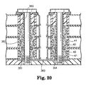
- FIG. 20 is a cross-section view along the 20-20 line in FIG. 18
- FIG. 21 is a cross section view along the 21-21 line in FIG. 18,
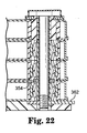
- FIG. 22 is a cross section view along the 22-22 line in FIG. 18.
- FIG. 23 is a perspective view conceptually illustrating an electrically connected state of an assembled battery 340. Common numerals are attached to the common members as those in embodiment 1 described above, and those respective descriptions are partially omitted hereafter.
- Embodiment 2 is different from embodiment 1 in that battery modules 350 are layered with more than 3 tiers, i.e., 4 tiers in embodiment 2, and the method to establish electrical connections.
- a battery module 350 in embodiment 2 has, in the same way as in the battery module 20 in Embodiment 1, a battery 28, a module case 23 accommodating the battery 28 where a through-bolt 31 is inserted, a conductive collar 42 placed around the through-bolt 31 coaxially as well as electrically connected to external terminals 51-55 or other battery modules 20, and a terminal 41 which is placed around the conductive collar 42 and electrically connects the flat type battery 28 to the conductive collar 42.
- one through-bolt 31 may support different electrical polarities. Therefore, it is required to insulate the through-bolt 31. Also, conductive collars 42 next to each other have to be insulated as well.
- the battery module 350 is equipped with a sleeve 351 placed around the through-bolt 31 coaxially and insulation 352 placed between the sleeve 351 and the through-bolt 31.
- the conductive collar 42 is electrically connected to the sleeve 351 by contacting with the sleeve 351, and the battery 28 is electrically connected to the external terminals 361-364 or other battery modules 350 through the conductive collar 42 and the sleeve 351.
- the sleeve 351 is cylindrically shaped to allow insertion of a through-bolt 31.
- the sleeve 351 is placed around the through-bolt 31 coaxially by insertion of the through-bolt 31.
- the sleeve 351 is made from electrically conductive material such as metallic materials.
- the sleeve 351 may be long enough to establish an electrical connection; there may be various lengths of sleeves 351 available to make this connection.
- Insulation sleeve 353 is also placed to keep the sleeve 351 in the position to establish electrical connection.
- the insulation sleeve 353 is cylindrically shaped so as to allow insertion of a through-bolt 31, and is made from electrically insulated materials such as resin materials. There are also various lengths of sleeves 353 available.
- the insulation 352 is cylindrically shaped to allow insertion of a through-bolt 31.
- the insulation 352 is placed to cover all length of the through-bolt 31.
- the insulation 352 is made from electrically insulated materials such as resin materials.
- an insulation ring 354 is also equipped to insulate conductive collars 42 next to each other.
- the insulation ring 354 is made from electrically insulated materials such as resin materials.
- an electrically connected state of the assembled battery 340 includes the three rows of battery module groups 350a, respectively referred to from left to right as the 1st row, 2nd row and 3rd row of battery module groups 350a, and within each battery module group 350a from bottom to top, in this order, reference is made to battery modules 350 of the lowest level (L), lower middle level (M3), upper middle level (M2), and uppermost level (U).
- L lowest level
- M3 lower middle level
- M2 upper middle level
- U uppermost level
- an abbreviation such as 'battery module (1-U)' is used for the description.
- a cathode external terminal board 361 is located outside the battery module (1-U) (see FIG. 19), whereas, an anode external terminal board 362 is located outside the battery module (3-L) (see FIG. 22).
- External terminal boards 363 and 364 are also located between the battery modules 20 in the uppermost level that are adjacent to each other. In other words, external terminal boards 363 and 364 are located between the battery module (2-U) and the battery module (3-U), and between the battery module (1-L) and the battery module (2-L) (see FIGS. 20 and 21).
- the external terminal board 363 shown in FIG. 20 is installed on the top surface of bottom housing 60 of the assembled battery housing. Electrically insulative protection caps 56 are attached to the through-bolts 31 and the external terminal boards 361 and 364.
- Arrow t1 connects between the cathode side external terminal board 351 and the cathode electrode tab 28p in the battery module (1-U).
- Arrow t2 connects between the anode electrode tab 28m in the battery module (1-U) and the cathode electrode tab 28p in the battery module (1-M3).
- Arrow t3 connects between the anode electrode tab 28m in the battery module (1-M2) and the cathode electrode tab 28p in the battery module (1-M3).
- Arrow t4 connects between the anode electrode tab 28m in the battery module (1-M3) and the external terminal board 53 and the cathode electrode tab 28p in the adjacent battery module (1-L).
- Arrows t5 and t6 connect between the anode electrode tab 28m in the battery module (1-L) and the external terminal board 363 and the cathode electrode tab 28p in the battery module (2-L).
- Arrow t7 connects between the anode electrode tab 28m in the battery module (2-L) and the cathode electrode tab 28p in the adjacent battery module (2-M).
- Arrow t8 connects between the anode electrode tab 28m in the battery module (2-M3) and the cathode electrode tab 28p in the battery module (2-M2).
- Arrow t9 connects between the anode electrode tab 28m in the battery module (2-M2) and the cathode electrode tab 28p in the battery module (2-U).
- Arrows t10 and t11 connect between the anode electrode tab 28m in the battery module (2-U) and the external terminal board 364 and the cathode electrode tab 28p in the battery module (3-U).
- Arrow t12 connect between the anode electrode tab 28m in the battery module (3-U) and the cathode electrode tab 28p in the battery module (3-M2).
- Arrow t13 connects between the anode electrode tab 28m in the battery module (3-M2) and the cathode electrode tab 28p in the battery module (3-M3).
- Arrow t14 connects between the anode electrode tab 28m in the battery module (3-M3) and the cathode electrode tab 28p in the battery module (3-L), and arrow t15 connects between the anode electrode tab 28m in the battery module (3-L) and the anode side external terminal board 362.
- FIG. 19 illustrates the manner in which electrical connection represented by the arrow t1 in FIG. 23 is established.
- the top surface of the sleeve 351 is in contact with the bottom surface of the external terminal board 361.
- the sleeve 351 is located only on the top tier of the battery module 350.
- the insulation sleeve 353 is located so as to support the sleeve 351.
- the battery module 350 is equipped with a sleeve 351 placed around the through-bolt 31 coaxially and insulation 352 placed between the sleeve 351 and the through-bolt 31.
- the conductive collar 42 can be electrically connected to the sleeve 351 by contact with the sleeve 351.
- Battery 28 is electrically connected to the external terminals 361-364 or other battery modules 350 through the conductive collar 42 and the sleeve 351. With this configuration, desired electrical connections can be established even when battery modules 350 are layered in more than four tiers, which may be beneficial in other embodiments.
- FIG. 24 is a perspective view illustrating an assembled battery 110 related to embodiment 3 of the present invention.
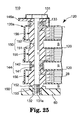
- FIG. 25 is a cross-section view along the 25-25 line in FIG. 24
- FIG. 26 is a cross section view along the 26-26 line in FIG. 24
- FIG. 27 is a cross section view along the 27-27 line in FIG. 24.
- FIG. 28 is a perspective view conceptually illustrating an electrically connected state of an assembled battery 110.
- FIG. 29 is a perspective view illustrating an example of a battery module 120 of an assembled battery 10.
- FIG. 30 is a perspective view illustrating an example of a flat type battery 28 which are accommodated in a battery module 120.
- FIG. 31A is a cross-section view illustrating insulation sleeve 155 equipped with conductive collar 142b and terminal 142a.
- FIG. 31B is a perspective view illustrating insulation sleeve 155 after removal of conductive collar 142b and terminal 142a.
- FIG. 32A is a cross-section view illustrating insulation sleeve 156 equipped with conductive collar 141b and terminal 141a
- FIG. 32B is a cross section view illustrating insulation sleeve 156 after removal of conductive collar 141b and terminal 141a.
- FIG. 33 is a cross section illustrating insulation sleeve 157 without conductive collar and terminal
- FIGS. 34A and 34B are cross-sections that show the function of the elements of the assembled battery.
- FIG. 35 is a conceptual view of the flat-type batteries and spacers in a battery module 120.
- FIG. 36 is a conceptual view of the flat-type battery in a battery module 120.
- FIGS. 37 and 38 are schematic process charts illustrating the production process of an assembled battery 110.
- FIG. 39 is a perspective view illustrating an assembling jig to produce a battery module 120.
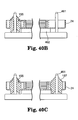
- FIGS. 40 and 41 are schematic process charts illustrating the production process of a battery module 120. Identical numerals are attached to the identical members as those in embodiment 1 described above, and the corresponding explanations are partially omitted.
- a battery module 120 in embodiment 3 has, in the same way as in the battery module 20 in embodiment 1, a battery 28, a module case 23 accommodating the battery 28 where a through-bolt 131 is inserted, a conductive collar 142b and 141b which are placed around the through-bolt 131 coaxially as well as electrically connected to external terminals 146a-146d or other battery modules 120, and a terminal 142a and 141a that is placed around the conductive collar 142b and 141b and electrically connects the flat type battery 28 to the conductive collar 142b and 141b.
- the battery module 120 is equipped with sleeves 155 and 156 placed around the through-bolt 131 coaxially.
- concavity 156a is shaped where conductive collars 142b can mate to the surface.
- inclined surface 151a is formed where collars 141b in the battery modules.
- the insulation sleeves 155 and 156 are inserted through module housing 23 and the first and second ends of said insulation sleeve 155 and 156 are extended outside of said housing 23; the first end (first spacer 151) has said inclined surfaces 155a and 156a, and the second end (the second spacer 152) is shaped into a tapered surface.
- Embodiment 3 is different from the assembled battery 10 in embodiment 1 in that an electrically insulated connection part 150 is provided, resulting in more than one of battery modules 120 stacked in layers with intervening spaces S there between.
- the through-bolt 131 is inserted into each of three battery modules 120 in a direction parallel to the battery modules 120 stacked in layers (vertical directions in FIGS. 25) through a through-bolt hole 27.
- the through-bolt 131 is not used as a member to establish electrical connections. Therefore, the material of the through-bolt 131 may be either electrically conductive or electrically insulated.
- the battery module groups 120a are mounted on a bottom housing 60.
- the bottom housing 60 is made from an electrically insulated resin material.
- nuts 132 into which the screw part 31a of the tip of a through-bolt 131 is to be screwed, are inserted.
- a spring 133 is provided between the head of the through-bolt 131 and the battery module 120 of the uppermost level to provide a bias force to hold down the battery module group 120a.
- Connection part 150 includes a first spacer 151 on the first end protruding from a module housing 23 in the direction of the letter 1 (upward direction in FIG. 25) parallel to the stacking and layering direction, a second spacer 152 on the second end protruding from the module housing 23 in the opposite direction (downward direction in FIG. 25) parallel to the stacking and layering direction, and a housing side spacer 153 protruding from the bottom housing 60 toward a battery module group 120a.
- the first and second spacers 151 and 152 together with a hollow cylindrically shaped sleeve body 154, comprise a sleeve 155, 156 and 157 (see FIGS. 31-33).
- the first spacer 151 is integrally formed at the upper edge of the sleeve body 154.
- the second spacer 152 is integrally formed at the lower edge of the sleeve body 154.
- the first spacer 151 protrudes from a bolt hole 27 formed in a first housing 24, and the second spacer 152 protrudes from a bolt hole 27 formed in the second housing 25.
- the sleeve 155, 156 and 157 are made from electrically insulated materials such as resin materials.
- the first spacer 151 is provided with a tapered dent into which the tip of the tapered second spacer 152 is fitted, and engages with the second spacer 152 by the projections and recesses. Both the first and second spacers 151 and 152 have an inclined surface which directly contacts the other, 151a and 152a, respectively. As the first spacer 151 engages with the second spacer 152 by projections and recesses, accordingly, paired battery modules 120 adjacent to each other and parallel to the stacking and layering direction are stacked in layers with an intervening space S there between.
- the housing side spacer 153 is also provided with a tapered dent into which the tip of the tapered surface of second spacer 152 is fitted and engages with the second spacer 152 by the projections and recesses. Both the housing side spacer 153 and the second spacer 152 have an inclined surface directly contacting the other, 153a and 152a, respectively. As the housing side spacer 153 engages with the second spacer 152 by projections and recesses, accordingly, the battery modules 120 of the lowest level and the bottom housing 60 are stacked in layers with an intervening space S there between.
- connection parts 150 (between the first spacer 151 and the second spacer 152, or the housing side spacer 153 and the second spacer 152) are connected to each other through inclined surfaces 151a, 152a, and 153a, thus allowing positioning between the connection parts 150 to be easily conducted, and as a result, the positioning between paired battery modules 120 adjacent to each other parallel to the stacking and layering direction and between battery modules 120 of the lowest level and the bottom housing 60 can be easily conducted.
- Each space S is used as a cooling air passage for cooling air in order to flow down to cool each battery module 120.
- Electrical connecting means consists of output terminals 144 located in the connection parts 150. By connecting the connection parts 150 to each other by the axial force of through-bolts 131, electrical connections are established through the output terminals 144 that are pressed against each other. Since a bus bar function to establish electrical connections is integrated to the connection parts 150 by which a space S is created, the number of parts can be reduced while reducing the resources required for assembly.
- Each output terminal 144 is located on the inclined surfaces 151a, 152a, and 153a of the connection parts 150. More specifically, an output terminal 144 includes a first output terminal 141 to be located on the inclined surface 151a of the first spacer 151, a second output terminal 142 to be located on the inclined surface 152a of the second spacer 152, and a housing side output terminal 143 to be located on the inclined surface 153a of the housing side spacer 153. Each output terminal 144 is made from electrically conductive material such as metallic materials.
- the second output terminal 142 has a plate 142b that works as a conductive collar placed on the inclined surface 152a of the second spacer 152 of the insulation sleeve 155.
- a terminal board 142a which is equivalent to a terminal, is connected integrally to the plate 142b.
- the plate 142b is shaped to match the shape of the second spacer 152 and is attached to the second spacer 152 with an electrically insulated retaining ring 145.
- the terminal board 142a extends into the module housing 23, connecting to a tab of the battery 28.
- the surface of the second output terminal 142 is exposed onto the inclined surface 152a.
- the first output terminal 141 has a plate 141b that works as a conductive collar placed on the inclined surface 151a of the first spacer 151 of the insulation sleeve 156.
- a terminal board 141a which is equivalent to a terminal, is connected integrally to the plate 141b.
- the plate 141b is shaped which matches the shape of the first spacer 151, and is attached to the first spacer 151 with an electrically insulated retaining ring 145b.
- the terminal board 141a extends into the module housing 23, connecting to a tab of the battery 28.
- the surface of the first output terminal 141 is exposed onto the inclined surface 151a.
- the housing side output terminal 143 is inserted into the housing side spacer 153.
- the surface of the housing side output terminal 143 is exposed onto the inclined surface 153a.
- a cell unit in a battery module includes eight batteries 421-428 and insulation spacers 431-458 to secure tabs.
- the eight batteries are referred to as the first battery 421 through the eighth battery 428 from top to bottom along battery layer direction (vertical direction in FIG. 35).
- spacers 431-458 are shown as broken lines.
- Cell units are composed of three subassemblies; the first subassembly 81, the second subassembly 82 and the third subassembly 83.
- the first subassembly 81 consists of three batteries 421, 422 and 423 layered and connected to each other in series.
- the second subassembly 82 consists of two batteries 424 and 425 layered and connected to each other in series.
- the third subassembly 83 consists of three batteries 426, 427 and 428 layered and connected to each other in series.
- the first subassembly 81 has a terminal 142a integrated in the anode conductive collar 142b
- the third subassembly 83 has a terminal 141a integrated in the cathode conductive collar 141b.
- the first subassembly 81 and the second subassembly 82 are connected electrically by connecting tabs 423p and 424m to each other facing outside of the spacers.
- the second subassembly 82 and the third subassembly 3 are also connected electrically by connecting tabs 425p and 426m to each other facing outside of the spacers.
- the gap between a battery 423 of the first subassembly 81 and a battery 424 of the second subassembly 82, and between a battery 425 of the second subassembly 82 and a battery 426 of the third subassembly 83, are adhered to each other by double-sided adhesive tape.
- Each of spacers 431-458 has a board shape to hold a tab from both sides of the tab along the battery layering direction, and is electrically insulative. Spacers 431-458 have an opening window so as to bond the held tabs to each other by ultrasonic welding.
- the anode terminal 142a is bonded to anode tab 301m of the first battery 301 by ultrasonic welding.
- the cathode terminal 141 a is bonded to cathode tab 428p of the eighth battery 428 by ultrasonic welding.
- terminals are placed on the same edge in the lengthwise direction.
- the tab shape is determined to facilitate tab bonding at subassemblies 81, 82 and 83, tab bonding between subassemblies 81, 82 and 83, and bonding between the terminals 141a and 142a and the tabs.
- the tabs connected electrically are connected by two-dot broken lines.
- "Black squares” next to the connection lines represent bonding of tabs by ultrasonic welding at openings of spacers 431-458 in the first, the second and the third subassemblies 81, 82 and 83.
- “Black circles” next to the connection lines represent bonding of tabs which are facing outside by ultrasonic welding outside of spacers 431-458 in the first and the third subassemblies 81 and 83.
- the anode terminal 142a is welded to the anode tab 421m of the first battery 421, and the cathode terminal 141a is welded to the cathode tab 427p of the seventh battery 427.
- the order of welding of tabs starts in the first subassembly 81, where the cathode tab 421p of the first battery 421 is welded to the anode tab 422m of the second battery 422. Then the cathode tab 422p of the second battery 422 is welded to the anode tab 423m of the third battery 423.
- the cathode tab 424p of the fourth battery 424 is welded to the anode tab 425m of the fifth battery 425.
- the cathode tab 427p of the seventh battery 427 is welded to the anode tab 428m of the eighth battery 428, and then the cathode tab 426p of the sixth battery 426 is welded to the anode tab 427m of the seventh battery 427.
- the cathode tab 425p of the fifth battery 425 in the second subassembly is welded to the anode tab 426m of the sixth battery 426 in the third subassembly 83.
- the layered eight batteries 421-428 are connected in series by electrically connecting opposite electrode tabs to each other, and the anode terminal 142a and cathode terminal 141a are connected to the first battery 421 and the eighth battery 428, respectively, which are positioned at the each end along the layering direction.
- the assembled battery 110 in embodiment 3 is comprised of more than one of battery modules 120 of above-mentioned structure. Briefly, in the assembled battery 110, two battery modules 120 next to each other are locked by a through-bolt 131 inserted into the battery modules 120, while the insulation sleeves 155 and 156 of each battery module 120 are in contact with each other. At the same time, the batteries 28 of these battery modules 120 are connected electrically through conductive collars 142b and 141b. The insulation sleeves 155 and 156 are inserted through module housing 23 and the both ends of the insulation sleeve 155 and 156 are extended outside of the module housing 23.
- One projection of the first end has the concavity 155a and 156a, and the other projection at the second end (the second spacer 152) is shaped into a tapered shape.
- the concavity 156a of the insulation sleeve 156 on one battery module 120 out of two battery modules is engaged with the tapered projection (the second spacer 152) of the insulation sleeve 155 on the other battery module 120.
- Arrows u1-u13 in FIG. 28 each conceptually represent an electrically connected status established in the assembled battery 110.
- Arrow u1 connects between the cathode side external terminal board 146a and the cathode electrode tab 28p in the battery module (1-U).
- Arrow u2 connects between the anode electrode tab 28m in the battery module (1-U) and the cathode electrode tab 28p in the battery module (1-M).
- Arrow u3 connects between the anode electrode tab 28m in the battery module (1-M) and the cathode electrode tab 28p in the battery module (1-L).
- Arrow u4 connects between the anode electrode tab 28m in the battery module (1-L) and the external terminal board 146d and the cathode electrode tab 28p in the adjacent battery module (2-L).
- Arrow u5 connects between the anode electrode tab 28m in the battery module (2-L) and the cathode electrode tab 28p in the battery module (2-M).
- Arrow u6 connects between the anode electrode tab 28m in the battery module (2-M) and the cathode electrode tab 28p in the battery module (2-U).
- Arrow u7 connects between the anode electrode tab 28m in the battery module (2-U) and the external terminal board 146b and the cathode electrode tab 28p in the adjacent battery module (3-U).
- Arrow u8 connects between the anode electrode tab 28m in the battery module (3-U) and the cathode electrode tab 28p in the battery module (3-M).
- Arrow u9 connects between the anode electrode tab 28m in the battery module (3-M) and the cathode electrode tab 28p in the battery module (3-L).
- Arrow u10 connects between the anode electrode tab 28m in the battery module (3-L) and the external terminal board 146e and the cathode electrode tab 28p in the adjacent battery module (4-L).
- Arrow u11 connects between the anode electrode tab 28m in the battery module (4-L) and the cathode electrode tab 28p in the battery module (4-M).
- Arrow u12 connects between the anode electrode tab 28m in the battery module (4-M) and the cathode electrode tab 28p in the battery module (4-U), and arrow u13 connects between the anode electrode tab 28m in the battery module (4-U) and the anode side external terminal board 146e.
- FIG. 25 represents a state in which electrical connections between the uppermost level battery modules 120 and the positive side external terminal board 146a and between paired battery modules 120 of the lowest level and middle level the battery modules 120 are established.
- the cathode side external terminal board 146a is in contact with a plate 141b placed on the inclined surface 151a of the first spacer 151 of the insulation sleeve 156.
- the plate 141b is connected electrically to the cathode tab 28p of the battery 28 of the uppermost battery module 120 through the terminal board 141a.
- the plate 142b placed on the inclined surface 152a of the second spacer 152 of the insulation sleeve 155 is connected electrically to the cathode tab 28p of the battery 28 of the middle battery module 120 through the terminal board 142a.
- the plate 141b placed on the inclined surface 151a of the first spacer 151 of the insulation sleeve 156 is connected electrically to the cathode tab 28p of the battery 28 of the lowest battery module 120 through the terminal board 141a.
- the external terminal board 146d is insert-molded on the bottom housing 60 to electrically connect the housing side output terminal 143 next to each other.
- Each output terminal 144 is located on an inclined surface directly contacting the other surface 151a, 152a, and 153a, respectively. Therefore, as indicated by arrow f in FIG. 34B, the axial force of the through-bolt 131 provides the force to the output terminals 144 (the first output terminal 141 and the external terminals, the first output terminal 141 and the second output terminal 142, the second output terminal 142 and the housing side output terminal 143), thus ensuring the electrical connections between the output terminals 144. Moreover, by increasing the contact area between the output terminals 144, electrical resistance may be reduced.
- an exclusive insulation sleeve 157 of FIG. 33 without an output terminal 144 equipped is placed where electrical connections are not established.
- insulation sleeves 155 and 156 equipped with an output terminal 144 when electrical connections are not required are not required.
- a battery module group 120a in one row is described.
- the first spacer 151 engages with the second spacer 152 with projections and recesses such that more than one of the battery modules 120 can be stacked in layers while determining the position without any exclusive jigs or other mounting devices.
- the housing side spacer 153 engages with the second spacer 152 by projections and recesses to position the lowest battery module 120.
- the first spacer 151 of the lowest battery module 120 engages with the second spacer 152 by projections and recesses, accordingly, to position the middle battery module 120.
- the first spacer 151 of the middle battery module 120 engages with the second spacer 152 by projections and recesses to position the uppermost battery module 120.
- through-bolts 131 are inserted into each insulation sleeve 155 and 156.
- the production process of battery module 120 includes the use of an assembling jig 461 attached with four locate pins 460.
- the four locate pins 461 are installed at the same position as bolt holes 27 of the module housing 23.
- the outer diameter of the locate pin 461 is somewhat smaller than the inner diameter of the bolt hole 27.
- a protruded receptacle 462 is formed to hold the first housing 24 on the base plate of the assembly jig.
- FIG. 40A four bolt holes 27 of the first housing 24 are inserted into the four locate pins 461.
- FIG. 40B a cell unit with adhesive applied on the top and bottom surfaces is set in the first housing 24.
- two insulation sleeves 155 and 156 equipped with terminals which are integrated into the cell unit are inserted into two locate pins 461.
- One of the two insulation sleeves 155 and 156 equipped with a terminal is inserted into the locate pin 461 on the left front in the FIG. 40B, and the other is inserted into the hidden locate pin 461 behind the right locate pin in the FIG. 40B.
- the sleeve body 154 and the retaining rings 145 and 145b are welded beforehand.
- FIG. 40C two insulation sleeves 157 without terminals are inserted into the remaining two locate pins 461.
- FIG. 41A As shown in FIG. 41A, four bolt holes 27 of the second housing 25 are inserted into the four locate pins 461. As shown in FIG. 41B, the whole set along with assembly jig 460 is thrown into a tightener. Through a caulking process, the edge 25a of the second housing 25 is tightened and wound around the edge 24b of the first housing 24. After this tightening procedure and pulling the battery module 120 out from the assembly jig 460, the production of the battery module 120 is completed.
- the battery module 120 is equipped with sleeves 155 and 156 placed around the through-bolt 131 coaxially.
- concavity 156a is shaped where conductive collars 142b can fit into, and in the inner wall of said concavity 156a, a slope 151a is formed where collars 141b in the battery modules. In this way, battery modules 120 can be electrically connected easily each other.
- the insulation sleeves 155 and 156 are inserted through module housing 23 and the both ends, first and second ends, of said insulation sleeve 155 and 156 are extended outside of said housing 23.
- the first end has said concave shaped 155a and 156a, and the second end is shaped into a tapered shape. Since electrical connections are established through conductive collars 142b and 141b pressed against each other, secure electrical connections can be established by ensuring contact between the conductive collars 142b and 141b.
- the assembled battery 110 in embodiment 3 consists of layers of more than one of battery modules 120 of above-mentioned structure.
- Two battery modules 120 next to each other are locked by a through-bolt 31 inserted into the battery modules 120, while the insulation sleeves 155 and 156 of each battery module 120 are in contact each other.
- the batteries 28 of these battery modules 120 are connected electrically through a conductive collar 142b and 141b.
- connection part 150 has an inclined surface directly contacting the other surfaces 151a, 152a, and 153a, respectively. Since output terminals 144 are located on the inclined surfaces 151a, 152a, and 153a, the contact between the output terminals 144 may becomes more secure.
- a through-bolt 131 is not a member to establish electrical connections.
- through-bolt 131 is used to secure the state in which battery modules 120 are stacked in layers, and at the same time provide the bias force to ensure electrical connecting means.
- the through-bolt 131 can be installed in locations different from the connection parts 150.
- FIGS. 42A and 42B are drawings illustrating the operations of a connection part 250 of an assembled battery related to embodiment 4 of the present invention.
- the identical codes are used to explain the identical members as those in embodiment 3.
- the assembled battery in embodiment 4 in the same way as the assembled battery 110 in embodiment 3, is provided with electrically insulated connection parts 250 to stack a plurality of battery modules 120 in layers with intervening spaces S there between.
- the assembled battery in embodiment 3 is different from assembled batteries 10, 340 and 110 in embodiments 1-3, respectively, in that the securing means applies force to ensure the state of being stacked in layers by the engaging force of the engagement.
- a connection part 250 in the same way as those in embodiment 3, includes a first spacer 251 protruding from a module housing 23 in the direction of the letter 1 (upward direction in FIG. 42) parallel to the stacking and layering direction, and a second spacer 252 protruding from a module housing 23 in the opposite direction (downward direction in FIG. 42) parallel to the stacking and layering direction.
- first spacer 251 engages with the second spacer 252 by projections and recesses, accordingly, paired battery modules 120 adjacent to each other and parallel to the stacking and layering direction are stacked in layers with an intervening space S there between.
- the first spacer 251 is provided with a dent into which the tip of the second spacer 252 is fitted, and engages with the second spacer 252 by the projections and recesses.
- the first and second spacers 251 and 252, respectively, include engaging parts 25 1 a, and 252a, respectively, to be engaged to each other with shaft member 253.
- the engaging parts 251a and 252a being equivalents of securing means 230, the engaging force of the engagement of both applies force to ensure the state of being stacked in layers.
- the engaging part 252a of the second spacer includes a tongue 252b extending downward, reducing the diameter, and a projection 252c protruding towards the outside in a radial direction is formed at the bottom end of the tongue 252b.
- a slit is formed on the tongue 252b in an appropriate position as necessary and is made such that it can be opened freely towards the outside in a radial direction.
- the engaging part 251a of the first spacer 251 includes an inclined surface 251b reducing the diameter in the downward direction. At the end of the inclined surface 251b in the FIG., a recess 251c (equivalent to concave ring) is formed for the projection 252c fit into.
- the tongue 252b opens toward the outside in a radial direction, and the projection 252c fits into the recess 251c. Thereby, engaging force is generated by the engagement, and force ensuring the state in which battery modules 120 are stacked in layers is applied.
- the rod 253 in embodiment 4 is neither a member to establish electrical connections nor a member to apply axial force to tighten the plurality of battery modules 120 stacked in layers, but merely a member to open the tongue 252b. Therefore, the rod 253 may be any that can be inserted or pressed into the center holes 251 d, and 252d.
- the end of the rod 253 may be screwed into the bottom housing 60.
- the rod 253 may not apply axial force to tighten the plurality of battery modules 120 stacked in layers. In some cases, some axial force may not be avoidable when securing rod 253.
- Electrical connecting means consists of output terminals 244 located in the connection parts 250.
- the output terminal 244 includes a first output terminal 241 to be located on the inclined surface 251b of the first spacer 251 and a second output terminal 242 to be located on the outer circumference surface of the tongue 252b of the second spacer 252.
- Each output terminal 244 is made from electrically conductive material such as metallic materials. Although the illustration is omitted, each output terminal 244 is electrically connected to electrode tabs 28t of a battery 28 of paired battery modules 120.
- a housing side spacer that is the same as first spacer 251 is provided on the bottom housing 60, and is configured so as to be able to establish electrical connections between a battery module 120 and an external terminal board.
- electrical connection establishment may be simplified when compared to the case in which each bus bar has to be tightened by bolts.
- the resulting contact force between the output terminals 244 may be equalized, regardless of the connecting locations.
Landscapes
- Engineering & Computer Science (AREA)
- General Chemical & Material Sciences (AREA)
- Chemical & Material Sciences (AREA)
- Chemical Kinetics & Catalysis (AREA)
- Electrochemistry (AREA)
- Power Engineering (AREA)
- Transportation (AREA)
- Mechanical Engineering (AREA)
- Life Sciences & Earth Sciences (AREA)
- Sustainable Development (AREA)
- Sustainable Energy (AREA)
- Manufacturing & Machinery (AREA)
- Connection Of Batteries Or Terminals (AREA)
- Battery Mounting, Suspending (AREA)
Abstract
Description
- The present invention relates to a battery and particularly, but not exclusively, to a battery module, to an assembled battery and to a method of assembly thereof.
- High output and high capacity assembled batteries are typically produced by arranging and electrically connecting more than one battery module in series and/or in parallel. More than one electrically conductive bus bars are locked to electrode terminals by bolts in order to electrically connect the electrode terminals of the battery modules of an assembled battery. Each of the battery modules includes one or more unit cells, where the unit cells are electrically connected within a housing of the battery module. Battery modules may be placed next to each other and also stacked in layers to produce one assembled battery. These assembled batteries may be used in individual or commercial applications such as motor vehicles including airplanes, automobiles, and marine vehicles.
- In general, the invention directed to an assembled battery that includes a plurality of battery modules and unit cells. The unit cells of each battery module are electrically connected to each other, to external terminals, and other battery modules through a plurality of collars placed around a shaft member that secures the battery modules. The shaft member may electrically connect the unit cells in some embodiments, and a sleeve may insulate the collars from the shaft in embodiments where electrical connections do not include the shaft member. Axial force from the securing shaft member deforms the collars to create the electrical connections. Alternative embodiments include engagement members secure the battery modules in order to eliminate the need for axial force from a shaft member to complete the assembled battery.
- Securing or tightening each bus bar to the electrode terminals by bolts of an assembled battery increases system complexity and requires more time during manufacturing.
- It is an aim of the invention to address this problem. Embodiments of the invention provide a battery module and a battery which may permit simplified operations to establish secure electrical connections. Other aims and advantages of the invention will become apparent from the following description, claims and drawings.
- Aspects of the invention therefore provide a battery module, a battery and a method as set out in the appended claims.
- According to another aspect of the invention there is provided a battery module comprising a housing containing a plurality of unit cells having electrical terminals, a shaft member inserted through the housing; and a collar placed around the shaft member, wherein the collar is electrically connected to at least one of the electrical terminals of the unit cells.
- In one embodiment the collar is electrically connected to an external terminal of the battery module for electrical connection to a second battery module.
- In one embodiment the collar is electrically connected to the shaft member by contact, and wherein the plurality of unit cells are electrically connected to the external terminal and the second battery module through the collar and the shaft member.
- The battery module may comprise an insulation sleeve positioned coaxially around the shaft member, wherein the collar is electrically connected to the insulation sleeve by contact. The unit cells may be electrically connected to at least one of the external terminal and the second battery module through the collar and the insulation sleeve.
- In one embodiment a first end of the insulation sleeve forms a cylindrical indentation in an outer wall that fits into the collar, and wherein the first end of the insulation sleeve forms an inclined surface of an inner wall opposite of the outer wall.
- In one embodiment both ends of the insulation sleeve extend outside of the housing, and wherein the second end of the insulation sleeve comprises a tapered surface.
- According to another aspect of the invention there is provided an assembled battery comprising a plurality of battery modules, each battery module comprising a housing containing a plurality of unit cells having electrical terminals, a shaft member inserted through the housing and a collar placed around the shaft member, wherein the collar is electrically connected to at least one of the electrical terminals of the unit cells.
- In one embodiment the collar is electrically connected to an external terminal of the battery module for electrical connection to a second battery module.
- In one embodiment the plurality of battery modules are electrically connected through external terminals of each of the plurality of battery modules.
- In one embodiment the shaft member locks the first battery module and a second battery module together and electrically connects the first and second battery modules through the collar of each battery module.
- The battery may comprise at least one engagement member that locks the first battery module to the second battery module when contacted by the shaft.
- In one embodiment each of the plurality of battery modules comprises an insulation sleeve positioned coaxially around the shaft member, wherein the collar is electrically connected to the insulation sleeve by contact. The unit cells of a first battery module may be electrically connected to at least one of the external terminal and the second battery module through the collar and the insulation sleeve. The first and second battery modules may be electrically connected through the collar and the insulation sleeve of each battery module.
- In one embodiment a first end of each of the insulation sleeve forms a cylindrical indentation of an outer wall that fits into the collar. The first end of the insulation sleeve may form an inclined surface on an inner wall opposite of the outer wall. The insulation sleeve of a first battery module may fit into the collar of a second battery module.
- In one embodiment the first end and a second end of the insulation sleeve extends outside of the housing. The second end of the insulation sleeve may comprise a tapered surface. The first end of the insulation sleeve of the second battery module may accept the second end of the insulation sleeve of the first battery module.
- The battery may comprise a tapered ring that contacts the inclined surface of the insulation sleeve of the second battery module, wherein the second end of the insulation sleeve of the first battery module contacts an inner surface of the tapered ring.
- According to yet another aspect of the invention there is provided a method for assembly of a battery module comprising stacking a plurality of unit cells within a housing to place a plurality of terminals of the unit cells adjacent to a plurality of collars located within the first housing, wherein at least one of the plurality of collars electrically connects the terminals of the unit cells to an external terminal for electrical connecting a second battery module and inserting a shaft member through the housing and the plurality of collars.
- The method may comprise electrically connecting the plurality of collars to the shaft member, wherein the plurality of collars are electrically connected to at least one of the electrical terminals of the unit cells and to an external terminal of the battery module for electrical connection to the second battery module.
- The method may comprise deforming at least one of the plurality of collars with force from the inserted shaft member to electrically connect at least one of the plurality of terminals to the deformed collar.
- The method may comprise g inserting a plurality of insulation sleeves around the shaft member and between the plurality of collars, wherein the unit cells are electrically connected to the external terminal and the second battery module through the plurality of collars and the plurality of insulation sleeves.
- The method may comprise mating one of the plurality of collars around a first end of a second insulation sleeve, wherein the first end forms a cylindrical indentation of an outer wall.
- The method may comprise mating a tapered second end of a first insulation sleeve to an inclined surface of an inner wall of the first end of the second insulation sleeve.
- The method may comprise stacking a first battery module on top of the second battery module, wherein the first battery module comprises at least one of the plurality of unit cells and the first housing, wherein and the second battery module comprises at least one of the plurality of unit cells and a second housing and locking the first and second battery modules together with the shaft member.
- In one embodiment the shaft member electrically couples the first and second battery modules together through the plurality of collars.
- The method may comprise deforming at least one of the plurality of collars to electrically connect the first battery module and second battery module through at least the deformed collar and the plurality of insulation sleeves.
- The method may comprise inserting a tapered ring between the insulation sleeve of the first battery module and the insulation sleeve of the second battery module, wherein the tapered ring contacts the inclined surface of the insulation sleeve of the second battery module, and wherein the second end of the insulation sleeve of the first battery module contacts an inner surface of the tapered ring.
- In one embodiment locking the first and second battery modules together comprises mating at least one engagement part with the force of the shaft member.
- According to a further aspect of the invention there is provided a battery module comprising a plurality of unit cells having electrical terminals, means for containing the plurality of unit cells, means for electrically connecting at least one of the plurality of unit cells to an external terminal and means for securing the electrically coupling means.
- In an embodiment a battery module includes a housing containing a plurality of unit cells having electrical terminals, a shaft member inserted through the housing, and a collar placed around the shaft member, wherein the collar is electrically connected to at least one of the electrical terminals of the unit cells.
- In an embodiment an assembled battery includes a plurality of battery modules. Each battery module includes a housing containing a plurality of unit cells having electrical terminals, a shaft member inserted through the housing, and a collar placed around the shaft member, wherein the collar is electrically connected to at least one of the electrical terminals of the unit cells.
- In an embodiment, a method for assembly of a battery module includes stacking a plurality of unit cells within a housing to place a plurality of terminals of the unit cells adjacent to a plurality of collars located within the first housing, wherein at least one of the plurality of collars electrically connects the terminals of the unit cells to an external terminal for electrical connecting a second battery module, and inserting a shaft member through the housing and the plurality of collars.
- In an embodiment, a battery module includes a plurality of unit cells having electrical terminals, means for containing the plurality of unit cells, means for electrically connecting at least one of the plurality of unit cells to an external terminal, and means for securing the electrically coupling means.
- The invention may provide one or more advantages. Electrically connecting unit cells with collars may facilitate battery assembly, and utilizing deformable collars may allow the connections to be made during the securing of the shaft member. Additionally, the shaft member may be electrically insulated from the collars to allow a greater number of stacked battery modules. Further, engagement parts may be employed to eliminate the need for the shaft member to provide axial force for securing the battery modules.
- Moreover, oxidation film may be removed from unit cell terminals during the deformation of collars when the shaft member is secured. Removing any oxidation may reduce impedance to current flow in the electrical connections.
- The various aspects, embodiments and alternatives set out in the preceding paragraphs, in the claims and in the following description may be implemented individually or in combination.
- The present invention will now be described, by way of example only, with reference to the accompanying drawings in which:
- FIG. 1 is a perspective view illustrating a first form of assembled battery embodying the invention.
- FIG. 2 is a cross section view along the 2-2 line in FIG. 1.
- FIG. 3 is a cross section view along the 3-3 line in FIG. 1.
- FIG. 4 is a perspective view conceptually illustrating an electrically connected state of an assembled battery.
- FIG. 5 is a perspective view illustrating one example of a battery module of an assembled battery.
- FIG. 6 is a perspective view illustrating one example of a flat type battery, or unit cell, within a battery module.
- FIGS. 7A and 7B are cross section drawings of a conductive collar opened to be deformed as shown in FIGS. 2 and 3.
- FIG. 7C is a cross section of the insulation collar shown in FIGS. 2 and 3.
- FIGS. 8A and 8B are partially broken perspective views of the sleeve shown in FIGS. 2 and 3.
- FIG. 9 is a conceptual view of layering the flat-type batteries and spacers in a battery module.
- FIG. 10 is a conceptual view of electrical connection conditions of the flat-type batteries in a battery module.
- FIGS. 11-14 are schematic process charts illustrating the production of an assembled battery.
- FIG. 15 is a perspective view illustrating an assembling jig to produce a battery module.
- FIGS. 16-17 are schematic process charts illustrating the production of a battery module.
- FIG. 18 is a perspective view illustrating a second form of assembled battery embodying the invention.
- FIG. 19 is a cross section view along the 19-19 line in FIG. 18.
- FIG. 20 is a cross section view along the 20-20 line in FIG. 18.
- FIG. 21 is a cross section view along the 21-21 line in FIG. 18.
- FIG. 22 is a cross section view along the 22-22 line in FIG. 18.
- FIG. 23 is a perspective view conceptually illustrating an electrically connected state of an assembled battery.
- FIG. 24 is a perspective view illustrating a third form of assembled battery embodying the invention.
- FIG. 25 is a cross section view along the 25-25 line in FIG. 24.
- FIG. 26 is a cross section view along the 26-26 line in FIG. 24.
- FIG. 27 is a cross section view along the 27-27 line in FIG. 24.
- FIG. 28 is a perspective view conceptually illustrating an electrically connected state of an assembled battery.
- FIG. 29 is a perspective view illustrating one example of a battery module of an assembled battery.
- FIG. 30 is a perspective view illustrating one example of a flat type battery of a battery module.
- FIG. 31A is a cross-section drawing illustrating an insulation sleeve equipped with a conductive collar and a terminal.
- FIG. 31B is a perspective view illustrating the insulation sleeve after removal of the conductive collar and the terminal.
- FIG. 32A is a cross section drawing illustrating an insulation sleeve equipped with a conductive collar and a terminal.
- FIG. 32B is a perspective view illustrating the insulation sleeve after removal of the conductive collar and the terminal.
- FIG. 33 is a cross section illustrating the insulation sleeve without the conductive collar and terminal.
- FIGS. 34A and 34B are cross-section illustration of battery module assembly.
- FIG. 35 is a conceptual view of layering the flat-type batteries and spacers in a battery module.
- FIG. 36 is a conceptual view of electrical connections of the flat-type batteries in a battery module.
- FIGS. 37-38 are schematic process charts illustrating the production of an assembled battery.
- FIG. 39 is a perspective view illustrating an assembling jig to produce a battery module.
- FIGS. 40-41 are schematic process charts illustrating the production of a battery module.
- FIGS. 42A and 42B are illustrations of a connection part of a fourth form of assembled battery embodying the invention.
- FIG. 1 is a perspective view illustrating an assembled
battery 10 related toembodiment 1 of the present invention. FIGS. 2-17 are also related toembodiment 1. FIG. 2 is a cross-section view along the 2-2 line in FIG. 1. FIG. 3 is a cross-section view along the 3-3 line in FIG. 1. FIG. 4 is a perspective view conceptually illustrating an electrically connected state of an assembledbattery 10, and FIG. 5 is a perspective view illustrating anbattery module 20 that of assembledbattery 10. FIG. 6 is a perspective view illustrating an example offlat type battery 28 which is accommodated inbattery module 20. FIGS. 7A and B are cross-section drawings ofconductive collar 42, i.e. a deformation member, opened to be deformed as shown in FIGS. 2 and 3. The collar may also be an electrically connecting means. FIG. 7C is a cross-section view ofinsulation collar 45 as shown in FIGS. 2 and 3. FIGS. 8A and B are partially broken perspective views ofsleeves battery module 20. FIG. 10 is a conceptual view illustrating the electrical connection of flat type batteries inbattery module 20. FIGS. 11-14 are schematic process charts illustrating the production of assembledbattery 10. FIG. 15 is a perspective view illustrating an assembling jig to producebattery module 20, and FIGS. 16 and 17 are schematic process charts illustrating the production ofbattery module 20. - Referring to FIG. 1, assembled
battery 10 is an on-board battery, to be installed in vehicles such as automobiles or trains, accommodating a plurality ofbattery modules 20 stacked in layers. Although not illustrated, more than one ofbattery modules 20 are housed in a housing of the assembled battery, and an inlet-duct to introduce cooling air and an outlet duct to emit the cooling air are connected to the assembled battery housing. -
Assembled battery 10, which may be compatible with an applicable current, voltage, and capacity, is realized by the serial-parallel connection of a plurality ofbattery modules 20. The illustrated assembledbattery 10 includes twelvebattery modules 20 that are electrically connected in series. The 12battery modules 20 shown in FIG. 1 are divided intobattery module groups 20a consisting of three vertically stacked battery modules arranged in four horizontal rows. - Briefly, referring to FIGS. 2 and 3,
battery module 20 ofembodiment 1 has aflat type battery 28, i.e. a unit cell,module case 23, i.e. a battery module housing (means for containing the plurality of unit cells), accommodatingflat type battery 28. Through-bolt 31, i.e. a shaft member or securing means, is inserted through the housing, andconductive collar 42, i.e. a collar, is placed around through-bolt 31 coaxially as well as electrically connected to external terminals 51-55 orother battery modules 20.Collar 42 is also electrically connected to terminal 41 which is placed adjacent toconductive collar 42 and electrically connectsflat type battery 28 toconductive collar 42.Conductive collar 42 is electrically connected to through-bolt 31 by contact with through-bolt 31. In this manner,flat type battery 28 is electrically connected to external terminals 51-55 orother battery modules 20 by contactingconductive collar 42 and through-bolt 31. - Referring FIG. 5,
module housing 23 includes a box-shapedfirst housing 24 with a prepared opening, and asecond housing 25 comprising a lid body to close the opening. By a caulking process,edge 25a ofsecond housing 25 is tightened and wound aroundedge 24b of surroundingwall 24a of first housing 24 (see the enlarged view within FIG. 5).First housing 24 andsecond housing 25 are made of a thin steel plate or of an aluminum plate on which a predetermined shape is created with a pressing process.Plug slot 26 accepts a plug connector (not shown) that may detect voltage ofbattery module 20. Voltage detection is conducted for the purpose of managing charge and discharge ofbattery modules 20. Moreover,Bolt hole 27 accepts insertion of through-bolt 31 intomodule housing 23. Bolt holes 27 are formed to be paired up betweenfirst housing 24 andsecond housing 25. Bolt holes 27 are located in four locations proximal to the four corners ofmodule housing 23. - Through-
bolt 31 is inserted into each of threebattery modules 20 in a direction parallel tobattery modules 20 stacked in layers (vertical directions in FIGS. 2 and 3) throughbolt hole 27. Through-bolt 31 is made from an electrically conductive material such as metal or metal alloy. Four through-bolts 31 are inserted into onebattery module 20. - Referring to FIG. 6, the
flat type battery 28 is, for example, a flat lithium-ion secondary battery in which superimposing type power generating elements (not illustrated) consisting of a cathode electrode plate, an anode electrode plate, and a separator stacked in layers. Flat type battery 38 is sealed byexterior material 28a, such as laminated film.Flat type battery 28 will be referred to as a "battery," hereafter. Regardingbattery 28,tabs 28t, includingcathode tab 28p andanode tab 28m, are plate shaped with one end electrically connected to the power generating elements.Tabs 28t are led outside ofexterior material 28a.Tabs 28t extend to both sides in a longitudinal direction ofbattery 28. With regard tobattery 28 including superimposing type power generating elements, pressure may be applied to secure and press the power generating elements in order to maintain battery performance. - Performance is maintained by keeping an even distance between the electrode plates. Thus,
battery 28 is housed inmodule housing 23 such that the power generating elements are compressed. Voltage-detectingterminal board 161 is bonded overanode tab 28m. Voltage-detectingterminal board 161 is connected to a connector terminal to detect voltage. Inembodiment 1, sevenbatteries 28 are connected in series to form abattery module 20. - As shown in FIGS. 2, 3 and 7B,
conductive collar 42 is cylindrically shaped to allow insertion of through-bolt 31. The diameter of the outside cylinder ofcollar 42 is wider near the approximate center height position than the diameter of either end of the collar.Conductive collar 42 is placed around through-bolt 31 coaxially by insertion of through-bolt 31.Conductive collar 42 is made from an electrically conductive material such as metallic materials.Conductive collar 42 is electrically connected to through-bolt 31 by an opening end of the conductive collar contacting the outer surface of through-bolt 31. Onebattery module 20 accommodates only one unit cell which is established by connecting more than one of the batteries. Therefore, onebattery module 20 requires twoconductive collars 42 for a cathode and an anode. Twoconductive collars 42 are placed coaxially around two through-bolts 31 of the four through-bolts 31 inserted into onebattery module 20.Insulation collar 45 is placed around the two through-bolts 31 coaxially. As illustrated in FIG. 7C,insulation collar 45 is cylindrically shaped to allow insertion of through-bolt 31.Insulation collar 45 is made from electrically insulated materials such as resin materials or polymers. Referring to FIGS. 2 and 3 together, the positions of through-bolts 31 withinconductive collars 42 are different in eachbattery module 20. This difference occurs in order to create a desired electrical connection between the battery modules. - As shown in FIG. 7A, regarding
conductive collar 42,notches 42a are formed around the circumference within the inner circumference surface at an approximate center position in the axial direction. By the axial force provided from through-bolt 31 when securingbattery module 20, the axial force shown by an arrow (FIG. 7A), concentrates stress onnotches 42a andconductive collar 42 is buckled at the point of thenotches 42a and deformed (FIG. 7B) in the direction perpendicular to the axial direction of through-bolt 31. As a result of having been deformed,conductive collar 42 is pressed againstterminal 41 and establishes an electrical connection with through-bolt 31.Conductive collar 42 is opened to be deformed while rubbing the surface ofoutput terminal 41. Because of this, oxidized coatings formed on the surface ofoutput terminal 41 that could provide electrical resistance are removed, and less resistive electrical connections may be established. Furthermore, since buckledconductive collar 42 possesses a spring effect in the direction of the deformation, contact failures attributed to material changes over time or vibrations may be avoided. Moreover, sinceconductive collar 42 is deformed in the direction perpendicular to the axial direction of through-bolt 31, a centering effect is created. Therefore, as through-bolt 31 is tightened, the through-bolt also becomes effective inpositioning battery modules 20 in accordance with the through-bolt 31. - As illustrated in FIG. 8,
terminal 41 is cylindrically shaped to allow insertion of through-bolt 31.Terminal 41 is made from electrically conductive materials such as metallic materials.Terminal 41 is inserted into a hollow cylindrically shapedsleeve 43, i.e. an insulation sleeve, that is made from electrically insulated materials such as resin or polymer materials. Inmodule housing 23, terminal 41 can be arranged inside the module housing by arrangingsleeve 43 between the upper and the bottom bolt holes 27. Regardingterminal 41, the inner circumferential surface is exposed tocenter hole 43 ofsleeve 43a andelectrode part 41a is led outside from the outer circumference surface ofsleeve 43.Electrode part 41 a is attached totab 28t ofbattery 28 by ultrasonic welding to connect terminal 41 tobattery 28 electrically. By having contact withconductive collar 42,terminal 41 connectsbattery 28 toconductive collar 42 electrically. Onebattery module 20 requires twoterminals 41, for a cathode and an anode. - In the upper end, or first end, and bottom end, or second end, of
sleeve 43, projectingribs sleeve 43, a relative position betweenfirst housing 24 andsecond housing 25 can be determined whenrim 25a ofsecond housing 25 is wound to be tightened torim 24b offirst housing 24 by fitting eachrib battery modules 20, an exclusive jig for the positioning required for determining the relative position between bothhousings - A
sleeve 44, i.e. an insulation sleeve, equipped with terminal 41 (see FIG. 8B) is placed aroundinsulation collar 45.Insulation collar 45 is placed where no electrical connection is to be established.Sleeve 43 equipped with a terminal 41 may be used for the purpose of commoditizing parts, even for a part in which electrical connections are not required. - Referring to FIGS. 9 and 10, a battery module includes seven batteries 301-307 and insulation spacers 401-411 to secure tabs. For convenience of illustration, the seven batteries are called as
first battery 301 throughseventh battery 307 from top to bottom along the battery layer direction (vertical direction in FIG. 9). In FIG. 10, spacers 401-411 are shown as broken lines. - Cell units, within battery modules, are composed of two subassemblies, the
first subassembly 81 and thesecond subassembly 82. In FIG. 9, thefirst subassembly 81 consists offirst battery 301,second battery 302 andthird battery 303 layered and connected each other in series. Thesecond subassembly 82 consists of fourbatteries first subassembly 81 has asleeve 43 with ananode terminal 41 attached, while thesecond subassembly 82 has asleeve 43 with acathode terminal 41 attached. Thefirst subassembly 81 and thesecond subassembly 82 are connected electrically by connectingtabs battery 303 of thefirst subassembly 81 and abattery 304 of thesecond subassembly 82 is adhered to each other by double-sided adhesive tape. Other adhesives or attachment methods may be used as well. - Each of spacers 401-411 is of a board shape to hold a tab from both sides of the tab along the battery layering direction, and the spacers are electrically insulative. Spacers 401-411 have an opening window to allow the tabs to be adhered to each other by ultrasonic welding. By holding tabs between spacers 401-411, tab vibration is suppressed when vibration occurs and stress is spread out from the tabs. Therefore, the durability of tabs, and also the durability of assembled batteries may be improved. In addition, because tabs are held by electrically insulative spacers 401-411, short circuits between tabs may be prevented even though a shorter distance between the batteries or tabs is present. Therefore, by minimizing the distance between the batteries, battery module size may be decreased when compared to battery modules with greater spacing between tabs.
-
Electrode part 41a of ananode terminal 41 is welded to ananode tab 301m of thefirst battery 301 by ultrasonic welding.Electrode part 41 a of acathode terminal 41 is welded to acathode tab 307p of theseventh battery 307 by ultrasonic welding. In the cell unit shown in FIG. 9, the sleeves withterminals 43 are placed diagonally across the batteries. - Referring to FIG. 10, various shapes of tabs are possible. The tab shape is determined by consideration of tab welding at
subassemblies subassemblies electrode part 41a of the terminal 41 and the tab. - In FIG. 10, the tabs connected electrically are connected by two-dot broken lines. "Black squares" next to the connection lines represent welding of tabs by ultrasonic welding at openings of spacers 401-411 in the first and the
second subassemblies second subassemblies - Before welding tabs together, the
electrode part 41a of theanode terminal 41 is welded to theanode tab 301m of the first battery. Theelectrode part 41a of thecathode terminal 41 is welded to thecathode tab 307p of the seventh battery. The order of welding of tabs is as follows: In thefirst subassembly 81, thecathode tab 301p of thefirst battery 301 is welded to theanode tab 302m of thesecond battery 302, then thecathode tab 302p of thesecond battery 302 is welded to theanode tab 303m of thethird battery 303. In thesecond subassembly 82, thecathode tab 304p of thefourth battery 304 is welded to theanode tab 305m of thefifth battery 305. Then thecathode tab 305p of thefifth battery 305 is welded to theanode tab 306m of thesixth battery 306, and thecathode tab 306p of thesixth battery 306 is welded to theanode tab 307m of theseventh battery 307. Further, thecathode tab 303p of thethird battery 303 in the first subassembly is welded to theanode tab 304m of thefourth battery 304 in thesecond subassembly 82. With the process above, the layered seven batteries 301-307 are connected in series by electrically connecting opposite electrode tabs to each other, and theanode terminal 41 andcathode terminal 41 are connected to thefirst battery 301 and theseventh battery 307, respectively. In this manner, theanode terminal 41 andcathode terminal 41 are positioned at opposite ends of the cell unit. - The assembled
battery 10 inembodiment 1 consists of layers of more than one ofbattery modules 20 of the above-mentioned structure. In the assembledbattery 10, twobattery modules 20 next to each other are locked by a through-bolt 31 inserted into thebattery modules 20. At the same time,batteries 28 of thesebattery modules 20 are connected electrically through theconductive collar 42. Theconductive collar 42 is electrically connected to the through-bolt 31 by contacting the through-bolt 31. Thereby, thebatteries 28 of thesebattery modules 20 are electrically connected to each other through theconductive collar 42 and the through-bolt 31. An assembled battery is described hereinafter. - Referring to FIG. 4, an electrically connected state of the assembled
battery 10 is described below. The four rows ofbattery module groups 20a are respectively referred to, from left to right, as the 1st row, 2nd row, 3rd row, and 4th row ofbattery module groups 20a. Within eachbattery module group 20a, from bottom to top, the battery module reference is made tobattery modules 20 of the lowest level (L), middle level (M), and uppermost level (U). Thus, for example, to represent the uppermost level (U) in the 1st row of thebattery module groups 20a, an abbreviation such as 'battery module (1-U)' is used for the description. - A cathode external
terminal board 51 is located outside the battery module (1-U), whereas, an anode externalterminal board 52 is located outside the battery module (4-U). Externalterminal boards battery modules 20 in the uppermost level that are adjacent to each other. In other words, externalterminal boards bolts 31 are inserted into the external terminal boards 51-55 to be electrically connected to the external terminal boards 51-55. Electrically insulative protection caps 56 are attached to the through-bolts 31 and the external terminal boards 51-55 (see FIG. 1). - There are two types of electrical connections established by the
conductive collar 42,terminals 41 and through-bolts 31. These connections include electrical connections betweenbattery modules 20, and electrical connections betweenbattery modules 20 and external terminal boards 51-55. Arrows sl-s13 in FIG. 4 conceptually represent an electrically connected status established in the assembledbattery 10, each illustrating an electrically connected state, respectively. - Arrow s1 connects between the cathode side external
terminal board 51 and thecathode electrode tab 28p in the battery module (1-L). Arrow s2 connects between theanode electrode tab 28m in the battery module (1-L) and thecathode electrode tab 28p in the battery module (1-M). Arrow s3 connects between theanode electrode tab 28m in the battery module (1-M) and thecathode electrode tab 28p in the battery module (1-U). Arrow s4 connects between theanode electrode tab 28m in the battery module (1-U) and the externalterminal board 53 and thecathode electrode tab 28p in the adjacent battery module (2-U). Arrow s5 connects between theanode electrode tab 28m in the battery module (2-U) and thecathode electrode tab 28p in the battery module (2-M). Arrow s6 connects between theanode electrode tab 28m in the battery module (2-M) and thecathode electrode tab 28p in the battery module (2-L). Arrow s7 connects between theanode electrode tab 28m in the battery module (2-L) and the externalterminal board 54 and thecathode electrode tab 28p in the adjacent battery module (3-L). Arrow s8 connects between theanode electrode tab 28m in the battery module (3-L) and thecathode electrode tab 28p in the battery module (3-M). Arrow s9 connects between theanode electrode tab 28m in the battery module (3-M) and thecathode electrode tab 28p in the battery module (3-U). Arrow s10 connects between theanode electrode tab 28m in the battery module (3-U) and the externalterminal board 55 and thecathode electrode tab 28p in the adjacent battery module (4-U). Arrow s11 connects between theanode electrode tab 28m in the battery module (4-U) and thecathode electrode tab 28p in the battery module (4-M). Arrow s12 connects between theanode electrode tab 28m in the battery module (4-M) and thecathode electrode tab 28p in the battery module (4-L). Arrow s13 connects between theanode electrode tab 28m in the battery module (4-L) and the anode side externalterminal board 52. - FIGS. 14A and 14B illustrate the way in which electrical connections represented by the arrow s2 or by the arrow s8 in FIG. 4 are established. FIG. 14A illustrates a state before more than one of
battery modules 20 are locked to each other, and FIG. 14B illustrates a state in which electrical connections are established at the same time as more than one ofbattery modules 20 are locked to each other with a shaft member. Additional elements may be required when stacking 4 or more battery modules together inembodiment 1. -
Battery module groups 20a are mounted onbottom housing 60 which is the housing for an assembled battery. Thebottom housing 60 is made from an electrically insulated resin material. On thebottom housing 60, corresponding to the locations of the bolt holes 27,nuts 32 are inserted into thescrew part 31 a of the tip of a through-bolt 31 is to be screwed. Between the head of the through-bolt 31 and thebattery module 20 of the uppermost level, aspring washer 33 is provided which biases the resilient force to hold down thebattery module group 20a.Insulation washer 57 is placed between the external terminal boards and the through-bolts 31 (see FIGS. 2 and 3). - In the case of securing more than one of
battery modules 20, first, as shown in FIG. 14A, mount abattery module group 20a consisting of layers of threebattery modules 20 on thebottom housing 60. Next, insert a through-bolt 31 that has already passed through aspring washer 33 into eachbattery module 20, and then screw thescrew part 31a into thenut 32. In this manner, as shown in FIG. 14B, threebattery modules 20 are tightened to ensure that the stacked layers have the axial force of the through-bolt 31 applied. Furthermore, the resilient force of thecompressed spring washer 33 has been biased, ensuring the stacked and layered state of the threebattery modules 20 can be maintained for a long period of time. - In this embodiment, means to establish electrical connections consist of a terminal 41 located in the
module housing 23 that is electrically connected to abattery 28, and aconductive collar 42 deformed in the direction perpendicular (horizontal directions in FIG. 14) to the axial direction (vertical directions in FIG. 14) of a through-bolt 31 by the axial force of the through-bolt 31 to get direct contact with the terminal 41. Both the through-bolt 31 and theconductive collar 42 are electrically conductive. Hence, electrical connections are established through theconductive collar 42 that is deformed by the axial force of the through-bolt 31 and is pressed against the terminal 41 and through the through-bolt 31 that is in contact with theconductive collar 42. Since the through-bolt 31 has dual functions including a function to lock more than one ofbattery modules 20 and a function as a bus bar to provide an electric connection, it is possible to simultaneously reduce the number of parts and the resources required for assembly. - Four through-
bolts 31 are inserted into onebattery module 20. For the through-bolt 31 part illustrated in FIG. 14, among the threebattery modules 20, the lowest level and the middle level of the battery modules include parts to establish electrical connections. However, thebattery module 20 of the uppermost level does not include a part to establish electrical connections. For thebattery module 20 of the lowest levels, the terminal 41 and theanode electrode tab 28m are electrically connected, and for thebattery module 20 of the middle level, the terminal 41 and thecathode electrode tab 28p are electrically connected. - In addition,
conductive collars 42 are located in themodule housings 23 of thebattery modules 20 of the lowest and the middle levels in which parts to establish electrical connections are included. Within the housing of thebattery module 20 of the uppermost level, in which a part to establish electrical connections is not included, an electrically insulatedinsulation collar 45 is present to transmit the axial force of a through-bolt 31 to theconductive collars 42. Furthermore, theinsulation collar 45 is inserted into acenter hole 44a of asleeve 44 and comes in direct contact with the inner circumferential surface of thesleeve 44. When the through-bolt 31 is tightened, the axial force of the through-bolt 31 is transmitted to theconductive collars 42 through theinsulation collar 45, and subsequently, theconductive collars 42 become deformed to be opened and come in direct contact with the terminal 41. - Furthermore, within a limit of not interfering with the function to transmit the axial force of the through-
bolt 31 to theconductive collars 42, theinsulation collar 45 may be deformed by the axial force of the through-bolt 31 and may come in direct contact with the inner circumference surface of thesleeve 44. Asleeve 44 in a part where electrical connections are not required to be established allows the sleeve to function as an assembly part to attach theinsulation collar 45. - By changing the alignment of the
conductive collar 42 and theinsulation collar 45, it is possible to establish electrical connections in a desired manner. For instance, the arrow s2 in FIG. 4, as illustrated in FIGS. 2 and 14, shows that by locating aconductive collar 42, aconductive collar 42, and aninsulation collar 45, in this order from the bottom, electrical connections between thebattery modules 20 of the lowest level and the middle level can be established. It is the same manner to establish electrical connections represented by the arrow s6, s8 or s12 in FIG. 4. To establish electrical connections indicated by the arrow s1, s7 or s13 in FIG. 4, aconductive collar 42, aninsulation collar 45, and aninsulation collar 45, in this order from the bottom, are used to create electrical connections between thelowest battery modules 20 and the externalterminal boards battery module group 20a, aninsulation collar 45, aninsulation collar 45, and aconductive collar 42, in this order from the bottom, are used to create electrical connections between the battery module (1-U). electrical connection with the adjacent battery module (2-U) can be established through the external terminal board 53 (see FIG. 3). Electrical connections represented by the arrow s 10 in FIG. 4 may be completed in a similar manner. - Since electrical connections between
battery modules 20 that are adjacent to each other in the stacked and layered direction are established throughconductive collars 42 and through-bolts 31, the contact point will not be exposed to the outside of themodule housings 23. Therefore, compared to a case in which a bus bar is used for a connection, a means for preventing a short circuit is required at fewer points to reduce the resources needed for assembly. - Referring to FIGS. 11-14, the production process of the assembled
battery 10 is explained. Abattery module group 20a in one row is described. As shown in FIG. 11A to produce an assembledbattery 10, fourjigs 320 are inserted in fournuts 32 ofbottom housing 60 of the assembled battery housing. Eachjig 320 has a locatepin 321 to be inserted into thenut 32 andpipe part 322 to be inserted into the locatepin 321. The outer diameter of thepipe part 322 is smaller than the inner diameter ofbolt hole 27 of themodule housing 23, and the outer diameter of the locate pin is smaller than the outer diameter of through-bolt 31. - As shown in FIG. 11B, four
bolt holes 27 of themodule housing 23 are inserted into the fourpipe parts 322. Using thepipe parts 322 as a guide, threebattery modules 20 are inserted. - As shown in FIG. 12, a
pipe part 322 of one jig is pulled out from the locatepin 321. Even after pulling out onepipe part 322, position of the threebattery modules 20 is not changed due to the other threejigs 320. - As shown in FIG. 13, a
conductive collar 42 and aninsulation collar 45 are inserted into the locatepin 321 according to an order depending on the electrical connection to be established. FIG. 13 illustrates the case in which electrical connections represented by the arrow s2 or s8 in FIG. 4 are established. This connection includes aconductive collar 42, aconductive collar 42 and aninsulation collar 45 inserted in this order. Aspring washer 33 is inserted as well. - As shown in FIG. 14A, locate
pin 321 is pulled out and through-bolt 31 is inserted into theinsulation collar 45, theconductive collar 42 and theconductive collar 42. As shown in FIG. 14B, when the through-bolt 31 is tightened, the axial force of the through-bolt 31 is transmitted to theconductive collars 42 through theinsulation collar 45. Subsequently, theconductive collars 42 become deformed to be opened and come in direct contact with the terminal 41. - After the same procedure is done at the other three positions, the tightening torque of the four through-
bolts 31 are adjusted, and protection caps 56 are attached to each through-bolt 31. After this process, assembly of abattery module group 20a of one row is completed. When the above procedure is done on all of the otherbattery module groups 20a, the production process of the assembledbattery 10 is completed. - Referring to FIGS. 15-17, production process of the
battery module 20 is described. As the production process ofbattery module 20 is shown in FIG. 15, an assemblingjig 330 attached with four locatepins 331 is used. The four locatepins 331 are installed at the same position as bolt holes 27 of themodule housing 23. The outer diameter of the locatepin 331 is smaller than the inner diameter of thebolt hole 27. - As shown in FIG. 16A, four
bolt holes 27 of thefirst housing 24 are inserted into the four locatepins 331. As shown in FIG. 16B, a cell unit with adhesive applied on the top and bottom surfaces is set in thefirst housing 24. At the same time, twosleeves 43 withterminals 41 attached and integrated into the cell unit are inserted into two locatepins 331. In FIG. 16B, twosleeves 43 equipped with terminal 41 are placed diagonally across. One of the twosleeves 43 equipped withterminal 41 is inserted into the locatepin 331 on the left in the FIG. 16B, and the other is inserted into the hidden locatepin 331 behind the right locate pin in the FIG. 16B. In this way, the position of the cell unit is limited in accordance with thefirst housing 24. As shown in FIG. 16C, twosleeves 44 without terminals are inserted into the other two locatepins 331. - As shown in FIG. 17A, four
bolt holes 27 of thesecond housing 25 are inserted into the four locatepins 331. As shown in FIG. 17B, the whole set along withassembly jig 330 is thrown into a tightener. By a caulking process, theedge 25a of thesecond housing 25 is tightened and wound around theedge 24b of thefirst housing 24. After this tightening procedure and pulling out thebattery module 20 from theassembly jig 330, the production of thebattery module 20 is completed. - As above-mentioned, a
battery module 20 inembodiment 1 has abattery 28, amodule case 23 accommodating thebattery 28 where a through-bolt 31 is inserted, aconductive collar 42 which are placed around the through-bolt 31 coaxially as well as electrically connected to external terminals 51-55 orother battery modules 20, and a terminal 41 which are placed around theconductive collar 42 and electrically connects thebattery 28 to theconductive collar 42. Therefore, procedures to establish electrical connections in producing assembledbatteries 10 can be simplified compared to the case in which each bus bar has to be tightened by bolts. - The
conductive collar 42 is electrically connected to the through-bolt 31 by contacting with the through-bolt 31. Thereby, thebattery 28 can be electrically connected to the external terminals 51-55 orother battery modules 20 by contacting with aconductive collar 42 and the through-bolt 31. - The assembled
battery 10 ofembodiment 1 consists of layers of more than onebattery module 20 of above-mentioned structure, twobattery modules 20 next to each other are locked by a through-bolt 31 inserted into thebattery modules 20, at the same time as thebatteries 28 of thesebattery modules 20 are connected electrically through aconductive collar 42. Establishing electrical connections may be simplified through using through―bolt 31 to secure and electrically connectbattery modules 20 in comparison to the case in which each bus bar has to be tightened by a bolt. - The
conductive collar 42 is electrically connected to the through-bolt 31 by contact with the through-bolt 31. Thereby, thebatteries 28 of thesebattery modules 20 can be electrically connected each other through theconductive collar 42 and the through-bolt 31. - Since electrical connections are established through
conductive collars 42 deformed and pressed againstoutput terminals 41 by the axial force of through-bolts 31, and through the through-bolts 31 that are in contact with theconductive collars 42, favorable electrical connections can be established by ensuring contact between theterminals 41 and theconductive collars 42. - A
conductive collar 42 is cylindrically shaped to allow the insertion of a through-bolt 31.Conductive collar 42 is buckled by the axial force of the through-bolt 31, and is deformed in the direction perpendicular to the axial direction of the through-bolt 31. The deformation ensures contact between the terminal 41 and theconductive collar 42. Furthermore, when theconductive collar 42 is deformed, oxidized coats on the surface of theoutput terminal 41 are removed to reduce electrical impedance of the electrical connections. - Simply by selecting alignment positions of the
conductive collars 42, electrical connections between thebattery modules 20 or electrical connections between thebattery modules 20 and external terminal boards 51-55 can be established. - Further,
insulation collars 45 to transmit the axial force of the through-bolts 31 toconductive collars 42 are provided. Changing the alignment between theconductive collar 42 and theinsulation collar 45 cause electrical connections in desired routes to be easily established. - FIG. 18 is a perspective view illustrating an assembled
battery 340 related to embodiment 2 of the present invention, and FIG. 19 is a cross section view along the 19-19 line in FIG. 18. FIG. 20 is a cross-section view along the 20-20 line in FIG. 18, FIG. 21 is a cross section view along the 21-21 line in FIG. 18, and FIG. 22 is a cross section view along the 22-22 line in FIG. 18. FIG. 23 is a perspective view conceptually illustrating an electrically connected state of an assembledbattery 340. Common numerals are attached to the common members as those inembodiment 1 described above, and those respective descriptions are partially omitted hereafter. - Embodiment 2 is different from
embodiment 1 in thatbattery modules 350 are layered with more than 3 tiers, i.e., 4 tiers in embodiment 2, and the method to establish electrical connections. Referring to FIGS. 19-22, abattery module 350 in embodiment 2 has, in the same way as in thebattery module 20 inEmbodiment 1, abattery 28, amodule case 23 accommodating thebattery 28 where a through-bolt 31 is inserted, aconductive collar 42 placed around the through-bolt 31 coaxially as well as electrically connected to external terminals 51-55 orother battery modules 20, and a terminal 41 which is placed around theconductive collar 42 and electrically connects theflat type battery 28 to theconductive collar 42. - When the
battery modules 350 are layered for more than four tiers, one through-bolt 31 may support different electrical polarities. Therefore, it is required to insulate the through-bolt 31. Also,conductive collars 42 next to each other have to be insulated as well. - Because of the reasons above, the
battery module 350 is equipped with asleeve 351 placed around the through-bolt 31 coaxially andinsulation 352 placed between thesleeve 351 and the through-bolt 31. Theconductive collar 42 is electrically connected to thesleeve 351 by contacting with thesleeve 351, and thebattery 28 is electrically connected to the external terminals 361-364 orother battery modules 350 through theconductive collar 42 and thesleeve 351. - The
sleeve 351 is cylindrically shaped to allow insertion of a through-bolt 31. Thesleeve 351 is placed around the through-bolt 31 coaxially by insertion of the through-bolt 31. Thesleeve 351 is made from electrically conductive material such as metallic materials. Thesleeve 351 may be long enough to establish an electrical connection; there may be various lengths ofsleeves 351 available to make this connection.Insulation sleeve 353 is also placed to keep thesleeve 351 in the position to establish electrical connection. Theinsulation sleeve 353 is cylindrically shaped so as to allow insertion of a through-bolt 31, and is made from electrically insulated materials such as resin materials. There are also various lengths ofsleeves 353 available. - The
insulation 352 is cylindrically shaped to allow insertion of a through-bolt 31. Theinsulation 352 is placed to cover all length of the through-bolt 31. Theinsulation 352 is made from electrically insulated materials such as resin materials. - Also, as shown in FIGS. 20 and 22, an
insulation ring 354 is also equipped to insulateconductive collars 42 next to each other. Theinsulation ring 354 is made from electrically insulated materials such as resin materials. - Referring to FIG. 23, an electrically connected state of the assembled
battery 340 includes the three rows ofbattery module groups 350a, respectively referred to from left to right as the 1st row, 2nd row and 3rd row ofbattery module groups 350a, and within eachbattery module group 350a from bottom to top, in this order, reference is made tobattery modules 350 of the lowest level (L), lower middle level (M3), upper middle level (M2), and uppermost level (U). Thus, for example, to represent abattery module 350 of the uppermost level (U) in the 1st row of thebattery module groups 350a, an abbreviation such as 'battery module (1-U)' is used for the description. - A cathode external
terminal board 361 is located outside the battery module (1-U) (see FIG. 19), whereas, an anode externalterminal board 362 is located outside the battery module (3-L) (see FIG. 22). Externalterminal boards battery modules 20 in the uppermost level that are adjacent to each other. In other words, externalterminal boards terminal board 363 shown in FIG. 20 is installed on the top surface ofbottom housing 60 of the assembled battery housing. Electrically insulative protection caps 56 are attached to the through-bolts 31 and the externalterminal boards - There are two types of electrical connections established by the
conductive collar 42,terminals 41 and through-bolts 31. These are electrical connections betweenbattery modules 350 and electrical connections betweenbattery modules 350 and external terminal boards 361-364. Arrows t1-t15 in FIG. 23 conceptually represent an electrically connected circuit established in the assembledbattery 340, each illustrating an electrically connected state. - Arrow t1 connects between the cathode side external
terminal board 351 and thecathode electrode tab 28p in the battery module (1-U). Arrow t2 connects between theanode electrode tab 28m in the battery module (1-U) and thecathode electrode tab 28p in the battery module (1-M3). Arrow t3 connects between theanode electrode tab 28m in the battery module (1-M2) and thecathode electrode tab 28p in the battery module (1-M3). Arrow t4 connects between theanode electrode tab 28m in the battery module (1-M3) and the externalterminal board 53 and thecathode electrode tab 28p in the adjacent battery module (1-L). Arrows t5 and t6 connect between theanode electrode tab 28m in the battery module (1-L) and the externalterminal board 363 and thecathode electrode tab 28p in the battery module (2-L). Arrow t7 connects between theanode electrode tab 28m in the battery module (2-L) and thecathode electrode tab 28p in the adjacent battery module (2-M). Arrow t8 connects between theanode electrode tab 28m in the battery module (2-M3) and thecathode electrode tab 28p in the battery module (2-M2). Arrow t9 connects between theanode electrode tab 28m in the battery module (2-M2) and thecathode electrode tab 28p in the battery module (2-U). Arrows t10 and t11 connect between theanode electrode tab 28m in the battery module (2-U) and the externalterminal board 364 and thecathode electrode tab 28p in the battery module (3-U). Arrow t12 connect between theanode electrode tab 28m in the battery module (3-U) and thecathode electrode tab 28p in the battery module (3-M2). Arrow t13 connects between theanode electrode tab 28m in the battery module (3-M2) and thecathode electrode tab 28p in the battery module (3-M3). Arrow t14 connects between theanode electrode tab 28m in the battery module (3-M3) and thecathode electrode tab 28p in the battery module (3-L), and arrow t15 connects between theanode electrode tab 28m in the battery module (3-L) and the anode side externalterminal board 362. - For example, FIG. 19 illustrates the manner in which electrical connection represented by the arrow t1 in FIG. 23 is established. The top surface of the
sleeve 351 is in contact with the bottom surface of the externalterminal board 361. Thesleeve 351 is located only on the top tier of thebattery module 350. On thebattery modules 350 of the bottom three tiers, theinsulation sleeve 353 is located so as to support thesleeve 351. When through-bolt 31 is locked, electrical connections are established through theconductive collar 42 that is deformed by the axial force of the through-bolt 31 and pressed against the terminal 41, and connection also goes through thesleeve 351 that is in contact with theconductive collar 42. - In the
battery module 350 in embodiment 2, in the same way as inembodiment 1, procedures to establish electrical connections in producing assembledbatteries 340, can be simplified when compared to the case in which each bus bar has to be tightened by bolts. - The
battery module 350 is equipped with asleeve 351 placed around the through-bolt 31 coaxially andinsulation 352 placed between thesleeve 351 and the through-bolt 31. Theconductive collar 42 can be electrically connected to thesleeve 351 by contact with thesleeve 351.Battery 28 is electrically connected to the external terminals 361-364 orother battery modules 350 through theconductive collar 42 and thesleeve 351. With this configuration, desired electrical connections can be established even whenbattery modules 350 are layered in more than four tiers, which may be beneficial in other embodiments. - FIG. 24 is a perspective view illustrating an assembled
battery 110 related toembodiment 3 of the present invention. FIG. 25 is a cross-section view along the 25-25 line in FIG. 24, FIG. 26 is a cross section view along the 26-26 line in FIG. 24, and FIG. 27 is a cross section view along the 27-27 line in FIG. 24. FIG. 28 is a perspective view conceptually illustrating an electrically connected state of an assembledbattery 110. FIG. 29 is a perspective view illustrating an example of abattery module 120 of an assembledbattery 10. FIG. 30 is a perspective view illustrating an example of aflat type battery 28 which are accommodated in abattery module 120. FIGS. 31A is a cross-section view illustratinginsulation sleeve 155 equipped withconductive collar 142b and terminal 142a. FIG. 31B is a perspective view illustratinginsulation sleeve 155 after removal ofconductive collar 142b and terminal 142a. FIG. 32A is a cross-section view illustratinginsulation sleeve 156 equipped withconductive collar 141b and terminal 141a, and FIG. 32B is a cross section view illustratinginsulation sleeve 156 after removal ofconductive collar 141b and terminal 141a. FIG. 33 is a cross section illustratinginsulation sleeve 157 without conductive collar and terminal, and FIGS. 34A and 34B are cross-sections that show the function of the elements of the assembled battery. FIG. 35 is a conceptual view of the flat-type batteries and spacers in abattery module 120. FIG. 36 is a conceptual view of the flat-type battery in abattery module 120. FIGS. 37 and 38 are schematic process charts illustrating the production process of an assembledbattery 110. FIG. 39 is a perspective view illustrating an assembling jig to produce abattery module 120. FIGS. 40 and 41 are schematic process charts illustrating the production process of abattery module 120. Identical numerals are attached to the identical members as those inembodiment 1 described above, and the corresponding explanations are partially omitted. - Referring to FIGS. 25-27, a
battery module 120 inembodiment 3 has, in the same way as in thebattery module 20 inembodiment 1, abattery 28, amodule case 23 accommodating thebattery 28 where a through-bolt 131 is inserted, aconductive collar bolt 131 coaxially as well as electrically connected toexternal terminals 146a-146d orother battery modules 120, and a terminal 142a and 141a that is placed around theconductive collar flat type battery 28 to theconductive collar - The
battery module 120 is equipped withsleeves bolt 131 coaxially. In theinsulation sleeve 156,concavity 156a is shaped whereconductive collars 142b can mate to the surface. In the inner wall of saidconcavity 156a,inclined surface 151a, is formed wherecollars 141b in the battery modules. Theinsulation sleeves module housing 23 and the first and second ends of saidinsulation sleeve housing 23; the first end (first spacer 151) has saidinclined surfaces Embodiment 3 is different from the assembledbattery 10 inembodiment 1 in that an electricallyinsulated connection part 150 is provided, resulting in more than one ofbattery modules 120 stacked in layers with intervening spaces S there between. - The through-
bolt 131 is inserted into each of threebattery modules 120 in a direction parallel to thebattery modules 120 stacked in layers (vertical directions in FIGS. 25) through a through-bolt hole 27. Inembodiment 3, the through-bolt 131 is not used as a member to establish electrical connections. Therefore, the material of the through-bolt 131 may be either electrically conductive or electrically insulated. Thebattery module groups 120a are mounted on abottom housing 60. Thebottom housing 60 is made from an electrically insulated resin material. On thebottom housing 60, corresponding to the locations of the bolt holes 27,nuts 132, into which thescrew part 31a of the tip of a through-bolt 131 is to be screwed, are inserted. Between the head of the through-bolt 131 and thebattery module 120 of the uppermost level, aspring 133 is provided to provide a bias force to hold down thebattery module group 120a. - By screwing the
screw part 131a of the through-bolt 131 into thenut 132, a plurality ofbattery modules 120 are tightened and compressed to ensure the state of being stacked in layers is applied by the axial force of the through-bolt 131. Furthermore, as the resilient force of thecompressed spring 133 has been biased for a plurality ofbattery modules 120, the stacked and layered state may be maintained for a long period of time. -
Connection part 150 includes afirst spacer 151 on the first end protruding from amodule housing 23 in the direction of the letter 1 (upward direction in FIG. 25) parallel to the stacking and layering direction, asecond spacer 152 on the second end protruding from themodule housing 23 in the opposite direction (downward direction in FIG. 25) parallel to the stacking and layering direction, and ahousing side spacer 153 protruding from thebottom housing 60 toward abattery module group 120a. - The first and
second spacers sleeve body 154, comprise asleeve first spacer 151 is integrally formed at the upper edge of the sleeve body 154., whereas thesecond spacer 152 is integrally formed at the lower edge of thesleeve body 154. Thefirst spacer 151 protrudes from abolt hole 27 formed in afirst housing 24, and thesecond spacer 152 protrudes from abolt hole 27 formed in thesecond housing 25. Thesleeve - The
first spacer 151 is provided with a tapered dent into which the tip of the taperedsecond spacer 152 is fitted, and engages with thesecond spacer 152 by the projections and recesses. Both the first andsecond spacers first spacer 151 engages with thesecond spacer 152 by projections and recesses, accordingly, pairedbattery modules 120 adjacent to each other and parallel to the stacking and layering direction are stacked in layers with an intervening space S there between. - The
housing side spacer 153 is also provided with a tapered dent into which the tip of the tapered surface ofsecond spacer 152 is fitted and engages with thesecond spacer 152 by the projections and recesses. Both thehousing side spacer 153 and thesecond spacer 152 have an inclined surface directly contacting the other, 153a and 152a, respectively. As thehousing side spacer 153 engages with thesecond spacer 152 by projections and recesses, accordingly, thebattery modules 120 of the lowest level and thebottom housing 60 are stacked in layers with an intervening space S there between. - The connection parts 150 (between the
first spacer 151 and thesecond spacer 152, or thehousing side spacer 153 and the second spacer 152) are connected to each other throughinclined surfaces connection parts 150 to be easily conducted, and as a result, the positioning between pairedbattery modules 120 adjacent to each other parallel to the stacking and layering direction and betweenbattery modules 120 of the lowest level and thebottom housing 60 can be easily conducted. - Each space S is used as a cooling air passage for cooling air in order to flow down to cool each
battery module 120. By cooling eachbattery module 120 with cooling air flow, the temperature of the battery decreases, thus preventing charge efficiency from being reduced. - Electrical connecting means consists of
output terminals 144 located in theconnection parts 150. By connecting theconnection parts 150 to each other by the axial force of through-bolts 131, electrical connections are established through theoutput terminals 144 that are pressed against each other. Since a bus bar function to establish electrical connections is integrated to theconnection parts 150 by which a space S is created, the number of parts can be reduced while reducing the resources required for assembly. - Each
output terminal 144 is located on theinclined surfaces connection parts 150. More specifically, anoutput terminal 144 includes afirst output terminal 141 to be located on theinclined surface 151a of thefirst spacer 151, asecond output terminal 142 to be located on theinclined surface 152a of thesecond spacer 152, and a housingside output terminal 143 to be located on theinclined surface 153a of thehousing side spacer 153. Eachoutput terminal 144 is made from electrically conductive material such as metallic materials. - As illustrated in FIG. 31, the
second output terminal 142 has aplate 142b that works as a conductive collar placed on theinclined surface 152a of thesecond spacer 152 of theinsulation sleeve 155. Aterminal board 142a, which is equivalent to a terminal, is connected integrally to theplate 142b. Theplate 142b is shaped to match the shape of thesecond spacer 152 and is attached to thesecond spacer 152 with an electricallyinsulated retaining ring 145. Theterminal board 142a extends into themodule housing 23, connecting to a tab of thebattery 28. The surface of thesecond output terminal 142 is exposed onto theinclined surface 152a. - As illustrated in FIG. 32, the
first output terminal 141 has aplate 141b that works as a conductive collar placed on theinclined surface 151a of thefirst spacer 151 of theinsulation sleeve 156. Aterminal board 141a, which is equivalent to a terminal, is connected integrally to theplate 141b. Theplate 141b is shaped which matches the shape of thefirst spacer 151, and is attached to thefirst spacer 151 with an electricallyinsulated retaining ring 145b. Theterminal board 141a extends into themodule housing 23, connecting to a tab of thebattery 28. The surface of thefirst output terminal 141 is exposed onto theinclined surface 151a. - As illustrated in FIG. 26, the housing
side output terminal 143 is inserted into thehousing side spacer 153. The surface of the housingside output terminal 143 is exposed onto theinclined surface 153a. - Referring to FIGS. 35 and 36, a cell unit in a battery module includes eight batteries 421-428 and insulation spacers 431-458 to secure tabs. For convenience of illustration, the eight batteries are referred to as the
first battery 421 through theeighth battery 428 from top to bottom along battery layer direction (vertical direction in FIG. 35). In FIG. 36, spacers 431-458 are shown as broken lines. - Cell units are composed of three subassemblies; the
first subassembly 81, thesecond subassembly 82 and thethird subassembly 83. In FIG. 35, thefirst subassembly 81 consists of threebatteries second subassembly 82 consists of twobatteries third subassembly 83 consists of threebatteries first subassembly 81 has a terminal 142a integrated in the anodeconductive collar 142b, and thethird subassembly 83 has a terminal 141a integrated in the cathodeconductive collar 141b. Thefirst subassembly 81 and thesecond subassembly 82 are connected electrically by connectingtabs second subassembly 82 and thethird subassembly 3 are also connected electrically by connectingtabs battery 423 of thefirst subassembly 81 and abattery 424 of thesecond subassembly 82, and between abattery 425 of thesecond subassembly 82 and abattery 426 of thethird subassembly 83, are adhered to each other by double-sided adhesive tape. - Each of spacers 431-458 has a board shape to hold a tab from both sides of the tab along the battery layering direction, and is electrically insulative. Spacers 431-458 have an opening window so as to bond the held tabs to each other by ultrasonic welding.
- The
anode terminal 142a is bonded toanode tab 301m of thefirst battery 301 by ultrasonic welding. Thecathode terminal 141 a is bonded tocathode tab 428p of theeighth battery 428 by ultrasonic welding. In the cell unit shown in FIG. 35, terminals are placed on the same edge in the lengthwise direction. - Referring to FIG. 36, there are various shapes of tabs. The tab shape is determined to facilitate tab bonding at
subassemblies subassemblies terminals - In FIG. 36, the tabs connected electrically are connected by two-dot broken lines. "Black squares" next to the connection lines represent bonding of tabs by ultrasonic welding at openings of spacers 431-458 in the first, the second and the
third subassemblies third subassemblies subassemblies third subassemblies - Before welding tabs, the
anode terminal 142a is welded to theanode tab 421m of thefirst battery 421, and thecathode terminal 141a is welded to thecathode tab 427p of theseventh battery 427. The order of welding of tabs starts in thefirst subassembly 81, where thecathode tab 421p of thefirst battery 421 is welded to theanode tab 422m of thesecond battery 422. Then thecathode tab 422p of thesecond battery 422 is welded to theanode tab 423m of thethird battery 423. In thesecond subassembly 82, thecathode tab 424p of thefourth battery 424 is welded to theanode tab 425m of thefifth battery 425. In thethird subassembly 83, thecathode tab 427p of theseventh battery 427 is welded to theanode tab 428m of theeighth battery 428, and then thecathode tab 426p of thesixth battery 426 is welded to theanode tab 427m of theseventh battery 427. Next, thecathode tab 425p of thefifth battery 425 in the second subassembly is welded to theanode tab 426m of thesixth battery 426 in thethird subassembly 83. With the process above, the layered eight batteries 421-428 are connected in series by electrically connecting opposite electrode tabs to each other, and theanode terminal 142a andcathode terminal 141a are connected to thefirst battery 421 and theeighth battery 428, respectively, which are positioned at the each end along the layering direction. - The assembled
battery 110 inembodiment 3 is comprised of more than one ofbattery modules 120 of above-mentioned structure. Briefly, in the assembledbattery 110, twobattery modules 120 next to each other are locked by a through-bolt 131 inserted into thebattery modules 120, while theinsulation sleeves battery module 120 are in contact with each other. At the same time, thebatteries 28 of thesebattery modules 120 are connected electrically throughconductive collars insulation sleeves module housing 23 and the both ends of theinsulation sleeve module housing 23. One projection of the first end (the first spacer 151) has theconcavity concavity 156a of theinsulation sleeve 156 on onebattery module 120 out of two battery modules is engaged with the tapered projection (the second spacer 152) of theinsulation sleeve 155 on theother battery module 120. An assembledbattery 110 is described hereinafter. - Referring to FIG. 28, an electrically connected state of the assembled
battery 110 is explained. Arrows u1-u13 in FIG. 28 each conceptually represent an electrically connected status established in the assembledbattery 110. Arrow u1 connects between the cathode side externalterminal board 146a and thecathode electrode tab 28p in the battery module (1-U). Arrow u2 connects between theanode electrode tab 28m in the battery module (1-U) and thecathode electrode tab 28p in the battery module (1-M). Arrow u3 connects between theanode electrode tab 28m in the battery module (1-M) and thecathode electrode tab 28p in the battery module (1-L). Arrow u4 connects between theanode electrode tab 28m in the battery module (1-L) and theexternal terminal board 146d and thecathode electrode tab 28p in the adjacent battery module (2-L). Arrow u5 connects between theanode electrode tab 28m in the battery module (2-L) and thecathode electrode tab 28p in the battery module (2-M). Arrow u6 connects between theanode electrode tab 28m in the battery module (2-M) and thecathode electrode tab 28p in the battery module (2-U). Arrow u7 connects between theanode electrode tab 28m in the battery module (2-U) and the externalterminal board 146b and thecathode electrode tab 28p in the adjacent battery module (3-U). Arrow u8 connects between theanode electrode tab 28m in the battery module (3-U) and thecathode electrode tab 28p in the battery module (3-M). Arrow u9 connects between theanode electrode tab 28m in the battery module (3-M) and thecathode electrode tab 28p in the battery module (3-L). Arrow u10 connects between theanode electrode tab 28m in the battery module (3-L) and theexternal terminal board 146e and thecathode electrode tab 28p in the adjacent battery module (4-L). Arrow u11 connects between theanode electrode tab 28m in the battery module (4-L) and thecathode electrode tab 28p in the battery module (4-M). Arrow u12 connects between theanode electrode tab 28m in the battery module (4-M) and thecathode electrode tab 28p in the battery module (4-U), and arrow u13 connects between theanode electrode tab 28m in the battery module (4-U) and the anode side externalterminal board 146e. - FIG. 25 represents a state in which electrical connections between the uppermost
level battery modules 120 and the positive side externalterminal board 146a and between pairedbattery modules 120 of the lowest level and middle level thebattery modules 120 are established. The cathode side externalterminal board 146a is in contact with aplate 141b placed on theinclined surface 151a of thefirst spacer 151 of theinsulation sleeve 156. Theplate 141b is connected electrically to thecathode tab 28p of thebattery 28 of theuppermost battery module 120 through theterminal board 141a. - Regarding the
middle battery module 120, theplate 142b placed on theinclined surface 152a of thesecond spacer 152 of theinsulation sleeve 155 is connected electrically to thecathode tab 28p of thebattery 28 of themiddle battery module 120 through theterminal board 142a. Regarding thelowest battery module 120, theplate 141b placed on theinclined surface 151a of thefirst spacer 151 of theinsulation sleeve 156 is connected electrically to thecathode tab 28p of thebattery 28 of thelowest battery module 120 through theterminal board 141a. As illustrated in FIG. 26, theexternal terminal board 146d is insert-molded on thebottom housing 60 to electrically connect the housingside output terminal 143 next to each other. - In addition, as shown in FIGS. 34A and 34B, once the
first spacer 151 and thesecond spacer 152 are connected by the axial force of the through-bolt 131, thefirst output terminal 141 and thesecond output terminal 142 are pressed against each other. Through theseoutput terminals battery modules 120 are established. Likewise, once thesecond spacer 152 and thehousing side spacer 153 are connected by the axial force of the through-bolt 131, thesecond output terminal 142 and the housingside output terminal 143 are pressed against each other. Trough theseoutput terminals battery module 120 and theexternal terminal board 146d are established. - Each
output terminal 144 is located on an inclined surface directly contacting theother surface bolt 131 provides the force to the output terminals 144 (thefirst output terminal 141 and the external terminals, thefirst output terminal 141 and thesecond output terminal 142, thesecond output terminal 142 and the housing side output terminal 143), thus ensuring the electrical connections between theoutput terminals 144. Moreover, by increasing the contact area between theoutput terminals 144, electrical resistance may be reduced. - In the illustrated example, an
exclusive insulation sleeve 157 of FIG. 33 without anoutput terminal 144 equipped is placed where electrical connections are not established. For the purpose of reducing the number of parts,insulation sleeves output terminal 144 when electrical connections are not required. - Referring to FIGS. 37, 38 and 25, production process of the assembled
battery 110 is described. Abattery module group 120a in one row is described. Regarding the assembledbattery 110, thefirst spacer 151 engages with thesecond spacer 152 with projections and recesses such that more than one of thebattery modules 120 can be stacked in layers while determining the position without any exclusive jigs or other mounting devices. - As shown in FIG. 37, the
housing side spacer 153 engages with thesecond spacer 152 by projections and recesses to position thelowest battery module 120. Thefirst spacer 151 of thelowest battery module 120 engages with thesecond spacer 152 by projections and recesses, accordingly, to position themiddle battery module 120. In the same way, thefirst spacer 151 of themiddle battery module 120 engages with thesecond spacer 152 by projections and recesses to position theuppermost battery module 120. As shown in FIG. 38, through-bolts 131 are inserted into eachinsulation sleeve - As shown in FIG. 25, when the through-
bolts 131 are tightened, more than one of thebattery modules 120 are tightened and forced to secure the stacked state of the layers from the axial force of the through-bolt 131. After the tightening torque of the four through-bolts 131 are adjusted, and protection caps 56 are attached to each through-bolt 131, assembly of abattery module group 120a of one row is completed. When the above procedure is done on all of the otherbattery module groups 120a, the production process of the assembledbattery 110 is completed. - Referring to FIGS. 39-41, production process of the
battery module 120 is described. As shown in FIG. 39, the production process ofbattery module 120 includes the use of an assemblingjig 461 attached with four locatepins 460. The four locatepins 461 are installed at the same position as bolt holes 27 of themodule housing 23. The outer diameter of the locatepin 461 is somewhat smaller than the inner diameter of thebolt hole 27. A protrudedreceptacle 462 is formed to hold thefirst housing 24 on the base plate of the assembly jig. - As shown in FIG. 40A, four
bolt holes 27 of thefirst housing 24 are inserted into the four locatepins 461. As shown in FIG. 40B, a cell unit with adhesive applied on the top and bottom surfaces is set in thefirst housing 24. At the same time, twoinsulation sleeves pins 461. One of the twoinsulation sleeves pin 461 on the left front in the FIG. 40B, and the other is inserted into the hidden locatepin 461 behind the right locate pin in the FIG. 40B. In this way, the position of the cell unit is limited in accordance with thefirst housing 24. Thesleeve body 154 and the retaining rings 145 and 145b are welded beforehand. As shown in FIG. 40C, twoinsulation sleeves 157 without terminals are inserted into the remaining two locatepins 461. - As shown in FIG. 41A, four
bolt holes 27 of thesecond housing 25 are inserted into the four locatepins 461. As shown in FIG. 41B, the whole set along withassembly jig 460 is thrown into a tightener. Through a caulking process, theedge 25a of thesecond housing 25 is tightened and wound around theedge 24b of thefirst housing 24. After this tightening procedure and pulling thebattery module 120 out from theassembly jig 460, the production of thebattery module 120 is completed. - As mentioned above, in the
battery module 120 inembodiment 3, in the same way as inEmbodiment 1, procedures to establish electrical connections in producing assembledbatteries 110, can be simplified when compared to the case in which each bus bar has to be tightened by bolts. - The
battery module 120 is equipped withsleeves bolt 131 coaxially. In theinsulation sleeve 156,concavity 156a is shaped whereconductive collars 142b can fit into, and in the inner wall of saidconcavity 156a, aslope 151a is formed wherecollars 141b in the battery modules. In this way,battery modules 120 can be electrically connected easily each other. - The
insulation sleeves module housing 23 and the both ends, first and second ends, of saidinsulation sleeve housing 23. The first end has said concave shaped 155a and 156a, and the second end is shaped into a tapered shape. Since electrical connections are established throughconductive collars conductive collars - The assembled
battery 110 inembodiment 3 consists of layers of more than one ofbattery modules 120 of above-mentioned structure. Twobattery modules 120 next to each other are locked by a through-bolt 31 inserted into thebattery modules 120, while theinsulation sleeves battery module 120 are in contact each other. At the same time, thebatteries 28 of thesebattery modules 120 are connected electrically through aconductive collar battery modules 120 are secured and electrical connections can be established by through-bolt 131, establishing electrical connections can be simplified compared to the case in which each bus bar has to be tightened by bolts. - Each
connection part 150 has an inclined surface directly contacting theother surfaces output terminals 144 are located on theinclined surfaces output terminals 144 may becomes more secure. - Additionally, in
embodiment 3, a through-bolt 131 is not a member to establish electrical connections. In contrast, through-bolt 131 is used to secure the state in whichbattery modules 120 are stacked in layers, and at the same time provide the bias force to ensure electrical connecting means. Thus, not limited to the case in which the through-bolt 131 may be inserted into the connection parts150, the through-bolt 131 can be installed in locations different from theconnection parts 150. - FIGS. 42A and 42B, are drawings illustrating the operations of a
connection part 250 of an assembled battery related toembodiment 4 of the present invention. In addition, the identical codes are used to explain the identical members as those inembodiment 3. - Furthermore, the assembled battery in
embodiment 4, in the same way as the assembledbattery 110 inembodiment 3, is provided with electrically insulatedconnection parts 250 to stack a plurality ofbattery modules 120 in layers with intervening spaces S there between. In contrast, the assembled battery inembodiment 3 is different from assembledbatteries - Referring to FIGS. 42A and 42B, a
connection part 250, in the same way as those inembodiment 3, includes afirst spacer 251 protruding from amodule housing 23 in the direction of the letter 1 (upward direction in FIG. 42) parallel to the stacking and layering direction, and asecond spacer 252 protruding from amodule housing 23 in the opposite direction (downward direction in FIG. 42) parallel to the stacking and layering direction. As thefirst spacer 251 engages with thesecond spacer 252 by projections and recesses, accordingly, pairedbattery modules 120 adjacent to each other and parallel to the stacking and layering direction are stacked in layers with an intervening space S there between. - The
first spacer 251 is provided with a dent into which the tip of thesecond spacer 252 is fitted, and engages with thesecond spacer 252 by the projections and recesses. The first andsecond spacers parts 25 1 a, and 252a, respectively, to be engaged to each other withshaft member 253. The engagingparts engaging part 252a of the second spacer includes atongue 252b extending downward, reducing the diameter, and aprojection 252c protruding towards the outside in a radial direction is formed at the bottom end of thetongue 252b. Although not illustrated, a slit is formed on thetongue 252b in an appropriate position as necessary and is made such that it can be opened freely towards the outside in a radial direction. Theengaging part 251a of thefirst spacer 251 includes aninclined surface 251b reducing the diameter in the downward direction. At the end of theinclined surface 251b in the FIG., arecess 251c (equivalent to concave ring) is formed for theprojection 252c fit into. - When a
rod 253, i.e. shaft member, is being inserted into the center holes 251d, and 252d of the first and second spacers, respectively, thetongue 252b opens toward the outside in a radial direction, and theprojection 252c fits into therecess 251c. Thereby, engaging force is generated by the engagement, and force ensuring the state in whichbattery modules 120 are stacked in layers is applied. Herein, therod 253 inembodiment 4 is neither a member to establish electrical connections nor a member to apply axial force to tighten the plurality ofbattery modules 120 stacked in layers, but merely a member to open thetongue 252b. Therefore, therod 253 may be any that can be inserted or pressed into the center holes 251 d, and 252d. Furthermore, in order to prevent therod 253 from coming off, the end of therod 253 may be screwed into thebottom housing 60. However, also in this case, therod 253 may not apply axial force to tighten the plurality ofbattery modules 120 stacked in layers. In some cases, some axial force may not be avoidable when securingrod 253. - Electrical connecting means consists of
output terminals 244 located in theconnection parts 250. Theoutput terminal 244 includes afirst output terminal 241 to be located on theinclined surface 251b of thefirst spacer 251 and asecond output terminal 242 to be located on the outer circumference surface of thetongue 252b of thesecond spacer 252. Eachoutput terminal 244 is made from electrically conductive material such as metallic materials. Although the illustration is omitted, eachoutput terminal 244 is electrically connected to electrodetabs 28t of abattery 28 of pairedbattery modules 120. - As shown in FIG. 42B, when the connection is made between the
first spacer 251 and thesecond spacer 252 by the engaging force of an engagement, thefirst output terminal 241 and thesecond output terminal 242 are pressed against each other. Accordingly, electrical connections are established between thebattery modules 120 through theseoutput terminals 244. Eachoutput terminal 244 is arranged in an inclined manner to the opening direction of thetongue 252b. Therefore, the engaging force of the engagement effectively acts as a pressing force between theoutput terminals 244, thus ensuring the electrical connections between theoutput terminals 244. Moreover, by increasing the contact area between theoutput terminals 244, electrical resistance can be reduced. - In addition, since a state in which a plurality of
battery modules 120 are stacked in layers is ensured by the engaging force of an engagement, the surface pressure of the contact between theoutput terminals 244 is not distributed depending on the locations of the stacked layers. Therefore, more even contact surface pressure may be generated in comparison to the securing case (embodiments 1-3) in which the axial force of the through-bolts - Although the illustration is omitted, a housing side spacer that is the same as
first spacer 251 is provided on thebottom housing 60, and is configured so as to be able to establish electrical connections between abattery module 120 and an external terminal board. As described above, since more than one ofbattery modules 120 are secured and electrical connections established at the same time, electrical connection establishment may be simplified when compared to the case in which each bus bar has to be tightened by bolts. - Furthermore, it may easily apply force to ensure a state of being stacked in layers by the engaging force of the engagement. The resulting contact force between the
output terminals 244 may be equalized, regardless of the connecting locations. - Various embodiments of the invention have been described. These and other embodiments are within the scope of the following claims.
- This application claims priority from
Japanese Patent Application No. 2005-111097, filed 7th April 2005 Japanese Patent Application No. 2006-031695, filed 8th February 2006
Claims (13)
- A battery module comprising:a housing containing a plurality of cells having electrical terminals;shaft means inserted through the housing; andcollar means disposed around the shaft means, wherein the collar means iselectrically connected to at least one of the electrical terminals of the cells.
- A battery comprising a plurality of battery modules as claimed in claim 1.
- A battery module or a battery as claimed in claim 1 or claim 2 wherein the collar means is electrically connected to an external terminal of the battery module for electrical connection to a second battery module.
- A battery or a battery module as claimed in any of claims 1 to 3, wherein the collar means is electrically connected to the shaft means by contact and wherein the plurality of cells are electrically connected to the external terminal and the second battery module through the collar means and the shaft means.
- A battery as claimed in any of claims 2 to 4 wherein the plurality of battery modules are electrically connected through external terminals thereof each of the plurality of battery modules.
- A battery or a battery module as claimed in any of claims 2 to 5 wherein the shaft means is arranged to lock a first battery module and a second battery module together and to electrically connect the first and second battery modules via the collar means thereof.
- A battery or a battery module as claimed in claim 6 comprising at least one engagement member arranged to lock the first battery module to the second battery module when contacted by the shaft means.
- A battery as claimed in any of claims 2 to 7 wherein each of the plurality of battery modules comprises an insulation sleeve positioned coaxially around the shaft means, the collar means being electrically connected to the insulation sleeve by contact, wherein the cells of a first battery module are electrically connected to at least one of the external terminal and a second battery module through the collar means and the insulation sleeve, and wherein the first and second battery modules are electrically connected through the collar means and the insulation sleeve of each battery module.
- A method for assembly of a battery module comprising:stacking a plurality of cells within a housing to place a plurality of terminals of the cells adjacent to a plurality of collars located within the first housing, wherein at least one of the plurality of collars electrically connects the terminals of the cells to an external terminal for electrical connecting a second battery module; andinserting a shaft member through the housing and the plurality of collars.
- A method as claimed in claim 9 comprising electrically connecting the plurality of collars to the shaft member, wherein the plurality of collars are electrically connected to at least one of the electrical terminals of the cells and to an external terminal of the battery module for electrical connection to the second battery module.
- A method as claimed in claim 9 or claim 10 comprising deforming at least one of the plurality of collars with force from the inserted shaft member to electrically connect at least one of the plurality of terminals to the deformed collar.
- A method as claimed in any of claims 9 to 11 comprising:stacking a first battery module on top of the second battery module, wherein the first battery module comprises at least one of the plurality of cells and the first housing and wherein the second battery module comprises at least one of the plurality of cells and a second housing; andlocking the first and second battery modules together with the shaft member.
- A method as claimed in claim 12, wherein the shaft member is arranged to electrically couple the first and second battery modules together through the plurality of collars.
Applications Claiming Priority (2)
| Application Number | Priority Date | Filing Date | Title |
|---|---|---|---|
| JP2005111097 | 2005-04-07 | ||
| JP2006031695A JP4992244B2 (en) | 2005-04-07 | 2006-02-08 | Battery module and battery pack |
Publications (1)
| Publication Number | Publication Date |
|---|---|
| EP1710859A1 true EP1710859A1 (en) | 2006-10-11 |
Family
ID=36812145
Family Applications (1)
| Application Number | Title | Priority Date | Filing Date |
|---|---|---|---|
| EP20060251976 Withdrawn EP1710859A1 (en) | 2005-04-07 | 2006-04-07 | Battery |
Country Status (5)
| Country | Link |
|---|---|
| US (1) | US8563165B2 (en) |
| EP (1) | EP1710859A1 (en) |
| JP (1) | JP4992244B2 (en) |
| KR (1) | KR100925579B1 (en) |
| CN (1) | CN100544071C (en) |
Cited By (11)
| Publication number | Priority date | Publication date | Assignee | Title |
|---|---|---|---|---|
| EP1936717A1 (en) * | 2006-12-11 | 2008-06-25 | Nissan Motor Co., Ltd. | Battery Module |
| DE102009035461A1 (en) | 2009-07-31 | 2011-02-03 | Daimler Ag | Battery i.e. heavy-duty battery, for motor vehicle, has electrical insulation layer and additional pole plate arranged on side of positive pole plate, where additional plate is electrically connected with negative pole plate via tension rod |
| WO2011116805A1 (en) | 2010-03-26 | 2011-09-29 | Daimler Ag | Battery having a cell stack |
| DE102010013034A1 (en) | 2010-03-26 | 2011-09-29 | Daimler Ag | Battery for storing and supplying electrical power for driving e.g. passenger car, has tensioning arrangements bracing cell stack between two portions of battery housing, and flat individual cells braced to cell stack through arrangements |
| ITBO20110081A1 (en) * | 2011-02-24 | 2012-08-25 | Ferrari Spa | REDUCED ELECTRIC ENERGY STORAGE SYSTEM FOR A VEHICLE WITH ELECTRIC PROPULSION |
| JP2013037912A (en) * | 2011-08-08 | 2013-02-21 | Daiwa Can Co Ltd | Assembled battery |
| EP2882009A4 (en) * | 2012-08-02 | 2015-07-15 | Nissan Motor | BATTERY UNIT FOR TRANSPORT VEHICLES WITHOUT PILOT |
| EP3067959A4 (en) * | 2014-06-11 | 2017-06-21 | LG Chem, Ltd. | Battery pack comprising bushing for connecting end plate |
| DE102018207327A1 (en) * | 2018-05-09 | 2019-11-14 | Bayerische Motoren Werke Aktiengesellschaft | Storage device for storing electrical energy for a motor vehicle, and motor vehicle |
| EP3920314A4 (en) * | 2019-10-18 | 2022-06-22 | LG Energy Solution, Ltd. | BATTERY PACK AND DEVICE INCLUDING THE SAME |
| WO2023186681A1 (en) * | 2022-03-30 | 2023-10-05 | Man Truck & Bus Se | Energy store for a motor vehicle |
Families Citing this family (54)
| Publication number | Priority date | Publication date | Assignee | Title |
|---|---|---|---|---|
| US7667432B2 (en) * | 2006-04-27 | 2010-02-23 | Tesla Motors, Inc. | Method for interconnection of battery packs and battery assembly containing interconnected battery packs |
| EP2022110B1 (en) * | 2006-05-11 | 2011-10-12 | Johnson Controls Saft Advanced Power Solutions LLC | Modular battery system |
| US8568915B2 (en) * | 2006-08-11 | 2013-10-29 | Johnson Controls—SAFT Power Solutions LLC | Battery with integrally formed terminal |
| DE102006040607A1 (en) * | 2006-08-30 | 2008-03-27 | Bayerische Motoren Werke Ag | Energy storage with guide rod |
| US11660971B2 (en) | 2006-11-07 | 2023-05-30 | Clarios Advanced Solutions Llc | System for arranging and coupling battery cells in a battery module |
| CN101627490B (en) * | 2006-12-14 | 2012-10-03 | 江森自控帅福得先进能源动力系统有限责任公司 | Battery module |
| KR100966603B1 (en) * | 2007-03-16 | 2010-06-29 | 삼성에스디아이 주식회사 | Foot of the battery pack, a battery pack having the same and a manufacturing method of the battery pack |
| WO2009016476A2 (en) * | 2007-07-30 | 2009-02-05 | Johnson Controls - Saft Advanced Power Solutions Llc | Storage battery arrangement |
| JP5233435B2 (en) * | 2007-11-01 | 2013-07-10 | 日産自動車株式会社 | Bipolar secondary battery |
| EP2056378B1 (en) | 2007-11-01 | 2018-12-12 | Nissan Motor Co., Ltd. | Bipolar secondary battery, battery asembly formed by connecting said batteries and vehicle mounting same |
| US20090197180A1 (en) * | 2008-01-31 | 2009-08-06 | Viavattine Joseph J | Spacers between tabs of electrode plates in an electrochemical cell for an implantable medical device |
| DE102008013188A1 (en) * | 2008-03-07 | 2009-09-17 | Johnson Controls Hybrid And Recycling Gmbh | Electrochemical accumulator and vehicle with an electrochemical accumulator |
| JP5338125B2 (en) * | 2008-04-25 | 2013-11-13 | 日産自動車株式会社 | Battery pack |
| US8999538B2 (en) * | 2008-08-14 | 2015-04-07 | Johnson Controls—SAFT Advanced Power Solutions LLC | Battery module with sealed vent chamber |
| WO2010056750A2 (en) | 2008-11-12 | 2010-05-20 | Johnson Controls - Saft Advanced Power Solutions Llc | Battery system with heat exchanger |
| DE102009006465A1 (en) * | 2009-01-28 | 2010-07-29 | Li-Tec Battery Gmbh | battery module |
| US8361644B2 (en) * | 2009-02-26 | 2013-01-29 | Magna Electronics Inc. | Battery module composed of flexible battery cells and cell interconnect structure therefor |
| JP5423067B2 (en) * | 2009-03-11 | 2014-02-19 | 日産自動車株式会社 | Battery module and manufacturing method thereof |
| DE102009018787A1 (en) * | 2009-04-24 | 2010-10-28 | Akasol Engineering Gmbh | battery module |
| KR101030906B1 (en) | 2009-06-18 | 2011-04-22 | 삼성에스디아이 주식회사 | Secondary battery |
| KR101065926B1 (en) * | 2009-07-09 | 2011-09-19 | 삼성에스디아이 주식회사 | Battery pack with multiple unit cells |
| DE102009033932A1 (en) * | 2009-07-20 | 2011-01-27 | Li-Tec Battery Gmbh | Galvanic cell |
| CN102598362B (en) * | 2009-10-28 | 2014-12-03 | 矢崎总业株式会社 | Bus bar for battery pole terminal connection and battery voltage monitor using the bus bar |
| JP5505962B2 (en) * | 2009-11-13 | 2014-05-28 | Necエナジーデバイス株式会社 | Battery pack and battery pack connection method |
| WO2011108680A1 (en) * | 2010-03-01 | 2011-09-09 | 株式会社ピューズ | Thin battery module and assembled battery using same |
| KR101136310B1 (en) * | 2010-06-07 | 2012-04-19 | 에스비리모티브 주식회사 | Battery pack |
| KR101243908B1 (en) | 2010-10-12 | 2013-03-14 | 삼성에스디아이 주식회사 | Battery unit and battery module |
| KR101293952B1 (en) * | 2010-11-23 | 2013-08-07 | 주식회사 엘지화학 | Bus Bar Assembly of Novel Structure |
| WO2012081140A1 (en) * | 2010-12-13 | 2012-06-21 | パナソニック株式会社 | Battery module and battery pack |
| JP2013012458A (en) * | 2011-05-27 | 2013-01-17 | Sony Corp | Battery unit, battery module, power storage system, electronic device, power system, and electric vehicle |
| JP5832819B2 (en) * | 2011-08-18 | 2015-12-16 | 大和製罐株式会社 | Assembled battery |
| JP6020575B2 (en) | 2012-09-19 | 2016-11-02 | 日産自動車株式会社 | Assembled battery |
| KR102090309B1 (en) * | 2012-12-05 | 2020-03-17 | 에스케이이노베이션 주식회사 | Joining Apparatus and Battery Cell Assembly having the same |
| JP6182992B2 (en) | 2013-06-14 | 2017-08-23 | 株式会社Gsユアサ | Power storage module |
| FR3008549B1 (en) * | 2013-07-11 | 2015-06-26 | Renault Sa | MODULE HAVING SEVERAL DISABLED CELLS, BATTERY COMPRISING SUCH A MODULE AND VEHICLE COMPRISING SUCH A BATTERY |
| US9296310B2 (en) * | 2014-03-18 | 2016-03-29 | Ford Global Technologies, Llc | Traction battery thermal management system |
| JP6596866B2 (en) * | 2015-03-24 | 2019-10-30 | 三菱自動車工業株式会社 | Battery case |
| US9831485B2 (en) * | 2015-04-14 | 2017-11-28 | GM Global Technology Operations LLC | High current electrical joint that eliminates partial assembly |
| JP6575166B2 (en) * | 2015-06-24 | 2019-09-18 | 三菱自動車工業株式会社 | Battery pack |
| JP6823398B2 (en) * | 2015-08-05 | 2021-02-03 | 三洋化成工業株式会社 | battery |
| KR101836836B1 (en) * | 2015-10-14 | 2018-03-09 | 주식회사 이엠따블유에너지 | Zinc-air cell assembly |
| JP6797819B2 (en) * | 2015-10-22 | 2020-12-09 | 株式会社エンビジョンAescジャパン | Battery pack and its manufacturing method |
| KR102066197B1 (en) * | 2015-12-09 | 2020-01-14 | 주식회사 엘지화학 | Battery module and battery pack including the same |
| US10431785B2 (en) * | 2016-11-30 | 2019-10-01 | Ford Global Technologies, Llc | Battery pack array frames with integrated fastener housings |
| JP6871085B2 (en) * | 2017-06-27 | 2021-05-12 | 積水化学工業株式会社 | Storage battery unit |
| CN107946489B (en) * | 2017-11-23 | 2023-07-18 | 江西安驰新能源科技有限公司 | A battery module |
| WO2019153349A1 (en) | 2018-02-12 | 2019-08-15 | Tti (Macao Commercial Offshore) Limited | Battery pack containing a rotatable connector |
| KR102597528B1 (en) * | 2018-07-03 | 2023-11-01 | 에스케이온 주식회사 | High voltage battery cell |
| TWI685177B (en) * | 2018-12-14 | 2020-02-11 | 加百裕工業股份有限公司 | Positioning method of battery module array |
| DE102019211723A1 (en) * | 2019-08-05 | 2021-02-11 | Audi Ag | Traction battery for an electrically powered vehicle and tolerance compensation unit |
| JP7288384B2 (en) * | 2019-10-07 | 2023-06-07 | カワサキモータース株式会社 | battery pack |
| KR102852000B1 (en) | 2020-01-03 | 2025-08-27 | 주식회사 엘지에너지솔루션 | Battery pack having improved fastening structure and automobile including same |
| JP7272304B2 (en) * | 2020-03-18 | 2023-05-12 | トヨタ自動車株式会社 | ALL-SOLID BATTERY AND METHOD FOR MANUFACTURING ALL-SOLID BATTERY |
| FR3152435B1 (en) * | 2023-09-04 | 2025-07-18 | Psa Automobiles Sa | MOTOR VEHICLE COMPRISING CURRENT-CONDUCTING CONNECTIONS BETWEEN THE TRACTION BATTERY COVERS AND INSERTS, AND METHOD BASED ON SUCH A VEHICLE |
Citations (8)
| Publication number | Priority date | Publication date | Assignee | Title |
|---|---|---|---|---|
| US478485A (en) * | 1892-07-05 | Electric battery | ||
| US3094438A (en) * | 1960-02-25 | 1963-06-18 | Union Carbide Corp | Multi-plate galvanic cell |
| US3563804A (en) * | 1967-06-22 | 1971-02-16 | Wonder Piles | Electrochemical cell with terminals having conductive or insulating blocks interposed |
| EP0114667A2 (en) * | 1983-01-21 | 1984-08-01 | Société Anonyme dite SAFT | Button-type electrochemical generator |
| GB2176929A (en) * | 1985-06-11 | 1987-01-07 | Deutsche Automobilgesellsch | Galvanic cells |
| US4734341A (en) * | 1986-12-12 | 1988-03-29 | Saft, S.A. | Electrochemical generator with lithium anode and liquid cathode |
| US5871861A (en) * | 1994-04-05 | 1999-02-16 | Mitsubishi Chemical Corporation | Lithium ion secondary cell |
| JP2005116444A (en) * | 2003-10-10 | 2005-04-28 | Nissan Motor Co Ltd | Assembled battery |
Family Cites Families (17)
| Publication number | Priority date | Publication date | Assignee | Title |
|---|---|---|---|---|
| US4859547A (en) * | 1987-10-06 | 1989-08-22 | Gates Energy Products, Inc. | Battery terminal and method |
| JPH08236091A (en) * | 1995-02-24 | 1996-09-13 | Yuasa Corp | Assembly battery device |
| JP3998736B2 (en) * | 1996-02-13 | 2007-10-31 | 日産自動車株式会社 | Flat battery module |
| EP1033766B1 (en) * | 1998-09-11 | 2009-01-07 | Panasonic Corporation | Battery pack |
| US6358641B1 (en) * | 1999-08-20 | 2002-03-19 | Plug Power Inc. | Technique and arrangement to align fuel cell plates |
| JP3702149B2 (en) | 2000-05-31 | 2005-10-05 | 三洋電機株式会社 | Power supply |
| JP3836674B2 (en) * | 2000-12-06 | 2006-10-25 | 新神戸電機株式会社 | Lead acid battery |
| JP3571696B2 (en) * | 2001-01-30 | 2004-09-29 | 本田技研工業株式会社 | Fuel cell and fuel cell stack |
| US6562512B2 (en) * | 2001-03-01 | 2003-05-13 | David Darrell Setliff | Side terminal electric storage battery |
| JP2003272573A (en) * | 2002-03-20 | 2003-09-26 | Sanyo Gs Soft Energy Co Ltd | Battery |
| JP4227762B2 (en) * | 2002-05-31 | 2009-02-18 | 富士重工業株式会社 | Assembled battery unit and connecting method of assembled battery unit |
| JP3912201B2 (en) * | 2002-06-26 | 2007-05-09 | 日産自動車株式会社 | Cell module |
| JP3767526B2 (en) * | 2002-07-09 | 2006-04-19 | 日産自動車株式会社 | Battery assembly |
| JP2004055348A (en) * | 2002-07-19 | 2004-02-19 | Nissan Motor Co Ltd | Battery pack, composite battery pack and vehicle |
| JP4363065B2 (en) * | 2003-03-10 | 2009-11-11 | 日産自動車株式会社 | Assembled battery |
| US7291422B2 (en) * | 2003-10-10 | 2007-11-06 | Nissan Motor Co., Ltd. | Battery and related method |
| JP3897029B2 (en) * | 2004-03-30 | 2007-03-22 | 日産自動車株式会社 | Battery frame and battery pack |
-
2006
- 2006-02-08 JP JP2006031695A patent/JP4992244B2/en not_active Expired - Fee Related
- 2006-04-06 US US11/399,696 patent/US8563165B2/en not_active Expired - Fee Related
- 2006-04-07 EP EP20060251976 patent/EP1710859A1/en not_active Withdrawn
- 2006-04-07 KR KR1020060031734A patent/KR100925579B1/en not_active Expired - Fee Related
- 2006-04-07 CN CNB2006100726502A patent/CN100544071C/en not_active Expired - Fee Related
Patent Citations (8)
| Publication number | Priority date | Publication date | Assignee | Title |
|---|---|---|---|---|
| US478485A (en) * | 1892-07-05 | Electric battery | ||
| US3094438A (en) * | 1960-02-25 | 1963-06-18 | Union Carbide Corp | Multi-plate galvanic cell |
| US3563804A (en) * | 1967-06-22 | 1971-02-16 | Wonder Piles | Electrochemical cell with terminals having conductive or insulating blocks interposed |
| EP0114667A2 (en) * | 1983-01-21 | 1984-08-01 | Société Anonyme dite SAFT | Button-type electrochemical generator |
| GB2176929A (en) * | 1985-06-11 | 1987-01-07 | Deutsche Automobilgesellsch | Galvanic cells |
| US4734341A (en) * | 1986-12-12 | 1988-03-29 | Saft, S.A. | Electrochemical generator with lithium anode and liquid cathode |
| US5871861A (en) * | 1994-04-05 | 1999-02-16 | Mitsubishi Chemical Corporation | Lithium ion secondary cell |
| JP2005116444A (en) * | 2003-10-10 | 2005-04-28 | Nissan Motor Co Ltd | Assembled battery |
Non-Patent Citations (1)
| Title |
|---|
| PATENT ABSTRACTS OF JAPAN vol. 2003, no. 12 5 December 2003 (2003-12-05) * |
Cited By (18)
| Publication number | Priority date | Publication date | Assignee | Title |
|---|---|---|---|---|
| EP1936717A1 (en) * | 2006-12-11 | 2008-06-25 | Nissan Motor Co., Ltd. | Battery Module |
| US9236617B2 (en) | 2006-12-11 | 2016-01-12 | Nissan Motor Co., Ltd. | Battery module |
| DE102009035461A1 (en) | 2009-07-31 | 2011-02-03 | Daimler Ag | Battery i.e. heavy-duty battery, for motor vehicle, has electrical insulation layer and additional pole plate arranged on side of positive pole plate, where additional plate is electrically connected with negative pole plate via tension rod |
| WO2011116805A1 (en) | 2010-03-26 | 2011-09-29 | Daimler Ag | Battery having a cell stack |
| DE102010013002A1 (en) | 2010-03-26 | 2011-09-29 | Daimler Ag | Battery with a cell stack |
| DE102010013034A1 (en) | 2010-03-26 | 2011-09-29 | Daimler Ag | Battery for storing and supplying electrical power for driving e.g. passenger car, has tensioning arrangements bracing cell stack between two portions of battery housing, and flat individual cells braced to cell stack through arrangements |
| US9023502B2 (en) | 2011-02-24 | 2015-05-05 | Ferrari S.P.A. | System for the storage of electric energy with reduced thickness for a vehicle with electric propulsion |
| EP2492124A1 (en) * | 2011-02-24 | 2012-08-29 | Ferrari S.p.A. | System for the storage of electric energy with reduced thickness for a vehicle with electric propulsion and vehicle with hybrid propulsion system with a corresponding storage system |
| ITBO20110081A1 (en) * | 2011-02-24 | 2012-08-25 | Ferrari Spa | REDUCED ELECTRIC ENERGY STORAGE SYSTEM FOR A VEHICLE WITH ELECTRIC PROPULSION |
| JP2013037912A (en) * | 2011-08-08 | 2013-02-21 | Daiwa Can Co Ltd | Assembled battery |
| EP2882009A4 (en) * | 2012-08-02 | 2015-07-15 | Nissan Motor | BATTERY UNIT FOR TRANSPORT VEHICLES WITHOUT PILOT |
| US9698393B2 (en) | 2012-08-02 | 2017-07-04 | Nissan Motor Co., Ltd. | Battery unit of automated guided vehicle |
| EP3067959A4 (en) * | 2014-06-11 | 2017-06-21 | LG Chem, Ltd. | Battery pack comprising bushing for connecting end plate |
| US9972822B2 (en) | 2014-06-11 | 2018-05-15 | Lg Chem, Ltd. | Battery pack including bushing for connecting end plate |
| DE102018207327A1 (en) * | 2018-05-09 | 2019-11-14 | Bayerische Motoren Werke Aktiengesellschaft | Storage device for storing electrical energy for a motor vehicle, and motor vehicle |
| EP3920314A4 (en) * | 2019-10-18 | 2022-06-22 | LG Energy Solution, Ltd. | BATTERY PACK AND DEVICE INCLUDING THE SAME |
| US12068467B2 (en) | 2019-10-18 | 2024-08-20 | Lg Energy Solution, Ltd. | Battery pack and device including the same |
| WO2023186681A1 (en) * | 2022-03-30 | 2023-10-05 | Man Truck & Bus Se | Energy store for a motor vehicle |
Also Published As
| Publication number | Publication date |
|---|---|
| JP4992244B2 (en) | 2012-08-08 |
| CN100544071C (en) | 2009-09-23 |
| JP2006313733A (en) | 2006-11-16 |
| KR20060107392A (en) | 2006-10-13 |
| US8563165B2 (en) | 2013-10-22 |
| KR100925579B1 (en) | 2009-11-06 |
| CN1845360A (en) | 2006-10-11 |
| US20060246350A1 (en) | 2006-11-02 |
Similar Documents
| Publication | Publication Date | Title |
|---|---|---|
| US8563165B2 (en) | Assembled battery | |
| CN109119667B (en) | Square secondary battery | |
| EP2546906B1 (en) | Battery module | |
| US8586226B2 (en) | Battery module with unit cell connector | |
| US20110151315A1 (en) | Bus bar assembly | |
| EP2324530B1 (en) | Electrochemical cell having a folded electrode | |
| US12009536B2 (en) | Battery module and battery pack including same | |
| CN101689620B (en) | Battery | |
| KR101831816B1 (en) | Cell Module Improved Weldability | |
| EP3926741B1 (en) | End cover assembly, battery cell, battery module and device | |
| JP6859064B2 (en) | Batteries | |
| JP5343368B2 (en) | Battery module fixing structure and battery module fixing method | |
| CN113924685B (en) | Secondary battery and manufacturing method thereof, battery module and device | |
| CN106058129B (en) | Eliminate partly assembled large-current electric linking part | |
| JP4904863B2 (en) | Battery module and manufacturing method thereof | |
| KR101806993B1 (en) | Cell, And Cell Module and Cell Module Assembly Comprising The Same | |
| JP2012230775A (en) | Battery module | |
| KR101222386B1 (en) | Battery Pack | |
| US20030072997A1 (en) | Apparatus and method for connecting cells of a battery | |
| KR20240025401A (en) | Battery cell assembly | |
| EP4535529A1 (en) | Battery module | |
| EP4123809B1 (en) | A battery module, a battery pack, an electric vehicle, and a method of mounting a battery module | |
| JP7780413B2 (en) | Battery module | |
| US20240429543A1 (en) | Header apparatus | |
| EP4645552A1 (en) | Battery module |
Legal Events
| Date | Code | Title | Description |
|---|---|---|---|
| PUAI | Public reference made under article 153(3) epc to a published international application that has entered the european phase |
Free format text: ORIGINAL CODE: 0009012 |
|
| AK | Designated contracting states |
Kind code of ref document: A1 Designated state(s): AT BE BG CH CY CZ DE DK EE ES FI FR GB GR HU IE IS IT LI LT LU LV MC NL PL PT RO SE SI SK TR |
|
| AX | Request for extension of the european patent |
Extension state: AL BA HR MK YU |
|
| 17P | Request for examination filed |
Effective date: 20070411 |
|
| 17Q | First examination report despatched |
Effective date: 20070521 |
|
| AKX | Designation fees paid |
Designated state(s): DE FR GB |
|
| STAA | Information on the status of an ep patent application or granted ep patent |
Free format text: STATUS: THE APPLICATION IS DEEMED TO BE WITHDRAWN |
|
| 18D | Application deemed to be withdrawn |
Effective date: 20150909 |