JP3912201B2 - Cell module - Google Patents
Cell module Download PDFInfo
- Publication number
- JP3912201B2 JP3912201B2 JP2002185809A JP2002185809A JP3912201B2 JP 3912201 B2 JP3912201 B2 JP 3912201B2 JP 2002185809 A JP2002185809 A JP 2002185809A JP 2002185809 A JP2002185809 A JP 2002185809A JP 3912201 B2 JP3912201 B2 JP 3912201B2
- Authority
- JP
- Japan
- Prior art keywords
- cell
- cell module
- stacking direction
- columnar member
- bus bars
- Prior art date
- Legal status (The legal status is an assumption and is not a legal conclusion. Google has not performed a legal analysis and makes no representation as to the accuracy of the status listed.)
- Expired - Fee Related
Links
Images


Classifications
-
- Y—GENERAL TAGGING OF NEW TECHNOLOGICAL DEVELOPMENTS; GENERAL TAGGING OF CROSS-SECTIONAL TECHNOLOGIES SPANNING OVER SEVERAL SECTIONS OF THE IPC; TECHNICAL SUBJECTS COVERED BY FORMER USPC CROSS-REFERENCE ART COLLECTIONS [XRACs] AND DIGESTS
- Y02—TECHNOLOGIES OR APPLICATIONS FOR MITIGATION OR ADAPTATION AGAINST CLIMATE CHANGE
- Y02E—REDUCTION OF GREENHOUSE GAS [GHG] EMISSIONS, RELATED TO ENERGY GENERATION, TRANSMISSION OR DISTRIBUTION
- Y02E60/00—Enabling technologies; Technologies with a potential or indirect contribution to GHG emissions mitigation
- Y02E60/10—Energy storage using batteries
Description
【0001】
【発明の属する技術分野】
本発明は、シート状薄型電池のような両タブ型セルを複数積層配設して成るセルモジュールに関する。
【0002】
【発明が解決しようとする課題】
セル本体の両端からシート状の正極端子および負極端子が引き出される両タブ型セルとしては、特開平9−259859号公報に開示されているような薄型電池が知られている。これらのセルを用いて高電圧、高容量な電池を得るためには、複数セルを直列接続や並列接続して組電池とする必要がある。上下に積層配設されたセルのタブ端子同士を接続する場合、タブ端子を折り曲げるようにして接続する必要がある。そのため、タブ端子部分に応力が生じて、タブ端子の耐久性・信頼性が低下するおそれがあった。
【0003】
本発明の目的は、両タブ型セルを複数積層配設して成るセルモジュールにおいて、タブに不必要な応力が生じることがなく、耐久性・信頼性に優れたセルモジュールを提供することにある。
【0004】
【課題を解決するための手段】
本発明によるセルモジュールでは、シート状の正極端子および負極端子を有する両タブ型セルを並列に配置し、同一極側の各端子を、端子伸延方向に各々配設されたバスバーに接続することにより一つのセルユニットを構成する。そして、そのセルユニットを極性の異なるバスバー同士が対向するように複数積層配設することにより、セルモジュールを構成する。セルモジュールは、各セルユニットのバスバーに形成された、前記セルユニットの積層方向に貫通する貫通孔と、積層方向に並んだ複数のバスバーの貫通孔を貫通して、バスバーを積層方向に直交する方向に対して所定位置に位置決めする位置決め部材とを備え、位置決め部材は、積層方向に隣接した同電位に設定されるバスバー同士を電気的に接続する導電性柱状部材と、積層方向に隣接した異なる電位に設定されるバスバー同士を電気的に絶縁する絶縁性柱状部材とを積層方向に交互に接続して形成され、複数のセルユニットは、導電性柱状部材によって直列に接続されていることを特徴とする。
【0005】
【発明の効果】
本発明によれば、並列に配置された複数の両タブ型セルからなるセルユニット毎に一対の略板状のバスバーが設けられ、各セルの正極端子同士は一方のバスバーに、負極端子同士は他方のバスバーにそれぞれ接続される。そして、隣り合うセルユニットの同電位に設定されるバスバー同士は、位置決め部材により電気的に接続される。そのため、バスバーを各端子の伸延方向に配設することが可能となり、シート状端子を折り曲げたりすること無くバスバーに接続することができる。その結果、端子に応力が生じるのを防止することができ、端子部分の耐久性・信頼性を向上させることができる。
【0006】
【発明の実施の形態】
以下、図を参照して本発明の実施の形態を説明する。図1〜3は本発明によるセルモジュ−ルの一実施の形態を示す図である。図1はセルモジュ−ルMの正面図、図2は図1のA−A断面図、図3は図1のB矢視図である。図1〜3に示したセルモジュールMは、12個のセル1で構成されている。セル1は両タブ型のセルであって、ラミネートフィルム等の袋状外包体により包まれたセル本体1aと、セル本体1aの外周縁から伸延するシート状の正極タブ1bおよび負極タブ1cとを備えている。
【0007】
図6はセル1の内部構造を説明する図であり、正極タブ1b側の断面図である。セル1はシート状リチウムイオン二次電池である。図6に示すように、可撓性の袋状外包体100の内部には、内部電極対101および電解液102が密封状態で収容されている。内部電極対101はシート状の正電極101aおよび負電極101bを備えている。
【0008】
正電極101aは、アルミ箔の正極集電体104の両面に正極活物質を積層したものである。一方、負極101bは銅箔の負極集電体105の両面に負極活物質を積層したものである。正電極101aと負電極101bとは、セパレータ101cを介して交互に積層されている。正極タブ1bにはアルミやアルミ合金等が用いられ、負極タブ1cには銅や銅合金等が用いられる。
【0009】
正電極101aはそれぞれ正極タブ1bに連結されている。正極タブ1bは、袋状外包体100のヒートシール部103を気密に貫通するとともに、ヒートシール部103に固着される。なお、図示していないが、負極タブ1cの部分の構造も正極タブ1bと同様となっており、負極タブ1cには負極101bがそれぞれ連結されている。
【0010】
袋状外包体100は、内面層100a、中間層100bおよび外面層100cの三層構造のラミネートフィルムで形成されている。内面層100aには、ポリエチレン、ポリプロピレン、ポリアミドなどの耐電解液性およびヒートシール性に優れた熱可塑性樹脂が使用される。中間層100bには、アルミ箔やステンレス箔等の可撓性および強度に優れた金属箔が使用される。外面層100cには、ポリアミド系樹脂やポリエステル系樹脂等の電気絶縁性に優れた絶縁樹脂が使用される。
【0011】
本実施の形態のセルモジュールMではこのようなセル1を12個備えており、図3に示すようにセル1を2列6段に配設している。各段の2個のセル1は並列接続され、これら並列接続された2個ずつのセル1は上下方向に直列接続されている。
【0012】
図2に示すように、各段の2個のセル1は、正極タブ1b同士は同一のバスバー2Aに接続され、負極タブ同士は同一のバスバー2Bに接続されている。バスバー2A,2Bは各段のセル毎に設けられており、各セル本体1aから伸延している正極タブ1bおよび負極タブ1cは、曲げられることなく各バスバー2A,2Bに伸延状態で接続されている。タブ1b,1cとバスバー2A,2Bとの接続には溶接等が用いられる。バスバー2A,2Bとそれらに接続された2個のセル1とにより構成される部分を、本実施の形態ではセルユニットと呼ぶことにする。すなわち、図1に示すように、セルモジュールMは6個のセルユニットU1〜U6で構成され、複数のセルユニットU1〜U6は直列接続されている。
【0013】
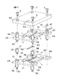
各セルユニット同士はロッド3A,3B,3Cによって一体化されており、上下端部分のロッド3A,3B,3Cは絶縁性のパネル4A,4Bにそれぞれ固定されている。図4は、セルユニットU6,U5の部分の分解斜視図である。ロッド3Aは銅等の電導性材料により形成され、ロッド3B,3Cは樹脂等の電気絶縁性の材料により形成されている。ロッド3A〜3C同士の接続はネジ締結により行われる。すなわち、ロッド3Aの下端側に形成された雄ねじ部30とロッド3Bの上端側に形成された雌ねじ部31をネジ締結することにより、ロッド3Aの下部にロッド3Bを接続する。さらに、ロッド3Bの下端側に形成された雄ねじ部30とロッド3Aの上端側に形成された雌ねじ部31をネジ締結することにより、ロッド3Bの下部にロッド3Aを接続する。ロッド3Cとロッド3Aとの接続も同様である。
【0014】
図4のロッド3Aとその下側のロッド3Bとの間には、セル電圧検出線6gが挟み込まれるように取り付けられる。ロッド3Bとその下側のロッド3Aとの間には、セル電圧検出線6eが挟み込まれるように取り付けられる。また、ロッド3Cとロッド3Aとの間には、セル電圧検出線6fが挟み込まれるように取り付けられる。各ロッド3Aはバスバー2A,2Bに形成された貫通孔20に貫挿される。これによって、各バスバー2A,2Bの、すなわち各セルユニットU1〜U6の横ズレが防止される。
【0015】
図1に示すように、最下端部のロッド3A,3Cは、雄ねじ30を用いてパネル4Bに固定される。一方、パネル4Aはボルト5により最上端部のロッド3A,3Cに固定される。各ロッド3A〜3Cがそれぞれ接続されたならば、各セルユニットU1〜U6のバスバー2A,2Bを図1に示すようにロッド3Aに溶接等により固定する。これにより、バスバー2Aとバスバー2Bとがロッド3Aを介して電気的に接続され、バスバー2A,2Bおよびロッド3Aは同電位に設定される。
【0016】
その結果、セルユニットU1の負極側バスバー2Bは上側に配設されたセルユニットU2の正極側バスバー2Aに接続され、セルユニットU2の負極側バスバー2Bはその上側に配設されたセルユニッU3の正極側バスバー2Aに接続される。すなわち、セルユニットU1〜U3は直列接続される。セルユニットU4〜U5に関しても同様に直列接続される。また、セルユニットU1のバスバー2AとセルユニットU2のバスバー2Bとは、ロッド3Bによって電気的に絶縁されている。
【0017】
上述したように、本実施の形態では、バスバー2A,2Bはセル1のタブ1b,1cの伸延方向に設けられ、タブ1b,1cは曲げられること無くバスバー2A,2Bに接続される。そして、直列接続の際に同電位に設定されるバスバー2A,2B同士を、導電性のロッド3Aで接続するようにしている。例えば、図5のように共通のバスバー200を用いてタブ1b,1cを接続する一般的な接続方法の場合には、タブ1b、1cが折り曲がるのを避けることができなかったが、本実施の形態では、このようなタブ1b,1cの屈曲を防止することができる。その結果、タブ1b,1cの強度確保や耐久性・信頼性の向上を図ることができる。さらに、セルユニットU1〜U6の位置ズレを防止するために設けられたロッド3A〜3Cの一部(ロッド3A)を、バスバー間の電気的接続に兼用して用いているので、部品点数およびコストの増加を抑えることが可能である。更に、ロッド接続時にロッド3A、3B間にセル電圧検出線6a〜6gを挟み込むことにより、検出線6a〜6gのバスバー2A、2Bへの接続が簡単にできるとともに、確実な接続を行うことができる。
【0018】
[変形例]
図7は、バスバー2A,2Bとロッド3A,3Bと接続構造の変形例を示す図である。ロッド3Aとロッド3Bとの接続構造は上述したものと同様である。バスバー3Aおよびセル電圧検出線6aの取付部分はロッド3Bの雄ねじ部30のみが貫通し、このネジ接続部にバスバー3Aおよびセル電圧検出線6a(例えば、セル電圧検出線6aの取り付けられた圧着端子)を挟持するようにロッド3Aとロッド3Bとを接続する。この場合、バスバー2A,2Bのロッド3Aへの溶接を必要とせず、組立が容易となる。
【0019】
上述した実施の形態では、2個並列接続したものを6段直列接続したが、並列接続数や直列接続数は実施の形態に限定されない。また、複数個のセルを上下に並列接続する場合にも、本発明を適用することができる。なお、上述した特徴的な機能作用効果が得られるものであるならば、本発明は上述した実施の形態に限定されない。
【0020】
以上説明した実施の形態と特許請求の範囲の要素との対応において、正極タブ1bは正極端子を、負極タブ1cは負極端子を、ロッド3Aは導電性柱状部材を、ロッド3B,3Cは電気的絶縁性柱状部材をそれぞれ構成する。
【図面の簡単な説明】
【図1】セルモジュ−ルMの正面図である。
【図2】図1のA−A断面図である。
【図3】図1のB矢視図である。
【図4】セルユニットU6,U5の部分の分解斜視図である。
【図5】共通のバスバー200を用いてタブ1b,1cを接続する一般的な接続方法を示す図である。
【図6】セル1の内部構造を説明する断面図である。
【図7】変形例を示す図である。
【符号の説明】
1 セル
1a セル本体
1b 正極タブ
1c 負極タブ
2A,2B バスバー
3A,3B,3C ロッド
4A,4B パネル
5 ボルト
6a〜6f セル電圧検出線
M セルモジュール
U1〜U6 セルユニット[0001]
BACKGROUND OF THE INVENTION
The present invention relates to a cell module in which a plurality of tab-type cells such as a sheet-like thin battery are stacked and arranged.
[0002]
[Problems to be solved by the invention]
A thin battery as disclosed in Japanese Patent Application Laid-Open No. 9-259859 is known as a tab-type cell in which a sheet-like positive electrode terminal and a negative electrode terminal are drawn from both ends of a cell body. In order to obtain a high-voltage, high-capacity battery using these cells, it is necessary to form a battery pack by connecting a plurality of cells in series or in parallel. When connecting the tab terminals of the cells that are vertically stacked, it is necessary to connect the tab terminals by bending them. For this reason, stress is generated in the tab terminal portion, and the durability and reliability of the tab terminal may be reduced.
[0003]
An object of the present invention is to provide a cell module that is excellent in durability and reliability without causing unnecessary stress in a tab in a cell module in which a plurality of tab-type cells are stacked and arranged. .
[0004]
[Means for Solving the Problems]
In the cell module according to the present invention, both tab-type cells having a sheet-like positive electrode terminal and a negative electrode terminal are arranged in parallel, and each terminal on the same electrode side is connected to a bus bar arranged in the terminal extending direction. One cell unit is configured. A plurality of cell units are stacked and disposed so that bus bars having different polarities face each other, thereby forming a cell module. The cell module passes through a through-hole formed in the bus bar of each cell unit and penetrating in the stacking direction of the cell unit and through holes of a plurality of bus bars arranged in the stacking direction, and the bus bar is orthogonal to the stacking direction. A positioning member that positions at a predetermined position with respect to the direction, and the positioning member is different from the conductive columnar member that electrically connects bus bars set at the same potential adjacent in the stacking direction and adjacent in the stacking direction. Insulating columnar members that electrically insulate bus bars set to potentials are alternately connected in the stacking direction, and a plurality of cell units are connected in series by conductive columnar members. And
[0005]
【The invention's effect】
According to the present invention, a pair of substantially plate-shaped bus bars is provided for each cell unit composed of a plurality of tab-type cells arranged in parallel, the positive terminals of each cell are on one bus bar, and the negative terminals are Each is connected to the other bus bar. And the bus bars set to the same potential of the adjacent cell units are electrically connected by the positioning member. Therefore, the bus bar can be arranged in the extending direction of each terminal, and can be connected to the bus bar without bending the sheet-like terminal. As a result, it is possible to prevent the terminal from being stressed and to improve the durability and reliability of the terminal portion.
[0006]
DETAILED DESCRIPTION OF THE INVENTION
Embodiments of the present invention will be described below with reference to the drawings. 1 to 3 are views showing an embodiment of a cell module according to the present invention. 1 is a front view of the cell module M, FIG. 2 is a cross-sectional view taken along the line AA in FIG. 1, and FIG. 3 is a view taken in the direction of arrow B in FIG. The cell module M shown in FIGS. 1 to 3 is composed of 12
[0007]
FIG. 6 is a view for explaining the internal structure of the
[0008]
The
[0009]
Each of the
[0010]
The bag-like
[0011]
The cell module M of the present embodiment includes twelve
[0012]
As shown in FIG. 2, in the two
[0013]
The cell units are integrated by
[0014]
A cell
[0015]
As shown in FIG. 1, the
[0016]
As a result, the negative electrode
[0017]
As described above, in this embodiment, the bus bars 2A and 2B are provided in the extending direction of the
[0018]
[Modification]
FIG. 7 is a view showing a modified example of the connection structure between the bus bars 2A and 2B and the
[0019]
In the embodiment described above, two parallel-connected ones are connected in series in six stages, but the number of parallel connections and the number of series connections are not limited to the embodiment. The present invention can also be applied to a case where a plurality of cells are connected in parallel vertically. Note that the present invention is not limited to the above-described embodiment as long as the above-described characteristic functions and effects can be obtained.
[0020]
In the correspondence between the embodiment described above and the elements of the claims, the
[Brief description of the drawings]
FIG. 1 is a front view of a cell module M. FIG.
FIG. 2 is a cross-sectional view taken along the line AA of FIG.
FIG. 3 is a view taken in the direction of arrow B in FIG. 1;
FIG. 4 is an exploded perspective view of a portion of cell units U6 and U5.
FIG. 5 is a diagram showing a general connection method for connecting
6 is a cross-sectional view illustrating the internal structure of
FIG. 7 is a diagram showing a modified example.
[Explanation of symbols]
1
Claims (5)
各セルユニットのバスバーに形成された、前記セルユニットの積層方向に貫通する貫通孔と、
積層方向に並んだ前記複数のバスバーの前記貫通孔を貫通して、前記バスバーを前記積層方向に直交する方向に対して所定位置に位置決めする位置決め部材とを備え、
前記位置決め部材は、積層方向に隣接した同電位に設定されるバスバー同士を電気的に接続する導電性柱状部材と、積層方向に隣接した異なる電位に設定されるバスバー同士を電気的に絶縁する絶縁性柱状部材とを前記積層方向に交互に接続して形成され、
前記複数のセルユニットは、前記導電性柱状部材によって直列に接続されていることを特徴とするセルモジュール。A plurality of tab-type cells each having a sheet-like positive electrode terminal and a negative electrode terminal extending in opposite directions from the outer peripheral edge of the cell body are arranged in parallel, and are arranged in the terminal extension direction, and are identical among the terminals. A cell module in which a plurality of cell units in which pole terminals are connected by a pair of substantially plate-like bus bars are arranged so that bus bars having different polarities face each other,
A through-hole formed in the bus bar of each cell unit and penetrating in the stacking direction of the cell units;
A positioning member that passes through the through holes of the plurality of bus bars arranged in the stacking direction and positions the bus bar at a predetermined position with respect to a direction orthogonal to the stacking direction ;
The positioning member electrically insulates electrically conductive columnar members that electrically connect bus bars set at the same potential adjacent in the stacking direction and bus bars set at different potentials adjacent in the stacking direction. Formed by alternately connecting the columnar members in the stacking direction,
The cell module, wherein the plurality of cell units are connected in series by the conductive columnar member .
前記位置決め部材は、前記導電性柱状部材と前記絶縁性柱状部材とを前記積層方向に交互に接続したロッドであることを特徴とするセルモジュール。The cell module according to claim 1,
The cell module, wherein the positioning member is a rod in which the conductive columnar member and the insulating columnar member are alternately connected in the stacking direction .
前記両タブ型セルの電圧検出線を挟持するように前記導電性柱状部材と前記電気的絶縁性柱状部材とを接続したことを特徴とするセルモジュール。The cell module according to claim 2, wherein
Cell module, characterized by that connecting the electrically insulative columnar member and the conductive columnar member so as to hold a voltage detection line of the two tabs type cell.
前記導電性柱状部材と前記絶縁性柱状部材とで前記バスバーを挟持することを特徴とするセルモジュール。A cell module, wherein the bus bar is sandwiched between the conductive columnar member and the insulating columnar member.
前記導電性柱状部材と前記絶縁性柱状部材とは互いにネジ締結されていることを特徴とするセルモジュール。The cell module, wherein the conductive columnar member and the insulating columnar member are screwed to each other.
Priority Applications (1)
| Application Number | Priority Date | Filing Date | Title |
|---|---|---|---|
| JP2002185809A JP3912201B2 (en) | 2002-06-26 | 2002-06-26 | Cell module |
Applications Claiming Priority (1)
| Application Number | Priority Date | Filing Date | Title |
|---|---|---|---|
| JP2002185809A JP3912201B2 (en) | 2002-06-26 | 2002-06-26 | Cell module |
Publications (2)
| Publication Number | Publication Date |
|---|---|
| JP2004031122A JP2004031122A (en) | 2004-01-29 |
| JP3912201B2 true JP3912201B2 (en) | 2007-05-09 |
Family
ID=31181331
Family Applications (1)
| Application Number | Title | Priority Date | Filing Date |
|---|---|---|---|
| JP2002185809A Expired - Fee Related JP3912201B2 (en) | 2002-06-26 | 2002-06-26 | Cell module |
Country Status (1)
| Country | Link |
|---|---|
| JP (1) | JP3912201B2 (en) |
Families Citing this family (22)
| Publication number | Priority date | Publication date | Assignee | Title |
|---|---|---|---|---|
| JP3731595B2 (en) * | 2003-10-10 | 2006-01-05 | 日産自動車株式会社 | Assembled battery |
| EP1530247A3 (en) * | 2003-10-10 | 2005-05-18 | Nissan Motor Co., Ltd. | Battery comprising a stack of unit cells and method of making the same |
| JP4461940B2 (en) * | 2004-07-20 | 2010-05-12 | 日産自動車株式会社 | Assembled battery |
| JP4961695B2 (en) * | 2004-10-22 | 2012-06-27 | 日産自動車株式会社 | Assembled battery and assembled battery assembly method |
| JP4848733B2 (en) * | 2004-10-22 | 2011-12-28 | 日産自動車株式会社 | Battery module and battery pack |
| US7659029B2 (en) | 2004-10-26 | 2010-02-09 | Nissan Motor Co., Ltd. | Battery module with insulating plates nipping electrode tabs |
| JP4992244B2 (en) * | 2005-04-07 | 2012-08-08 | 日産自動車株式会社 | Battery module and battery pack |
| WO2007006169A1 (en) * | 2005-05-31 | 2007-01-18 | Hingka Chung | A plug-connect conduction type large capacity lithium-ion battery |
| JP5046956B2 (en) * | 2005-12-01 | 2012-10-10 | 日本電気株式会社 | Method for manufacturing electrical device assembly |
| JP4904863B2 (en) * | 2006-03-15 | 2012-03-28 | 日産自動車株式会社 | Battery module and manufacturing method thereof |
| KR100895203B1 (en) * | 2006-05-15 | 2009-05-06 | 주식회사 엘지화학 | Middle or Large-sized Battery Module |
| JP5217323B2 (en) * | 2007-09-14 | 2013-06-19 | 株式会社明電舎 | Bipolar multilayer electric double layer capacitor |
| JP5505962B2 (en) * | 2009-11-13 | 2014-05-28 | Necエナジーデバイス株式会社 | Battery pack and battery pack connection method |
| KR101038680B1 (en) * | 2010-03-12 | 2011-06-02 | 아이피지 포토닉스 코리아(주) | Secondary battery and module using the same |
| KR101271567B1 (en) * | 2010-08-16 | 2013-06-11 | 주식회사 엘지화학 | Battery Module of Structure Having Fixing Member Inserted into Through-Hole of Plates and Battery Pack Employed with the Same |
| JP5601253B2 (en) * | 2011-03-15 | 2014-10-08 | 株式会社デンソー | Battery internal pressure state detection device |
| KR101201066B1 (en) | 2011-06-14 | 2012-11-14 | 삼성에스디아이 주식회사 | Battery pack |
| JP2015125878A (en) * | 2013-12-26 | 2015-07-06 | 株式会社デンソー | Battery cell and battery pack |
| JP6369059B2 (en) * | 2014-03-12 | 2018-08-08 | 株式会社豊田自動織機 | Fastening member |
| JP2015230892A (en) | 2014-06-09 | 2015-12-21 | ソニー株式会社 | Battery module, power storage device, power storage system, electronic apparatus, electric vehicle and power system |
| JP6250885B2 (en) * | 2014-07-08 | 2017-12-20 | 株式会社キャプテックス | Battery pack |
| JP6596866B2 (en) * | 2015-03-24 | 2019-10-30 | 三菱自動車工業株式会社 | Battery case |
-
2002
- 2002-06-26 JP JP2002185809A patent/JP3912201B2/en not_active Expired - Fee Related
Also Published As
| Publication number | Publication date |
|---|---|
| JP2004031122A (en) | 2004-01-29 |
Similar Documents
| Publication | Publication Date | Title |
|---|---|---|
| JP3912201B2 (en) | Cell module | |
| JP3596537B2 (en) | Connection structure of thin battery and assembled battery | |
| US8420249B2 (en) | Battery module and battery pack | |
| US7666542B2 (en) | Flat battery and battery pack | |
| US10903462B2 (en) | Electric storage device | |
| CN106605317B (en) | Assembled battery | |
| EP2197065B1 (en) | Terminal connection apparatus for battery cells having foil terminals | |
| CN108140771B (en) | Terminal arrangement for an energy storage device | |
| WO2014142148A1 (en) | Power source | |
| EP3840085A1 (en) | Battery module | |
| CN109390520B (en) | Electricity storage device | |
| JP2013187046A (en) | Battery pack | |
| EP2874204B1 (en) | Battery assembly | |
| JP3606278B2 (en) | Battery terminal connection structure | |
| JP5505962B2 (en) | Battery pack and battery pack connection method | |
| CN110299500B (en) | Battery structure | |
| JP5481970B2 (en) | Battery module and manufacturing method thereof | |
| JP4977356B2 (en) | Electrical device assembly | |
| JP2013187104A (en) | Battery module, and flat battery cell | |
| JP4593056B2 (en) | Plate battery connection structure | |
| JP2015005488A (en) | Planar battery pack and planar battery pack group constituted by combining a plurality of them | |
| JP7087959B2 (en) | Batteries assembled | |
| JP3775356B2 (en) | Laminated and assembled batteries | |
| JP2003346780A (en) | Insulating structure of electrode for battery pack and insulating body | |
| JP3900024B2 (en) | A cell unit composed of multiple tab-type cells |
Legal Events
| Date | Code | Title | Description |
|---|---|---|---|
| A977 | Report on retrieval |
Free format text: JAPANESE INTERMEDIATE CODE: A971007 Effective date: 20060320 |
|
| A131 | Notification of reasons for refusal |
Free format text: JAPANESE INTERMEDIATE CODE: A131 Effective date: 20060808 |
|
| A521 | Written amendment |
Free format text: JAPANESE INTERMEDIATE CODE: A523 Effective date: 20060929 |
|
| TRDD | Decision of grant or rejection written | ||
| A01 | Written decision to grant a patent or to grant a registration (utility model) |
Free format text: JAPANESE INTERMEDIATE CODE: A01 Effective date: 20070109 |
|
| A61 | First payment of annual fees (during grant procedure) |
Free format text: JAPANESE INTERMEDIATE CODE: A61 Effective date: 20070122 |
|
| R150 | Certificate of patent or registration of utility model |
Free format text: JAPANESE INTERMEDIATE CODE: R150 |
|
| FPAY | Renewal fee payment (event date is renewal date of database) |
Free format text: PAYMENT UNTIL: 20110209 Year of fee payment: 4 |
|
| FPAY | Renewal fee payment (event date is renewal date of database) |
Free format text: PAYMENT UNTIL: 20120209 Year of fee payment: 5 |
|
| FPAY | Renewal fee payment (event date is renewal date of database) |
Free format text: PAYMENT UNTIL: 20120209 Year of fee payment: 5 |
|
| FPAY | Renewal fee payment (event date is renewal date of database) |
Free format text: PAYMENT UNTIL: 20130209 Year of fee payment: 6 |
|
| FPAY | Renewal fee payment (event date is renewal date of database) |
Free format text: PAYMENT UNTIL: 20130209 Year of fee payment: 6 |
|
| FPAY | Renewal fee payment (event date is renewal date of database) |
Free format text: PAYMENT UNTIL: 20140209 Year of fee payment: 7 |
|
| LAPS | Cancellation because of no payment of annual fees |