EP1710602B1 - Système de mesure pour la détermination de six degrés de liberté d'un objet - Google Patents
Système de mesure pour la détermination de six degrés de liberté d'un objet Download PDFInfo
- Publication number
- EP1710602B1 EP1710602B1 EP06405125A EP06405125A EP1710602B1 EP 1710602 B1 EP1710602 B1 EP 1710602B1 EP 06405125 A EP06405125 A EP 06405125A EP 06405125 A EP06405125 A EP 06405125A EP 1710602 B1 EP1710602 B1 EP 1710602B1
- Authority
- EP
- European Patent Office
- Prior art keywords
- reflector
- angle
- measurement
- light source
- light
- Prior art date
- Legal status (The legal status is an assumption and is not a legal conclusion. Google has not performed a legal analysis and makes no representation as to the accuracy of the status listed.)
- Active
Links
Images


Classifications
-
- G—PHYSICS
- G01—MEASURING; TESTING
- G01S—RADIO DIRECTION-FINDING; RADIO NAVIGATION; DETERMINING DISTANCE OR VELOCITY BY USE OF RADIO WAVES; LOCATING OR PRESENCE-DETECTING BY USE OF THE REFLECTION OR RERADIATION OF RADIO WAVES; ANALOGOUS ARRANGEMENTS USING OTHER WAVES
- G01S17/00—Systems using the reflection or reradiation of electromagnetic waves other than radio waves, e.g. lidar systems
- G01S17/66—Tracking systems using electromagnetic waves other than radio waves
-
- G—PHYSICS
- G01—MEASURING; TESTING
- G01S—RADIO DIRECTION-FINDING; RADIO NAVIGATION; DETERMINING DISTANCE OR VELOCITY BY USE OF RADIO WAVES; LOCATING OR PRESENCE-DETECTING BY USE OF THE REFLECTION OR RERADIATION OF RADIO WAVES; ANALOGOUS ARRANGEMENTS USING OTHER WAVES
- G01S17/00—Systems using the reflection or reradiation of electromagnetic waves other than radio waves, e.g. lidar systems
- G01S17/02—Systems using the reflection of electromagnetic waves other than radio waves
- G01S17/06—Systems determining position data of a target
- G01S17/42—Simultaneous measurement of distance and other co-ordinates
-
- G—PHYSICS
- G01—MEASURING; TESTING
- G01S—RADIO DIRECTION-FINDING; RADIO NAVIGATION; DETERMINING DISTANCE OR VELOCITY BY USE OF RADIO WAVES; LOCATING OR PRESENCE-DETECTING BY USE OF THE REFLECTION OR RERADIATION OF RADIO WAVES; ANALOGOUS ARRANGEMENTS USING OTHER WAVES
- G01S5/00—Position-fixing by co-ordinating two or more direction or position line determinations; Position-fixing by co-ordinating two or more distance determinations
- G01S5/16—Position-fixing by co-ordinating two or more direction or position line determinations; Position-fixing by co-ordinating two or more distance determinations using electromagnetic waves other than radio waves
- G01S5/163—Determination of attitude
Definitions
- the invention is in the field of metrology and relates to a measuring system according to the preamble of the first independent claim.
- the measuring system is used to determine six degrees of freedom of an object, in particular a moving object, namely three position coordinates of a reference point on the object and three rotation angles (tilt, yaw and roll angle) about three orthogonal axes that run through the object and, for example, in Cross reference point.
- Methods for determining the six degrees of freedom of an object are known, for example, in which laser trackers equipped with distance meters, theodolites or theodolite-like measuring devices are used. With these, direction and distance (polar coordinates) are measured to a plurality of reflector-marked points in known positions on the object. From the measured coordinates of the points is then closed on the six degrees of freedom of the object relative to a predetermined coordinate system, for example relative to a meter-own coordinate system. Since the marked points are targeted and measured one after the other, the method is particularly suitable for stationary or slowly moving objects.
- Photogrammetric methods are also known in which a plurality of cameras from different positions image an array of light spots (e.g., white or reflective marks, spots illuminated by light rays or reflectors or active light sources) placed on the article in known positions. From the positions of the light spots on the different camera images, the directions to the light spots relative to the optical axis of the respective camera and from the total amount of data become the position and orientation of the light spot array and possibly also the position and orientation of the camera (s) in a given coordinate system certainly. Since such photogrammetric determinations of the six degrees of freedom are only suitable for moving objects, if a plurality of simultaneously operating, advantageously stationary and calibrated cameras are provided, the method is relatively complex, also with regard to data volumes to be managed.
- light spots e.g., white or reflective marks, spots illuminated by light rays or reflectors or active light sources
- the patent EP-0607303 (metronor ) proposed to use only one camera.
- the data obtained from a single camera image is sufficient to determine the six degrees of freedom of the light dot array relative to the camera, albeit with respect to depth, that is, the distance between the camera and the light dot array no high accuracy can be achieved.
- the object on which the light spots are arranged is, for example, a stylus, wherein the position and orientation of the stylus on the position and orientation of a point to be measured, which is palpated with the stylus is closed.
- EP-0880674 proposed to combine the only camera with a distance measuring device, wherein as a distance measuring device, a so-called laser range finder is called, thus working with a laser beam as a measuring beam device, and wherein on the object in addition to the camera to be detected with the light points a reflector for reflection of the measuring beam is provided back into the distance measuring device.
- the reflector which can also be one of the light points to be detected by the camera, also has a known position in the light point arrangement.
- the measuring system has a laser tracker which is equipped with a distance measuring device.
- the laser tracker directs a laser beam (measuring beam) onto the reflector and tracks it as it moves, whereby the direction of the measuring beam is detected relative to the tracker.
- the reflector is a retroreflector (cube-corner reflector or cube-corner prism) whose apical tip is replaced by an apical (cube-corner reflector) or apical (cube-corner prism) face parallel to the entrance face, the apical opening or face being smaller is the cross section of the measuring beam.
- a CCD charge coupled device, as in a digital camera usual
- PSD position sensitive device
- the image coordinates (x, y) of the location at which the measurement beam part impinges on this surface are a direct measure of the angle of incidence of the measurement beam into the reflector (spatial angle between measurement beam and reflector axis) or for rotation angle of the reflector axis about two perpendicular to the measuring beam aligned axes (tilt and yaw or two degrees of freedom of orientation of the reflector or object).
- the measuring system should not be inferior in terms of accuracy to the measuring systems briefly described above and should be feasible with known measuring devices.
- the inventive measuring system is based on the measuring system described above, with the five degrees of freedom (three position coordinates, and tilt and yaw) of a reflector or an object on which the reflector is arranged, can be determined.
- the inventive measuring system is compared to the known system expanded by an optically detectable additional element, by the optical detection of a rotation of the reflector or the object about the reflector axis or to the measuring beam (roll angle) can be determined.
- the measuring system has an angle and distance measuring device based on a laser beam (measuring beam) and a reflector, the reflector being the object whose six degrees of freedom are to be determined, or is arranged on this object.
- the reflector has the apical opening or surface described above and the photosensitive surface arranged behind the reflector apex.
- the measuring system also has a computer which is equipped to calculate the six degrees of freedom of the reflector or object from the measured data.
- the optically detectable additional element is stationary at least during the measurement relative to the reflector and is detected by the angle and distance measuring device or it is stationary relative to the angle and distance measuring device and is detected by the object.
- the optically detectable additional element is designed and arranged such that it defines a direction or a straight line in a plane which is not aligned parallel to the reflector axis or to the measuring beam, which can be determined from measurement data obtained by the optical detection of the additional element.
- An angle between the said direction or straight line and a corresponding predetermined reference direction or straight represents a measure for an absolute roll angle (sixth degree of freedom), an angle between two successively detected such directions or straight lines a measure for a roll angle change.
- the optically detectable additional element is not rotationally symmetric with respect to axes of rotation which contain as many possible measuring beam directions as possible or has a rotational symmetry with a symmetry angle of 180 °, ie the direction or straight line defined by the additional element is not parallel to such axes of rotation and its An image detected in an image plane coincides with a rotation through 360 ° or optionally through 180 °.
- the object whose six degrees of freedom are determined according to the invention is the reflector itself or an object on which the reflector at least during the measurement is stationary.
- the object is, for example, a hand-held stylus or a movable, for example, also hand-guided scanner (eg laser scanner), which is closed on the determined in the manner mentioned above six degrees of freedom of the stylus on the position of a touch point or scan point.
- the object may also be an object to be controlled on a given path, such as a robotic arm or a vehicle, for which control the six degrees of freedom determined are compared to corresponding setpoints and drives corresponding to the deviations are activated.
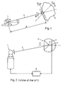
- FIG. 1 shows the six degrees of freedom to be determined in the measuring system according to the invention. Shown are very schematically the angle and distance measuring device 1, the reflector 2, which is arranged on an object 3, and directed by the angle and distance measuring device 1 on the reflector 2 measuring beam 4.
- the angle and distance measuring device 1 measures relative to a through the device defined coordinate system (not shown), the polar coordinates of the reflector ⁇ , ⁇ and d.
- the non-illustrated photosensitive surface behind the reflector apex measures the tilt angle ⁇ and the yaw angle ⁇ of the reflector relative to the measurement beam.
- the sixth degree of freedom is the roll angle ⁇ relative to the reflector axis or to the measuring beam 4. All specific degrees of freedom can be converted into further coordinate systems with known algorithms if the position and orientation of the angle and distance measuring device 1 own coordinate system in the further coordinate system known or determinable.
- FIG. 2 shows the measuring system according to the invention underlying, known measuring system for determining the five degrees of freedom ⁇ , ⁇ , d, ⁇ and ⁇ of the reflector 2 or an object on which the reflector is arranged.
- This measuring system includes the angle and distance measuring device 1 operating with a laser beam (measuring beam 4), which is for example a laser tracker or theodolite equipped with a distance meter, and the reflector 2, which is equipped to reflect the incident measuring beam 4, in such a way that incident and reflected beam are parallel to each other, regardless of the direction in which the measuring beam 4 falls on the reflector 2.
- a laser beam measuring beam 4
- the reflector 2 which is equipped to reflect the incident measuring beam 4
- the angle and distance measuring device 1 is equipped to determine the spatial direction of the measuring beam and to analyze the reflected measuring beam and to deduce a path length of the measuring beam or a path length change (absolute or relative distance measurement).
- the reflector 2 is a triple mirror or a cube-corner prism, wherein the apex of the reflector is not pointed, but has an opening (triple mirror) or parallel to the entrance surface aligned exit surface 6 (cube corner prism), wherein opening or surface 6 is smaller than the cross section of the measuring beam 4.
- photosensitive surface 7 which is for example a CCD or PSD. This surface 7 generates a measurement signal which corresponds to the position P (two image coordinates) of the incident measuring beam part and represents a direct measure of the tilt and yaw angle of the reflector axis A relative to the measuring beam 4.
- the reflector axis A is perpendicular to the photosensitive surface 7 aligned and pierces them in their center.
- the reflector axis A represents the z-axis of the object's own coordinate system and the optical center of the reflector 2 the coordinate origin.
- FIG. 3 shows an exemplary embodiment of the inventive measuring system in which the optically detectable additional element 10 is arranged on the object 3 and is detected by an additional detection means 11 on the angle and distance measuring device 1.
- the additional element 10 consists for example of two light points 12 and 13.
- the additional detection means 11 is equipped to image the additional element 10 in an image plane. It is, for example, a camera 15 with a CCD, which is at least stationary during the measurement relative to the measuring beam.
- the two points of light 12 and 13 are passive marks, reflectors, active light sources or points generated by light rays directed against the object. They are advantageously arranged in a plane which extends approximately transversely to the reflector axis, which advantageously makes a connection between the two light points approximately centrally.
- a connecting line that can be determined from such images has a unique direction 21.
- An angle 22 between the directed connecting line 21 and a corresponding, also directed reference line 21 ' is a measure of the roll angle of the reflector 2 or article 3, said angle 22 from a camera-own coordinate system in the coordinate system of the angle and distance measuring device or in Another, predetermined coordinate system is to be transformed if the camera axis is not aligned with the measuring beam 4.
- a direction can be detected from the images 20 of the additional element 10 created by the camera 15 (light points distinguishable from one another)
- a single angle 22 results. If only one straight line can be determined from the image (light points can not be distinguished from one another), two angles 22 result differ by a reflector rotation of 180 °. In the latter case, however, an unambiguous determination of the roll angle may be possible if a restriction of the measuring range precludes one of the resulting angles or if in a relative measurement one of the resulting angles is not realistic.
- the reflector 2 can also function as one of the light spots 12 or 13 if the camera 15 is aligned coaxially with the measuring beam 4 or if the reflector 2 is illuminated by the camera 15, for example by a flash light (not shown).
- FIGS. 4 and 5 show two exemplary such additional elements 10th
- FIG. 4 shows an additional element 10 in the form of a flat arrow from the image of a direction 22 is eruierbar.
- FIG. 5 shows an additional element 10, which consists of a triangle and a cross, with one corner of the triangle is aligned with a cross leg and this directionally distinguished. The triangular corners are marked, for example, by active points of light, the cross legs are painted or glued on the object.
- the cross legs are designed, for example, as black double lines on a white background. This has the advantage that from a short distance the space between the black lines and from a greater distance the black double line as a whole for the determination of the direction 21 from the picture of the additional element can be analyzed. Thus, even with a detection by a zoom-less camera 15 at very different distances between the camera 15 and additional element 10, an equivalent accuracy can be achieved.
- FIG. 6 shows a further exemplary embodiment of the measuring system according to the invention, which in turn has an angle and distance measuring device 1 and a reflector 2 arranged on an object 3 with a light-sensitive surface 7 arranged behind the reflector apex.
- the additional element 10 in this embodiment is a light source 30, which is arranged on the angle and distance measuring device 1 and which is detectable by the photosensitive surface 7 as a light spot. Light from the light source 30 must therefore strike the photosensitive surface 7 at least during the measurement through the apex opening or surface of the reflector and be detectable there as a pixel without disturbing the detection of the measuring beam 4.
- the light source 30 may be rotatably mounted stationary on the angle and distance measuring device or advantageously with the measuring beam about the vertical axis of the measuring device and emit diffused light in approximately the direction of the reflector, as shown in the FIG. 6 is indicated.
- the light source 30 may also be accurate based on the measurement data provided by the angle and distance meter be the reflector aligned laser.
- a laser is also conceivable which emits a laser beam lying in the same vertical plane with the measuring beam, this laser beam being widened in this plane by corresponding optics (eg cylindrical lens) or the laser or a light guide end guiding the laser beam scanning in this plane performs.
- a sensor is also provided, which detects the laser beam reflected by the reflector of the light source 30, wherein the sensor signal synchronized to synchronize the detection by the photosensitive surface 7 with the impact of the laser beam on this.
- the photosensitive surface 7 not only the measuring beam 4 but also a light beam emanating from the light source 30 are detected on the photosensitive surface 7, the light points on the surface 7 either being distinguishable from one another (different intensities or wavelengths) or detected in succession.
- the photosensitive surface must be equipped accordingly, for example as a CCD, and a PSD can also be used for a successive detection.
- FIGS. 7 and 8 show two examples of images of the measuring beam 4 and the light source 30 on the photosensitive surface 7, as well as the direction 21 and the angle 22 to be determined therefrom. Furthermore, a circle 31 is shown, on which the pixel representing the light source 30 moves at a varying roll angle.
- FIG. 7 represents a case in which the measuring beam 4 is perpendicular to the reflector 2 and the corresponding pixel lies in the center of the photosensitive surface 7,
- FIG. 8 a case in which the measuring beam 4 obliquely hits the reflector and the corresponding pixel is eccentrically on the photosensitive surface 7, wherein from this eccentricity two degrees of freedom and from the direction 21 from one pixel to another of the third degree of freedom of the reflector orientation can be calculated.
- FIGS. 9 and 10 show a further exemplary embodiment of the inventive measuring system in which the optically detectable additional element 10 is disposed on the angle and distance measuring device 1 and for its detection on the object 3, an additional detection means 11 is provided.
- the additional element 10 is in turn a light source 30 which is arranged on the angle and distance measuring device 1 and emits the light in the vertical plane of the measuring beam 4.
- the light source 30 is, for example, a laser and an optical element which spreads the laser beam in said plane (For example, cylindrical lens) or it is a laser that emits a laser beam in the said plane performing a scanning movement.
- the additional detection means 11 is a ring sensor 40 arranged, for example, concentric with the reflector and arranged in the FIG. 10 is shown as a front view. This ring sensor 40 has an annular array of photosensitive elements 41, these elements 41 being arranged in the row such that the substantially vertical light line 42 thrown from the light source 30 onto the sensor strikes and detects one or two photosensitive elements becomes.
- the annular row of photosensitive elements 41 of the ring sensor 40 according to FIG. 10 has photosensitive elements 41 opposite gaps 43, so that the light line 42, which is thrown from the light source 30 to the ring sensor, only one element 41 is detected. From this detection is not a direction, but a straight eruierbar.
- For detection of one direction use is made of a continuous ring of photosensitive elements 41 as a sensor, which detects the light line 42 at two locations, and the light source 30 is to be equipped for a scanning light beam movement. From the temporal succession of the two detections can then be closed to one direction.
Claims (5)
- Système de mesure destiné à déterminer trois coordonnées de position (α, β, d) et les angles d'inclinaison, de lacet et de roulis (ϕ, χ, ψ) d'un réflecteur (2) ou d'un objet (3) sur lequel le réflecteur (2) est disposé,
le système de mesure présentant un appareil (1) de mesure d'angle et de distance qui travaille avec un faisceau laser comme faisceau de mesure (4), le réflecteur (2) et un calculateur (8),
le réflecteur (2) étant équipé pour réfléchir parallèlement le faisceau de mesure (4) et présentant à une ouverture ou surface apicale (6) telles qu'une partie du faisceau de mesure (4) dirigé sur le réflecteur (2) aboutisse à travers l'ouverture ou surface apicale (6) sur une surface photosensible (7) disposée en arrière du sommet du réflecteur, le calculateur (8) étant équipé pour calculer à partir des données de mesure fournies par l'appareil (1) de mesure d'angle et de distance et par la surface photosensible (7) les trois coordonnées de position (α, β, d) ainsi que l'angle d'inclinaison et l'angle de lacet (ϕ, χ) du réflecteur (2) ou de l'objet (3),
caractérisé en ce que
le système de mesure présente une autre source de lumière (30) disposée sur l'appareil (1) de mesure d'angle et de distance et dont la lumière peut être détectée par la surface photosensible (7), la lumière de l'autre source de lumière (30) étant incidente' sur la surface photosensible (7) à travers l'ouverture ou surface apicale (6) du réflecteur (2) au moins pendant la mesure ou pouvant être détectée par un détecteur annulaire (40) disposé autour du réflecteur, une ligne lumineuse (42) étant projetée sur l'objet par l'autre source de lumière (30) et pouvant être détectée par une rangée annulaire d'éléments photosensibles (41) du détecteur annulaire (40),
en ce que l'autre source de lumière (30) définit une direction (21) ou une droite qui n'est pas située sur l'axe (A) du réflecteur ou sur le faisceau de mesure (4) et
en ce que le calculateur (8) est en outre équipé pour calculer l'angle de roulis (ψ) du réflecteur (2) ou de l'objet (3) à partir des données de mesure obtenues grâce à la détection de l'autre source de lumière (30). - Système de mesure selon la revendication 1, caractérisé en ce que la lumière de l'autre source de lumière (30) peut être détectée par la surface photosensible (7) disposée en arrière du sommet du réflecteur et en ce que le calculateur (8) est équipé pour calculer l'angle de roulis (ψ) à partir des coordonnées, mesurées par la surface photosensible, de points d'image formés par la lumière de l'autre source de lumière (30) et par le faisceau de mesure (4).
- Système de mesure selon la revendication 2, caractérisé en ce que l'autre source de lumière (30) est située dans le plan vertical dans lequel est situé le faisceau de mesure (4).
- Système de mesure selon l'une des revendications 1 à 3, caractérisé en ce que l'appareil (1) de mesure d'angle et de distance est un suiveur laser.
- Système de mesure selon l'une des revendications 1 à 4, caractérisé en ce que l'objet (3) est un outil de palpage ou un scanner laser mobile et en ce que le calculateur (8) est équipé pour calculer le point de palpage de l'outil de palpage ou le point de balayage du scanner laser à partir des coordonnées de position (α, β, d) calculées et des angles d'inclinaison, de lacet et de roulis (ϕ, χ, ψ) de l'outil de palpage ou du scanner laser.
Applications Claiming Priority (1)
| Application Number | Priority Date | Filing Date | Title |
|---|---|---|---|
| CH5282005 | 2005-03-29 |
Publications (2)
| Publication Number | Publication Date |
|---|---|
| EP1710602A1 EP1710602A1 (fr) | 2006-10-11 |
| EP1710602B1 true EP1710602B1 (fr) | 2012-11-14 |
Family
ID=36593732
Family Applications (1)
| Application Number | Title | Priority Date | Filing Date |
|---|---|---|---|
| EP06405125A Active EP1710602B1 (fr) | 2005-03-29 | 2006-03-23 | Système de mesure pour la détermination de six degrés de liberté d'un objet |
Country Status (3)
| Country | Link |
|---|---|
| US (1) | US7312862B2 (fr) |
| EP (1) | EP1710602B1 (fr) |
| JP (1) | JP5016245B2 (fr) |
Cited By (5)
| Publication number | Priority date | Publication date | Assignee | Title |
|---|---|---|---|---|
| US9297656B2 (en) | 2014-03-07 | 2016-03-29 | Hexagon Technology Center Gmbh | Sensor arrangement having code element |
| US9686532B2 (en) | 2011-04-15 | 2017-06-20 | Faro Technologies, Inc. | System and method of acquiring three-dimensional coordinates using multiple coordinate measurement devices |
| US9772394B2 (en) | 2010-04-21 | 2017-09-26 | Faro Technologies, Inc. | Method and apparatus for following an operator and locking onto a retroreflector with a laser tracker |
| DE112009005524B3 (de) * | 2008-11-17 | 2018-01-25 | Faro Technologies, Inc. | Vorrichtung und Verfahren zum Messen von sechs Freiheitsgraden |
| CN107782244A (zh) * | 2017-10-24 | 2018-03-09 | 南京航空航天大学 | 一种基于视觉的六自由度小位移检测方法 |
Families Citing this family (91)
| Publication number | Priority date | Publication date | Assignee | Title |
|---|---|---|---|---|
| EP1659417A1 (fr) * | 2004-11-19 | 2006-05-24 | Leica Geosystems AG | Procédé pour la détermination de l'orientation d'un outil d'orientation |
| EP1703300A1 (fr) * | 2005-03-17 | 2006-09-20 | Leica Geosystems AG | Procédé et dispositif pour déterminer la position et l'orientation d'un objet |
| DE502007005354D1 (de) * | 2006-04-28 | 2010-11-25 | Busch Dieter & Co Prueftech | Vorrichtung und verfahren zur beurteilung der relativen raumlage zweier gegenstände |
| DE102006031580A1 (de) | 2006-07-03 | 2008-01-17 | Faro Technologies, Inc., Lake Mary | Verfahren und Vorrichtung zum dreidimensionalen Erfassen eines Raumbereichs |
| EP1990649A1 (fr) * | 2007-05-10 | 2008-11-12 | Leica Geosystems AG | Procédé de détermination de la position, détection de rayon laser et dispositif de détecteur-réflecteur pour un système de détermination de la position |
| US20080306708A1 (en) * | 2007-06-05 | 2008-12-11 | Raydon Corporation | System and method for orientation and location calibration for image sensors |
| US9020240B2 (en) | 2007-08-10 | 2015-04-28 | Leica Geosystems Ag | Method and surveying system for noncontact coordinate measurement on an object surface |
| US8036452B2 (en) | 2007-08-10 | 2011-10-11 | Leica Geosystems Ag | Method and measurement system for contactless coordinate measurement on an object surface |
| DE102007061384A1 (de) | 2007-12-19 | 2009-06-25 | Robert Bosch Gmbh | Entfernungsmessvorrichtung sowie System |
| JP5054643B2 (ja) * | 2008-09-12 | 2012-10-24 | 俊男 和気 | レーザ位置決め反射装置 |
| US8963804B2 (en) * | 2008-10-30 | 2015-02-24 | Honeywell International Inc. | Method and system for operating a near-to-eye display |
| CN101738161B (zh) * | 2008-11-14 | 2012-11-07 | 中国科学院沈阳自动化研究所 | 一种测量运动物体六维位姿的设备和方法 |
| US9482755B2 (en) | 2008-11-17 | 2016-11-01 | Faro Technologies, Inc. | Measurement system having air temperature compensation between a target and a laser tracker |
| FR2938908B1 (fr) * | 2008-11-24 | 2011-01-21 | Commissariat Energie Atomique | Dispositif et procede de mesure de la position d'au moins un objet en mouvement dans un repere a trois dimensions |
| CN101750012A (zh) * | 2008-12-19 | 2010-06-23 | 中国科学院沈阳自动化研究所 | 一种测量物体六维位姿的装置 |
| US9551575B2 (en) | 2009-03-25 | 2017-01-24 | Faro Technologies, Inc. | Laser scanner having a multi-color light source and real-time color receiver |
| DE102009015920B4 (de) | 2009-03-25 | 2014-11-20 | Faro Technologies, Inc. | Vorrichtung zum optischen Abtasten und Vermessen einer Umgebung |
| DE102009057101A1 (de) | 2009-11-20 | 2011-05-26 | Faro Technologies, Inc., Lake Mary | Vorrichtung zum optischen Abtasten und Vermessen einer Umgebung |
| US9210288B2 (en) | 2009-11-20 | 2015-12-08 | Faro Technologies, Inc. | Three-dimensional scanner with dichroic beam splitters to capture a variety of signals |
| US9113023B2 (en) | 2009-11-20 | 2015-08-18 | Faro Technologies, Inc. | Three-dimensional scanner with spectroscopic energy detector |
| US9529083B2 (en) | 2009-11-20 | 2016-12-27 | Faro Technologies, Inc. | Three-dimensional scanner with enhanced spectroscopic energy detector |
| US8630314B2 (en) | 2010-01-11 | 2014-01-14 | Faro Technologies, Inc. | Method and apparatus for synchronizing measurements taken by multiple metrology devices |
| US8028432B2 (en) | 2010-01-20 | 2011-10-04 | Faro Technologies, Inc. | Mounting device for a coordinate measuring machine |
| US9879976B2 (en) | 2010-01-20 | 2018-01-30 | Faro Technologies, Inc. | Articulated arm coordinate measurement machine that uses a 2D camera to determine 3D coordinates of smoothly continuous edge features |
| US8898919B2 (en) | 2010-01-20 | 2014-12-02 | Faro Technologies, Inc. | Coordinate measurement machine with distance meter used to establish frame of reference |
| US9628775B2 (en) | 2010-01-20 | 2017-04-18 | Faro Technologies, Inc. | Articulated arm coordinate measurement machine having a 2D camera and method of obtaining 3D representations |
| CN102782442A (zh) | 2010-01-20 | 2012-11-14 | 法罗技术股份有限公司 | 具有被照亮的探针端的坐标测量机及操作方法 |
| CN102947667A (zh) | 2010-01-20 | 2013-02-27 | 法罗技术股份有限公司 | 具有可移除的附件装置的坐标测量机 |
| US9607239B2 (en) | 2010-01-20 | 2017-03-28 | Faro Technologies, Inc. | Articulated arm coordinate measurement machine having a 2D camera and method of obtaining 3D representations |
| US8832954B2 (en) | 2010-01-20 | 2014-09-16 | Faro Technologies, Inc. | Coordinate measurement machines with removable accessories |
| US9163922B2 (en) | 2010-01-20 | 2015-10-20 | Faro Technologies, Inc. | Coordinate measurement machine with distance meter and camera to determine dimensions within camera images |
| US8615893B2 (en) | 2010-01-20 | 2013-12-31 | Faro Technologies, Inc. | Portable articulated arm coordinate measuring machine having integrated software controls |
| US8638446B2 (en) * | 2010-01-20 | 2014-01-28 | Faro Technologies, Inc. | Laser scanner or laser tracker having a projector |
| US8677643B2 (en) | 2010-01-20 | 2014-03-25 | Faro Technologies, Inc. | Coordinate measurement machines with removable accessories |
| US8875409B2 (en) | 2010-01-20 | 2014-11-04 | Faro Technologies, Inc. | Coordinate measurement machines with removable accessories |
| US8619265B2 (en) | 2011-03-14 | 2013-12-31 | Faro Technologies, Inc. | Automatic measurement of dimensional data with a laser tracker |
| US9377885B2 (en) | 2010-04-21 | 2016-06-28 | Faro Technologies, Inc. | Method and apparatus for locking onto a retroreflector with a laser tracker |
| US8422034B2 (en) | 2010-04-21 | 2013-04-16 | Faro Technologies, Inc. | Method and apparatus for using gestures to control a laser tracker |
| US9400170B2 (en) | 2010-04-21 | 2016-07-26 | Faro Technologies, Inc. | Automatic measurement of dimensional data within an acceptance region by a laser tracker |
| US8724119B2 (en) | 2010-04-21 | 2014-05-13 | Faro Technologies, Inc. | Method for using a handheld appliance to select, lock onto, and track a retroreflector with a laser tracker |
| US8537371B2 (en) * | 2010-04-21 | 2013-09-17 | Faro Technologies, Inc. | Method and apparatus for using gestures to control a laser tracker |
| DE102010020925B4 (de) | 2010-05-10 | 2014-02-27 | Faro Technologies, Inc. | Verfahren zum optischen Abtasten und Vermessen einer Umgebung |
| US9625368B2 (en) | 2010-10-25 | 2017-04-18 | Nikon Corporation | Apparatus, optical assembly, method for inspection or measurement of an object and method for manufacturing a structure |
| WO2012067012A1 (fr) * | 2010-11-15 | 2012-05-24 | Ntn株式会社 | Appareil de poursuite laser |
| US9168654B2 (en) | 2010-11-16 | 2015-10-27 | Faro Technologies, Inc. | Coordinate measuring machines with dual layer arm |
| EP2827170B1 (fr) | 2011-01-10 | 2016-11-09 | Trimble AB | Procédé et système destinés à déterminer la position et l'orientation d'un instrument de mesure |
| US8607536B2 (en) | 2011-01-14 | 2013-12-17 | Faro Technologies, Inc. | Case for a device |
| WO2012112388A1 (fr) * | 2011-02-14 | 2012-08-23 | Faro Technologies, Inc. | Rétroréflecteur à trièdre trirectangle pour mesurer six degrés de liberté |
| GB2518769A (en) | 2011-03-03 | 2015-04-01 | Faro Tech Inc | Target apparatus and method |
| WO2012141868A1 (fr) | 2011-04-15 | 2012-10-18 | Faro Technologies, Inc. | Détecteur de position amélioré dans un traceur à laser |
| US9164173B2 (en) | 2011-04-15 | 2015-10-20 | Faro Technologies, Inc. | Laser tracker that uses a fiber-optic coupler and an achromatic launch to align and collimate two wavelengths of light |
| US9482529B2 (en) | 2011-04-15 | 2016-11-01 | Faro Technologies, Inc. | Three-dimensional coordinate scanner and method of operation |
| DE102011105376A1 (de) * | 2011-06-20 | 2012-12-20 | Hochschule Bochum | Vorrichtung und Verfahren zur Richtungskalibrierung eines Polarmessgerätes |
| DE102011107451B3 (de) | 2011-07-08 | 2012-08-23 | Albert-Ludwigs-Universität Freiburg | Verfahren und Vorrichtung zur Bestimmung der Position und Orientierung eines Körpers |
| US9222771B2 (en) | 2011-10-17 | 2015-12-29 | Kla-Tencor Corp. | Acquisition of information for a construction site |
| FR2983292B1 (fr) * | 2011-11-28 | 2013-12-13 | Bouygues Travaux Publics | Mire de guidage d'un tunnelier |
| DE102012100609A1 (de) | 2012-01-25 | 2013-07-25 | Faro Technologies, Inc. | Vorrichtung zum optischen Abtasten und Vermessen einer Umgebung |
| CN104094081A (zh) | 2012-01-27 | 2014-10-08 | 法罗技术股份有限公司 | 利用条形码识别的检查方法 |
| WO2013115836A1 (fr) * | 2012-01-30 | 2013-08-08 | Faro Technologies, Inc. | Appareil de poursuite laser utilisé avec une sonde avec six degrés de liberté ayant un rétroréflecteur sphérique séparable |
| DE102012101640B4 (de) * | 2012-02-29 | 2013-10-31 | Carl Zeiss Ag | Verfahren und System zum Ermitteln einer Position und Orientierung eines Objekts in einem Bezugssystem |
| DE102012009512A1 (de) * | 2012-05-14 | 2013-11-14 | Mbda Deutschland Gmbh | Positionsbestimmung und Datenübertragung mittels Laser |
| US8937725B2 (en) | 2012-06-14 | 2015-01-20 | Nikon Corporation | Measurement assembly including a metrology system and a pointer that directs the metrology system |
| US8997362B2 (en) | 2012-07-17 | 2015-04-07 | Faro Technologies, Inc. | Portable articulated arm coordinate measuring machine with optical communications bus |
| US10067231B2 (en) | 2012-10-05 | 2018-09-04 | Faro Technologies, Inc. | Registration calculation of three-dimensional scanner data performed between scans based on measurements by two-dimensional scanner |
| US9513107B2 (en) | 2012-10-05 | 2016-12-06 | Faro Technologies, Inc. | Registration calculation between three-dimensional (3D) scans based on two-dimensional (2D) scan data from a 3D scanner |
| DE102012109481A1 (de) | 2012-10-05 | 2014-04-10 | Faro Technologies, Inc. | Vorrichtung zum optischen Abtasten und Vermessen einer Umgebung |
| KR102007772B1 (ko) * | 2012-12-28 | 2019-08-06 | 엘지전자 주식회사 | 3차원 공간 측정 장치 및 동작 방법 |
| US9046360B2 (en) | 2013-03-14 | 2015-06-02 | Faro Technologies, Inc. | System and method of acquiring three dimensional coordinates using multiple coordinate measurement devices |
| US9188430B2 (en) | 2013-03-14 | 2015-11-17 | Faro Technologies, Inc. | Compensation of a structured light scanner that is tracked in six degrees-of-freedom |
| US9041914B2 (en) | 2013-03-15 | 2015-05-26 | Faro Technologies, Inc. | Three-dimensional coordinate scanner and method of operation |
| US9157795B1 (en) * | 2013-07-16 | 2015-10-13 | Bot & Dolly, Llc | Systems and methods for calibrating light sources |
| US9857159B1 (en) | 2013-09-24 | 2018-01-02 | TVS Holdings, LLC | Velocity compensated frequency sweeping interferometer and method of using same |
| US9395174B2 (en) | 2014-06-27 | 2016-07-19 | Faro Technologies, Inc. | Determining retroreflector orientation by optimizing spatial fit |
| US9976947B1 (en) | 2014-11-24 | 2018-05-22 | TVS Holdings, LLC | Position measurement device |
| US9575183B2 (en) * | 2015-03-31 | 2017-02-21 | The Boeing Company | Tracking measurement system and method |
| JP2017019072A (ja) * | 2015-07-14 | 2017-01-26 | トヨタ自動車株式会社 | 位置計測システム |
| CN105081627B (zh) * | 2015-08-13 | 2017-03-08 | 江苏北人机器人系统股份有限公司 | 基于双线激光测量系统的焊缝测量方法 |
| DE102015122844A1 (de) | 2015-12-27 | 2017-06-29 | Faro Technologies, Inc. | 3D-Messvorrichtung mit Batteriepack |
| DE102016203255A1 (de) | 2016-02-29 | 2017-08-31 | Siemens Healthcare Gmbh | Verfahren und Vorrichtung zur Positionsbestimmung in einem Magnetresonanztomographen |
| US11573325B2 (en) | 2016-03-11 | 2023-02-07 | Kaarta, Inc. | Systems and methods for improvements in scanning and mapping |
| US11567201B2 (en) | 2016-03-11 | 2023-01-31 | Kaarta, Inc. | Laser scanner with real-time, online ego-motion estimation |
| JP6987797B2 (ja) * | 2016-03-11 | 2022-01-05 | カールタ インコーポレイテッド | リアルタイムオンラインエゴモーション推定を有するレーザスキャナ |
| US10989542B2 (en) | 2016-03-11 | 2021-04-27 | Kaarta, Inc. | Aligning measured signal data with slam localization data and uses thereof |
| DE102017001643A1 (de) | 2017-02-21 | 2018-08-23 | Oliver Hofherr | Verfahren und Vorrichtung zur Bestimmung des Rollwinkels |
| DE102017210166A1 (de) * | 2017-06-19 | 2018-12-20 | eumetron GmbH | System und Verfahren zur Positionierungsmessung |
| WO2019099605A1 (fr) | 2017-11-17 | 2019-05-23 | Kaarta, Inc. | Procédés et systèmes de géoréférencement de systèmes de cartographie |
| DE102017220876B4 (de) | 2017-11-22 | 2020-12-24 | Ford Global Technologies, Llc | Verfahren und Vorrichtung zur Positions- und Lagebestimmung |
| WO2019165194A1 (fr) | 2018-02-23 | 2019-08-29 | Kaarta, Inc. | Systèmes et procédés de traitement et de colorisation de nuages de points et de maillages |
| WO2020009826A1 (fr) | 2018-07-05 | 2020-01-09 | Kaarta, Inc. | Procédés et systèmes de mise à niveau automatique de nuages de points et de modèles 3d |
| CN109443211A (zh) * | 2018-12-13 | 2019-03-08 | 中国航空工业集团公司北京长城计量测试技术研究所 | 一种空间三维位置测量装置 |
| CN110500990B (zh) | 2019-07-09 | 2020-08-18 | 同济大学 | 一种六自由度测量系统及方法 |
Family Cites Families (13)
| Publication number | Priority date | Publication date | Assignee | Title |
|---|---|---|---|---|
| SE418909B (sv) * | 1978-03-02 | 1981-06-29 | Saab Scania Ab | Sett och anleggning for att medelst modulerad optisk stralning overfora information till foremal |
| JPS60237307A (ja) * | 1984-05-11 | 1985-11-26 | Yokogawa Hewlett Packard Ltd | レ−ザ測長器 |
| DE3714776A1 (de) * | 1987-05-04 | 1988-11-24 | Dietmar Klinger | Optoelektronische messanordnung |
| NO174025C (no) | 1991-10-11 | 1994-03-02 | Metronor Sa | System for punktvis maaling av romlige koordinater |
| JP3117351B2 (ja) * | 1994-02-08 | 2000-12-11 | 三菱重工業株式会社 | 3次元位置標定装置 |
| NO301999B1 (no) | 1995-10-12 | 1998-01-05 | Metronor As | Kombinasjon av laser tracker og kamerabasert koordinatmåling |
| GB2341025A (en) * | 1998-04-23 | 2000-03-01 | Barry James Gorham | Positioning measuring apparatus having a non-linear target array |
| US6115111A (en) * | 1998-10-05 | 2000-09-05 | Korah; John K. | Semiconductor laser based sensing device |
| WO2001009642A1 (fr) | 1999-07-28 | 2001-02-08 | Leica Geosystems Ag | Procede et dispositif destines a la determination de positions et d'orientations spatiales |
| US6420694B1 (en) * | 1999-09-21 | 2002-07-16 | The Boeing Company | Steerable retroreflective system and method |
| US6362875B1 (en) * | 1999-12-10 | 2002-03-26 | Cognax Technology And Investment Corp. | Machine vision system and method for inspection, homing, guidance and docking with respect to remote objects |
| US6741364B2 (en) * | 2002-08-13 | 2004-05-25 | Harris Corporation | Apparatus for determining relative positioning of objects and related methods |
| US7230689B2 (en) * | 2002-08-26 | 2007-06-12 | Lau Kam C | Multi-dimensional measuring system |
-
2006
- 2006-03-22 JP JP2006078397A patent/JP5016245B2/ja active Active
- 2006-03-23 EP EP06405125A patent/EP1710602B1/fr active Active
- 2006-03-27 US US11/389,757 patent/US7312862B2/en active Active
Cited By (6)
| Publication number | Priority date | Publication date | Assignee | Title |
|---|---|---|---|---|
| DE112009005524B3 (de) * | 2008-11-17 | 2018-01-25 | Faro Technologies, Inc. | Vorrichtung und Verfahren zum Messen von sechs Freiheitsgraden |
| US9772394B2 (en) | 2010-04-21 | 2017-09-26 | Faro Technologies, Inc. | Method and apparatus for following an operator and locking onto a retroreflector with a laser tracker |
| US9686532B2 (en) | 2011-04-15 | 2017-06-20 | Faro Technologies, Inc. | System and method of acquiring three-dimensional coordinates using multiple coordinate measurement devices |
| US9297656B2 (en) | 2014-03-07 | 2016-03-29 | Hexagon Technology Center Gmbh | Sensor arrangement having code element |
| CN107782244A (zh) * | 2017-10-24 | 2018-03-09 | 南京航空航天大学 | 一种基于视觉的六自由度小位移检测方法 |
| CN107782244B (zh) * | 2017-10-24 | 2019-07-26 | 南京航空航天大学 | 一种基于视觉的六自由度小位移检测方法 |
Also Published As
| Publication number | Publication date |
|---|---|
| US20060222314A1 (en) | 2006-10-05 |
| JP2006276012A (ja) | 2006-10-12 |
| JP5016245B2 (ja) | 2012-09-05 |
| US7312862B2 (en) | 2007-12-25 |
| EP1710602A1 (fr) | 2006-10-11 |
Similar Documents
| Publication | Publication Date | Title |
|---|---|---|
| EP1710602B1 (fr) | Système de mesure pour la détermination de six degrés de liberté d'un objet | |
| EP1420264B1 (fr) | Procédé et dispositif de calibration d'un système de mesure | |
| EP2788791B1 (fr) | Appareil de suivi laser doté de détecteurs sensibles à la position pour la recherche d'une cible | |
| EP0842395B1 (fr) | Procede et dispositif de detection rapide de la position d'un repere cible | |
| EP2742319B1 (fr) | Appareil de mesure pour déterminer la position spatiale d'un instrument de mesure auxiliaire | |
| EP2875383B1 (fr) | Appareil de suivi laser avec unité de calibrage pour calibrage automatique | |
| EP0892929B1 (fr) | Dispositif de mesure des coordonnees de plusieurs retroreflecteurs apposes sur un objet | |
| EP2458363B1 (fr) | Mesure des positions de centres de courbures de surfaces optiques d'un système optique à plusieurs lentilles | |
| EP3264034A1 (fr) | Appareil de mesure avec système de mesure de hauteur et procédé de mesure d'une hauteur | |
| EP2618175A1 (fr) | Appareil de suivi laser doté d'une fonctionnalité pour la préparation de cibles graphiques | |
| EP2801841A1 (fr) | Appareil de suivi laser comprenant une unité d'enregistrement d'objectif pour le suivi d'un objectif et une détection d'orientation | |
| DE112014001268T5 (de) | Kompensation eines Scanners mit strukturiertem Licht, der in sechs Freiheitsgraden verfolgt wird | |
| WO2014096231A1 (fr) | Laser de poursuite à étalonnage automatique et procédé d'étalonnage automatique | |
| WO2014096230A1 (fr) | Laser de poursuite à étalonnage automatique et procédé d'étalonnage automatique | |
| DE4211875A1 (de) | Optischer Abstandssensor | |
| EP2801788B1 (fr) | Dispositif et méthode de détermination de l'alignement d'éléments mécaniques | |
| EP0405423A2 (fr) | Méthode et dispositif pour déterminer la position d'un objet | |
| DE202012004886U1 (de) | Messvorrichtung zum Messen von Winkeln zwischen optischen Flächen | |
| EP0846278B1 (fr) | Dispositif de retroreflexion d'un rayonnement au moyen de prismes triples | |
| DE102011107451B3 (de) | Verfahren und Vorrichtung zur Bestimmung der Position und Orientierung eines Körpers | |
| EP1248071A2 (fr) | Dispositif pour l' évaluation de la position spatiale entre deux pièces de machine, pièces à usiner ou autres objets l' un par rapport à l' autre | |
| DE60110341T2 (de) | Anordnung und Verfahren zur Entfernungsmessung | |
| DE3439617C2 (fr) | ||
| DE102012002412A1 (de) | Ultraschallnavigierte Punktion | |
| DE102016108587A1 (de) | Automatische Messung von Dimensionsdaten in einer Akzeptanzregion durch einen Lasertracker |
Legal Events
| Date | Code | Title | Description |
|---|---|---|---|
| PUAI | Public reference made under article 153(3) epc to a published international application that has entered the european phase |
Free format text: ORIGINAL CODE: 0009012 |
|
| AK | Designated contracting states |
Kind code of ref document: A1 Designated state(s): AT BE BG CH CY CZ DE DK EE ES FI FR GB GR HU IE IS IT LI LT LU LV MC NL PL PT RO SE SI SK TR |
|
| AX | Request for extension of the european patent |
Extension state: AL BA HR MK YU |
|
| 17P | Request for examination filed |
Effective date: 20070302 |
|
| 17Q | First examination report despatched |
Effective date: 20070329 |
|
| AKX | Designation fees paid |
Designated state(s): AT BE BG CH CY CZ DE DK EE ES FI FR GB GR HU IE IS IT LI LT LU LV MC NL PL PT RO SE SI SK TR |
|
| RIN1 | Information on inventor provided before grant (corrected) |
Inventor name: KYLE, STEPHEN Inventor name: DOLD, JUERGEN Inventor name: ZUMBRUNN, ROLAND Inventor name: LOSER, RAIMUND Inventor name: MARKENDORF, ALBERT |
|
| REG | Reference to a national code |
Ref country code: DE Ref legal event code: R079 Ref document number: 502006012213 Country of ref document: DE Free format text: PREVIOUS MAIN CLASS: G01S0017420000 Ipc: G01S0017660000 |
|
| RIC1 | Information provided on ipc code assigned before grant |
Ipc: G01S 17/42 20060101ALI20120323BHEP Ipc: G01S 5/16 20060101ALI20120323BHEP Ipc: G01S 17/66 20060101AFI20120323BHEP |
|
| GRAP | Despatch of communication of intention to grant a patent |
Free format text: ORIGINAL CODE: EPIDOSNIGR1 |
|
| GRAS | Grant fee paid |
Free format text: ORIGINAL CODE: EPIDOSNIGR3 |
|
| GRAA | (expected) grant |
Free format text: ORIGINAL CODE: 0009210 |
|
| AK | Designated contracting states |
Kind code of ref document: B1 Designated state(s): AT BE BG CH CY CZ DE DK EE ES FI FR GB GR HU IE IS IT LI LT LU LV MC NL PL PT RO SE SI SK TR |
|
| REG | Reference to a national code |
Ref country code: GB Ref legal event code: FG4D Free format text: NOT ENGLISH |
|
| REG | Reference to a national code |
Ref country code: CH Ref legal event code: EP Ref country code: AT Ref legal event code: REF Ref document number: 584262 Country of ref document: AT Kind code of ref document: T Effective date: 20121115 |
|
| REG | Reference to a national code |
Ref country code: IE Ref legal event code: FG4D Free format text: LANGUAGE OF EP DOCUMENT: GERMAN |
|
| REG | Reference to a national code |
Ref country code: CH Ref legal event code: NV Representative=s name: FREI PATENTANWALTSBUERO AG, CH |
|
| REG | Reference to a national code |
Ref country code: DE Ref legal event code: R096 Ref document number: 502006012213 Country of ref document: DE Effective date: 20130110 |
|
| REG | Reference to a national code |
Ref country code: SE Ref legal event code: TRGR |
|
| REG | Reference to a national code |
Ref country code: NL Ref legal event code: T3 |
|
| REG | Reference to a national code |
Ref country code: LT Ref legal event code: MG4D |
|
| PG25 | Lapsed in a contracting state [announced via postgrant information from national office to epo] |
Ref country code: FI Free format text: LAPSE BECAUSE OF FAILURE TO SUBMIT A TRANSLATION OF THE DESCRIPTION OR TO PAY THE FEE WITHIN THE PRESCRIBED TIME-LIMIT Effective date: 20121114 Ref country code: LT Free format text: LAPSE BECAUSE OF FAILURE TO SUBMIT A TRANSLATION OF THE DESCRIPTION OR TO PAY THE FEE WITHIN THE PRESCRIBED TIME-LIMIT Effective date: 20121114 Ref country code: ES Free format text: LAPSE BECAUSE OF FAILURE TO SUBMIT A TRANSLATION OF THE DESCRIPTION OR TO PAY THE FEE WITHIN THE PRESCRIBED TIME-LIMIT Effective date: 20130225 |
|
| PG25 | Lapsed in a contracting state [announced via postgrant information from national office to epo] |
Ref country code: LV Free format text: LAPSE BECAUSE OF FAILURE TO SUBMIT A TRANSLATION OF THE DESCRIPTION OR TO PAY THE FEE WITHIN THE PRESCRIBED TIME-LIMIT Effective date: 20121114 Ref country code: PT Free format text: LAPSE BECAUSE OF FAILURE TO SUBMIT A TRANSLATION OF THE DESCRIPTION OR TO PAY THE FEE WITHIN THE PRESCRIBED TIME-LIMIT Effective date: 20130314 Ref country code: SI Free format text: LAPSE BECAUSE OF FAILURE TO SUBMIT A TRANSLATION OF THE DESCRIPTION OR TO PAY THE FEE WITHIN THE PRESCRIBED TIME-LIMIT Effective date: 20121114 Ref country code: GR Free format text: LAPSE BECAUSE OF FAILURE TO SUBMIT A TRANSLATION OF THE DESCRIPTION OR TO PAY THE FEE WITHIN THE PRESCRIBED TIME-LIMIT Effective date: 20130215 Ref country code: PL Free format text: LAPSE BECAUSE OF FAILURE TO SUBMIT A TRANSLATION OF THE DESCRIPTION OR TO PAY THE FEE WITHIN THE PRESCRIBED TIME-LIMIT Effective date: 20121114 |
|
| PG25 | Lapsed in a contracting state [announced via postgrant information from national office to epo] |
Ref country code: EE Free format text: LAPSE BECAUSE OF FAILURE TO SUBMIT A TRANSLATION OF THE DESCRIPTION OR TO PAY THE FEE WITHIN THE PRESCRIBED TIME-LIMIT Effective date: 20121114 Ref country code: BG Free format text: LAPSE BECAUSE OF FAILURE TO SUBMIT A TRANSLATION OF THE DESCRIPTION OR TO PAY THE FEE WITHIN THE PRESCRIBED TIME-LIMIT Effective date: 20130214 Ref country code: SK Free format text: LAPSE BECAUSE OF FAILURE TO SUBMIT A TRANSLATION OF THE DESCRIPTION OR TO PAY THE FEE WITHIN THE PRESCRIBED TIME-LIMIT Effective date: 20121114 Ref country code: CZ Free format text: LAPSE BECAUSE OF FAILURE TO SUBMIT A TRANSLATION OF THE DESCRIPTION OR TO PAY THE FEE WITHIN THE PRESCRIBED TIME-LIMIT Effective date: 20121114 Ref country code: DK Free format text: LAPSE BECAUSE OF FAILURE TO SUBMIT A TRANSLATION OF THE DESCRIPTION OR TO PAY THE FEE WITHIN THE PRESCRIBED TIME-LIMIT Effective date: 20121114 |
|
| PG25 | Lapsed in a contracting state [announced via postgrant information from national office to epo] |
Ref country code: RO Free format text: LAPSE BECAUSE OF FAILURE TO SUBMIT A TRANSLATION OF THE DESCRIPTION OR TO PAY THE FEE WITHIN THE PRESCRIBED TIME-LIMIT Effective date: 20121114 Ref country code: IT Free format text: LAPSE BECAUSE OF FAILURE TO SUBMIT A TRANSLATION OF THE DESCRIPTION OR TO PAY THE FEE WITHIN THE PRESCRIBED TIME-LIMIT Effective date: 20121114 |
|
| PLBE | No opposition filed within time limit |
Free format text: ORIGINAL CODE: 0009261 |
|
| STAA | Information on the status of an ep patent application or granted ep patent |
Free format text: STATUS: NO OPPOSITION FILED WITHIN TIME LIMIT |
|
| 26N | No opposition filed |
Effective date: 20130815 |
|
| PG25 | Lapsed in a contracting state [announced via postgrant information from national office to epo] |
Ref country code: MC Free format text: LAPSE BECAUSE OF NON-PAYMENT OF DUE FEES Effective date: 20130331 |
|
| REG | Reference to a national code |
Ref country code: DE Ref legal event code: R097 Ref document number: 502006012213 Country of ref document: DE Effective date: 20130815 |
|
| REG | Reference to a national code |
Ref country code: IE Ref legal event code: MM4A |
|
| PG25 | Lapsed in a contracting state [announced via postgrant information from national office to epo] |
Ref country code: IE Free format text: LAPSE BECAUSE OF NON-PAYMENT OF DUE FEES Effective date: 20130323 |
|
| REG | Reference to a national code |
Ref country code: AT Ref legal event code: MM01 Ref document number: 584262 Country of ref document: AT Kind code of ref document: T Effective date: 20130323 |
|
| PG25 | Lapsed in a contracting state [announced via postgrant information from national office to epo] |
Ref country code: AT Free format text: LAPSE BECAUSE OF NON-PAYMENT OF DUE FEES Effective date: 20130323 |
|
| REG | Reference to a national code |
Ref country code: CH Ref legal event code: NV Representative=s name: KAMINSKI HARMANN PATENTANWAELTE AG, LI |
|
| PG25 | Lapsed in a contracting state [announced via postgrant information from national office to epo] |
Ref country code: CY Free format text: LAPSE BECAUSE OF FAILURE TO SUBMIT A TRANSLATION OF THE DESCRIPTION OR TO PAY THE FEE WITHIN THE PRESCRIBED TIME-LIMIT Effective date: 20121114 Ref country code: TR Free format text: LAPSE BECAUSE OF FAILURE TO SUBMIT A TRANSLATION OF THE DESCRIPTION OR TO PAY THE FEE WITHIN THE PRESCRIBED TIME-LIMIT Effective date: 20121114 |
|
| PG25 | Lapsed in a contracting state [announced via postgrant information from national office to epo] |
Ref country code: LU Free format text: LAPSE BECAUSE OF NON-PAYMENT OF DUE FEES Effective date: 20130323 Ref country code: HU Free format text: LAPSE BECAUSE OF FAILURE TO SUBMIT A TRANSLATION OF THE DESCRIPTION OR TO PAY THE FEE WITHIN THE PRESCRIBED TIME-LIMIT; INVALID AB INITIO Effective date: 20060323 |
|
| REG | Reference to a national code |
Ref country code: DE Ref legal event code: R082 Ref document number: 502006012213 Country of ref document: DE Representative=s name: KAMINSKI HARMANN PATENTANWAELTE AG, LI |
|
| REG | Reference to a national code |
Ref country code: FR Ref legal event code: PLFP Year of fee payment: 11 |
|
| PG25 | Lapsed in a contracting state [announced via postgrant information from national office to epo] |
Ref country code: IS Free format text: LAPSE BECAUSE OF FAILURE TO SUBMIT A TRANSLATION OF THE DESCRIPTION OR TO PAY THE FEE WITHIN THE PRESCRIBED TIME-LIMIT Effective date: 20121114 |
|
| REG | Reference to a national code |
Ref country code: FR Ref legal event code: PLFP Year of fee payment: 12 |
|
| REG | Reference to a national code |
Ref country code: FR Ref legal event code: PLFP Year of fee payment: 13 |
|
| PGFP | Annual fee paid to national office [announced via postgrant information from national office to epo] |
Ref country code: FR Payment date: 20230322 Year of fee payment: 18 |
|
| PGFP | Annual fee paid to national office [announced via postgrant information from national office to epo] |
Ref country code: SE Payment date: 20230314 Year of fee payment: 18 Ref country code: GB Payment date: 20230321 Year of fee payment: 18 Ref country code: DE Payment date: 20220620 Year of fee payment: 18 Ref country code: BE Payment date: 20230321 Year of fee payment: 18 |
|
| PGFP | Annual fee paid to national office [announced via postgrant information from national office to epo] |
Ref country code: NL Payment date: 20230321 Year of fee payment: 18 |
|
| PGFP | Annual fee paid to national office [announced via postgrant information from national office to epo] |
Ref country code: CH Payment date: 20230402 Year of fee payment: 18 |