EP1709488B1 - Verfahren zur Herstellung lichtempfindlicher Druckhülsen - Google Patents
Verfahren zur Herstellung lichtempfindlicher Druckhülsen Download PDFInfo
- Publication number
- EP1709488B1 EP1709488B1 EP04814692A EP04814692A EP1709488B1 EP 1709488 B1 EP1709488 B1 EP 1709488B1 EP 04814692 A EP04814692 A EP 04814692A EP 04814692 A EP04814692 A EP 04814692A EP 1709488 B1 EP1709488 B1 EP 1709488B1
- Authority
- EP
- European Patent Office
- Prior art keywords
- actinic radiation
- layer
- photopolymerizable
- source
- hollow cylindrical
- Prior art date
- Legal status (The legal status is an assumption and is not a legal conclusion. Google has not performed a legal analysis and makes no representation as to the accuracy of the status listed.)
- Expired - Lifetime
Links
- 238000007639 printing Methods 0.000 title claims abstract description 82
- 238000000034 method Methods 0.000 title claims description 24
- 230000005855 radiation Effects 0.000 claims abstract description 96
- 239000000463 material Substances 0.000 claims abstract description 50
- 230000000873 masking effect Effects 0.000 claims abstract description 24
- 150000001875 compounds Chemical class 0.000 claims description 10
- -1 polyethylene terephthalate Polymers 0.000 claims description 9
- 229920000139 polyethylene terephthalate Polymers 0.000 claims description 8
- 239000005020 polyethylene terephthalate Substances 0.000 claims description 8
- 239000011230 binding agent Substances 0.000 claims description 5
- 238000004519 manufacturing process Methods 0.000 claims description 5
- 238000000608 laser ablation Methods 0.000 claims description 4
- OKTJSMMVPCPJKN-UHFFFAOYSA-N Carbon Chemical compound [C] OKTJSMMVPCPJKN-UHFFFAOYSA-N 0.000 claims description 2
- 239000006229 carbon black Substances 0.000 claims description 2
- 239000010439 graphite Substances 0.000 claims description 2
- 229910002804 graphite Inorganic materials 0.000 claims description 2
- 239000001023 inorganic pigment Substances 0.000 claims description 2
- 239000011358 absorbing material Substances 0.000 claims 1
- 238000005516 engineering process Methods 0.000 description 9
- 230000008569 process Effects 0.000 description 8
- QVGXLLKOCUKJST-UHFFFAOYSA-N atomic oxygen Chemical compound [O] QVGXLLKOCUKJST-UHFFFAOYSA-N 0.000 description 6
- 210000002421 cell wall Anatomy 0.000 description 6
- 229910052760 oxygen Inorganic materials 0.000 description 6
- 239000001301 oxygen Substances 0.000 description 6
- 229940123973 Oxygen scavenger Drugs 0.000 description 5
- 210000004027 cell Anatomy 0.000 description 5
- 229920003207 poly(ethylene-2,6-naphthalate) Polymers 0.000 description 5
- 239000011112 polyethylene naphthalate Substances 0.000 description 5
- 239000002019 doping agent Substances 0.000 description 4
- 230000000694 effects Effects 0.000 description 3
- 239000004952 Polyamide Substances 0.000 description 2
- 239000006096 absorbing agent Substances 0.000 description 2
- 239000011248 coating agent Substances 0.000 description 2
- 238000000576 coating method Methods 0.000 description 2
- 230000003247 decreasing effect Effects 0.000 description 2
- 238000003384 imaging method Methods 0.000 description 2
- 238000011065 in-situ storage Methods 0.000 description 2
- 239000000178 monomer Substances 0.000 description 2
- 229920002647 polyamide Polymers 0.000 description 2
- 239000000126 substance Substances 0.000 description 2
- RIOQSEWOXXDEQQ-UHFFFAOYSA-N triphenylphosphine Chemical compound C1=CC=CC=C1P(C=1C=CC=CC=1)C1=CC=CC=C1 RIOQSEWOXXDEQQ-UHFFFAOYSA-N 0.000 description 2
- 229920002153 Hydroxypropyl cellulose Polymers 0.000 description 1
- 229920000271 Kevlar® Polymers 0.000 description 1
- 239000004677 Nylon Substances 0.000 description 1
- XYFCBTPGUUZFHI-UHFFFAOYSA-N Phosphine Natural products P XYFCBTPGUUZFHI-UHFFFAOYSA-N 0.000 description 1
- 239000004698 Polyethylene Substances 0.000 description 1
- 239000004721 Polyphenylene oxide Substances 0.000 description 1
- 230000015572 biosynthetic process Effects 0.000 description 1
- 239000001913 cellulose Substances 0.000 description 1
- 229920002678 cellulose Polymers 0.000 description 1
- 230000008859 change Effects 0.000 description 1
- 238000006243 chemical reaction Methods 0.000 description 1
- 238000004891 communication Methods 0.000 description 1
- 238000010276 construction Methods 0.000 description 1
- 238000004132 cross linking Methods 0.000 description 1
- 239000003085 diluting agent Substances 0.000 description 1
- 239000000975 dye Substances 0.000 description 1
- 230000007613 environmental effect Effects 0.000 description 1
- 125000000816 ethylene group Chemical group [H]C([H])([*:1])C([H])([H])[*:2] 0.000 description 1
- 239000000945 filler Substances 0.000 description 1
- 239000011888 foil Substances 0.000 description 1
- 239000001863 hydroxypropyl cellulose Substances 0.000 description 1
- 235000010977 hydroxypropyl cellulose Nutrition 0.000 description 1
- 230000005764 inhibitory process Effects 0.000 description 1
- 239000003999 initiator Substances 0.000 description 1
- 239000004761 kevlar Substances 0.000 description 1
- 230000004048 modification Effects 0.000 description 1
- 238000012986 modification Methods 0.000 description 1
- 229920001778 nylon Polymers 0.000 description 1
- 229910000073 phosphorus hydride Inorganic materials 0.000 description 1
- 239000004033 plastic Substances 0.000 description 1
- 229920003023 plastic Polymers 0.000 description 1
- 229920000728 polyester Polymers 0.000 description 1
- 229920000570 polyether Polymers 0.000 description 1
- 229920000573 polyethylene Polymers 0.000 description 1
- 229920000642 polymer Polymers 0.000 description 1
- 238000006116 polymerization reaction Methods 0.000 description 1
- 230000004044 response Effects 0.000 description 1
- 229910052709 silver Inorganic materials 0.000 description 1
- 239000004332 silver Substances 0.000 description 1
- 239000007787 solid Substances 0.000 description 1
- 239000008247 solid mixture Substances 0.000 description 1
- 239000002904 solvent Substances 0.000 description 1
- 230000003595 spectral effect Effects 0.000 description 1
- 239000000758 substrate Substances 0.000 description 1
- 238000009827 uniform distribution Methods 0.000 description 1
Images


Classifications
-
- G—PHYSICS
- G03—PHOTOGRAPHY; CINEMATOGRAPHY; ANALOGOUS TECHNIQUES USING WAVES OTHER THAN OPTICAL WAVES; ELECTROGRAPHY; HOLOGRAPHY
- G03F—PHOTOMECHANICAL PRODUCTION OF TEXTURED OR PATTERNED SURFACES, e.g. FOR PRINTING, FOR PROCESSING OF SEMICONDUCTOR DEVICES; MATERIALS THEREFOR; ORIGINALS THEREFOR; APPARATUS SPECIALLY ADAPTED THEREFOR
- G03F7/00—Photomechanical, e.g. photolithographic, production of textured or patterned surfaces, e.g. printing surfaces; Materials therefor, e.g. comprising photoresists; Apparatus specially adapted therefor
- G03F7/20—Exposure; Apparatus therefor
- G03F7/24—Curved surfaces
Definitions
- the present invention is directed to improved methods of imaging photosensitive printing elements, especially photosensitive printing sleeves. Specifically, the invention relates to methods for improving image fidelity and character geometry of the relief image formed on photoimageable printing sleeves.
- Relief image printing elements including printing plates and cylindrical printing sleeves, are widely used in both flexographic and letterpress processes for printing on a variety of substrates, including paper, corrugated stock, film, foil, and laminates. These relief printing elements typically include a support layer and one or more layers of cured photopolymer deposited on the support layer.
- a printer typically places a masking device, such as a silver halide photographic negative, upon the photopolymer and exposes the negative-bearing element to ultraviolet (UV) light through the negative, thereby causing exposed areas of the element to harden, or cure. After the uncured areas of the element are removed, cured polymer remains as the relief printing surface.
- a masking device such as a silver halide photographic negative
- UV light ultraviolet
- cured polymer remains as the relief printing surface.
- DTP direct-to-plate
- a computer transfers digital information to a photoablative mask layer via a laser that is in communication with the computer.
- the laser ablates portions of the photoablative mask layer that have to cure to create an in-situ mask that will ultimately become the relief layer.
- the printing element is then back-exposed to build the floor and face exposed through the in-situ mask.
- the area of the mask that was not ablated is removed and the area where the mask was removed is cured and becomes the relief area.
- the exposed layer is developed by removal of the unexposed, unhardened portions with an air knife, developer solvent, or other means to form the relief image.
- the printing element can be dried and post-exposed and de-tacked as usual.
- DTP processes are described for example in U.S. Patent Nos. 5,262,275 and 6,238,837 to Fan and U.S. Patent No. 5,925,500 to Yang et al.
- DTP printing elements typically have the photoablative mask directly on the printing element.
- face exposure i.e., a blanket exposure to actinic radiation of the photopolymerizable layer on the side that does (or, ultimately will) bear the relief, is done in air (in the presence of oxygen), whereas, with conventional plates, exposure is typically done under vacuum.
- oxygen scavengers are described for example in U.S. Patent No. 6,413,699 to Kanga .
- Back exposure refers to a blanket exposure to actinic radiation of the photopolymerizable layer on the side opposite that which does (or, ultimately will) bear the relief. This is typically done through a transparent support layer. Such exposure is used to create a shallow layer of polymerized material, herein referred to as a "floor,” on the support side of the photopolymerizable layer.
- the purpose of the floor is to sensitize the photopolymerizable layer, to establish the depth of the relief and to provide support. It is typically desired to have back exposure times greater than 15-30 seconds. In DTP technology, however, increasing the photo speed often results in a back exposure time of less than 30 seconds. Such short back exposure times are undesirable because variations in the thickness of the floor may be observed. In turn, a non-uniform floor typically contributes to uneven printing due to variation in the relief across the printing element.
- the source of actinic radiation may, due to the curvature of the surface, hit the photocurable surface at an angle, instead of perpendicular to the photocurable surface, resulting in further loss of image quality.
- a need remains in the art to improve the image quality of photosensitive printing elements, especially cylindrical photosensitive printing elements.
- the inventors have discovered that the addition of a UV absorbing compound to the cylindrical support layer (or printing sleeve) of the invention, results in an improved floor layer of photopolymerizable material being created in the printing sleeve of the invention. Furthermore, the inventors have discovered that collimating the source(s) of actinic radiation during face exposure of the cylindrical printing element produces a printing sleeve having a higher image quality.
- EP-A-0197601 discloses a method of forming a patterned photopolymer coating on a printing roller and also a printing roller with patterned photopolymer coating.
- the invention is directed to a method of making a cylindrical photosensitive printing element.
- several sources of actinic radiation are arranged around the surface of the printing sleeve such that the entire surface of the printing sleeve is simultaneously subjected to actinic radiation to polymerize and cure portions of the layer of photopolymerizable material revealed during laser ablation (or removal) of the mask layer.
- one or more sources of actinic radiation are used to polymerize and cure portions of the photopolymerizable material as the printing element is rotated about its axis to expose the entire surface of the photosensitive element to actinic radiation from the source(s) of actinic radiation.
- the one or more sources of actinic radiation are collimated so that the actinic radiation strikes the surface of photosensitive printing sleeve at an angle that is substantially perpendicular to the surface of the photosensitive printing element at the point of impact.
- the present invention relates generally to improved methods of imaging photosensitive printing elements, in particular, hollow cylindrical printing sleeves with an integral imageable surface thereupon.
- the photosensitive printing sleeve (1) of the invention generally comprise a hollow cylindrical support layer (2) and at least one layer of photopolymerizable material (3) deposited on the hollow cylindrical support layer (2).
- a masking layer (4) is placed on top of the at least one layer of photopolymerizable material (3) that absorbs radiation at a wavelength used to polymerize the layer of photopolymerizable material and is selectively removable by laser radiation.
- a laser is employed to selectively ablate, or remove, the photoablative mask layer such that the areas where the photoablative mask layer was ablated will cure, or harden, upon exposure to the UV light and the areas where the photoablative mask layer was not ablated will remain uncured.
- printing sleeves i.e., the hollow cylindrical support
- the inventor proposes use of a uniformly transparent or translucent sleeve thereby allowing back exposure through the sleeve to create a floor.
- the uncured printing element is then front-exposed to UV light to cure the solid photocurable material in the relief image required.
- the hollow cylindrical support layer (2) is preferably formed from a variety of flexible, transparent or translucent materials. Examples of such materials are cellulose films, or plastics such as, for example, PET (polyethylene terephthalate), PEN (polyethylene naphthalate), polyether, polyethylene, polyamide (Kevlar) or nylon. Preferably, the support layer (2) is formed from polyethylene terephthalate (PET).
- PET polyethylene terephthalate
- PEN polyethylene naphthalate
- polyether polyethylene
- polyethylene polyamide
- nylon nylon
- the support layer (2) is formed from polyethylene terephthalate (PET).
- the hollow cylindrical support layer (2) is UV-absorbing to counter the increased photo-speed that results from the use of oxygen scavengers or other means (such as increased photoinitiator content or use of highly reactive monomers) used to counter the effects of oxygen inhibition in DTP technology.
- This can be accomplished either by forming the support layer from a material that is inherently UV-absorbing, i.e., attenuates actinic radiation itself, or by adding a dopant to the material forming the support layer.
- the presence of the UV absorber changes a normally UV transparent or translucent support layer into an attenuation tool that absorbs at least a portion of UV radiation that passes through it.
- the support absorbs between about 80 to about 99%, more preferably between 85 to 95%, and most preferably about 88% of actinic radiation.
- the support layer (2) is formed from a material that is inherently UV-absorbing.
- a material that is inherently UV-absorbing Of the above-mentioned materials that are preferably used to form the support layer, only PEN (for example, Kaladex® 1030 and Kaladex® 2000 commercially available from DuPont PET, Hopewell,Va.) is inherently sufficiently UV absorbing.
- PEN for example, Kaladex® 1030 and Kaladex® 2000 commercially available from DuPont PET, Hopewell,Va.
- the inventors have found that, when an inherently UV-absorbing support layer is used, the percent of actinic radiation that is absorbed is a function of the thickness of the support layer.
- a PEN support layer having a thickness of about 0.0127cm (5 mils) absorbs about 97 percent of actinic radiation; a PEN support layer having a thickness of about 0.0076cm (3 mils) absorbs about 95 percent of actinic radiation.
- a UV-absorbing dopant is added to the material of the cylindrical support layer (2) during manufacture.
- the spectral range of the flood-exposure lamps used in most applications is about 300-400 nm. Therefore the UV absorbing dopant typically should be active in this range.
- a uniform distribution of the dopant throughout the support layer is typically achieved during the manufacturing process as the PET, for example, is stretched both in the transverse and machine directions so that the UV absorber is distributed uniformly throughout the PET.
- Known commercially available UV absorbing PET products include Melinex 943 (DuPont PET, Hopewell, Va.), Skyrol Polyester Type TU84B (SKC LTD, Suwon, S.
- photocurable material refers to a solid composition which undergoes polymerization, cross-linking, or any other curing or hardening reaction in response to actinic radiation with the result that the unexposed portions of the material can be selectively separated and removed from the exposed (cured) portions to form a thee dimensional or relief pattern of cured material.
- the photocurable layers (3) can include any of the known photopolymers, monomers, initiators, reactive or non-reactive diluents, fillers, and dyes.
- Preferred photocurable materials include an elastomeric compound, an ethylenically unsaturated compound having at least one terminal ethylene group, and a photoinitiator.
- Exemplary photocurable materials are disclosed in European Patent Application Nos. 0 456 336 A2 and 0 640 878 A1 to Goss , et al., British Patent No. 1,366,769 , U.S. Patent No. 5,223,375 to Berrier, et al. , U.S. Patent No. 3,867,153 to MacLahan , U.S. Patent No.
- an oxygen scavenger may be included in the photocurable material to counter the effects of the oxygen, thereby decreasing the exposure time (i.e., increasing the photospeed of the photopolymer).
- the oxygen scavenger is a phosphine compound. Triphenylphosphine is particularly preferred.
- the masking layer (4) can be any photoablative mask layer known in the art. Examples of such photoablative mask layers are disclosed for example, in U.S. Pat. No. 5,925,500 to Yang, et al. , and U.S. Patent Nos. 5,262,275 and 6,238,837 to Fan.
- the masking layer (4) comprises a radiation absorbing compound and a binder.
- the radiation absorbing compound is chosen to be sensitive to the wavelength of the laser and is generally selected from the group consisting of dark inorganic pigments, carbon black, and graphite. Other radiation absorbing compounds would also be known to one skilled in the art.
- the binder is generally selected from the group consisting of polyamides, and cellulosic binders, such as hydroxypropyl cellulose, although other binders would also be known to one skilled in the art.
- a relief image is formed on the surface of the photosensitive printing sleeve (1) in the following manner:
- the layer of photopolymerizable material (3) is then exposed to actinic radiation through the hollow cylindrical support layer (2) to create a floor layer of polymerized material adjacent to the hollow cylindrical support layer (2).
- the hollow cylindrical support layer (2) is preferably UV-absorbing to counter the increased photospeed of the printing element in DTP technology.
- the intensity of flood exposure lamps used in the curing of flexographic printing plates is typically in the range of about 5-25 milliwatts/cm 2 , but intensities can be as high as 50 milliwatts/cm 2 . Therefore, the support layer should be capable of absorbing irradiated light of such intensities from the UV flood lamps.
- the surface of the cylindrical sleeve is then subjected to a blanket exposure of actinic radiation to polymerize the portions of the layer of photopolymerizable material revealed during laser ablation of the masking layer.
- actinic radiation may be used for both the back exposure step and the blanket exposure (or "face exposure") step of the process.
- actinic radiation is radiation capable of effecting a chemical change in an exposed moiety.
- Actinic radiation includes, for example, amplified (e.g., laser) and non-amplified light, particularly in the UV and infrared wavelength regions.
- Preferred actinic wavelength regions are from about 250 nm to about 450 nm, more preferably from about 300 nm to about 400 nm, even more preferably from about 320 nm to about 380 nm.
- One suitable source of actinic radiation is a UV lamps, although other sources would generally be known to one skilled in the art.
- the photosensitive printing element is developed to remove the masking layer and the unpolymerized portions of the layer of photopolymerizable material to create a relief image on the surface of the photosensitive printing element.
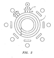
- UV lamps are arranged around the surface of the photosensitive printing sleeve such that the entire surface of the printing sleeve is simultaneously subjected to actinic radiation to cure the relief image.
- the UV-lamps (6) are generally selected so that the length of the lamps is approximately the length of the cylindrical printing sleeve to provide adequate exposure of the entire surface of the printing sleeve.
- one or more sources of actinic radiation (6) are used and the photosensitive printing element (1) is rotated about its axis to expose the entire surface of the photosensitive element to actinic radiation from the source(s) of actinic radiation (6).
- the UV-lamp is generally selected so that the length of the lamp is approximately the length of the cylindrical printing sleeve to provide adequate exposure of the entire surface of the printing sleeve.
- the quality of the relief image is improved by collimating the one or more sources of actinic radiation.
- Collimation is a term used to describe the quality of a light source.
- To "collimate" means to make straight. In terms of the instant application, the term refers to the light rays striking the photosensitive printing sleeve at an angle that is substantially perpendicular to the surface of the photosensitive printing element at the point of impact.
- One suitable collimator is described in U.S. Patent No. 6,245,487 to Randall . Other suitable collimators would also be known to those skilled in the art.
- the UV lamps may be collimated by positioning at least one collimator (7) between each of the UV-lamps (6) and the photopolymerizable printing sleeve (1).
- the collimator (7) generally has first and second opposing major faces and comprises at least one cell that extends from the first major face to the second major face.
- the collimator (7) is defined by at least one surface that substantially absorbs actinic radiation incident upon the surface. During operation, actinic radiation passes first through the collimator (7) before reaching the photopolymerizable printing sleeve (1).
- the collimators of the present invention contain at least one cell and, preferably, a plurality of cells. These cells are defined by walls that absorb radiation emitted from an actinic radiation source at severely oblique angles to the plane of the negative. The cell walls preferably absorb this radiation such that the remaining rays pass through the cells of the collimator in a direction substantially parallel to the negative plane. Radiation that is emitted by the source at more moderate oblique angles, i.e., radiation that does not contact the cell walls, is unaltered by passage through the collimator.
- the surfaces of the cell walls are substantially non-reflective. Non-reflective characteristics can be imparted to the cell walls in a number of ways.
- the cell walls can be (or coated to be) a color that is radiation absorbing, i.e., black.
- the cell walls can be textured, or both coated and textured with a material that inherently absorbs radiation.
Landscapes
- Physics & Mathematics (AREA)
- General Physics & Mathematics (AREA)
- Photosensitive Polymer And Photoresist Processing (AREA)
- Printing Plates And Materials Therefor (AREA)
- Manufacture Or Reproduction Of Printing Formes (AREA)
Claims (10)
- Verfahren zur Herstellung einer hohlen zylindrischen Druckhülse, wobei das Verfahren aufweist :a) Bereitstellen eines photoempfindlichen Druckelements, aufweisend:i) eine hohle zylindrische Stützschicht, wobei die hohle zylindrische Stützschicht eine aktinische Strahlung absorbierende Zusammensetzung aufweist, welche gleichmäßig durchwegs verteilt ist;ii) mindestens eine Schicht von photopolymerisierbarem Material, welche an der hohlen zylindrischen Stützschicht angelagert ist; undiii) eine Abdeckschicht auf der mindestens einen Schicht von photopolymerisierbarem Material, welche Strahlung bei einer Wellenlänge absorbiert, welche verwendet wird, um die Schicht von photopolymerisierbarem Material zu polymerisieren;b) Entfernen von Teilen der Abdeckschicht, indem die Abdeckschicht Laserstrahlung bei einer ausgewählten Wellenlänge und Stärke ausgesetzt wird;c) Aussetzen der Schicht von photopolymerisierbarem Material aktinischer Strahlung durch die hohle zylindrische Stützschicht, um eine Bodenschicht von polymerisiertem Material zu erzeugen;d) Aussetzen der Oberfläche der zylindrischen Hülse mindestens einer Quelle von aktinischer Strahlung, um die Teile der Schicht von photopolymerisierbarem Material zu polymerisieren, welche während Laserablation der Abdeckschicht offengelegt wurden, wobei die mindestens eine Quelle von aktinischer Strahlung eine oder mehrere kollimierte Quellen aktinischer Strahlung aufweist; unde) Entwickeln des photoempfindlichen Druckelements, um die Abdeckschicht zu entfernen und die nichtpolymerisierten Teile der Schicht von photopolymerisierbarem Material, um ein Reliefbild an der Oberfläche des photoempfindlichen Druckelements zu erzeugen;wobei aktinische Strahlung von der mindestens einen Quelle von aktinischer Strahlung auf das photopolymerisierbare Material in einem Winkel auftrifft, welcher im Wesentlichen senkrecht zu der Oberfläche am Auftreffpunkt ist.
- Verfahren nach Anspruch 1, wobei die hohle zylindrische Basisschicht, welche ein aktinische Strahlung absorbierendes Material aufweist, welches gleichmäßig durchwegs verteilt ist, zwischen 85 und 95 Prozent aktinischer Strahlung absorbiert.
- Verfahren nach Anspruch 1, wobei die hohle zylindrische Stützschicht Polyethylen-Terephthalat ist.
- Verfahren nach Anspruch 1, wobei die Abdeckschicht eine Strahlung absorbierende Zusammensetzung und einen Binder aufweist.
- Verfahren nach Anspruch 4, wobei die Strahlung absorbierende Zusammensetzung ausgewählt ist aus der Gruppe bestehend aus dunklen anorganischen Pigmenten, Ruß und Graphit.
- Verfahren nach Anspruch 1, wobei die mindestens eine Quelle von aktinischer Strahlung kollimiert ist.
- Verfahren nach Anspruch 1, wobei die mindestens eine Quelle von aktinischer Strahlung Ultraviolettlampen aufweist, welche um das photoempfindliche Druckelement herum angeordnet sind, wobei die Ultraviolettlampen die gesamte Oberfläche des photoempfindlichen Druckelements gleichzeitig aktinischer Strahlung aussetzen.
- Verfahren nach Anspruch 7, wobei die Ultraviolettlampen kollimiert sind durch Positionieren mindestens eines Kollimators zwischen den Ultraviolettlampen und dem photopolymerisierbaren Druckelement, wobei der mindestens eine Kollimator erste und zweite gegenüberliegende Hauptflächen aufweist und mindestens eine Zelle aufweist, welche sich von der ersten Hauptfläche zu der zweiten Hauptfläche erstreckt, wobei der mindestens eine Kollimator definiert ist durch mindestens eine Oberfläche, welche im Wesentlichen aktinische Strahlung, welche auf die Oberfläche auftrifft, absorbiert und wobei aktinische Strahlung durch den Kollimator vor dem Erreichen der photopolymerisierbaren Druckhülse hindurch gelangt.
- Verfahren nach Anspruch 1, wobei das photoempfindliche Druckelement benachbart zu der mindestens einen Quelle von aktinischer Strahlung positioniert ist und wobei das photoempfindliche Druckelement um seine Achse rotiert wird, um die gesamte Oberfläche des photoempfindlichen Druckelements aktinischer Strahlung von der mindestens einen Quelle von aktinischer Strahlung auszusetzen.
- Verfahren nach Anspruch 9, wobei die mindestens eine Quelle von aktinischer Strahlung eine Ultraviolettlampe ist und die Ultraviolettlampe kollimiert ist durch Positionierung eines Kollimators zwischen der Ultraviolettlampe und der photopolymerisierbaren Druckhülse, wobei der Kollimator erste und zweite gegenüberliegende Hauptflächen aufweist und mindestens eine Zelle umfasst, welche sich von der ersten Hauptfläche zu der zweiten Hauptfläche erstreckt, wobei der Kollimator definiert ist durch mindestens eine Oberfläche, welche im Wesentlichen aktinische Strahlung absorbiert, welche auf die Oberfläche auftrifft und wobei aktinische Strahlung von der Ultraviolettlampe durch den Kollimator vor Erreichen der photopolymerisierbaren Druckhülse hindurch gelangt.
Applications Claiming Priority (2)
| Application Number | Priority Date | Filing Date | Title |
|---|---|---|---|
| US10/768,610 US20050170287A1 (en) | 2004-01-30 | 2004-01-30 | Photosensitive printing sleeves and method of forming the same |
| PCT/US2004/042543 WO2005076082A1 (en) | 2004-01-30 | 2004-12-20 | Photosensitive printing sleeves and method of forming the same |
Publications (3)
| Publication Number | Publication Date |
|---|---|
| EP1709488A1 EP1709488A1 (de) | 2006-10-11 |
| EP1709488A4 EP1709488A4 (de) | 2008-01-02 |
| EP1709488B1 true EP1709488B1 (de) | 2011-11-02 |
Family
ID=34807918
Family Applications (1)
| Application Number | Title | Priority Date | Filing Date |
|---|---|---|---|
| EP04814692A Expired - Lifetime EP1709488B1 (de) | 2004-01-30 | 2004-12-20 | Verfahren zur Herstellung lichtempfindlicher Druckhülsen |
Country Status (7)
| Country | Link |
|---|---|
| US (2) | US20050170287A1 (de) |
| EP (1) | EP1709488B1 (de) |
| JP (1) | JP2007519977A (de) |
| CN (1) | CN1906538A (de) |
| ES (1) | ES2378622T3 (de) |
| TW (1) | TWI316647B (de) |
| WO (1) | WO2005076082A1 (de) |
Families Citing this family (13)
| Publication number | Priority date | Publication date | Assignee | Title |
|---|---|---|---|---|
| US20050170287A1 (en) * | 2004-01-30 | 2005-08-04 | Kanga Rustom S. | Photosensitive printing sleeves and method of forming the same |
| US20050277062A1 (en) * | 2004-05-07 | 2005-12-15 | Mclean Michael E | Method of making a photopolymer sleeve blank having an integral UV transparent cushion layer for flexographic printing |
| US8505451B2 (en) * | 2004-05-07 | 2013-08-13 | Day International, Inc. | Method of making a photopolymer sleeve blank having an integral cushion layer for flexographic printing |
| US20050250043A1 (en) * | 2004-05-07 | 2005-11-10 | Mclean Michael E | Method of making a photopolymer sleeve blank for flexographic printing |
| US7081331B2 (en) * | 2004-11-12 | 2006-07-25 | Ryan Vest | Method for thermally processing photosensitive printing sleeves |
| US8252514B2 (en) | 2006-03-14 | 2012-08-28 | Day International, Inc. | Flexographic printing plate assembly |
| US8468940B2 (en) * | 2009-06-19 | 2013-06-25 | E. I. Du Pont De Nemours And Company | Apparatus and process for exposing a printing form having a cylindrical support |
| US8820234B2 (en) * | 2009-10-30 | 2014-09-02 | Esko-Graphics Imaging Gmbh | Curing of photo-curable printing plates with flat tops or round tops by variable speed exposure |
| ITMI20102096A1 (it) * | 2010-11-12 | 2012-05-13 | Carminati & Guizzardi Srl | Procedimento di realizzazione di lastre flessografiche, particolarmente per sistemi di stampa flessografica, ed un dispositivo fotoespositore. |
| US20120129097A1 (en) * | 2010-11-18 | 2012-05-24 | Jonghan Choi | Photopolymer Printing Plates with In Situ Non-Directional Floor Formed During Extrusion |
| JP2014048517A (ja) * | 2012-08-31 | 2014-03-17 | Asahi Kasei E-Materials Corp | フレキソ印刷版用構成体及びフレキソ印刷版 |
| CN104937697B (zh) * | 2013-08-01 | 2018-01-16 | Lg化学株式会社 | 曝光装置 |
| CN113703280A (zh) * | 2021-09-08 | 2021-11-26 | 深圳市龙图光电有限公司 | 曝光方法以及曝光装置 |
Family Cites Families (79)
| Publication number | Priority date | Publication date | Assignee | Title |
|---|---|---|---|---|
| US1986052A (en) * | 1933-08-24 | 1935-01-01 | Ferree Clarence Errol | Variable intensity lamp |
| BE525225A (de) * | 1951-08-20 | |||
| BE627652A (de) * | 1962-01-29 | |||
| US3264103A (en) * | 1962-06-27 | 1966-08-02 | Du Pont | Photopolymerizable relief printing plates developed by dry thermal transfer |
| US3217625A (en) * | 1963-07-05 | 1965-11-16 | Tecnifax Corp | High resolution reproduction apparatus |
| GB1251232A (de) * | 1967-10-12 | 1971-10-27 | ||
| US3619601A (en) * | 1968-10-28 | 1971-11-09 | Grace W R & Co | Method and apparatus for posterior photocuring |
| US3645178A (en) * | 1969-03-27 | 1972-02-29 | Ibm | Apparatus for exposing photoresist in cylinders |
| US3645179A (en) * | 1969-03-27 | 1972-02-29 | Ibm | Apparatus for exposing photoresist in cylinders |
| CA1099435A (en) * | 1971-04-01 | 1981-04-14 | Gwendyline Y. Y. T. Chen | Photosensitive block copolymer composition and elements |
| US4323636A (en) * | 1971-04-01 | 1982-04-06 | E. I. Du Pont De Nemours And Company | Photosensitive block copolymer composition and elements |
| US3867153A (en) * | 1972-09-11 | 1975-02-18 | Du Pont | Photohardenable element |
| US4045231A (en) * | 1975-03-15 | 1977-08-30 | Tokyo Ohka Kogyo Kabushiki Kaisha | Photosensitive resin composition for flexographic printing plates |
| US4656942A (en) * | 1977-12-27 | 1987-04-14 | Stork Brabant B.V. | Printing apparatus utilizing flexible metal sleeves as ink transfer means |
| JPS54130205A (en) * | 1978-03-29 | 1979-10-09 | Nippon Paint Co Ltd | Method and device for making photosensitive resin cylinder |
| DE2942183A1 (de) * | 1979-10-18 | 1981-05-07 | Basf Ag, 6700 Ludwigshafen | Fotopolymerisierbare gemische und elemente daraus |
| US4264705A (en) * | 1979-12-26 | 1981-04-28 | Uniroyal, Inc. | Multilayered elastomeric printing plate |
| NL8003895A (nl) * | 1980-07-04 | 1982-02-01 | Stork Screens Bv | Huls voor een drukcilinder alsmede werkwijze en inrichting voor het vervaardigen van een dergelijke huls. |
| US4423135A (en) * | 1981-01-28 | 1983-12-27 | E. I. Du Pont De Nemours & Co. | Preparation of photosensitive block copolymer elements |
| US4427759A (en) * | 1982-01-21 | 1984-01-24 | E. I. Du Pont De Nemours And Company | Process for preparing an overcoated photopolymer printing plate |
| US4503769A (en) * | 1982-06-21 | 1985-03-12 | Armotek Industries, Inc. | Metal coated thin wall plastic printing cylinder for rotogravure printing |
| NL8204751A (nl) * | 1982-12-08 | 1984-07-02 | Stork Screens Bv | Werkwijze voor het vervaardigen van een drukhuls. |
| US4622088A (en) * | 1984-12-18 | 1986-11-11 | E. I. Du Pont De Nemours And Company | Process for preparing photopolymer flexographic element with melt extrusion coated elastomeric surface layer |
| NL8500992A (nl) * | 1985-04-03 | 1986-11-03 | Stork Screens Bv | Werkwijze voor het vormen van een gedessineerde fotopolymeerbekleding op een drukwals alsmede drukwals met gedessineerde fotopolymeerbekleding. |
| US4868090A (en) * | 1985-08-24 | 1989-09-19 | Atsushi Kitamura | Methods for the manufacture of cylindrical photosensitive resin structures and cylindrical printing plates |
| JPH0675191B2 (ja) * | 1985-09-30 | 1994-09-21 | 北村 篤識 | 筒状印刷版の製造法 |
| DK600285D0 (da) * | 1985-12-20 | 1985-12-20 | Jens Erik Sattrup | Fremgangsmaade til fremstilling af en dybtrykcylinder |
| DE3600774C1 (de) * | 1986-01-14 | 1987-05-07 | Du Pont Deutschland | Verfahren zum Verkleben von photopolymerisierbaren Druckplatten oder Druckformen fuer den Flexodruck |
| NL8601119A (nl) * | 1986-05-01 | 1987-12-01 | Stork Screens Bv | Werkwijze voor het vervaardigen van een bekleed voortbrengsel, onder toepassing van deze werkwijze verkregen dunwandige beklede cylinder, en een dergelijke cylinder omvattende inktoverdrachtswals. |
| JPH0797215B2 (ja) * | 1986-09-20 | 1995-10-18 | 日本電信電話株式会社 | 三層レジスト用中間層材料およびパタ−ン形成方法 |
| DE3704693A1 (de) * | 1987-02-14 | 1988-08-25 | Basf Ag | Verfahren zum nahtlosen und haftfesten verbinden der end- und/oder seitenbereiche von lichtempfindlichen schichten sowie verwendung der so verbundenen lichtempfindlichen schichten fuer die herstellung von druckformen |
| NL8800781A (nl) * | 1988-03-28 | 1989-10-16 | Stork Screens Bv | Werkwijze voor het aanbrengen van een huls op een walskern en walskern geschikt voor bedoelde werkwijze. |
| US4903597A (en) * | 1988-10-24 | 1990-02-27 | Lavalley Industries, Inc. | Printing sleeves and methods for mounting and dismounting |
| DE4004512A1 (de) * | 1990-02-14 | 1991-08-22 | Hoechst Ag | Verfahren zur herstellung von photopolymerplatten |
| US5175072A (en) * | 1990-07-26 | 1992-12-29 | Minnesota Mining And Manufacturing Company | Flexographic printing plate process |
| GB9016488D0 (en) * | 1990-07-27 | 1990-09-12 | Zed Instr Ltd | Printing cylinder |
| DE69129567T2 (de) * | 1990-07-31 | 1998-12-24 | Minnesota Mining And Mfg. Co., Saint Paul, Minn. | Vorrichtung für die Herstellung von flexographischen Druckplatten |
| US5223375A (en) * | 1991-07-15 | 1993-06-29 | W. R. Grace & Co.-Conn. | Flexographic printing plate comprising photosensitive elastomer polymer composition |
| WO1993003081A1 (en) * | 1991-07-31 | 1993-02-18 | E.I. Du Pont De Nemours And Company | Coating compositions based on graft polymers |
| US5262275A (en) * | 1992-08-07 | 1993-11-16 | E. I. Du Pont De Nemours And Company | Flexographic printing element having an IR ablatable layer and process for making a flexographic printing plate |
| US5719009A (en) * | 1992-08-07 | 1998-02-17 | E. I. Du Pont De Nemours And Company | Laser ablatable photosensitive elements utilized to make flexographic printing plates |
| DE9305806U1 (de) * | 1993-04-19 | 1993-06-09 | Hoechst Ag, 6230 Frankfurt | Druckwalze mit einer Hülse aus thermisch gewickelten faserverstärkten Thermoplasten und einer plasmagespritzten Kupfer- oder Kupferlegierungsbeschichtung |
| US5301610A (en) * | 1993-04-30 | 1994-04-12 | E. I. Du Pont De Nemours And Company | Method and apparatus for making spiral wound sleeves for printing cylinders and product thereof |
| DE4339010C2 (de) * | 1993-06-25 | 2000-05-18 | Pt Sub Inc | Photohärtbares Erzeugnis für Druckplatten |
| US6756181B2 (en) * | 1993-06-25 | 2004-06-29 | Polyfibron Technologies, Inc. | Laser imaged printing plates |
| WO1995028820A1 (en) * | 1994-04-15 | 1995-10-26 | Philips Electronics N.V. | Method of manufacturing a device, by irradiating some parts of the surface of the device directly through a mask, and other parts indirectly through the mask and via a reflecting surface, thereby producing a pattern |
| DE4432816A1 (de) * | 1994-09-15 | 1996-03-21 | Roland Man Druckmasch | Druckwalze für den kanallosen Druck |
| CA2207591A1 (en) * | 1994-12-13 | 1996-06-20 | Douglas R. Leach | Photosensitive compositions and clean running photopolymer printing plates therefrom |
| US5654125A (en) * | 1995-05-01 | 1997-08-05 | E. I. Du Pont De Nemours And Company | Laser apparatus and process of use |
| US6238837B1 (en) * | 1995-05-01 | 2001-05-29 | E.I. Du Pont De Nemours And Company | Flexographic element having an infrared ablatable layer |
| US5798019A (en) * | 1995-09-29 | 1998-08-25 | E. I. Du Pont De Nemours And Company | Methods and apparatus for forming cylindrical photosensitive elements |
| EP0785474A1 (de) * | 1996-01-16 | 1997-07-23 | Schablonentechnik Kufstein Aktiengesellschaft | Verfahren und Vorrichtung zur Herstellung einer Flexodruckschablone |
| US5840386A (en) * | 1996-02-22 | 1998-11-24 | Praxair S.T. Technology, Inc. | Sleeve for a liquid transfer roll and method for producing it |
| US5819657A (en) * | 1996-03-11 | 1998-10-13 | Ermino Rossini, Spa | Air carrier spacer sleeve for a printing cylinder |
| US5888697A (en) * | 1996-07-03 | 1999-03-30 | E. I. Du Pont De Nemours And Company | Flexographic printing element having a powder layer |
| US6312872B1 (en) * | 1997-10-24 | 2001-11-06 | Macdermid Graphic Arts | Composite relief image printing plates |
| US6143451A (en) * | 1996-11-26 | 2000-11-07 | E. I. Du Pont De Nemours And Company | Imaged laserable assemblages and associated processes with high speed and durable image-transfer characteristics for laser-induced thermal transfer |
| EP0897796B1 (de) * | 1997-08-18 | 2000-04-26 | Schablonentechnik Kufstein Aktiengesellschaft | Verfahren zur Herstellung einer Siebdruckschablone und hierfür geeignete Vorrichtung |
| DE29802468U1 (de) * | 1998-02-13 | 1998-04-16 | Basf Drucksysteme Gmbh | Druckformkörper in Zylinderform |
| JP3373147B2 (ja) * | 1998-02-23 | 2003-02-04 | シャープ株式会社 | フォトレジスト膜及びそのパターン形成方法 |
| US6214522B1 (en) * | 1998-08-28 | 2001-04-10 | Macdermid, Incorporated | Photosensitive resin composition useful in fabricating printing plates |
| US6180325B1 (en) * | 1999-06-23 | 2001-01-30 | Creo Srl | Method for masking and exposing photosensitive printing plates |
| US6425327B1 (en) * | 1999-08-12 | 2002-07-30 | E. I. Du Pont De Nemours And Company | Method for forming a cylindrical photosensitive element |
| US6245487B1 (en) * | 1999-08-26 | 2001-06-12 | Polyfibron Technologies, Inc. | Methods for enhancing images on relief image printing plates |
| US6797454B1 (en) * | 1999-09-07 | 2004-09-28 | E. I. Du Pont De Nemours And Company | Method and apparatus for thermal processing a photosensitive element |
| US6413699B1 (en) * | 1999-10-11 | 2002-07-02 | Macdermid Graphic Arts, Inc. | UV-absorbing support layers and flexographic printing elements comprising same |
| FR2803245B1 (fr) * | 1999-12-31 | 2002-12-20 | Rollin Sa | Plaque compressible pour impression flexographique et procede d'obtention |
| US6367381B1 (en) * | 2000-02-22 | 2002-04-09 | Polyfibron Technologies, Inc. | Laser imaged printing plates comprising a multi-layer slip film |
| EP1154322A1 (de) * | 2000-05-10 | 2001-11-14 | Erminio Rossini S.P.A. | Photopolymerzusammensetzung und seine Verwendung zur Herstellung von Flexodruckzylindern oder Flexodruckzylinder-Hülsen mit einer nahtlosen lichtempfindlichen Schicht |
| EP1282838B1 (de) * | 2000-05-17 | 2007-01-03 | E.I. Dupont De Nemours And Company | Verfahren zur herstellung einer flexodruckplatte |
| EP1158365B1 (de) * | 2000-05-18 | 2011-12-21 | Du Pont De Nemours (Deutschland) Gmbh | Verfahren und Gerät zum Beschichten von zylindrischen Druckformen |
| DE10109041A1 (de) * | 2001-02-24 | 2002-09-05 | Heidelberger Druckmasch Ag | Verfahren und Mehrstrahl-Abtastvorrichtung zur Ablation von Flexo-Druckplatten durch Lasergravur |
| US6773859B2 (en) * | 2001-03-06 | 2004-08-10 | E. I. Du Pont De Nemours And Company | Process for making a flexographic printing plate and a photosensitive element for use in the process |
| US6664999B2 (en) * | 2001-12-06 | 2003-12-16 | Fuji Photo Film Co., Ltd. | Image-recording device and method |
| US6640711B2 (en) * | 2002-01-15 | 2003-11-04 | Michael A. Smoot | Bridge mandrel for use as a repeat builder in a printing machine |
| US6703095B2 (en) * | 2002-02-19 | 2004-03-09 | Day International, Inc. | Thin-walled reinforced sleeve with integral compressible layer |
| US6766740B1 (en) * | 2002-02-21 | 2004-07-27 | Precision Rubber Plate Co., Inc. | Apparatus and method using a UV light collimator to expose a photopolymer plate |
| US6966259B2 (en) * | 2004-01-09 | 2005-11-22 | Kanga Rustom S | Printing sleeve with an integrated printing surface |
| US20050170287A1 (en) * | 2004-01-30 | 2005-08-04 | Kanga Rustom S. | Photosensitive printing sleeves and method of forming the same |
-
2004
- 2004-01-30 US US10/768,610 patent/US20050170287A1/en not_active Abandoned
- 2004-12-20 CN CNA2004800407385A patent/CN1906538A/zh active Pending
- 2004-12-20 ES ES04814692T patent/ES2378622T3/es not_active Expired - Lifetime
- 2004-12-20 WO PCT/US2004/042543 patent/WO2005076082A1/en not_active Ceased
- 2004-12-20 US US10/586,414 patent/US20070160934A1/en not_active Abandoned
- 2004-12-20 JP JP2006551080A patent/JP2007519977A/ja active Pending
- 2004-12-20 EP EP04814692A patent/EP1709488B1/de not_active Expired - Lifetime
-
2005
- 2005-01-12 TW TW094100839A patent/TWI316647B/zh not_active IP Right Cessation
Also Published As
| Publication number | Publication date |
|---|---|
| EP1709488A4 (de) | 2008-01-02 |
| TW200538882A (en) | 2005-12-01 |
| US20050170287A1 (en) | 2005-08-04 |
| US20070160934A1 (en) | 2007-07-12 |
| CN1906538A (zh) | 2007-01-31 |
| JP2007519977A (ja) | 2007-07-19 |
| ES2378622T3 (es) | 2012-04-16 |
| WO2005076082A1 (en) | 2005-08-18 |
| EP1709488A1 (de) | 2006-10-11 |
| TWI316647B (en) | 2009-11-01 |
Similar Documents
| Publication | Publication Date | Title |
|---|---|---|
| US6413699B1 (en) | UV-absorbing support layers and flexographic printing elements comprising same | |
| US8524442B1 (en) | Integrated membrane lamination and UV exposure system and method of the same | |
| EP2997423B1 (de) | Verfahren zur verbesserung der druckleistung flexografischer druckplatten | |
| EP1709488B1 (de) | Verfahren zur Herstellung lichtempfindlicher Druckhülsen | |
| EP2359190A2 (de) | Flexografisches element und verfahren zur bildgebung | |
| ES2518990T3 (es) | Proceso de prevención de curado de borde | |
| US20250328077A1 (en) | Method of controlling imaging characteristics in flexographic relief image printing plates | |
| US7060417B2 (en) | Edge cure prevention process |
Legal Events
| Date | Code | Title | Description |
|---|---|---|---|
| PUAI | Public reference made under article 153(3) epc to a published international application that has entered the european phase |
Free format text: ORIGINAL CODE: 0009012 |
|
| 17P | Request for examination filed |
Effective date: 20060628 |
|
| AK | Designated contracting states |
Kind code of ref document: A1 Designated state(s): DE ES FR GB IT |
|
| DAX | Request for extension of the european patent (deleted) | ||
| RBV | Designated contracting states (corrected) |
Designated state(s): DE ES FR GB IT |
|
| A4 | Supplementary search report drawn up and despatched |
Effective date: 20071130 |
|
| 17Q | First examination report despatched |
Effective date: 20090730 |
|
| RTI1 | Title (correction) |
Free format text: METHOD OF FORMING PHOTOSENSITIVE PRINTING SLEEVES |
|
| GRAP | Despatch of communication of intention to grant a patent |
Free format text: ORIGINAL CODE: EPIDOSNIGR1 |
|
| GRAS | Grant fee paid |
Free format text: ORIGINAL CODE: EPIDOSNIGR3 |
|
| GRAA | (expected) grant |
Free format text: ORIGINAL CODE: 0009210 |
|
| AK | Designated contracting states |
Kind code of ref document: B1 Designated state(s): DE ES FR GB IT |
|
| REG | Reference to a national code |
Ref country code: GB Ref legal event code: FG4D |
|
| REG | Reference to a national code |
Ref country code: DE Ref legal event code: R096 Ref document number: 602004035174 Country of ref document: DE Effective date: 20120105 |
|
| REG | Reference to a national code |
Ref country code: ES Ref legal event code: FG2A Ref document number: 2378622 Country of ref document: ES Kind code of ref document: T3 Effective date: 20120416 |
|
| PLBE | No opposition filed within time limit |
Free format text: ORIGINAL CODE: 0009261 |
|
| STAA | Information on the status of an ep patent application or granted ep patent |
Free format text: STATUS: NO OPPOSITION FILED WITHIN TIME LIMIT |
|
| 26N | No opposition filed |
Effective date: 20120803 |
|
| REG | Reference to a national code |
Ref country code: DE Ref legal event code: R097 Ref document number: 602004035174 Country of ref document: DE Effective date: 20120803 |
|
| REG | Reference to a national code |
Ref country code: FR Ref legal event code: PLFP Year of fee payment: 12 |
|
| REG | Reference to a national code |
Ref country code: FR Ref legal event code: PLFP Year of fee payment: 13 |
|
| PG25 | Lapsed in a contracting state [announced via postgrant information from national office to epo] |
Ref country code: IT Free format text: LAPSE BECAUSE OF NON-PAYMENT OF DUE FEES Effective date: 20151220 |
|
| PG25 | Lapsed in a contracting state [announced via postgrant information from national office to epo] |
Ref country code: IT Free format text: LAPSE BECAUSE OF NON-PAYMENT OF DUE FEES Effective date: 20151220 |
|
| PGRI | Patent reinstated in contracting state [announced from national office to epo] |
Ref country code: IT Effective date: 20170710 |
|
| REG | Reference to a national code |
Ref country code: FR Ref legal event code: PLFP Year of fee payment: 14 |
|
| PGFP | Annual fee paid to national office [announced via postgrant information from national office to epo] |
Ref country code: FR Payment date: 20171227 Year of fee payment: 14 |
|
| PGFP | Annual fee paid to national office [announced via postgrant information from national office to epo] |
Ref country code: GB Payment date: 20171227 Year of fee payment: 14 |
|
| PGFP | Annual fee paid to national office [announced via postgrant information from national office to epo] |
Ref country code: DE Payment date: 20171229 Year of fee payment: 14 Ref country code: ES Payment date: 20180102 Year of fee payment: 14 |
|
| PGFP | Annual fee paid to national office [announced via postgrant information from national office to epo] |
Ref country code: IT Payment date: 20171221 Year of fee payment: 14 |
|
| REG | Reference to a national code |
Ref country code: DE Ref legal event code: R119 Ref document number: 602004035174 Country of ref document: DE |
|
| GBPC | Gb: european patent ceased through non-payment of renewal fee |
Effective date: 20181220 |
|
| PG25 | Lapsed in a contracting state [announced via postgrant information from national office to epo] |
Ref country code: FR Free format text: LAPSE BECAUSE OF NON-PAYMENT OF DUE FEES Effective date: 20181231 Ref country code: IT Free format text: LAPSE BECAUSE OF NON-PAYMENT OF DUE FEES Effective date: 20181220 Ref country code: DE Free format text: LAPSE BECAUSE OF NON-PAYMENT OF DUE FEES Effective date: 20190702 |
|
| PG25 | Lapsed in a contracting state [announced via postgrant information from national office to epo] |
Ref country code: GB Free format text: LAPSE BECAUSE OF NON-PAYMENT OF DUE FEES Effective date: 20181220 |
|
| REG | Reference to a national code |
Ref country code: ES Ref legal event code: FD2A Effective date: 20200203 |
|
| PG25 | Lapsed in a contracting state [announced via postgrant information from national office to epo] |
Ref country code: ES Free format text: LAPSE BECAUSE OF NON-PAYMENT OF DUE FEES Effective date: 20181221 |