EP1708656B1 - Magenband - Google Patents
Magenband Download PDFInfo
- Publication number
- EP1708656B1 EP1708656B1 EP05717418.7A EP05717418A EP1708656B1 EP 1708656 B1 EP1708656 B1 EP 1708656B1 EP 05717418 A EP05717418 A EP 05717418A EP 1708656 B1 EP1708656 B1 EP 1708656B1
- Authority
- EP
- European Patent Office
- Prior art keywords
- belt
- inflatable
- chamber
- gastric belt
- wall
- Prior art date
- Legal status (The legal status is an assumption and is not a legal conclusion. Google has not performed a legal analysis and makes no representation as to the accuracy of the status listed.)
- Active
Links
- 230000002496 gastric effect Effects 0.000 title claims description 55
- 239000000463 material Substances 0.000 claims description 7
- 239000012530 fluid Substances 0.000 claims description 5
- 241000218657 Picea Species 0.000 claims 1
- 210000002784 stomach Anatomy 0.000 description 18
- 230000003287 optical effect Effects 0.000 description 6
- 210000003238 esophagus Anatomy 0.000 description 5
- 230000001788 irregular Effects 0.000 description 5
- 208000031968 Cadaver Diseases 0.000 description 4
- 206010061218 Inflammation Diseases 0.000 description 4
- 238000002513 implantation Methods 0.000 description 4
- 230000004054 inflammatory process Effects 0.000 description 4
- 239000007924 injection Substances 0.000 description 3
- 238000002347 injection Methods 0.000 description 3
- 239000004809 Teflon Substances 0.000 description 2
- 229920006362 Teflon® Polymers 0.000 description 2
- 238000000034 method Methods 0.000 description 2
- 238000005096 rolling process Methods 0.000 description 2
- 239000007787 solid Substances 0.000 description 2
- 230000008961 swelling Effects 0.000 description 2
- 229920004934 Dacron® Polymers 0.000 description 1
- 208000027418 Wounds and injury Diseases 0.000 description 1
- 230000003187 abdominal effect Effects 0.000 description 1
- 239000000560 biocompatible material Substances 0.000 description 1
- 230000015572 biosynthetic process Effects 0.000 description 1
- 239000011248 coating agent Substances 0.000 description 1
- 238000000576 coating method Methods 0.000 description 1
- 239000000470 constituent Substances 0.000 description 1
- 230000006378 damage Effects 0.000 description 1
- 230000006866 deterioration Effects 0.000 description 1
- 238000006073 displacement reaction Methods 0.000 description 1
- 230000003628 erosive effect Effects 0.000 description 1
- 239000004744 fabric Substances 0.000 description 1
- -1 for example Substances 0.000 description 1
- 208000014674 injury Diseases 0.000 description 1
- 238000003780 insertion Methods 0.000 description 1
- 230000037431 insertion Effects 0.000 description 1
- 238000002357 laparoscopic surgery Methods 0.000 description 1
- 239000012528 membrane Substances 0.000 description 1
- 238000012986 modification Methods 0.000 description 1
- 230000004048 modification Effects 0.000 description 1
- 230000017074 necrotic cell death Effects 0.000 description 1
- 239000005416 organic matter Substances 0.000 description 1
- 239000002504 physiological saline solution Substances 0.000 description 1
- 239000005020 polyethylene terephthalate Substances 0.000 description 1
- 229920001296 polysiloxane Polymers 0.000 description 1
- 230000002787 reinforcement Effects 0.000 description 1
- 238000007789 sealing Methods 0.000 description 1
- 238000001356 surgical procedure Methods 0.000 description 1
- 230000001225 therapeutic effect Effects 0.000 description 1
Images


Classifications
-
- A—HUMAN NECESSITIES
- A61—MEDICAL OR VETERINARY SCIENCE; HYGIENE
- A61F—FILTERS IMPLANTABLE INTO BLOOD VESSELS; PROSTHESES; DEVICES PROVIDING PATENCY TO, OR PREVENTING COLLAPSING OF, TUBULAR STRUCTURES OF THE BODY, e.g. STENTS; ORTHOPAEDIC, NURSING OR CONTRACEPTIVE DEVICES; FOMENTATION; TREATMENT OR PROTECTION OF EYES OR EARS; BANDAGES, DRESSINGS OR ABSORBENT PADS; FIRST-AID KITS
- A61F5/00—Orthopaedic methods or devices for non-surgical treatment of bones or joints; Nursing devices; Anti-rape devices
- A61F5/0003—Apparatus for the treatment of obesity; Anti-eating devices
- A61F5/0013—Implantable devices or invasive measures
- A61F5/005—Gastric bands
- A61F5/0066—Closing devices for gastric bands
-
- A—HUMAN NECESSITIES
- A61—MEDICAL OR VETERINARY SCIENCE; HYGIENE
- A61F—FILTERS IMPLANTABLE INTO BLOOD VESSELS; PROSTHESES; DEVICES PROVIDING PATENCY TO, OR PREVENTING COLLAPSING OF, TUBULAR STRUCTURES OF THE BODY, e.g. STENTS; ORTHOPAEDIC, NURSING OR CONTRACEPTIVE DEVICES; FOMENTATION; TREATMENT OR PROTECTION OF EYES OR EARS; BANDAGES, DRESSINGS OR ABSORBENT PADS; FIRST-AID KITS
- A61F5/00—Orthopaedic methods or devices for non-surgical treatment of bones or joints; Nursing devices; Anti-rape devices
- A61F5/0003—Apparatus for the treatment of obesity; Anti-eating devices
- A61F5/0013—Implantable devices or invasive measures
- A61F5/005—Gastric bands
Definitions
- the invention relates to the technical field of devices intended to be implanted at the level of the connection zone between the abdominal part of the esophagus and the stomach, in order to create a local restriction allowing a control of the quantity of food ingested by the patient carrying the device.
- the inflatable gastric band comprises an elongate flat tubular body of flexible material which is at least partly elastically deformable and which defines an inflatable airtight chamber for presenting a working face intended to be placed in contact with the stomach and a back opposite of the working side.
- the demand WO 00/00108 discloses, furthermore, a gastric band according to the preamble of claim 1.
- the gastric band also comprises connecting means equipping the ends of the tubular body and for closing the gastric belt in the form of a ring, the working face being, of course , facing inwards.
- the gastric band also comprises an inflation catheter sealingly connected to the inflatable chamber and intended to be connected to inflation means.
- the inflation means may be, for example, constituted by a housing provided with a self-sealing membrane which can be pierced by a syringe needle or the like, by means of which an injection or a sample of fluid, such as, for example, For example, but not necessarily, physiological saline can be performed to control the swelling of the chamber and thus the dimensions of the stomach constriction achieved by means of the inflatable gastric band.
- the tubular body and the inflatable chamber are made to form, after closure of the belt and inflation of the latter, a ring of regular section.
- this inflatable gastric band is characterized in that the wall of the chamber, forming the working face, has, in a deflated state of the belt, a length greater than or equal to that of the wall of the chamber forming the back, so that, when closing the ring belt and after inflation, the wall of the chamber, constituting the working face, forms folds, each fold corresponding to an area where the working face is folded or folded locally on itself, so that the regions of the working face adjacent to the fold and located on either side of the fold are in contact.
- This feature of the invention then allows the formation of folds during the inflation of the belt, so that the inside of said belt does not have the regular shape of a ring but, instead, a star shape or irregular hypocycloid.
- These folds are formed randomly and not predetermined, depending on the shape, movements and compressive strength of the stomach wall.
- the folds are likely to move during use of the belt, so that the pressure points on the stomach wall also move, avoiding necrosis or local inflammation.
- the inventors had the merit of highlighting the fact that such an irregular shape during inflation ensures a better stability of the inflatable gastric band and, contrary to popular belief, the zones of pinching that it is likely to create at the outer wall of the esophagus or stomach do not increase erosion or inflammation phenomena of the latter.
- This advantageous characteristic of the invention is certainly due to the fact that the inflation fluid flows from one compartment, defined by the folds, to the other, ensuring a balancing of the inflation pressure and therefore a better distribution of applied forces. to the stomach.
- the inflatable gastric band is made in such a way that its tubular body presents, in a deflated state of the chamber and when the belt is not closed, a substantially flat shape, without pre-conformation.
- the inflatable gastric band In this state, which could then be called rest, the inflatable gastric band has a substantially rectangular parallelepiped shape, apart from the connecting means, the walls of the inflatable chamber, in relation to the working face and the back, being substantially flat and parallel.
- the internal face of the wall of the chamber comprises at least one longitudinal direction groove for defining an internal channel for circulation of the inflation fluid at the level or folds formed.
- the longitudinal groove does not necessarily extend over the entire length of the inflatable chamber, but over at least part of this length and, for example but not exclusively, in a central region of the chamber and on a length greater than or equal to half the length of the inflatable chamber.
- the inner face of the wall of the inflatable chamber comprises at least one series of parallel longitudinal grooves.
- this groove or series of grooves can be made anywhere in the wall of the inflatable chamber.
- the longitudinal groove or grooves will be arranged on the inner face of the inflatable chamber corresponding to the back of the belt.
- the inner face of the inflatable chamber corresponding to the back of the belt, then comprises two sets of parallel longitudinal grooves, each series being located near an edge of the back of the belt.
- the wall of the chamber forming the working face comprises means for locally limiting the elasticity of the wall.
- the means of local limitation of the elasticity occupy a median longitudinal region of the working face, so that, during the swelling of the belt, the longitudinal edges of the working face expand more than the middle region of said working face.
- the means for locally limiting the elasticity are adapted so that the radius of curvature of the median region of the working face during the inflation of the belt is, as far as possible, greater than the radius of curvature of the lateral regions. .
- the means for locally limiting the elasticity of the wall of the inflatable chamber may be made in any suitable manner, such as, for example, in the form of inserts, preferably but not necessarily, elastically deformable and fixed or inserted in the wall of the inflatable chamber.
- the means for locally limiting the elasticity comprise a local extra thickness of the wall of the chamber constituting the working face of the belt.
- each longitudinal edge of the inflation chamber is preferably, but not necessarily, located at a distance from the corresponding longitudinal edge of the body of the gastric band.
- each longitudinal edge of the inflatable chamber is then located at a distance from the corresponding longitudinal edge of the body of the belt, between 0.50 mm and 2.50 mm and, preferably, between 0 , 65 mm and 0.90 mm.
- the wall of the inflatable chamber forming the back of the belt, comprises at least one flexible longitudinal armature inextensible, so as to promote, when the belt is closed in a ring and during inflation of the chamber, a centripetal deformation of the inflatable chamber.
- the inextensible frame is then completely surrounded by the material constituting the body of the belt.
- the belt is molded in a single injection to form a single piece around the inextensible frame, with no other inserts that plugs at the injection points and, optionally, the constituent elements of the connecting means for closing ring of the belt.
- the connecting tail comprises at least one anti-return locking means intended to cooperate with the arch.
- the non-return locking means can be made in any appropriate manner.
- the locking means comprise at least one fir or lanceolate conformation.
- the hoop is arranged on the back of the belt, so as to avoid the risk of injury to the esophageal or stomach wall.
- the connecting means comprise at least two aligned arcs.
- the bow located closest to the free end of the body, then has a flared shape towards the free end of the belt and converging towards the second ring, so as to ensure the guiding of the catheter to the second hoop during the closing procedure of the belt.
- the width of the arch is then greater than 6 mm.
- the ring closest to the free end is located at a distance from the free end of less than 5 mm and, preferably, less than 3 mm, this distance being measured between a transverse plane passing through the top of the bow at its nearest portion of the free end and a parallel plane passing through this free end.
- the internal face of the arch has pins or striations parallel to the longitudinal axis of the body and in the direction of introduction of the catheter and the locking tail, so as to reduce friction during passage of the catheter and the tail.
- the latter is preferably, but not necessarily, covered with a low friction product, such as, for example, Teflon.
- At least one end of the inflatable chamber is located at a distance from the corresponding end of the body to define a reinforced end gripping.
- the end of the inflatable chamber is then located at a distance from the corresponding end of the body greater than 5 mm and, preferably, greater than 7 mm and, more preferably, at a distance between 7 mm and 15 mm, 10 mm being an advantageous compromise. It is thus provided a full grip end.
- the end reinforcement is obtained by adopting, in the end zone, between the three sides of the inflatable chamber and the corresponding edges of the body of the strip, a distance greater than that adopted for the rest of the band.
- this distance, in the end zone will be greater than 0.75 mm and, more preferably, between 0.75 mm and 2.50 mm, a distance of between 1, 50 mm and 2.50 mm offering a good compromise.
- the wall of the inflatable chamber is reinforced near the free end of the body of the belt and has, for this purpose, a local extra thickness in this region.
- the belt comprises means for optical identification of the back and / or the working face of the body.
- the locating means comprise optical signs affixed to the back of the belt, as well as to the corresponding face of the catheter.
- the belt comprises means of optical indication of the direction of the free end of the catheter and / or the free end of the body of the belt.
- these optical indication means comprise arrows or triangles, one point of which is directed towards the free end of the catheter.
- Such means of identification and / or optical indication then facilitate the work of the surgeon in the context of a scleral implantation.
- the free end of the catheter located opposite the body of the belt, is closed by means of a frustoconical plug which, on the one hand, prevents the introduction of organic matter, in the catheter during the introduction of the belt and, secondly, facilitates the introduction of the catheter into the arch or arches constituting the connecting means.
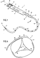
- a gastric belt according to the invention illustrated in Fig. 1 to 3 and generally designated by the reference 1, comprises a tubular body 2 which defines at least one inflatable airtight chamber 3.
- the body 2 has, in elevation in plan view, a generally rectangular shape, which corresponds to to a preferred embodiment, but not the only form that can be adopted for the body 2.
- the body 2 has a generally flat shape and a transverse cross section, as more particularly illustrated in FIG. Fig. 3 , substantially rectangular, the inflatable chamber 3 having a cross section of general shape also forming a rectangle.
- the gastric band 1 then has a back 4 and a working face 5, intended to come into contact with the esophageal or stomach area, at which the belt will be placed, as will be apparent in the following.
- the belt 1 also comprises connecting means 10 and 11 fitted to both ends of the belt.
- the connecting means 10 and 11 may be made in any suitable manner.
- the connecting means 10 comprise, first of all, at a first end 12 of the inflation body 2 , a connecting tail 13, of a catheter 14, to the inflatable chamber. 3.
- the connecting tail 13 then extends substantially in the longitudinal extension of the body 2 and has an internal channel 15 connected to the chamber 3.
- this channel 15 communicates with the internal conduit of the catheter 14.
- the connecting means 11, located at the end opposite the inflation end 12 and said free end 16, are, according to the illustrated example, constituted by at least one and, in this case, two arches 20, 21 disposed at the back 4 of the body 2 and for receiving the tail 13.
- the two hoops 20 are located at a distance from each other and the shank 13 comprises means 22 for locking or non-return purposes intended to prevent any inadvertent withdrawal of the connecting tail 13 after engagement of the latter in the arches 20, 21.
- the anti-return locking means comprise two conformations 22 fir or lanceolate, which are each intended to cooperate with a bow 20, 21 corresponding.
- the hoop 20, located closest to the free end 16 of the body 2 has a width l 20 , measured parallel to the longitudinal axis ⁇ of the body 2 and at the top of the hoop 20, greater than 5 mm.
- This arrangement of the invention thus allows the first hoop to provide guidance of the catheter 14 during the procedure of closing the belt.
- the width 20 of the first arch is greater than the width 21 of the second pole.
- the arches in order to promote this passage of the catheter and reduce, as much as possible, the efforts required for this surgical procedure, the arches have, on their inner face, a series of striations 25 that come reduce the contact area of the catheter with the corresponding arch, so as to reduce frictional forces.
- the ridges 25 extend parallel to the longitudinal axis ⁇ of the body 2 and in the insertion direction of the catheter 14.
- the first arch 20 preferably has a flared shape towards the free end of the body 2 and converging towards the second ring 21, as illustrated in FIG. Fig. 5 .
- the free end 26 of the catheter 14 is closed by a cap 27, of conical shape, which prevents the introduction of materials into the catheter channel and facilitates the introduction of the catheter into the arch 20 during closure of the belt.
- the plug 27 will be cut after closure of the belt, for the establishment of inflation means, not shown.
- the inflatable gastric band 1 may be made of any suitable biocompatible material, such as, for example, biocompatible silicone or implantable grade, which gives the body 2 the flexibility and elasticity necessary for the inflation of the chamber 3.
- the connecting means 10, 11 are then implemented to ring the inflatable belt 1, as shown in FIG. Fig. 4 .
- the body 2 is made in such a way that, during the inflation of the chamber 3, folds 30 form, conferring, at the passage section defined by the ring belt 1 , an irregular star shape or , again, hypocycloid also irregular, as shown more particularly the Fig. 2 .
- Each fold 30 corresponds to an area where the working face 5 is folded or folded locally on itself, so that the regions of the working face 5 adjacent to the fold 30 and located on either side of the fold 30 are in touch.
- the body 2 is formed so that the length l 5 of the wall of the inflatable chamber 3, forming the working face 5, has a length greater than or equal to the length l 4 of the wall of the inflatable chamber 3 forming the back 4 of the belt 1 and this in a deflated state of said belt.
- the length of the wall 5 of the inflatable chamber 3 is substantially equal to that of the wall of the same chamber 3 constituting the back 4 of the band of the gastric belt 1.
- the inner wall of the inflatable chamber 3, constituting the back 4 has two series of grooves or grooves of longitudinal directions 35 which extend, preferably but not necessarily, over the entire length of the inner wall of the inflatable chamber 3. These grooves 35 are then intended to form channels at the folds for the passage of the inflation fluid of the chamber 3 .
- the two sets of grooves 35 are placed at a distance from each other and each close to a longitudinal edge 36 of the body 2.
- the folds 30 made by the inflatable belt 1 according to the invention contribute to ensuring a good stability of the latter at the level of the oesophageal or stomach wall and delimit the rolling movements likely to induce inflammation of said stomach or esophageal wall.
- these means 37 for limiting the local elasticity are constituted by a median longitudinal zone of the wall 5 which has an extra thickness 37 with respect to two side strips 38 of the same wall 5.
- the expansion of the wall 5 intervenes, preferably, on the edges 38 of the belt and the median region of the wall 5 then has a greater radius of curvature than that of the lateral edges or lateral zones 38, as shown the Fig. 6 .
- This advantageous feature of the invention therefore contributes to the stability of the belt by reducing the rolling tendency of the latter.
- an armature 40 flexible, inextensible in order to ensure better control of the stomach restriction formed by the belt 1, it is also planned to incorporate, in the wall of the body 2 constituting the back 4, an armature 40 flexible, inextensible.
- the flexible armature 40 may be made of any suitable inextensible flexible material, such as, for example but not exclusively, a dacron cloth.
- the armature 40 is completely embedded in the wall of the body 2 forming the back 4 and is completely surrounded by the material constituting the body 2.
- the inner longitudinal edges 41 of the inflatable chamber 3 are located at a distance d 41 greater than 0.5 mm and preferably between 0.50 mm and 2 , 50 mm of the corresponding longitudinal edge 36 of the body 2, a distance of between 0.65 mm and 0.90 mm offering a good compromise.
- This characteristic also contributes to the stability of the belt 1 around the esophageal or stomach wall.
- the end 45 of the chamber 3, located towards the free end 16 of the body 2 is also located remote from said end and preferably at a distance of greater than 45 at 5 mm and, particularly preferably, between 7 mm and 15 mm and worth, according to the example, At least 10 mm, so as to define a solid area at which the belt can be taken by means of pliers, without any risk of perforation of the wall of the inflation chamber 3.
- the wall of the inflatable chamber has an extra thickness, at its end facing the free end 16 of the body 2.
- This feature of the invention contributes to facilitate the establishment of the gastric belt by means of laparoscopic surgery tools.
- the arch 20, located closest to the free end 16 is placed at a distance d 20 of the corresponding end 16 of the body 2 less than or equal to 5 mm and preferably less than 3 mm.
- locating means 46 comprise belt indicator characters affixed to the back 4, while the working face is blank.
- the observation by the endoscope of these indications informs the surgeon of the orientation of the body of the belt.
- the indications 46 are completed by a series of marks 47, arranged on the face of the catheter 14 corresponding to the back 4 of the body 2.
- the marks 47 each here have the shape of a triangle whose apex is directed towards the end and oriented towards the free end 26 of the catheter, so that they also fulfill a function of means of optical indication of the direction of the free end of the catheter. The observation of marks 47 thus facilitates the surgeon the establishment of the belt.
- the reinforced free end 16 of the body of the belt is constituted by a solid zone.
- the reinforced end is not necessarily made in this way.
- Fig. 7 and 8 illustrate another embodiment of this reinforced end.
- the distance d 45 separating the inner edge of the inflatable chamber 3 from the corresponding outer edge of the body 2, is increased. locally in the extreme region of the body relative to the distance d 41 separating the inner edge of the chamber 3 from the corresponding edge of the body 2 for the remainder of the strip, as shown in FIG. Fig. 8 .
- the distance d 45 is chosen to be between 1.50 mm and 2.50 mm. This local increase on three sides reduces the risk of deterioration of the band by a gripper at the free end.
- this arrangement is supplemented by a local increase in thickness of the wall constituting the working face 5, near the end 16 of the body 2, as shown in FIG. Fig. 7 .
Landscapes
- Health & Medical Sciences (AREA)
- Child & Adolescent Psychology (AREA)
- Obesity (AREA)
- Nursing (AREA)
- Orthopedic Medicine & Surgery (AREA)
- Engineering & Computer Science (AREA)
- Biomedical Technology (AREA)
- Heart & Thoracic Surgery (AREA)
- Vascular Medicine (AREA)
- Life Sciences & Earth Sciences (AREA)
- Animal Behavior & Ethology (AREA)
- General Health & Medical Sciences (AREA)
- Public Health (AREA)
- Veterinary Medicine (AREA)
- Surgical Instruments (AREA)
- Media Introduction/Drainage Providing Device (AREA)
- Air Bags (AREA)
Claims (25)
- Aufblasbares Magenband beinhaltend:• einen länglichen rohrförmigen Körper (2) aus flexiblem Material, der teilweise an den Müttern elastisch verformbar ist, der eine aufblasbare wasserdichte Kammer (3) definiert und der einen Rücken (4) und eine Arbeitsfläche (5) aufweist,• Verbindungsmittel (10, 11), die in Bezug auf die beiden Enden (12, 16) des Rohrkörpers (2) angeordnet sind,und das Schließen des Magenbandes in Form eines Rings ermöglicht, wobei die Arbeitsfläche (5) innerhalb des Rings angeordnet ist,• einen Aufblaskatheter, der dichtend mit der aufblasbaren Kammer verbunden und dazu bestimmt ist, mit Aufblasmitteln verbunden zu werden,dadurch gekennzeichnet, dass die Wand der Kammer (3), die die Arbeitsfläche (5) bildet, in einem entleerten Zustand eine Länge (15) aufweist, die größer oder gleich der Länge (14) der Wand der Kammer (3) ist, die die Rückseite (4) bildet, so dass beim Schließen des Riemens im geschlossenen Zustand des Rings und nach dem Aufblasen die Wand der Kammer, die die Arbeitsfläche (5) bildet, Form der Falten (30), wobei jede Falte (30) einem Bereich entspricht, in dem die Arbeitsfläche (5) heruntergeklappt oder lokal auf sich selbst gefaltet ist, so dass die an die Falte (30) angrenzenden Bereiche der Arbeitsfläche (5), die sich auf beiden Seiten der Falte (30) befinden, in Kontakt stehen.
- Aufblasbares Magenband nach Anspruch 1, dadurch gekennzeichnet, dass die Innenseite der Wand der Kammer (3) mindestens eine Nut (35) in Längsrichtung aufweist, die dazu bestimmt ist, einen inneren Kanal für die Zirkulation der Aufblasflüssigkeit auf dem Niveau der Falten (30) zu definieren.
- Aufblasbares Magenband nach Anspruch 2, dadurch gekennzeichnet, dass die Innenfläche der Wand der Kammer (3) mindestens eine Reihe von parallelen Längsnuten (35) umfasst.
- Aufblasbares Magenband nach Anspruch 2 oder 3, dadurch gekennzeichnet, dass die Längsnut(n) auf der der Rückseite (4) des Gurtes entsprechenden Innenseite der Kammer (3) angeordnet sind.
- Aufblasbares Magenband nach Anspruch 1, dadurch gekennzeichnet, dass die Innenseite der Kammer, die der Rückseite des Gurtes entspricht, zwei Serien von parallelen Längsnuten (35) aufweist, wobei jede Serie in der Nähe einer Kante (36) der Rückseite (4) des Gurtes angeordnet ist.
- Aufblasbares Magenband nach einem der Ansprüche 1 bis 5, dadurch gekennzeichnet, dass die Wand der Kammer (3), die die Arbeitsfläche (5) bildet, Mittel (37) zum lokalen Begrenzen der Elastizität der Wand (5) umfasst.
- Aufblasbares Magenband nach Anspruch 6, dadurch gekennzeichnet, dass die Mittel zur lokalen Begrenzung der Elastizität (37) einen mittleren Längsbereich der Arbeitsfläche einnehmen, so dass sich beim Aufblasen des Gurtes die Längskanten der Arbeitsfläche mehr als der mittlere Bereich der Arbeitsfläche dehnen.
- Aufblasbares Magenband nach Anspruch 6 oder 7, dadurch gekennzeichnet, dass die Mittel zur lokalen Begrenzung der Elastizität (37) eine lokale Übergröße der Wand der Kammer (3) umfassen, die die Arbeitsfläche des Gürtels (5) bildet.
- Aufblasbares Magenband nach einem der Ansprüche 1 bis 8, dadurch gekennzeichnet, dass jede Längskante (44) der aufblasbaren Kammer (3) in einem Abstand von der entsprechenden Längskante (36) des Körpers (2) des aufblasbaren Magenbandes angeordnet ist.
- Aufblasbares Magenband nach Anspruch 9, dadurch gekennzeichnet, dass jede Längskante der aufblasbaren Kammer in einem Abstand (d41) von der entsprechenden Längskante des Körpers zwischen 0,50 mm und 2 mm angeordnet ist.
- Aufblasbares Magenband nach einem der Ansprüche 1 bis 10, dadurch gekennzeichnet, dass die Wand der aufblasbaren Kammer (3), die den Rücken (4) des Gürtels bildet, mindestens eine flexible Längsverstärkung (40) umfasst, die nicht dehnbar ist, um beim Schließen des Gürtels in einem Ring und beim Aufblasen eine zentripetale Verformung der Kammer (3) zu fördern.
- Aufblasbares Magenband nach Anspruch 11, dadurch gekennzeichnet, dass der Körper (2) zu einer Injektion um den unausdehnbaren Ring (40) geformt ist und eine Monoblockanordnung bildet, die die undehnbare Verstärkung (40) vollständig umschließt.
- Aufblasbares Magenband nach einem der Ansprüche 1 bis 12, dadurch gekennzeichnet, dass die Verbindungsmittel (10, 11) umfassen:a. in Verbindung mit einem ersten Ende (12), genannt das Körperaufblasende (2), einem Verbindungsschwanz (13) vom Katheter (14) zur aufblasbaren Kammer (3),b. und in Verbindung mit dem gegenüberliegenden Ende (16) des Körpers (2) mindestens einen Aufnahmebügel (20) des Anschlussschweifs (13).
- Aufblasbares Magenband nach Anspruch 13, dadurch gekennzeichnet, dass das Verbindungsende (13) mindestens Mittel (22) zum Verriegeln gegen Rückwärtsbewegung, die dazu bestimmt ist, mit dem Bogen (20) zusammenzuwirken, umfasst.
- Aufblasbares Magenband nach Anspruch 14, dadurch gekennzeichnet, dass die Anti-Reverse-Verriegelungsmittel mindestens eine Konformation (22) aus Fichte oder Pfeil aufweisen.
- Aufblasbares Magenband nach einem der Ansprüche 13 bis 15, dadurch gekennzeichnet, dass der Bogen (20) an der Rückseite des Gürtels angeordnet ist.
- Aufblasbares Magenband nach einem der Ansprüche 13 bis 16, dadurch gekennzeichnet, dass die Verbindungsmittel (11) mindestens zwei ausgerichtete Reifen (20, 21) umfassen, wobei der Reifen (20) dem freien Ende (16) des Körpers (2) am nächsten ist, der eine Breite (l20) aufweist, gemessen parallel zur Längsachse des Körpers, größer ist als die Breite des zweiten Bogens (21), um einen Führungstunnel vom Katheter (14) zum zweiten Bogen zu definieren.
- Magenband nach einem der Ansprüche 13 bis 17, dadurch gekennzeichnet, dass der Bogen (20) eine parallel zur Längsachse des Körpers gemessene Breite von mehr als 5 mm aufweist.
- Magenband nach einem der Ansprüche 13 bis 18, dadurch gekennzeichnet, dass die Innenfläche des Bogens (20, 21) Streifen (25) parallel zur Längsachse (A) des Körpers (2) aufweist, um die Reibung während des Durchtritts des Katheters zu reduzieren.
- Magenband nach einem der Ansprüche 1 bis 19, dadurch gekennzeichnet, dass der Katheter (14) mit einem Produkt mit einem niedrigen Fraktionskoeffizienten abgedeckt ist.
- Magenband nach einem der Ansprüche 1 bis 20, dadurch gekennzeichnet, dass eines (45) mindestens eines der Enden der aufblasbaren Kammer (3) in einem Abstand vom entsprechenden Ende (16) des Körpers (2) angeordnet ist, um ein verstärktes Griffende zu definieren.
- Magenband nach Anspruch 21, dadurch gekennzeichnet, dass das Ende der aufblasbaren Kammer in einem Abstand (d45) vom entsprechenden Ende des Körpers größer oder gleich 1,50 mm am verstärkten Ende angeordnet ist.
- Magenband nach einem der Ansprüche 13 bis 18, dadurch gekennzeichnet, dass der Bogen (20), der sich in der Nähe des freien Endes (16) des Körpers (2) befindet, in einem Abstand (d20) von weniger als 5 mm und vorzugsweise weniger als 3 mm von dem freien Ende (16) des Körpers (2) angeordnet ist.
- Magenband nach einem der Ansprüche 1 bis 23, dadurch gekennzeichnet, dass er Mittel (46) zum Lokalisieren der Rückseite (4) und/oder der Arbeitsfläche (5) des Körpers (2) umfasst.
- Magenband nach einem der Ansprüche 1 bis 24, dadurch gekennzeichnet, dass er Mittel (47) zum Anzeigen der Richtung des freien Endes (26) des Katheters (14) und/oder des freien Endes (16) des Körpers (2) umfasst.
Applications Claiming Priority (2)
| Application Number | Priority Date | Filing Date | Title |
|---|---|---|---|
| FR0400392A FR2865129B1 (fr) | 2004-01-16 | 2004-01-16 | Ceinture gastrique |
| PCT/FR2005/000083 WO2005072664A1 (fr) | 2004-01-16 | 2005-01-14 | Ceinture gastrique |
Publications (2)
| Publication Number | Publication Date |
|---|---|
| EP1708656A1 EP1708656A1 (de) | 2006-10-11 |
| EP1708656B1 true EP1708656B1 (de) | 2019-04-10 |
Family
ID=34707895
Family Applications (1)
| Application Number | Title | Priority Date | Filing Date |
|---|---|---|---|
| EP05717418.7A Active EP1708656B1 (de) | 2004-01-16 | 2005-01-14 | Magenband |
Country Status (10)
| Country | Link |
|---|---|
| US (1) | US8657735B2 (de) |
| EP (1) | EP1708656B1 (de) |
| AU (1) | AU2005207649B2 (de) |
| BR (1) | BRPI0506869B1 (de) |
| CA (1) | CA2553046C (de) |
| ES (1) | ES2733426T3 (de) |
| FR (1) | FR2865129B1 (de) |
| MX (1) | MXPA06008059A (de) |
| RU (1) | RU2362511C2 (de) |
| WO (1) | WO2005072664A1 (de) |
Families Citing this family (32)
| Publication number | Priority date | Publication date | Assignee | Title |
|---|---|---|---|---|
| US7367937B2 (en) | 2005-07-15 | 2008-05-06 | Ethicon Endo-Surgey, Inc. | Gastric band |
| US7416528B2 (en) | 2005-07-15 | 2008-08-26 | Ethicon Endo-Surgery, Inc. | Latching device for gastric band |
| US8298133B2 (en) | 2005-07-15 | 2012-10-30 | Ethicon Endo-Surgery, Inc. | Gastric band composed of different hardness materials |
| US8182411B2 (en) | 2005-07-15 | 2012-05-22 | Ethicon Endo-Surgery, Inc. | Gastric band with mating end profiles |
| US7615001B2 (en) | 2005-07-15 | 2009-11-10 | Ethicon Endo-Surgery, Inc. | Precurved gastric band |
| US7618365B2 (en) | 2005-07-15 | 2009-11-17 | Ethicon Endo-Surgery, Inc. | Method of implating a medical device using a suture tab extender |
| US7364542B2 (en) | 2005-07-15 | 2008-04-29 | Ethicon Endo-Surgery, Inc. | Gastric band suture tab extender |
| US7763039B2 (en) | 2006-06-09 | 2010-07-27 | Ethicon Endo-Surgery, Inc. | Articulating blunt dissector/gastric band application device |
| FR2903297B1 (fr) * | 2006-07-05 | 2009-02-27 | Pierre Andre Denis | Ceinture gastrique preformee en "c" |
| FR2903298B3 (fr) * | 2006-07-05 | 2008-08-29 | Pierre Andre Denis | Ceinture gastrique preformee en "c" |
| US8246533B2 (en) | 2006-10-20 | 2012-08-21 | Ellipse Technologies, Inc. | Implant system with resonant-driven actuator |
| US7862502B2 (en) | 2006-10-20 | 2011-01-04 | Ellipse Technologies, Inc. | Method and apparatus for adjusting a gastrointestinal restriction device |
| US20090112263A1 (en) | 2007-10-30 | 2009-04-30 | Scott Pool | Skeletal manipulation system |
| US8382756B2 (en) | 2008-11-10 | 2013-02-26 | Ellipse Technologies, Inc. | External adjustment device for distraction device |
| US8197490B2 (en) | 2009-02-23 | 2012-06-12 | Ellipse Technologies, Inc. | Non-invasive adjustable distraction system |
| FR2944430A1 (fr) * | 2009-04-21 | 2010-10-22 | Cie Euro Etude Rech Paroscopie | Anneau gastrique a facettes |
| US9248043B2 (en) | 2010-06-30 | 2016-02-02 | Ellipse Technologies, Inc. | External adjustment device for distraction device |
| US8734488B2 (en) | 2010-08-09 | 2014-05-27 | Ellipse Technologies, Inc. | Maintenance feature in magnetic implant |
| US8632455B2 (en) | 2010-11-12 | 2014-01-21 | Ethicon Endo-Surgery, Inc. | Gastric band with asymmetrical member |
| WO2012112396A2 (en) | 2011-02-14 | 2012-08-23 | Ellipse Technologies, Inc. | Device and method for treating fractured bones |
| US10743794B2 (en) | 2011-10-04 | 2020-08-18 | Nuvasive Specialized Orthopedics, Inc. | Devices and methods for non-invasive implant length sensing |
| FR2981265B1 (fr) * | 2011-10-12 | 2015-01-16 | Medical Innovation Dev | Bande-anneau gastrique gonflable et ajustable pour le traitement de l'obesite |
| US10016220B2 (en) | 2011-11-01 | 2018-07-10 | Nuvasive Specialized Orthopedics, Inc. | Adjustable magnetic devices and methods of using same |
| WO2014014421A1 (en) * | 2012-07-20 | 2014-01-23 | Nanyang Technological University | Device for external gastric restriction and tightening for prevention and treatment of obesity and diabetes |
| IN2015DN03762A (de) | 2012-10-29 | 2015-10-02 | Ellipse Technologies Inc | |
| US10751094B2 (en) | 2013-10-10 | 2020-08-25 | Nuvasive Specialized Orthopedics, Inc. | Adjustable spinal implant |
| JP6626458B2 (ja) | 2014-04-28 | 2019-12-25 | ニューヴェイジヴ スペシャライズド オーソペディクス,インコーポレイテッド | 調整可能なインプラントにおける情報磁気フィードバックのためのシステム |
| EP4005515A1 (de) | 2014-12-26 | 2022-06-01 | NuVasive Specialized Orthopedics, Inc. | Systeme zur distraktion |
| WO2016134326A2 (en) | 2015-02-19 | 2016-08-25 | Nuvasive, Inc. | Systems and methods for vertebral adjustment |
| DE202015004031U1 (de) | 2015-06-05 | 2015-08-17 | Kiefer Werkzeugbau Gmbh | Kunststoffverpackung mit Originalitätsverschluss |
| JP6953409B2 (ja) | 2015-12-10 | 2021-10-27 | ニューベイシブ スペシャライズド オーソペディックス,インコーポレイテッド | 伸延デバイス用の外部調整デバイス |
| ES2805657T3 (es) | 2016-01-28 | 2021-02-15 | Nuvasive Specialized Orthopedics Inc | Sistemas para transporte óseo |
Family Cites Families (6)
| Publication number | Priority date | Publication date | Assignee | Title |
|---|---|---|---|---|
| US4634443A (en) * | 1985-07-05 | 1987-01-06 | Habley Medical Technology Corporation | Single circuit elastofluidic sphincter |
| SE464558B (sv) * | 1990-03-22 | 1991-05-13 | Hepar Ab | Implanterbar anordning foer avstaengning av en kanal i en levande varelses kropp |
| EP0769282B1 (de) * | 1995-09-22 | 2000-05-03 | Kirk Promotions Limited | Vorrichtung zur Reduzierung von Nahrungsmitteleinnahme eines Patienten |
| US6102922A (en) * | 1995-09-22 | 2000-08-15 | Kirk Promotions Limited | Surgical method and device for reducing the food intake of patient |
| FR2799118B1 (fr) * | 1999-10-01 | 2002-07-12 | Medical Innovation Dev | Implant gastrique reglable |
| US6808489B2 (en) * | 2002-05-24 | 2004-10-26 | Ams Research Corporation | Penile prosthesis with improved rear tip extender |
-
2004
- 2004-01-16 FR FR0400392A patent/FR2865129B1/fr not_active Expired - Fee Related
-
2005
- 2005-01-14 EP EP05717418.7A patent/EP1708656B1/de active Active
- 2005-01-14 ES ES05717418T patent/ES2733426T3/es active Active
- 2005-01-14 CA CA2553046A patent/CA2553046C/fr not_active Expired - Fee Related
- 2005-01-14 WO PCT/FR2005/000083 patent/WO2005072664A1/fr active Application Filing
- 2005-01-14 US US10/586,344 patent/US8657735B2/en active Active
- 2005-01-14 RU RU2006128212/14A patent/RU2362511C2/ru not_active IP Right Cessation
- 2005-01-14 AU AU2005207649A patent/AU2005207649B2/en not_active Ceased
- 2005-01-14 MX MXPA06008059A patent/MXPA06008059A/es active IP Right Grant
- 2005-01-14 BR BRPI0506869A patent/BRPI0506869B1/pt not_active IP Right Cessation
Non-Patent Citations (1)
| Title |
|---|
| None * |
Also Published As
| Publication number | Publication date |
|---|---|
| BRPI0506869A (pt) | 2007-05-29 |
| ES2733426T3 (es) | 2019-11-29 |
| WO2005072664A1 (fr) | 2005-08-11 |
| CA2553046C (fr) | 2013-07-09 |
| AU2005207649A1 (en) | 2005-08-11 |
| BRPI0506869B1 (pt) | 2016-03-22 |
| MXPA06008059A (es) | 2007-03-21 |
| EP1708656A1 (de) | 2006-10-11 |
| FR2865129A1 (fr) | 2005-07-22 |
| US20080294180A1 (en) | 2008-11-27 |
| RU2006128212A (ru) | 2008-02-27 |
| CA2553046A1 (fr) | 2005-08-11 |
| US8657735B2 (en) | 2014-02-25 |
| AU2005207649B2 (en) | 2010-07-29 |
| FR2865129B1 (fr) | 2006-05-19 |
| RU2362511C2 (ru) | 2009-07-27 |
Similar Documents
| Publication | Publication Date | Title |
|---|---|---|
| EP1708656B1 (de) | Magenband | |
| EP1475045B1 (de) | Einführungsvorrichtung und Bohrführung zum Anbringen von einem Band in den menschlischen Körper | |
| EP1893141B1 (de) | Intragastrischer Ballon mit doppeltem Membranventil und dazugehöriges Einsetzungskit | |
| WO2001024742A1 (fr) | Implant gastrique reglable | |
| EP1212017B1 (de) | Ring zur verformung des magens | |
| EP2268236B1 (de) | Magenband mit umschaltungstaschen | |
| FR2921822A1 (fr) | Anneau gastrique anti glissement | |
| WO2006090018A1 (fr) | Ballon intra-gastrique avec renfort d’extraction | |
| WO2007093717A2 (fr) | Ballon intra-gastrique a memoire de forme | |
| EP2273955B1 (de) | Magenband mit einem einteiligen gürtel | |
| CA2656345A1 (fr) | Ceinture gastrique preformee en « c » | |
| EP1718254B1 (de) | Atraumatisches chirurgisches band | |
| WO2010121936A1 (fr) | Anneau gastrique a facettes | |
| EP1931286B1 (de) | Magenband | |
| EP2765960B1 (de) | Aufblasbares und einstellbares magenband zur behandlung von adipositas | |
| WO2017064437A1 (fr) | Ballonnet gonflable à usage médical | |
| WO2009136121A1 (fr) | Anneau a poches multiples avec pont et cavite intermediaire | |
| EP2243446B1 (de) | Geripptes Magenband | |
| FR2903297A1 (fr) | Ceinture gastrique preformee en "c" | |
| EP1720496A2 (de) | Magenimplantat zur behandlung von adipositas |
Legal Events
| Date | Code | Title | Description |
|---|---|---|---|
| PUAI | Public reference made under article 153(3) epc to a published international application that has entered the european phase |
Free format text: ORIGINAL CODE: 0009012 |
|
| 17P | Request for examination filed |
Effective date: 20060816 |
|
| AK | Designated contracting states |
Kind code of ref document: A1 Designated state(s): AT BE BG CH CY CZ DE DK EE ES FI FR GB GR HU IE IS IT LI LT LU MC NL PL PT RO SE SI SK TR |
|
| DAX | Request for extension of the european patent (deleted) | ||
| 17Q | First examination report despatched |
Effective date: 20140227 |
|
| GRAP | Despatch of communication of intention to grant a patent |
Free format text: ORIGINAL CODE: EPIDOSNIGR1 |
|
| STAA | Information on the status of an ep patent application or granted ep patent |
Free format text: STATUS: GRANT OF PATENT IS INTENDED |
|
| INTG | Intention to grant announced |
Effective date: 20181105 |
|
| GRAS | Grant fee paid |
Free format text: ORIGINAL CODE: EPIDOSNIGR3 |
|
| GRAA | (expected) grant |
Free format text: ORIGINAL CODE: 0009210 |
|
| STAA | Information on the status of an ep patent application or granted ep patent |
Free format text: STATUS: THE PATENT HAS BEEN GRANTED |
|
| AK | Designated contracting states |
Kind code of ref document: B1 Designated state(s): AT BE BG CH CY CZ DE DK EE ES FI FR GB GR HU IE IS IT LI LT LU MC NL PL PT RO SE SI SK TR |
|
| REG | Reference to a national code |
Ref country code: GB Ref legal event code: FG4D Free format text: NOT ENGLISH |
|
| REG | Reference to a national code |
Ref country code: CH Ref legal event code: EP Ref country code: AT Ref legal event code: REF Ref document number: 1117677 Country of ref document: AT Kind code of ref document: T Effective date: 20190415 |
|
| REG | Reference to a national code |
Ref country code: DE Ref legal event code: R096 Ref document number: 602005055630 Country of ref document: DE |
|
| REG | Reference to a national code |
Ref country code: IE Ref legal event code: FG4D Free format text: LANGUAGE OF EP DOCUMENT: FRENCH |
|
| REG | Reference to a national code |
Ref country code: CH Ref legal event code: NV Representative=s name: VALIPAT S.A. C/O BOVARD SA NEUCHATEL, CH |
|
| REG | Reference to a national code |
Ref country code: NL Ref legal event code: MP Effective date: 20190410 |
|
| REG | Reference to a national code |
Ref country code: LT Ref legal event code: MG4D |
|
| REG | Reference to a national code |
Ref country code: AT Ref legal event code: MK05 Ref document number: 1117677 Country of ref document: AT Kind code of ref document: T Effective date: 20190410 |
|
| PG25 | Lapsed in a contracting state [announced via postgrant information from national office to epo] |
Ref country code: NL Free format text: LAPSE BECAUSE OF FAILURE TO SUBMIT A TRANSLATION OF THE DESCRIPTION OR TO PAY THE FEE WITHIN THE PRESCRIBED TIME-LIMIT Effective date: 20190410 |
|
| PG25 | Lapsed in a contracting state [announced via postgrant information from national office to epo] |
Ref country code: PT Free format text: LAPSE BECAUSE OF FAILURE TO SUBMIT A TRANSLATION OF THE DESCRIPTION OR TO PAY THE FEE WITHIN THE PRESCRIBED TIME-LIMIT Effective date: 20190910 Ref country code: SE Free format text: LAPSE BECAUSE OF FAILURE TO SUBMIT A TRANSLATION OF THE DESCRIPTION OR TO PAY THE FEE WITHIN THE PRESCRIBED TIME-LIMIT Effective date: 20190410 Ref country code: FI Free format text: LAPSE BECAUSE OF FAILURE TO SUBMIT A TRANSLATION OF THE DESCRIPTION OR TO PAY THE FEE WITHIN THE PRESCRIBED TIME-LIMIT Effective date: 20190410 Ref country code: LT Free format text: LAPSE BECAUSE OF FAILURE TO SUBMIT A TRANSLATION OF THE DESCRIPTION OR TO PAY THE FEE WITHIN THE PRESCRIBED TIME-LIMIT Effective date: 20190410 |
|
| PG25 | Lapsed in a contracting state [announced via postgrant information from national office to epo] |
Ref country code: PL Free format text: LAPSE BECAUSE OF FAILURE TO SUBMIT A TRANSLATION OF THE DESCRIPTION OR TO PAY THE FEE WITHIN THE PRESCRIBED TIME-LIMIT Effective date: 20190410 Ref country code: BG Free format text: LAPSE BECAUSE OF FAILURE TO SUBMIT A TRANSLATION OF THE DESCRIPTION OR TO PAY THE FEE WITHIN THE PRESCRIBED TIME-LIMIT Effective date: 20190710 Ref country code: GR Free format text: LAPSE BECAUSE OF FAILURE TO SUBMIT A TRANSLATION OF THE DESCRIPTION OR TO PAY THE FEE WITHIN THE PRESCRIBED TIME-LIMIT Effective date: 20190711 |
|
| REG | Reference to a national code |
Ref country code: ES Ref legal event code: FG2A Ref document number: 2733426 Country of ref document: ES Kind code of ref document: T3 Effective date: 20191129 |
|
| PG25 | Lapsed in a contracting state [announced via postgrant information from national office to epo] |
Ref country code: IS Free format text: LAPSE BECAUSE OF FAILURE TO SUBMIT A TRANSLATION OF THE DESCRIPTION OR TO PAY THE FEE WITHIN THE PRESCRIBED TIME-LIMIT Effective date: 20190810 Ref country code: AT Free format text: LAPSE BECAUSE OF FAILURE TO SUBMIT A TRANSLATION OF THE DESCRIPTION OR TO PAY THE FEE WITHIN THE PRESCRIBED TIME-LIMIT Effective date: 20190410 |
|
| REG | Reference to a national code |
Ref country code: DE Ref legal event code: R097 Ref document number: 602005055630 Country of ref document: DE |
|
| PG25 | Lapsed in a contracting state [announced via postgrant information from national office to epo] |
Ref country code: EE Free format text: LAPSE BECAUSE OF FAILURE TO SUBMIT A TRANSLATION OF THE DESCRIPTION OR TO PAY THE FEE WITHIN THE PRESCRIBED TIME-LIMIT Effective date: 20190410 Ref country code: DK Free format text: LAPSE BECAUSE OF FAILURE TO SUBMIT A TRANSLATION OF THE DESCRIPTION OR TO PAY THE FEE WITHIN THE PRESCRIBED TIME-LIMIT Effective date: 20190410 Ref country code: SK Free format text: LAPSE BECAUSE OF FAILURE TO SUBMIT A TRANSLATION OF THE DESCRIPTION OR TO PAY THE FEE WITHIN THE PRESCRIBED TIME-LIMIT Effective date: 20190410 Ref country code: RO Free format text: LAPSE BECAUSE OF FAILURE TO SUBMIT A TRANSLATION OF THE DESCRIPTION OR TO PAY THE FEE WITHIN THE PRESCRIBED TIME-LIMIT Effective date: 20190410 Ref country code: CZ Free format text: LAPSE BECAUSE OF FAILURE TO SUBMIT A TRANSLATION OF THE DESCRIPTION OR TO PAY THE FEE WITHIN THE PRESCRIBED TIME-LIMIT Effective date: 20190410 |
|
| PLBE | No opposition filed within time limit |
Free format text: ORIGINAL CODE: 0009261 |
|
| STAA | Information on the status of an ep patent application or granted ep patent |
Free format text: STATUS: NO OPPOSITION FILED WITHIN TIME LIMIT |
|
| 26N | No opposition filed |
Effective date: 20200113 |
|
| PG25 | Lapsed in a contracting state [announced via postgrant information from national office to epo] |
Ref country code: TR Free format text: LAPSE BECAUSE OF FAILURE TO SUBMIT A TRANSLATION OF THE DESCRIPTION OR TO PAY THE FEE WITHIN THE PRESCRIBED TIME-LIMIT Effective date: 20190410 |
|
| PG25 | Lapsed in a contracting state [announced via postgrant information from national office to epo] |
Ref country code: SI Free format text: LAPSE BECAUSE OF FAILURE TO SUBMIT A TRANSLATION OF THE DESCRIPTION OR TO PAY THE FEE WITHIN THE PRESCRIBED TIME-LIMIT Effective date: 20190410 |
|
| REG | Reference to a national code |
Ref country code: DE Ref legal event code: R119 Ref document number: 602005055630 Country of ref document: DE |
|
| PG25 | Lapsed in a contracting state [announced via postgrant information from national office to epo] |
Ref country code: MC Free format text: LAPSE BECAUSE OF FAILURE TO SUBMIT A TRANSLATION OF THE DESCRIPTION OR TO PAY THE FEE WITHIN THE PRESCRIBED TIME-LIMIT Effective date: 20190410 |
|
| REG | Reference to a national code |
Ref country code: CH Ref legal event code: PL |
|
| GBPC | Gb: european patent ceased through non-payment of renewal fee |
Effective date: 20200114 |
|
| REG | Reference to a national code |
Ref country code: BE Ref legal event code: MM Effective date: 20200131 |
|
| PG25 | Lapsed in a contracting state [announced via postgrant information from national office to epo] |
Ref country code: FR Free format text: LAPSE BECAUSE OF NON-PAYMENT OF DUE FEES Effective date: 20200131 Ref country code: DE Free format text: LAPSE BECAUSE OF NON-PAYMENT OF DUE FEES Effective date: 20200801 Ref country code: GB Free format text: LAPSE BECAUSE OF NON-PAYMENT OF DUE FEES Effective date: 20200114 Ref country code: LU Free format text: LAPSE BECAUSE OF NON-PAYMENT OF DUE FEES Effective date: 20200114 |
|
| PG25 | Lapsed in a contracting state [announced via postgrant information from national office to epo] |
Ref country code: LI Free format text: LAPSE BECAUSE OF NON-PAYMENT OF DUE FEES Effective date: 20200131 Ref country code: CH Free format text: LAPSE BECAUSE OF NON-PAYMENT OF DUE FEES Effective date: 20200131 Ref country code: BE Free format text: LAPSE BECAUSE OF NON-PAYMENT OF DUE FEES Effective date: 20200131 |
|
| PG25 | Lapsed in a contracting state [announced via postgrant information from national office to epo] |
Ref country code: IT Free format text: LAPSE BECAUSE OF NON-PAYMENT OF DUE FEES Effective date: 20200114 Ref country code: IE Free format text: LAPSE BECAUSE OF NON-PAYMENT OF DUE FEES Effective date: 20200114 |
|
| REG | Reference to a national code |
Ref country code: ES Ref legal event code: FD2A Effective date: 20210603 |
|
| PG25 | Lapsed in a contracting state [announced via postgrant information from national office to epo] |
Ref country code: ES Free format text: LAPSE BECAUSE OF NON-PAYMENT OF DUE FEES Effective date: 20200115 |
|
| PG25 | Lapsed in a contracting state [announced via postgrant information from national office to epo] |
Ref country code: CY Free format text: LAPSE BECAUSE OF FAILURE TO SUBMIT A TRANSLATION OF THE DESCRIPTION OR TO PAY THE FEE WITHIN THE PRESCRIBED TIME-LIMIT Effective date: 20190410 |