EP1708348B1 - A power converter with an adjustable output cable - Google Patents
A power converter with an adjustable output cable Download PDFInfo
- Publication number
- EP1708348B1 EP1708348B1 EP05007033A EP05007033A EP1708348B1 EP 1708348 B1 EP1708348 B1 EP 1708348B1 EP 05007033 A EP05007033 A EP 05007033A EP 05007033 A EP05007033 A EP 05007033A EP 1708348 B1 EP1708348 B1 EP 1708348B1
- Authority
- EP
- European Patent Office
- Prior art keywords
- cable
- power converter
- output
- controller
- converter according
- Prior art date
- Legal status (The legal status is an assumption and is not a legal conclusion. Google has not performed a legal analysis and makes no representation as to the accuracy of the status listed.)
- Active
Links
- 238000004804 winding Methods 0.000 claims description 22
- 230000004044 response Effects 0.000 claims description 5
- 230000033228 biological regulation Effects 0.000 claims description 3
- 238000004519 manufacturing process Methods 0.000 claims description 3
- 238000012546 transfer Methods 0.000 claims description 3
- 230000001629 suppression Effects 0.000 claims description 2
- 239000004020 conductor Substances 0.000 description 15
- 238000000034 method Methods 0.000 description 8
- 238000006073 displacement reaction Methods 0.000 description 5
- 230000007423 decrease Effects 0.000 description 4
- 230000001360 synchronised effect Effects 0.000 description 4
- 239000011159 matrix material Substances 0.000 description 3
- 238000012544 monitoring process Methods 0.000 description 3
- 230000008569 process Effects 0.000 description 3
- 230000004913 activation Effects 0.000 description 2
- 230000008901 benefit Effects 0.000 description 2
- 230000008878 coupling Effects 0.000 description 2
- 238000010168 coupling process Methods 0.000 description 2
- 238000005859 coupling reaction Methods 0.000 description 2
- 230000036541 health Effects 0.000 description 2
- 238000012423 maintenance Methods 0.000 description 2
- 230000007935 neutral effect Effects 0.000 description 2
- 230000008439 repair process Effects 0.000 description 2
- 239000002356 single layer Substances 0.000 description 2
- 230000015572 biosynthetic process Effects 0.000 description 1
- 238000004891 communication Methods 0.000 description 1
- 230000001066 destructive effect Effects 0.000 description 1
- 230000006872 improvement Effects 0.000 description 1
- 238000010248 power generation Methods 0.000 description 1
Images


Classifications
-
- B—PERFORMING OPERATIONS; TRANSPORTING
- B64—AIRCRAFT; AVIATION; COSMONAUTICS
- B64F—GROUND OR AIRCRAFT-CARRIER-DECK INSTALLATIONS SPECIALLY ADAPTED FOR USE IN CONNECTION WITH AIRCRAFT; DESIGNING, MANUFACTURING, ASSEMBLING, CLEANING, MAINTAINING OR REPAIRING AIRCRAFT, NOT OTHERWISE PROVIDED FOR; HANDLING, TRANSPORTING, TESTING OR INSPECTING AIRCRAFT COMPONENTS, NOT OTHERWISE PROVIDED FOR
- B64F1/00—Ground or aircraft-carrier-deck installations
- B64F1/30—Ground or aircraft-carrier-deck installations for embarking or disembarking passengers
- B64F1/305—Bridges extending between terminal building and aircraft, e.g. telescopic, vertically adjustable
-
- H—ELECTRICITY
- H02—GENERATION; CONVERSION OR DISTRIBUTION OF ELECTRIC POWER
- H02M—APPARATUS FOR CONVERSION BETWEEN AC AND AC, BETWEEN AC AND DC, OR BETWEEN DC AND DC, AND FOR USE WITH MAINS OR SIMILAR POWER SUPPLY SYSTEMS; CONVERSION OF DC OR AC INPUT POWER INTO SURGE OUTPUT POWER; CONTROL OR REGULATION THEREOF
- H02M7/00—Conversion of ac power input into dc power output; Conversion of dc power input into ac power output
- H02M7/003—Constructional details, e.g. physical layout, assembly, wiring or busbar connections
Definitions
- the present invention relates to a power converter for supply of electrical power to an aircraft on the ground. More specifically it relates to a power converter with a cable for connection of the output of the converter with the equipment to be supplied by the converter.
- one or more generators tied to the output of the aircraft propulsion system generate the electrical power required in the aircraft.
- a power converter that converts the line voltage available in the airport into the AC supply voltage required by the aircraft's electrical system is necessary.
- Power converters of this type are well known. Typically, the units are driven by a 50 Hz or 60 Hz 3-phase input voltage and generates a desired 3-phase 400 Hz alternating output voltage.
- the distance between a power converter and the power receptacle of a parked aircraft varies with different types of aircraft and actual parking positions and the positioning of the power converter.
- power cables of a length of 20 to 30 metres are required for interconnection of the aircraft with the power converter.
- Cable hoists, cable retrievers, and cable winders are known for interconnection between the aircraft and the power converter for provision of the desired length of power cable and for stowing the cable when it is not used.
- the known units take up a significant amount of space underneath a passenger boarding bridge.
- a power converter comprising a housing with an input for a mains voltage of a mains frequency and enclosing a frequency converter for generation of a stabilized multi-phase alternating output voltage, wherein the converter further is connected with an output cable for supplying the output voltage to a load, and wherein the housing further encloses a component holding the output cable and providing an adjustable lenght of the output cable allowing a variable distance between the load, e.g. an aircraft power socket, and the converter.
- the mains supply available at airports is typically the mains supply generally available in the country of the airport, e.g. in Europe: 50 Hz, 400/230 V rms and 60 Hz, 460 V rms in USA.
- the output voltage is typically a 3-phase 400 Hz, 200/115 V rms output voltage.
- the frequency converter may comprise a rectifier connected to the mains voltage for provision of a rectified DC voltage to the input of an inverter that generates the desired output voltage.
- the output cable is provided with an aircraft connector for connection with a corresponding socket in the aircraft for supply of the output voltage to the aircraft while the other end of the cable is fixedly connected with the frequency converter output.
- the output cable has at least one conductor for each phase of the converter output voltage and at least one neutral conductor. Further, a conductor for the interlock control signal is provided.
- the interlock control signal typically a 28 V DC signal, is forwarded from the aircraft to the power converter and signals that the aircraft receives the required voltage quality. If the power converter does not receive the interlock signal, the power converter is turned off.
- Conductors for other control signals may also be provided facilitating communication of information and control signals between the aircraft connector and the remaining part of the power converter.
- the aircraft connector may be provided with a user panel comprising push buttons for entrance of user commands to the power converter.
- the power converter further comprises a cable drum enclosed in its housing for winding and unwinding of the output cable for provision of the adjustable length of the output cable as measured between the cable connector and the power converter housing.
- the output cable is wound onto the cable drum, and the cable is unwound from the cable drum when the output cable is pulled out from the power converter to be connected with an aircraft.
- the winding and unwinding may be performed manually, or, the cable drum may be rotated with a motor. In one embodiment, the unwinding is performed manually while the winding is motor-driven.
- the conductors of the output cable may be connected with corresponding outputs of the frequency converter by means of sliding contacts with one set of concentric sliding contacts attached to a stationary hub in the power converter housing and the corresponding set of concentric sliding contacts attached to the rotatable hub of the cable drum.
- One set of the sliding contacts may be spring biased against the other set.
- the cable drum may have one set of concentric sliding contacts that rotates with the drum and a corresponding set of respective stationary contact pins that are movable back and forth in the direction of the axis of rotation of the cable drum for connection with the respective concentric sliding contacts.
- the contact pins are moved back and separated from the sliding contacts when the cable drum is rotating and moved back into contact and pressed against the contact rings when the cable drum has reached a standstill.
- US 6,109,957 discloses a cable drum of this type.
- the output cable on the cable drum is connected with the frequency converter with a compensating cable that is more or less twisted during winding and unwinding of the output cable.
- the cable drum may be hollow and the compensating cable may be located inside the hollow cylinder of the cable drum.
- the cable drum has a vertical axis of rotation when the converter is positioned in its operating position.
- the vertical axis of rotation allows the power converter according to the invention to be designed with a cable drum with a large diameter while still keeping the height of the power control housing within desirable limits.
- power converters that are adapted to be suspended below a passenger boarding bridge, it is preferred to provide access to the inside of the converter housing from the bottom of the housing, e.g. by provision of a hatch in the bottom of the housing, for easy maintenance and repair of the power converter.
- power converters may be mounted side by side proximate to each other and still provide easy access to interior components of the unit. Further, such units may be serviced without a need to dismount the units from the passenger boarding bridge, or, without the need for a rail system for moving the unit into a position adequate for servicing.
- the output cable may exit the power converter housing through a slot in the housing extending in parallel with the axis of rotation of the cable drum.
- the power converter may further comprise a guide member that supports a part of the cable proximate to the cable drum exiting or entering the power converter housing whereby successive windings of the output cable will be positioned neatly side by side in abutting relationship, preferably in a single layer, on the cable drum.
- the guide member may have an opening for feed through of the output cable.
- the guide member is movable along the slot in the housing.
- the displacement of the guide member along the slot is preferably synchronized with the rotation of the cable drum so that the guide member is located at the area of the cable drum wherein the output cable is being unwound from or wound onto the cable drum, i.e. the rotation of the winding drum and the displacement of the guide member are synchronous.
- the synchronization may be obtained mechanically, or, electronically using electromotors for rotation of the cable drum and displacement of the guide member, respectively, controlled in synchronism by an electromotor controller.
- the power converter may further comprise two cable drums for winding and unwinding of two output cables, each of which is connected to the frequency converter output, whereby the output voltage may be supplied to two separate power sockets.
- the power converter further comprises a controller that is adapted to control the frequency converter and that is further adapted for control of the rotation of the cable drum for winding and unwinding of the output cable.
- the cable connector may contain push buttons for activation by the power converter user.
- the push buttons are connected to the controller of the power converter through control conductors contained in the cable.
- One push button may be pressed to unwind the output cable from the cable drum.
- Another push button may be pressed to wind the output cable onto the cable drum.
- Yet another push button may be pressed to apply the output voltage to the aircraft upon connection with the aircraft, and a push button may be pressed to turn the output voltage off before disconnecting the connector from the aircraft.
- the power converter controller controls the functioning of the push buttons. Further, if the power converter does not receive the interlock signal, the controller will turn the converter off.
- the output cable connector may comprise a detector providing a control signal when the connector is engaged with the aircraft socket.
- the controller may be adapted for controlling turn on of the output voltage in such a way that turn on is inhibited until receipt of the control signal.
- the control signal may be provided to the passenger boarding bridge controller so that movement of the passenger boarding bridge is inhibited until disconnection of the output cable from the aircraft socket.
- a stationary user interface box may also be provided at the passenger boarding bridge for user operation of the power converter. Further, a removable user interface box, e.g. intended for use by a service technician, may be provided for temporary connection with the power converter during performance of a service task.
- a system interface for interconnection of the power converter with a remote computer system e.g. for monitoring of the power converter, invoicing, etc., may be provided.
- the controller may further control movement of the contact pins in such a way that the pins are moved back and out of contact with the sliding contacts when the cable drum rotates and into contact with the sliding contacts when the cable drum has reached a stand still and the operator has pressed a power-on button on the cable connector.
- the controller turns the frequency converter output on.
- the controller sequentially turns off the frequency converter output and moves the contact pins out of contact with the sliding contacts upon which winding of the cable may start.
- This control scheme ensures that no current flows through the contacts during the connection or disconnection process whereby formation of destructive sparks are eliminated. Further, the contact pins may be forced against the sliding contacts for minimizing contact resistance since the control scheme ensures that contact is only made during standstill of the cable drum.
- the controller may further be adapted for lowering the rotational speed of the cable drum before winding the last predetermined length of output cable onto the cable drum.
- the controller may further be adapted to keep track of the length of the cable presently unwound from the cable drum and stop rotation of the cable drum when a predetermined maximum length of the output cable has been unwound.
- the controller may be adapted to stop rotation of the cable drum during winding of the cable onto the cable drum when a predetermined maximum length of cable is present on the cable drum.
- the controller may monitor the length of cable present on the cable drum by monitoring the number of rotations performed by the electromotor rotating the cable drum.
- the controller may further be adapted for stopping the rotation of the cable drum if the tension of the output cable exceeds a predetermined tension to ensure personnel health and safety.
- the power converter controller may further be adapted for control of various parameters of the power converter in accordance with the current operating conditions, such as the actual load, abrupt load changes, etc., e.g. for provision of a high quality output voltage, etc.
- Parameters controlled by the controller may include at least one of the following: individual phase angle of the output voltage, individual phase voltage amplitude, frequency, etc.
- Today's aircrafts may comprise significant single-phase loads making the total load of the aircraft asymmetric.
- the frequency converter facilitates individual phase regulation of each of the phases of the output voltage
- the controller is adapted for individual phase regulation of each of the phases of the output voltage so that the voltage output of each of the phases remains substantially independent of the load including asymmetry of the load and asymmetry of the output cable.
- the controller may further be adapted for active suppression of harmonic distortion of the output voltage, e.g. due to a non-linear load.
- the third and fifth harmonic of the voltage output are determined by the controller, and the controller is adapted to control the frequency converter to generate third and fifth harmonics in opposite phase to the determined third and fifth harmonic thereby substantially cancelling the third and fifth harmonics of the power converter output voltage.
- the controller is further adapted for controlling the phase of the frequency converter output for no-break power transfer connection to the load.
- power supply is transferred from the on-board power generating systems, such as engine driven generators, to the power converter while both systems are running simultaneously for a brief time period. Due to possible phase misalignment between the aircraft and the power converter, the power converter must be able to adjust its output phase to correspond with the on-board generated phase when the connection is actually made, to remain on line throughout the connection process and to provide the proper voltage and frequency to the aircraft while at the same time preventing any failure or damage to either power system.
- the output voltage is sensed to determine whether the power converter is leading or lagging with respect to the on-board power. Then the frequency of the inverter is adjusted correspondingly until the phases of the two systems are aligned, preferably within 100 ⁇ s, whereby a no-break power transfer is performed.
- a similar disconnection process may be performed upon power up of the aircraft on-board power generation system.
- controller may be adapted for controlling the phase of the frequency converter output for connection in parallel with other power converters.
- the controller of the individual power converters may be adapted to adjust the output voltage slightly as a function of the reactive load in such a way that the voltage decreases slightly and within allowable tolerances in response to an increase of the reactive load.
- the individual controllers may be adapted to adjust the output frequency slightly as a function of the active load in such a way that the frequency decreases slightly and within allowable tolerances in response to an increase of the active load.
- the unit supplying the least amount of power will have the highest output voltage and the highest output frequency, and therefore it will try to take over the load, until equal load sharing is obtained.
- the power converter according to the present invention has improved performance compared to known units. For example, it is an important advantage of the present invention that the power converter provides a high quality voltage output due to its capability to provide a stable voltage robust against load changes, its capability to individually control of each phase voltage to provide a stable voltage robust against an asymmetric load and asymmetric cables, and its capability of suppressing harmonic distortion of the output voltage, e.g. caused by a non-linear load.
- the controller may further be adapted for compensation of the impedance of the output cable for provision of a supply voltage of improved quality at the connection to the load.
- the voltage drop of the cable may be compensated by controlled and appropriate increase of the output voltage of the frequency converter.
- the phase of the output voltage of the frequency converter may be controlled to compensate for phase changes in the output cable.
- a method of compensating voltage drop in a multi-conductor cable is disclosed in EP 1 278 284 . In the disclosed method, the impedance matrix of the cable is determined by short circuiting the cable conductor at the remote end of the cable.
- the compensation for output cable impedance makes it possible to utilize low cost and asymmetric multi-conductor cables and still provide a supply voltage at the load of the desired quality.
- the inventive power converter Compared to a conventional separate power supply and a conventional cable drum providing an aircraft on the ground with electrical power, the inventive power converter provides the following significant advantages:
- Fig. 1 illustrate a typical mounting position of a power converter 10 according to the present invention, namely underneath a passenger boarding bridge 12.
- the output cable 14 is shown with a maximum length wound onto the cable drum (not visible) with its connector 16 hanging in a reachable position.
- the connector has four push buttons, namely wind, unwind, power-on, and power-off.
- the unit weighs around 700 kg and its dimensions are app. 0.7 m * 1.5 m * 0.9 m (H*L*W).
- the cable has a diameter of app. 4 cm and contain in addition to cable conductors for the 400 Hz 3-phase AC power supply a number of conductors for control signals, e.g. interlock and communicating signals from the push buttons to the controller of the power converter.
- the output cable 14 enters the power converter housing through a vertical slot 18 in the housing.
- Figs 2-4 schematically illustrates the mechanical positioning of components of an embodiment of the invention.
- the electrical connections are schematically illustrated in Fig. 4 .
- the illustrated power converter 10 has a housing 20 with an input 22 for a mains voltage of a mains frequency, e.g. 50 Hz, 400//230 V rms , or, 60 Hz, 460 V rms , and enclosing a frequency converter 24 for generation of a stabilized multi-phase alternating output voltage 26, in the illustrate embodiment a 3-phase 400 Hz/115V rms output voltage.
- the converter 10 is connected with an output cable 14 for supplying the output voltage to a load (not shown).
- the output cable 14 is wound onto a cable drum 28 enclosed in its housing 20 for winding and unwinding of the output cable 14 for provision of an adjustable length of the output cable as measured between the cable connector 16 and the power converter housing 20.
- the output cable is wound onto the cable drum 28 as shown in Fig. 1 .
- a desired length of the cable 14 is unwound from the cable drum 28 controlled by the operator using the push buttons on the cable connector 16, and the cable connector 16 is inserted in a corresponding receptacle in the aircraft to be connected with the power converter 10.
- the cable drum 28 is rotated by a motor 30.
- the output cable 14 on the cable drum 28 is connected with the frequency converter 24 with a compensating cable 32 (shown in Fig. 4 ) that is more or less twisted during winding and unwinding of the output cable 14.
- the cable drum 28 may be hollow and the compensating cable 32 may be located inside the hollow cylinder of the cable drum.
- US 5,358,190 discloses a cable drum of this type.
- the cable drum 28 has a vertical axis 34 of rotation when the converter 10 is positioned in its operating position.
- the vertical axis of rotation 34 allows positioning of the motor 30 and drive components for the cable drum 28 at the bottom of the power converter 10 for easy access from the bottom of the unit 10.
- a hatch (not shown) is provided in the bottom of the housing 20 for easy maintenance and repair of the power converter.
- power converters may be mounted side by side proximate to each other and still provide easy access to interior components of the unit without a need to dismount the units from the passenger boarding bridge, or, without the need for a rail system for moving the unit into a position adequate for servicing.
- the power converter 10 also has a guide member 35 that supports a part 36 of the cable 14 proximate to the cable drum 28 exiting or entering the power converter and cable drum housing 20 whereby successive windings 38 of the output cable 14 will be positioned neatly side by side in abutting relationship, preferably in a single layer, on the cable drum 28.
- the guide member 35 has an opening for feed through of the output cable 14.
- the guide member is movable along the slot in the housing. The displacement of the guide member 35 along the slot 18 is synchronized with the rotation of the cable drum 28 so that the guide member 35 is located at the area of the cable drum 28 wherein the output cable 14 is being unwound from or wound onto the cable drum 28, i.e. the rotation of the cable drum 28 and the displacement of the guide member 35 are synchronous.
- the frequency converter 24 comprises a rectifier 40 connected to the mains voltage 22 for provision of a rectified DC voltage 42 to the input of an inverter 44 including a transformer-filter part that generates the desired output voltage 26.
- the power converter 10 further comprises a controller 46 that is adapted to control 48 the frequency converter 24 and that is further adapted for control 50 of the rotation of the cable drum 28 for winding and unwinding of the output cable 14.
- the cable connector 16 contains push buttons for activation by the power converter user.
- the push buttons are connected to the controller 46 of the power converter 10 through control conductors contained in the cable 14.
- One push button is pressed to unwind the output cable from the cable drum.
- Another push button is pressed to wind the output cable onto the cable drum.
- Yet another push button is pressed to apply the output voltage to the aircraft upon connection with the aircraft, and a push button is pressed to turn the output voltage off before disconnecting the connector from the aircraft.
- the power converter controller 46 controls the functioning of the push buttons.
- the controller 46 is adapted for lowering the rotational speed of the cable drum 28 before winding the last predetermined length of output cable 14 onto the cable drum 28.
- the controller 46 is further adapted for stopping the rotation of the cable drum 28 if the tension of the output cable exceeds a predetermined tension, e.g. 400 N, to ensure personnel health and safety.
- the controller 48 is adapted to keep track of the length of the cable 14 presently unwound from the cable drum 28 and stop rotation of the cable drum 28 when a predetermined maximum length of the output cable 14 has been unwound. Likewise, the controller 48 may be adapted to stop rotation of the cable drum 28 during winding of the cable 14 onto the cable drum 28 when a predetermined maximum length of cable 14 is present on the cable drum 28.
- the controller 46 monitors the length of cable 14 present on the cable drum 28 by monitoring the number of rotations performed by the electromotor 30 rotating the cable drum 28.
- the power converter controller 46 is also adapted for control of various parameters of the power converter 24 in accordance with the current operating conditions, such as the actual load, abrupt load changes, etc., e.g. for provision of a high quality output voltage.
- Parameters controlled by the controller may include at least one of the following: individual phase angle of the output voltage, individual phase voltage amplitude, frequency, etc.
- the controller 46 is connected to an operator interface 52 with push buttons, lamps and displays for inputting operator commands to the unit and for displaying various states of the power converter to the operator.
- the controller 46 has at least one control output 48 for control of the frequency converter 24, such as switch frequency, and a control output 50 for control of rotation of the cable drum 28. Further, the controller 46 is capable of controlling the phase angle of the output 26, and of individually controlling each of the output voltages of the output phases 26.
- Fig. 5 schematically illustrates the frequency converter 24 in more detail.
- the controller 46 includes control circuitry 54, 56 at the frequency converter 24 adapted for compensation of the impedance of the output cable for provision of a supply voltage 58 of improved quality at the connection to the load 60.
- the voltage drop of the cable 14 may be compensated by controlled and appropriate increase of the output voltage 26 of the frequency converter 24.
- the phase of the output voltage 26 of the frequency converter 24 may be controlled to compensate for phase changes in the output cable 14.
- a method of compensating voltage drop in a multi-conductor cable is disclosed in EP 1 278 284 .
- Present Fig. 5 corresponds to Fig. 1 of EP 1 278 284 . Reference is made to the corresponding part of the description of EP 1 278 284 .
- the impedance matrix of the cable 14 is determined by short circuiting the cable conductor at the remote end of the cable.
- the determined matrix 202 is stored in control circuitry 54.
- the compensation for output cable impedance makes it possible to utilize low cost asymmetric multi-conductor cables and still provide a supply voltage 58 at the load 60 of the desired quality.
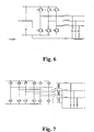
- Figs. 7 and 8 schematically illustrate two circuit topologies of the frequency converter 24.
- the circuit topology is selected so that the individual phase outputs of the frequency converter are controllable independent of the other phase outputs.
- the most common inverter topologies with star coupled or triangular coupled 3-phase transformers cannot be used, because of the absence of a physical neutral, In such couplings an asymmetric load will cause the three phases of the output voltage to become correspondingly asymmetric.
- a centre tap is provided from the DC voltage generated by the rectifier 40, and the switches generating the 400 Hz alternating output voltage are arranged for individual control of the output voltage of each of the output phases by proper pulse width modulation of the switches as is well known in the art.
- Fig. 7 In an alternative topology shown in Fig. 7 , twelve switches are arranged in three H-bridges connected to the DC voltage without a centre tap for provision of individually controllable output phase voltages. As shown in Fig. 7 , the H-bridge topology requires a transformer.
- controller is adapted for controlling the phase of the frequency converter output for synchronization with other power converters.
- the controller 46 is adapted to adjust the output voltage slightly as a function of the reactive load in such a way that the voltage decreases slightly and within allowable tolerances in response to an increase of the reactive load.
- the controller is adapted to adjust the output frequency slightly as a function of the active load in such a way that the frequency decreases slightly and within allowable tolerances in response to an increase of the active load. In case that two parallel-coupled units do not share a load equally, the unit supplying the least amount of power will have the highest output voltage and the highest output frequency, and therefore it will try to take over the load, until equal load sharing is obtained.
Landscapes
- Engineering & Computer Science (AREA)
- Architecture (AREA)
- Civil Engineering (AREA)
- Structural Engineering (AREA)
- Mechanical Engineering (AREA)
- Aviation & Aerospace Engineering (AREA)
- Power Engineering (AREA)
- Supply And Distribution Of Alternating Current (AREA)
- Inverter Devices (AREA)
- Ac-Ac Conversion (AREA)
- Laying Of Electric Cables Or Lines Outside (AREA)
- Emergency Protection Circuit Devices (AREA)
Priority Applications (9)
| Application Number | Priority Date | Filing Date | Title |
|---|---|---|---|
| DK05007033.3T DK1708348T3 (da) | 2005-03-31 | 2005-03-31 | Strømkonverter med justerbart udgangskabel |
| ES05007033T ES2347569T3 (es) | 2005-03-31 | 2005-03-31 | Convertidor de potencia con un cable de salida ajustable. |
| EP05007033A EP1708348B1 (en) | 2005-03-31 | 2005-03-31 | A power converter with an adjustable output cable |
| AT05007033T ATE472848T1 (de) | 2005-03-31 | 2005-03-31 | Stromwandler mit einstellbarem ausgangskabel |
| DE602005022048T DE602005022048D1 (de) | 2005-03-31 | 2005-03-31 | Stromwandler mit einstellbarem Ausgangskabel |
| CA2539050A CA2539050C (en) | 2005-03-31 | 2006-03-09 | A power converter with an adjustable output cable |
| CN2006100653376A CN1848576B (zh) | 2005-03-31 | 2006-03-17 | 带有可调节输出电缆的电源变换器 |
| US11/386,165 US7558085B2 (en) | 2005-03-31 | 2006-03-22 | Power converter with an adjustable output cable |
| JP2006094110A JP5085876B2 (ja) | 2005-03-31 | 2006-03-30 | 調整式出力ケーブルを備えた電力変換器 |
Applications Claiming Priority (1)
| Application Number | Priority Date | Filing Date | Title |
|---|---|---|---|
| EP05007033A EP1708348B1 (en) | 2005-03-31 | 2005-03-31 | A power converter with an adjustable output cable |
Publications (2)
| Publication Number | Publication Date |
|---|---|
| EP1708348A1 EP1708348A1 (en) | 2006-10-04 |
| EP1708348B1 true EP1708348B1 (en) | 2010-06-30 |
Family
ID=35520829
Family Applications (1)
| Application Number | Title | Priority Date | Filing Date |
|---|---|---|---|
| EP05007033A Active EP1708348B1 (en) | 2005-03-31 | 2005-03-31 | A power converter with an adjustable output cable |
Country Status (9)
| Country | Link |
|---|---|
| US (1) | US7558085B2 (it) |
| EP (1) | EP1708348B1 (it) |
| JP (1) | JP5085876B2 (it) |
| CN (1) | CN1848576B (it) |
| AT (1) | ATE472848T1 (it) |
| CA (1) | CA2539050C (it) |
| DE (1) | DE602005022048D1 (it) |
| DK (1) | DK1708348T3 (it) |
| ES (1) | ES2347569T3 (it) |
Families Citing this family (11)
| Publication number | Priority date | Publication date | Assignee | Title |
|---|---|---|---|---|
| US20100171373A1 (en) * | 2007-05-25 | 2010-07-08 | Illinois Tool Works, Inc. | Aircraft service pit with a ground power unit |
| NL2001644C2 (nl) | 2008-06-02 | 2009-12-03 | Nuon Tecno B V | Elektriciteitsdistributiesysteem, Transportmiddelverblijf, en Werkwijze. |
| US8120363B2 (en) * | 2008-11-24 | 2012-02-21 | Cummins Power Generation Ip, Inc. | Voltage drop compensation for an electric power storage device charging system |
| US8058745B2 (en) * | 2008-12-16 | 2011-11-15 | General Electric Company | Systems and methods providing a power converter |
| JP5678537B2 (ja) * | 2010-09-16 | 2015-03-04 | シンフォニアテクノロジー株式会社 | 航空機用静止型電源装置ユニット |
| JP2012223032A (ja) * | 2011-04-13 | 2012-11-12 | Yaskawa Electric Corp | 電力変換装置 |
| US10014790B2 (en) * | 2012-04-19 | 2018-07-03 | Illinois Tool Works Inc. | Dual function solid state converter |
| JP2014003763A (ja) * | 2012-06-15 | 2014-01-09 | Sinfonia Technology Co Ltd | 静止型空港電源 |
| DE102015207400A1 (de) * | 2014-05-12 | 2015-11-12 | Heidelberger Druckmaschinen Ag Intellectual Property | Kabelaufwickelvorrichtung mit Übertrager |
| RU2572822C1 (ru) * | 2014-09-24 | 2016-01-20 | Федеральное государственное бюджетное учреждение науки Институт проблем управления им. В.А. Трапезникова Российской академии наук | Способ удаленного проводного электропитания объектов |
| KR102427195B1 (ko) * | 2020-04-21 | 2022-08-02 | 현대자동차주식회사 | 차량이 도킹되는 오피스 시스템 및 그 제어방법 |
Family Cites Families (9)
| Publication number | Priority date | Publication date | Assignee | Title |
|---|---|---|---|---|
| DE3304276C1 (de) * | 1983-02-08 | 1984-08-02 | Schabmüller, Heinz, 8132 Tutzing | Verstauvorrichtung fuer das Anschlusskabel einer zentralen Bordnetzversorgungsanlage auf Flughaefen |
| DE9010213U1 (de) * | 1990-07-05 | 1990-10-18 | Manfred Fladung GmbH, 63776 Mömbris | Vorrichtung zum Verstauen eines dicken Kabels |
| GB9622585D0 (en) * | 1996-10-30 | 1997-01-08 | Ipr Investment Ltd | Battery charging unit |
| DE29704035U1 (de) | 1997-03-06 | 1997-05-22 | Manfred Fladung GmbH, 63776 Mömbris | Vorrichtung zur Aufnahme bzw. zum Verstauen eines Kabels |
| US6125048A (en) * | 1998-12-28 | 2000-09-26 | Lucent Technologies, Inc. | Method and apparatus for adjusting power delivered from a central power unit to a remote unit via a supply cable |
| JP2001004454A (ja) * | 1999-06-18 | 2001-01-12 | Yamari Sangyo Kk | 測温センサー繰り出し装置 |
| EP1278284B1 (en) * | 2001-07-16 | 2004-12-29 | Axa Power A/S | Cable voltage drop compensation in an electric power supply system |
| CN1219484C (zh) * | 2001-12-18 | 2005-09-21 | 乐金电子(天津)电器有限公司 | 电源线长度调整装置 |
| US6849962B2 (en) * | 2003-01-21 | 2005-02-01 | Honeywell International Inc. | Ground based aircraft electrical power generation system having a voltage regulator that selects from multiple points of regulation |
-
2005
- 2005-03-31 ES ES05007033T patent/ES2347569T3/es active Active
- 2005-03-31 AT AT05007033T patent/ATE472848T1/de active
- 2005-03-31 DE DE602005022048T patent/DE602005022048D1/de active Active
- 2005-03-31 EP EP05007033A patent/EP1708348B1/en active Active
- 2005-03-31 DK DK05007033.3T patent/DK1708348T3/da active
-
2006
- 2006-03-09 CA CA2539050A patent/CA2539050C/en active Active
- 2006-03-17 CN CN2006100653376A patent/CN1848576B/zh active Active
- 2006-03-22 US US11/386,165 patent/US7558085B2/en active Active
- 2006-03-30 JP JP2006094110A patent/JP5085876B2/ja active Active
Also Published As
| Publication number | Publication date |
|---|---|
| ES2347569T3 (es) | 2010-11-02 |
| DK1708348T3 (da) | 2010-10-04 |
| CN1848576B (zh) | 2010-07-21 |
| DE602005022048D1 (de) | 2010-08-12 |
| EP1708348A1 (en) | 2006-10-04 |
| ATE472848T1 (de) | 2010-07-15 |
| CA2539050A1 (en) | 2006-09-30 |
| CN1848576A (zh) | 2006-10-18 |
| CA2539050C (en) | 2010-10-05 |
| US7558085B2 (en) | 2009-07-07 |
| JP2006282165A (ja) | 2006-10-19 |
| JP5085876B2 (ja) | 2012-11-28 |
| US20060220468A1 (en) | 2006-10-05 |
Similar Documents
| Publication | Publication Date | Title |
|---|---|---|
| EP1708348B1 (en) | A power converter with an adjustable output cable | |
| KR101816803B1 (ko) | 드론의 전원공급시스템 | |
| US8733509B2 (en) | Multiple input voltage hoist system | |
| JP4718561B2 (ja) | エレベータシステム用作動装置 | |
| LU93105B1 (en) | A system for connecting an electrical power distribution of a ship to a shore side electrical power supply | |
| US20100171373A1 (en) | Aircraft service pit with a ground power unit | |
| EP2142459B1 (en) | Power supply appliance of a transport system | |
| CA2894780C (en) | Container based by-pass module for electric power lines | |
| CN108306516B (zh) | 一种自动收放电缆的飞机地面静变电源 | |
| JP2018538219A (ja) | ケーブル通過型ウインチ | |
| KR20140030857A (ko) | 무대장치의 와이어로프 탈선 시 모터 및 부하 보호 장치 | |
| CN218633740U (zh) | 电机控制系统及具有其的推进单元 | |
| FI115347B (fi) | Laite ja menetelmä sähköenergian varastoimiseksi reversiibelisti reversiibelin konversionsa avulla | |
| CN221447630U (zh) | 一种电缆盘及其电器模块 | |
| CN211826382U (zh) | 船用电动机综合检测装置 | |
| RU139486U1 (ru) | Устройство для электропитания авиационного средства при его контроле и обслуживании на земле | |
| RU2185296C1 (ru) | Устройство для электроснабжения и управления безрельсовым транспортным средством | |
| CA2825420C (en) | Hybrid electric shovel | |
| KR0125203Y1 (ko) | 차단기 인입출용 대차의 높이 조절장치 | |
| CN118300456A (zh) | 采煤机控制系统、采煤机电控系统及其上电方法 | |
| CN113175418A (zh) | 一种直驱发电机电动盘车装置 | |
| KR20110008577U (ko) | 전동기 테스트 장치 | |
| JP2019006532A (ja) | エレベーター及び電力供給制御方法 | |
| KR20080074701A (ko) | 인버터 테스트 장치 | |
| KR20130071971A (ko) | 해상 석유 생산 시설용 주파수 변환장치 |
Legal Events
| Date | Code | Title | Description |
|---|---|---|---|
| PUAI | Public reference made under article 153(3) epc to a published international application that has entered the european phase |
Free format text: ORIGINAL CODE: 0009012 |
|
| 17P | Request for examination filed |
Effective date: 20060323 |
|
| AK | Designated contracting states |
Kind code of ref document: A1 Designated state(s): AT BE BG CH CY CZ DE DK EE ES FI FR GB GR HU IE IS IT LI LT LU MC NL PL PT RO SE SI SK TR |
|
| AX | Request for extension of the european patent |
Extension state: AL BA HR LV MK YU |
|
| AKX | Designation fees paid |
Designated state(s): AT BE BG CH CY CZ DE DK EE ES FI FR GB GR HU IE IS IT LI LT LU MC NL PL PT RO SE SI SK TR |
|
| GRAP | Despatch of communication of intention to grant a patent |
Free format text: ORIGINAL CODE: EPIDOSNIGR1 |
|
| GRAS | Grant fee paid |
Free format text: ORIGINAL CODE: EPIDOSNIGR3 |
|
| GRAA | (expected) grant |
Free format text: ORIGINAL CODE: 0009210 |
|
| AK | Designated contracting states |
Kind code of ref document: B1 Designated state(s): AT BE BG CH CY CZ DE DK EE ES FI FR GB GR HU IE IS IT LI LT LU MC NL PL PT RO SE SI SK TR |
|
| REG | Reference to a national code |
Ref country code: CH Ref legal event code: EP Ref country code: GB Ref legal event code: FG4D |
|
| REG | Reference to a national code |
Ref country code: IE Ref legal event code: FG4D |
|
| REF | Corresponds to: |
Ref document number: 602005022048 Country of ref document: DE Date of ref document: 20100812 Kind code of ref document: P |
|
| REG | Reference to a national code |
Ref country code: DK Ref legal event code: T3 |
|
| REG | Reference to a national code |
Ref country code: NL Ref legal event code: VDEP Effective date: 20100630 |
|
| PG25 | Lapsed in a contracting state [announced via postgrant information from national office to epo] |
Ref country code: LT Free format text: LAPSE BECAUSE OF FAILURE TO SUBMIT A TRANSLATION OF THE DESCRIPTION OR TO PAY THE FEE WITHIN THE PRESCRIBED TIME-LIMIT Effective date: 20100630 Ref country code: SE Free format text: LAPSE BECAUSE OF FAILURE TO SUBMIT A TRANSLATION OF THE DESCRIPTION OR TO PAY THE FEE WITHIN THE PRESCRIBED TIME-LIMIT Effective date: 20100630 |
|
| REG | Reference to a national code |
Ref country code: ES Ref legal event code: FG2A Ref document number: 2347569 Country of ref document: ES Kind code of ref document: T3 |
|
| LTIE | Lt: invalidation of european patent or patent extension |
Effective date: 20100630 |
|
| PG25 | Lapsed in a contracting state [announced via postgrant information from national office to epo] |
Ref country code: FI Free format text: LAPSE BECAUSE OF FAILURE TO SUBMIT A TRANSLATION OF THE DESCRIPTION OR TO PAY THE FEE WITHIN THE PRESCRIBED TIME-LIMIT Effective date: 20100630 Ref country code: SI Free format text: LAPSE BECAUSE OF FAILURE TO SUBMIT A TRANSLATION OF THE DESCRIPTION OR TO PAY THE FEE WITHIN THE PRESCRIBED TIME-LIMIT Effective date: 20100630 |
|
| PG25 | Lapsed in a contracting state [announced via postgrant information from national office to epo] |
Ref country code: PL Free format text: LAPSE BECAUSE OF FAILURE TO SUBMIT A TRANSLATION OF THE DESCRIPTION OR TO PAY THE FEE WITHIN THE PRESCRIBED TIME-LIMIT Effective date: 20100630 Ref country code: GR Free format text: LAPSE BECAUSE OF FAILURE TO SUBMIT A TRANSLATION OF THE DESCRIPTION OR TO PAY THE FEE WITHIN THE PRESCRIBED TIME-LIMIT Effective date: 20101001 |
|
| PG25 | Lapsed in a contracting state [announced via postgrant information from national office to epo] |
Ref country code: EE Free format text: LAPSE BECAUSE OF FAILURE TO SUBMIT A TRANSLATION OF THE DESCRIPTION OR TO PAY THE FEE WITHIN THE PRESCRIBED TIME-LIMIT Effective date: 20100630 Ref country code: NL Free format text: LAPSE BECAUSE OF FAILURE TO SUBMIT A TRANSLATION OF THE DESCRIPTION OR TO PAY THE FEE WITHIN THE PRESCRIBED TIME-LIMIT Effective date: 20100630 |
|
| PG25 | Lapsed in a contracting state [announced via postgrant information from national office to epo] |
Ref country code: RO Free format text: LAPSE BECAUSE OF FAILURE TO SUBMIT A TRANSLATION OF THE DESCRIPTION OR TO PAY THE FEE WITHIN THE PRESCRIBED TIME-LIMIT Effective date: 20100630 Ref country code: PT Free format text: LAPSE BECAUSE OF FAILURE TO SUBMIT A TRANSLATION OF THE DESCRIPTION OR TO PAY THE FEE WITHIN THE PRESCRIBED TIME-LIMIT Effective date: 20101102 Ref country code: BE Free format text: LAPSE BECAUSE OF FAILURE TO SUBMIT A TRANSLATION OF THE DESCRIPTION OR TO PAY THE FEE WITHIN THE PRESCRIBED TIME-LIMIT Effective date: 20100630 Ref country code: SK Free format text: LAPSE BECAUSE OF FAILURE TO SUBMIT A TRANSLATION OF THE DESCRIPTION OR TO PAY THE FEE WITHIN THE PRESCRIBED TIME-LIMIT Effective date: 20100630 Ref country code: CY Free format text: LAPSE BECAUSE OF FAILURE TO SUBMIT A TRANSLATION OF THE DESCRIPTION OR TO PAY THE FEE WITHIN THE PRESCRIBED TIME-LIMIT Effective date: 20100630 Ref country code: CZ Free format text: LAPSE BECAUSE OF FAILURE TO SUBMIT A TRANSLATION OF THE DESCRIPTION OR TO PAY THE FEE WITHIN THE PRESCRIBED TIME-LIMIT Effective date: 20100630 Ref country code: IS Free format text: LAPSE BECAUSE OF FAILURE TO SUBMIT A TRANSLATION OF THE DESCRIPTION OR TO PAY THE FEE WITHIN THE PRESCRIBED TIME-LIMIT Effective date: 20101030 |
|
| PLBE | No opposition filed within time limit |
Free format text: ORIGINAL CODE: 0009261 |
|
| STAA | Information on the status of an ep patent application or granted ep patent |
Free format text: STATUS: NO OPPOSITION FILED WITHIN TIME LIMIT |
|
| 26N | No opposition filed |
Effective date: 20110331 |
|
| REG | Reference to a national code |
Ref country code: DE Ref legal event code: R097 Ref document number: 602005022048 Country of ref document: DE Effective date: 20110330 |
|
| PG25 | Lapsed in a contracting state [announced via postgrant information from national office to epo] |
Ref country code: MC Free format text: LAPSE BECAUSE OF NON-PAYMENT OF DUE FEES Effective date: 20110331 |
|
| REG | Reference to a national code |
Ref country code: CH Ref legal event code: PL |
|
| REG | Reference to a national code |
Ref country code: IE Ref legal event code: MM4A |
|
| PG25 | Lapsed in a contracting state [announced via postgrant information from national office to epo] |
Ref country code: IE Free format text: LAPSE BECAUSE OF NON-PAYMENT OF DUE FEES Effective date: 20110331 Ref country code: CH Free format text: LAPSE BECAUSE OF NON-PAYMENT OF DUE FEES Effective date: 20110331 Ref country code: LI Free format text: LAPSE BECAUSE OF NON-PAYMENT OF DUE FEES Effective date: 20110331 |
|
| PGFP | Annual fee paid to national office [announced via postgrant information from national office to epo] |
Ref country code: DK Payment date: 20130325 Year of fee payment: 9 |
|
| PG25 | Lapsed in a contracting state [announced via postgrant information from national office to epo] |
Ref country code: LU Free format text: LAPSE BECAUSE OF NON-PAYMENT OF DUE FEES Effective date: 20110331 |
|
| PG25 | Lapsed in a contracting state [announced via postgrant information from national office to epo] |
Ref country code: TR Free format text: LAPSE BECAUSE OF FAILURE TO SUBMIT A TRANSLATION OF THE DESCRIPTION OR TO PAY THE FEE WITHIN THE PRESCRIBED TIME-LIMIT Effective date: 20100630 Ref country code: BG Free format text: LAPSE BECAUSE OF FAILURE TO SUBMIT A TRANSLATION OF THE DESCRIPTION OR TO PAY THE FEE WITHIN THE PRESCRIBED TIME-LIMIT Effective date: 20100930 |
|
| PG25 | Lapsed in a contracting state [announced via postgrant information from national office to epo] |
Ref country code: HU Free format text: LAPSE BECAUSE OF FAILURE TO SUBMIT A TRANSLATION OF THE DESCRIPTION OR TO PAY THE FEE WITHIN THE PRESCRIBED TIME-LIMIT Effective date: 20100630 |
|
| REG | Reference to a national code |
Ref country code: DK Ref legal event code: EBP Effective date: 20140331 |
|
| PG25 | Lapsed in a contracting state [announced via postgrant information from national office to epo] |
Ref country code: DK Free format text: LAPSE BECAUSE OF NON-PAYMENT OF DUE FEES Effective date: 20140331 |
|
| REG | Reference to a national code |
Ref country code: FR Ref legal event code: PLFP Year of fee payment: 12 |
|
| REG | Reference to a national code |
Ref country code: FR Ref legal event code: PLFP Year of fee payment: 13 |
|
| REG | Reference to a national code |
Ref country code: FR Ref legal event code: PLFP Year of fee payment: 14 |
|
| P01 | Opt-out of the competence of the unified patent court (upc) registered |
Effective date: 20231101 |
|
| PGFP | Annual fee paid to national office [announced via postgrant information from national office to epo] |
Ref country code: AT Payment date: 20240304 Year of fee payment: 20 |
|
| PGFP | Annual fee paid to national office [announced via postgrant information from national office to epo] |
Ref country code: DE Payment date: 20240327 Year of fee payment: 20 Ref country code: GB Payment date: 20240327 Year of fee payment: 20 |
|
| PGFP | Annual fee paid to national office [announced via postgrant information from national office to epo] |
Ref country code: IT Payment date: 20240321 Year of fee payment: 20 Ref country code: FR Payment date: 20240325 Year of fee payment: 20 |
|
| PGFP | Annual fee paid to national office [announced via postgrant information from national office to epo] |
Ref country code: ES Payment date: 20240401 Year of fee payment: 20 |