EP1707812A1 - Hubkolbenmaschine - Google Patents
Hubkolbenmaschine Download PDFInfo
- Publication number
- EP1707812A1 EP1707812A1 EP05025616A EP05025616A EP1707812A1 EP 1707812 A1 EP1707812 A1 EP 1707812A1 EP 05025616 A EP05025616 A EP 05025616A EP 05025616 A EP05025616 A EP 05025616A EP 1707812 A1 EP1707812 A1 EP 1707812A1
- Authority
- EP
- European Patent Office
- Prior art keywords
- connecting rod
- crankshaft
- engine according
- drive shaft
- reciprocating piston
- Prior art date
- Legal status (The legal status is an assumption and is not a legal conclusion. Google has not performed a legal analysis and makes no representation as to the accuracy of the status listed.)
- Granted
Links
- 230000002093 peripheral effect Effects 0.000 claims description 2
- 238000007789 sealing Methods 0.000 claims 1
- 230000000694 effects Effects 0.000 abstract description 2
- 238000005452 bending Methods 0.000 description 5
- 230000002028 premature Effects 0.000 description 2
- 238000005299 abrasion Methods 0.000 description 1
- 230000001419 dependent effect Effects 0.000 description 1
- 238000011161 development Methods 0.000 description 1
- 230000018109 developmental process Effects 0.000 description 1
Images


Classifications
-
- F—MECHANICAL ENGINEERING; LIGHTING; HEATING; WEAPONS; BLASTING
- F04—POSITIVE - DISPLACEMENT MACHINES FOR LIQUIDS; PUMPS FOR LIQUIDS OR ELASTIC FLUIDS
- F04B—POSITIVE-DISPLACEMENT MACHINES FOR LIQUIDS; PUMPS
- F04B39/00—Component parts, details, or accessories, of pumps or pumping systems specially adapted for elastic fluids, not otherwise provided for in, or of interest apart from, groups F04B25/00 - F04B37/00
- F04B39/0094—Component parts, details, or accessories, of pumps or pumping systems specially adapted for elastic fluids, not otherwise provided for in, or of interest apart from, groups F04B25/00 - F04B37/00 crankshaft
Definitions
- the invention relates to a reciprocating piston engine, in particular piston compressor, according to the preamble of claim 1.
- the object of the present invention is to provide a reciprocating engine, in particular a reciprocating compressor of the type mentioned in such a way that even when using inexpensive cuff seals and inexpensive needle roller bearings premature failure is avoided by drive shaft bends and a long life is achieved.
- the invention proposes to arrange the connecting rod relative to the drive shaft in an angular or inclined position opposing a drive shaft deflection.
- This measure has shown that the wear of the boot seal and the needle bearing can be significantly reduced.
- the angular or oblique position produces a force vector at each pressure, which always pushes the connecting rod in the direction of the crankshaft with pin.
- This has the advantage that the connecting rod can be stored freely movable.
- the connecting rod is bent only slightly in the high pressure range.
- the radial forces on the cuff are reduced, which makes the material abrasion more uniform and reduces wear so that the cuff will last longer.
- the edge forces are reduced to the needle bearing, so that its life is increased.
- the low pressure range although the full angle or inclination is effective; However, since the outgoing of the drive shaft pressure forces are zero, the needle roller sleeve moves virtually without radial force.
- the angular position between connecting rod and drive shaft is realized by an oblique crankshaft bore for the drive shaft.
- the drive shaft bending can also be caused by a misalignment of the drive shaft, by a misalignment of the crankshaft journal bore in the crankshaft, by a misalignment of the cylindrical housing block bore for the piston or by a misalignment the bearing bore in the connecting rod for the crankshaft journal can be compensated.
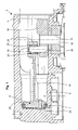
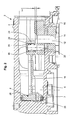
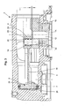
- FIG. 1-3 a compressor 2 with a housing block 4, with a cylinder 6 in the form of a housing block bore, with a cylinder 6 sealed by means of a sleeve seal 7 running piston 8, with a working on a crankshaft 10 drive motor (not shown), the drive shaft 12 is received by a bore 14 of the crankshaft 10, and with a connecting rod 16 for articulated connection of a crankshaft journal 18 of the crankshaft 10 with the piston 8 in a connecting rod needle bearing 20.
- the piston 8 is integral with the connecting rod sixteenth educated.
- Fig. 1 shows the piston 8 at top dead center
- Fig. 2 shows the piston 8 at top dead center at low pressure
- Fig. 3 shows the piston 8 at top dead center at high pressure.
- the connecting rod 16 shown in more detail in Figs. 4 and 5 has a connecting rod shaft 17, at one end of the molded disc-shaped piston 8 is arranged and at the other end a connecting rod bearing eye 24 is provided with bearing bore 25, the needle bearing 20 and therein Crankshaft pin 18 receives.
- the piston 8 has a peripheral step 26, to which the boot seal 7 is pressed by means of a clamping ring 28.
- FIGS. 6-9 show the crankshaft 10 with the bore 14 for the drive shaft 12 and with a bore 30 for receiving the crankshaft journal 18.
- the crankshaft 10 has a flange 34 divided by a slot 32 into two flange portions 34 ', 34 ".
- the flange portions 34 'and 34' ' are provided with mutually aligned bores 36, 38 for a clamping screw (not shown) for clamping the drive shaft 12th
- the bore 14 in the crankshaft 10 for the drive shaft 12 is formed to compensate for the drive shaft bending occurring during operation obliquely at an angle ⁇ (0.0 ° ⁇ ⁇ 1.5 °) relative to the vertical, which is shown schematically in FIG is, so that the drive shaft 12 relative to the connecting rod 16 has an angular position ⁇ and the connecting rod experiences a corresponding oblique position, which counteracts the drive shaft bending.
- the angular position between connecting rod and drive shaft is realized by an oblique crankshaft bore for the drive shaft.
- the drive shaft bending can also be compensated by a misalignment of the drive shaft, by a misalignment of the crankshaft journal bore in the crankshaft, by a misalignment of the cylindrical housing block bore for the piston or by a misalignment of the bearing bore in the connecting rod for the crankshaft journal.
- crank angle or connecting rod tilting angle of approximately 0.55 ° occurs due to the drive shaft bending, which causes the connecting rod to migrate by X. causes what is shown schematically in FIG. 2, this crank angle or Pleuelkippwinkel reduced by an angular position or inclination of the bore 14 for the drive shaft 12 by the angle ⁇ to about 0.1 ° and moves the connecting rod 16 only Y, which is shown schematically in Fig. 3, when ⁇ ⁇ 0.55 ° is selected, so that the radial forces on the boot seal 7 and the edge forces on the needle roller bearing 20 are negligibly small.
- the drive of the compressor can, for example, instead of the aforementioned direct drive by the electric motor by a belt drive, i. indirectly via the electric motor.
- the compressor is driven via a drive shaft connected to a pulley.
Landscapes
- Engineering & Computer Science (AREA)
- Mechanical Engineering (AREA)
- General Engineering & Computer Science (AREA)
- Compressor (AREA)
- Compressors, Vaccum Pumps And Other Relevant Systems (AREA)
- Shafts, Cranks, Connecting Bars, And Related Bearings (AREA)
- Pistons, Piston Rings, And Cylinders (AREA)
Abstract
Description
- Die Erfindung betrifft eine Hubkolbenmaschine, insbesondere Kolbenkompressor, gemäß Oberbegriff des Anspruchs 1.
- Bei den in Kraftfahrzeugen eingesetzten Kleinkompressoren treten im Betrieb vor allem im hohen Druckbereich relativ starke Durchbiegungen der Antriebswelle auf, durch die eine Kraft in Wellenlängsrichtung entsteht, die die Kolbendichtung und das Pleuellager stark belastet. Diese Belastung verursacht erhöhten Verschleiß der Kolbendichtung, was sich vor allem bei Verwendung preiswerter Manschettendichtungen bemerkbar macht, und des Pleuellagers, insbesondere bei Verwendung von preiswerten Nadellagern, deren Standzeit sich durch die durch die Durchbiegung der Antriebswelle verursachte Kantenpressung drastisch verringert. Der Verschleiß führt zu einem vorzeitigen Ausfall des Kompressors. Es wurden daher in der Vergangenheit teure, verschleißfestere und stabilere Bauteile, wie Kolbenringe als Kolbendichtung und Kugellager als Pleuellager verwendet.
- Die Aufgabe der vorliegenden Erfindung besteht darin, eine Hubkolbenmaschine, insbesondere einen Kolbenkompressor, der eingangs genannten Art so auszubilden, dass auch bei Verwendung preiswerter Manschettendichtungen und preiswerter Nadellager ein vorzeitiger Ausfall durch Antriebswellenbiegungen vermieden ist und eine lange Lebensdauer erreicht wird.
- Diese Aufgabe wird durch die Erfindung gemäß Anspruch 1 gelöst.
- Vorteilhafte und zweckmäßige Weiterbildungen der Aufgabenlösung sind in den Unteransprüchen angegeben.
- Die Erfindung schlägt vor, das Pleuel relativ zur Antriebswelle in einer einer Antriebswellendurchbiegung entgegenwirkenden Winkel- bzw. Schrägstellung anzuordnen. Diese Maßnahme hat gezeigt, dass der Verschleiß der Manschettendichtung und des Nadellagers erheblich reduziert werden kann. Durch die Winkel- bzw. Schrägstellung entsteht bei jedem Druck ein Kraftvektor, der das Pleuel immer in Richtung Kurbelwelle mit Zapfen drückt. Dies hat den Vorteil, dass das Pleuel frei beweglich gelagert werden kann. Das Pleuel wird im hohen Druckbereich nur noch geringfügig ausgeknickt. Die Radialkräfte auf die Manschette werden verringert, wodurch der Materialabrieb gleichmäßiger wird und der Verschleiß verringert wird, so dass die Manschette länger hält. Außerdem verringern sich die Kantenkräfte auf das Nadellager, so dass dessen Lebensdauer erhöht wird. Im niedrigen Druckbereich ist zwar die volle Winkel- bzw. Schrägstellung wirksam; da aber die von der Antriebswelle ausgehenden Druckkräfte bei null liegen, bewegt sich die Nadellager-Hülse praktisch ohne radiale Krafteinwirkung.
- Die Winkelstellung zwischen Pleuel und Antriebswelle wird durch eine schräge Kurbelwellenbohrung für die Antriebswelle realisiert. Die Antriebswellenbiegung kann auch durch eine Schiefstellung der Antriebswelle, durch eine Schiefstellung der Kurbelwellenzapfenbohrung in der Kurbelwelle, durch eine Schiefstellung der zylindrischen Gehäuseblock-Bohrung für den Kolben oder durch eine Schiefstellung der Lagerbohrung im Pleuel für den Kurbelwellenzapfen kompensiert werden.
- Die Erfindung soll nachfolgend anhand der beigefügten Zeichnung, in der ein Ausführungsbeispiel dargestellt ist, näher erläutert werden.
-
- Fig. 1
- eine 2D-Teildarstellung eines erfindungsgemäß ausgebildeten Kompressors mit einem Kolben im oberen Totpunkt,
- Fig. 2
- eine 2D-Teildarstellung des erfindungsgemäßen Kompressors mit dem Kolben im oberen Totpunkt im unteren Druckbereich,
- Fig. 3
- eine 2D-Teildarstellung des erfindungsgemäßen Kompressors mit dem Kolben im oberen Totpunkt im oberen Druckbereich,
- Fig. 4
- eine Ansicht eines beim erfindungsgemäßen Kompressor eingesetzten Pleuels,
- Fig. 5
- einen Schnitt A-A durch das Pleuel nach Fig. 4,
- Fig. 6
- eine Seitenansicht einer beim erfindungsgemäßen Kompressor verwendeten Kurbelwelle,
- Fig. 7
- einen Schnitt A-A durch die Kurbelwelle nach Fig. 6,
- Fig. 8
- eine Seitenansicht der Kurbelwelle mit eingesetztem Kurbelwellen-Zapfen und
- Fig. 9
- einen Schnitt A-A durch die Kurbelwelle nach Fig. 8
- Gleiche und einander entsprechende Bauteile in den Figuren der Zeichnung sind mit den gleichen Bezugszeichen versehen.
- Die Zeichnung zeigt in den Figuren 1-3 einen Kompressor 2 mit einem Gehäuseblock 4, mit einem Zylinder 6 in Form einer Gehäuseblockbohrung, mit einem im Zylinder 6 mittels einer Manschettendichtung 7 abgedichtet laufenden Kolben 8, mit einem auf eine Kurbelwelle 10 arbeitenden Antriebsmotor (nicht dargestellt), dessen Antriebswelle 12 von einer Bohrung 14 der Kurbelwelle 10 aufgenommen ist, und mit einem Pleuel 16 zur gelenkigen Verbindung eines Kurbelwellenzapfens 18 der Kurbelwelle 10 mit dem Kolben 8 in einem Pleuel-Nadellager 20. Der Kolben 8 ist einstückig mit dem Pleuel 16 ausgebildet.
- Die Fig. 1 zeigt den Kolben 8 im oberen Totpunkt, die Fig. 2 zeigt den Kolben 8 im oberen Totpunkt bei niedrigem Druck und die Fig. 3 zeigt den Kolben 8 im oberen Totpunkt bei hohem Druck.
- Das in den Fig. 4 und 5 näher dargestellte Pleuel 16 weist einen Pleuelschaft 17 auf, an dessen einem Ende der angeformte scheibenförmige Kolben 8 angeordnet ist und an dessen anderem Ende ein Pleuellagerauge 24 mit Lagerbohrung 25 vorgesehen ist, das das Nadellager 20 und darin den Kurbelwellenzapfen 18 aufnimmt.
- Der Kolben 8 weist eine periphere Stufe 26 auf, auf die die Manschettendichtung 7 mittels eines Spannrings 28 aufgepresst ist.
- Die Fig. 6-9 zeigen die Kurbelwelle 10 mit der Bohrung 14 für die Antriebswelle 12 und mit einer Bohrung 30 zur Aufnahme des Kurbelwellenzapfens 18.
- Die Kurbelwelle 10 weist einen durch einen Schlitz 32 in zwei Flanschteile 34', 34' ' geteilten Flansch 34 auf. Die Flanschteile 34' und 34' ' sind mit miteinander fluchtenden Bohrungen 36, 38 für eine Spannschraube (nicht dargestellt) versehen zum Einspannen der Antriebswelle 12.
- Die Bohrung 14 in der Kurbelwelle 10 für die Antriebswelle 12 ist zur Kompensation der im Betrieb auftretenden Antriebswellenbiegung schräg unter einem Winkel α (0,0° < α ≤ 1,5°) gegenüber der Senkrechten ausgebildet, was schematisch in der Fig. 7 eingezeichnet ist, so dass die Antriebswelle 12 gegenüber dem Pleuel 16 eine Winkelstellung α aufweist und das Pleuel eine entsprechende Schrägstellung erfährt, die der Antriebswellenbiegung entgegenwirkt.
- Die Winkelstellung zwischen Pleuel und Antriebswelle wird durch eine schräge Kurbelwellenbohrung für die Antriebswelle realisiert. Die Antriebswellenbiegung kann auch durch eine Schiefstellung der Antriebswelle, durch eine Schiefstellung der Kurbelwellenzapfenbohrung in der Kurbelwelle, durch eine Schiefstellung der zylindrischen Gehäuseblock-Bohrung für den Kolben oder durch eine Schiefstellung der Lagerbohrung im Pleuel für den Kurbelwellenzapfen kompensiert werden.
- Untersuchungen an einem Kraftfahrzeug-Kleinkompressor haben Folgendes ergeben: Wenn bspw. im Betrieb des Kompressors im hohen Druckbereich (bspw. 16 bar) durch die Antriebswellenbiegung ein Kurbelwinkel bzw. Pleuelkippwinkel von ca. 0,55° auftritt, der ein Auswandern des Pleuels um X bewirkt, was in der Fig. 2 schematisch dargestellt ist, verringert sich dieser Kurbelwinkel bzw. Pleuelkippwinkel durch eine Winkelstellung oder Schrägstellung der Bohrung 14 für die Antriebswelle 12 um den Winkel α auf ca. 0,1° und wandert das Pleuels 16 nur noch um Y aus, was in der Fig. 3 schematisch dargestellt ist, wenn α ≥ 0,55° gewählt wird, so dass die Radialkräfte auf die Manschettendichtung 7 und die Kantenkräfte auf das Nadellager 20 vernachlässigbar klein werden.
- Im unteren Druckbereich (gegen null bar) tritt praktisch keine Antriebswellenbiegung auf; es ist aber der Winkel α durch die Winkelstellung vorhanden. Dieser wirkt sich aber nicht negativ aus, da in diesem unteren Druckbereich die Druckkräfte praktisch null sind und somit keine zusätzliche Belastung der Manschettendichtung 7 und des Nadellagers 20 auftritt.
- Der Antrieb des Kompressors kann bspw. statt des vorgenannten Direktantriebs durch den Elektromotor auch durch einen Riementrieb, d.h. indirekt über den Elektromotor, erfolgen. Der Kompressor wird dabei über eine mit einer Riemenscheibe verbundene Antriebswelle angetrieben.
Claims (13)
- Hubkolbenmaschine, insbesondere Kolbenkompressor, mit einem Zylinder (6), mit einem im Zylinder (6) abgedichtet laufenden Kolben (8), mit einem auf eine Kurbelwelle (10) arbeitenden Antriebsmotor, dessen Antriebswelle (12) von einer Bohrung (14) der Kurbelwelle (10) aufgenommen ist, und mit einem Pleuel (16) zur gelenkigen Verbindung eines Kurbelwellenzapfens (18) der Kurbelwelle (10) mit dem Kolben (8) in einem Pleuellager (20), dadurch gekennzeichnet, dass das Pleuel (16) relativ zur Antriebswelle (12) in einer einer Antriebswellendurchbiegung entgegenwirkenden Winkel-/Schrägstellung (α) angeordnet ist.
- Hubkolbenmaschine nach Anspruch 1, dadurch gekennzeichnet, dass zur Erzielung der Winkel-/Schrägstellung (α) des Pleuels (16) die Kurbelwellenbohrung (14) für die Antriebswelle (12) schräg ausgebildet ist.
- Hubkolbenmaschine nach Anspruch 1, dadurch gekennzeichnet, dass die Winkel-/Schrägstellung des Pleuels (16) durch eine Schrägstellung der Antriebswelle realisiert ist.
- Hubkolbenmaschine nach Anspruch 1, dadurch gekennzeichnet, dass die Winkel-/Schrägstellung des Pleuels (16) durch eine Schrägstellung der zylindrischen Gehäuseblockbohrung (6) für den Kolben (8) realisiert ist.
- Hubkolbenmaschine nach Anspruch 1, dadurch gekennzeichnet, dass die Winkel-/Schrägstellung des Pleuels (16) durch eine Schrägstellung der Lagerbohrung (25) im Pleuellagerauge (24) für den Kurbelwellenzapfen (18) realisiert ist.
- Hubkolbenmaschine nach Anspruch 1, dadurch gekennzeichnet, dass die Winkel-/Schrägstellung des Pleuels (16) durch eine Schiefstellung der Kurbelwellenzapfenbohrung in der Kurbelwelle realisiert ist.
- Hubkolbenmaschine nach Anspruch 1, dadurch gekennzeichnet, dass für die Abdichtung des Kolbens (8) gegenüber der zylindrischen Gehäuseblockbohrung (6) eine Elastomerdichtung, insbesondere eine Manschettendichtung (7) oder eine Kolbenringdichtung vorgesehen ist.
- Hubkolbenmaschine nach Anspruch 1, dadurch gekennzeichnet, dass das Pleuellager (20) im Pleuellagerauge (24) für den Kurbelwellenzapfen (18) ein Nadellager, ein Gleitlager oder ein Kugellager ist.
- Hubkolbenmaschine nach Anspruch 1, dadurch gekennzeichnet, dass die Kurbelwelle (10) einen durch einen Schlitz (32) in zwei Flanschteile (34', 34") geteilten Flansch (34) aufweist, wobei die beiden Flanschteile (34', 34' ') mit miteinander fluchtenden Bohrungen (36, 38) für eine Spannschraube zum Einspannen der Antriebswelle (10) versehen sind.
- Hubkolbenmaschine nach einem der Ansprüche 1-5, dadurch gekennzeichnet, dass der Winkel (α) der Winkel/Schrägstellung zwischen 0° und 1,5° liegt.
- Hubkolbenmaschine nach Anspruch 7, dadurch gekennzeichnet, dass die Manschette der Manschettendichtung (7) durch einen Pressring (28) auf einer umlaufenden Stufe (26) des Kolbens (8) fixiert ist.
- Hubkolbenmaschine nach Anspruch 11, dadurch gekennzeichnet, dass der Kolben (8) einstückig mit dem Pleuel (16) ausgebildet ist.
- Hubkolbenmaschine nach Anspruch 1, dadurch gekennzeichnet, dass das Pleuellager (20) als Nadellager ausgebildet ist, wobei das Pleuellager (20) auf dem Kurbelwellenzapfen (18) axial beweglich ist.
Applications Claiming Priority (1)
| Application Number | Priority Date | Filing Date | Title |
|---|---|---|---|
| DE102005009947A DE102005009947A1 (de) | 2005-03-04 | 2005-03-04 | Hubkolbenmaschine |
Publications (2)
| Publication Number | Publication Date |
|---|---|
| EP1707812A1 true EP1707812A1 (de) | 2006-10-04 |
| EP1707812B1 EP1707812B1 (de) | 2010-01-20 |
Family
ID=36088570
Family Applications (1)
| Application Number | Title | Priority Date | Filing Date |
|---|---|---|---|
| EP05025616A Expired - Lifetime EP1707812B1 (de) | 2005-03-04 | 2005-11-24 | Hubkolbenmaschine |
Country Status (4)
| Country | Link |
|---|---|
| US (1) | US7305916B2 (de) |
| EP (1) | EP1707812B1 (de) |
| JP (1) | JP4978771B2 (de) |
| DE (2) | DE102005009947A1 (de) |
Cited By (3)
| Publication number | Priority date | Publication date | Assignee | Title |
|---|---|---|---|---|
| EP1801416A1 (de) * | 2005-12-22 | 2007-06-27 | WABCO GmbH | Hubkolbenmaschine |
| WO2018082800A1 (de) * | 2016-11-02 | 2018-05-11 | Wabco Europe Bvba | Hubkolbenmaschine, insbesondere ein-, zwei- oder mehrstufiger kolbenkompressor für eine druckluftversorgungsanlage eines fahrzeugs |
| WO2018082801A1 (de) * | 2016-11-02 | 2018-05-11 | Wabco Europe Bvba | Hubkolbenmaschine, druckluftversorgungsanlage, fahrzeug mit einer druckluftversorgungsanlage, verfahren zur montage und zum betrieb einer hubkolbenmaschine |
Families Citing this family (4)
| Publication number | Priority date | Publication date | Assignee | Title |
|---|---|---|---|---|
| DE102008031848B4 (de) | 2008-07-05 | 2018-09-13 | Wabco Gmbh | Kolbenkompressor |
| BRPI1103745A2 (pt) | 2011-08-30 | 2013-08-13 | Whirlpool Sa | biela de compressor alternativo |
| DE102011121750A1 (de) | 2011-12-21 | 2013-06-27 | Wabco Gmbh | Kompressor |
| WO2018139530A1 (ja) | 2017-01-26 | 2018-08-02 | 日立オートモティブシステムズ株式会社 | 往復動圧縮機 |
Citations (4)
| Publication number | Priority date | Publication date | Assignee | Title |
|---|---|---|---|---|
| US4848213A (en) * | 1988-01-11 | 1989-07-18 | The Devilbiss Company | Reciprocating piston compressor with offset cylinder |
| JP2002098044A (ja) * | 2000-09-22 | 2002-04-05 | Denso Corp | ポンプ |
| US20040042919A1 (en) * | 2002-08-31 | 2004-03-04 | Uwe Folchert | Reciprocating piston compressor for a gaseous medium |
| US20050008502A1 (en) * | 2001-08-31 | 2005-01-13 | Manke Adilson Luiz | Axial bearing arrangement for a hermetic compressor |
Family Cites Families (14)
| Publication number | Priority date | Publication date | Assignee | Title |
|---|---|---|---|---|
| US2054321A (en) * | 1935-04-26 | 1936-09-15 | Daniel W Hoferer | Crankpin construction |
| JPS53105620A (en) * | 1977-02-28 | 1978-09-13 | Honda Motor Co Ltd | Internal combustion engine |
| JPS59208180A (ja) * | 1983-05-11 | 1984-11-26 | Sanyo Electric Co Ltd | 密閉型電動圧縮機 |
| JPS60183283U (ja) * | 1984-05-17 | 1985-12-05 | 株式会社東芝 | 密閉形圧縮機 |
| US4924759A (en) * | 1988-08-01 | 1990-05-15 | Ingersoll-Rand Company | Press-fit retaining ring with extrusion-holding chamfer for wobble-piston cup seal |
| US5630340A (en) * | 1994-09-23 | 1997-05-20 | Yamaha Hatsudoki Kabushiki Kaisha | Connecting rod for engine |
| JP3193599B2 (ja) * | 1995-08-28 | 2001-07-30 | 株式会社日立製作所 | 往復動圧縮機 |
| US5644969A (en) * | 1996-06-28 | 1997-07-08 | Thomas Industries Inc. | Wobble piston and cylinder arrangement |
| JP2000283032A (ja) * | 1999-03-26 | 2000-10-10 | Sanyo Electric Co Ltd | 空気圧縮機 |
| US6357338B2 (en) * | 2000-07-19 | 2002-03-19 | Campbell Hausfeld/Scott Fetzer Company | Air compressor assembly with tapered flywheel shaft |
| US6896087B2 (en) * | 2000-09-01 | 2005-05-24 | Brp-Rotax Gmbh & Co. Kg | Component arrangement for an all terrain vehicle |
| KR100412575B1 (ko) * | 2002-01-23 | 2003-12-31 | 삼성광주전자 주식회사 | 밀폐형 왕복동식 압축기의 커넥팅로드 장치 |
| JP4423977B2 (ja) * | 2003-01-31 | 2010-03-03 | アイシン精機株式会社 | 車両用コンプレッサ装置 |
| JP2004293780A (ja) * | 2003-03-13 | 2004-10-21 | Ntn Corp | クランク機構における支持構造およびクランク機構の構成部品 |
-
2005
- 2005-03-04 DE DE102005009947A patent/DE102005009947A1/de not_active Withdrawn
- 2005-11-24 DE DE502005008907T patent/DE502005008907D1/de not_active Expired - Lifetime
- 2005-11-24 EP EP05025616A patent/EP1707812B1/de not_active Expired - Lifetime
-
2006
- 2006-01-25 US US11/339,982 patent/US7305916B2/en not_active Expired - Lifetime
- 2006-03-03 JP JP2006095666A patent/JP4978771B2/ja not_active Expired - Fee Related
Patent Citations (4)
| Publication number | Priority date | Publication date | Assignee | Title |
|---|---|---|---|---|
| US4848213A (en) * | 1988-01-11 | 1989-07-18 | The Devilbiss Company | Reciprocating piston compressor with offset cylinder |
| JP2002098044A (ja) * | 2000-09-22 | 2002-04-05 | Denso Corp | ポンプ |
| US20050008502A1 (en) * | 2001-08-31 | 2005-01-13 | Manke Adilson Luiz | Axial bearing arrangement for a hermetic compressor |
| US20040042919A1 (en) * | 2002-08-31 | 2004-03-04 | Uwe Folchert | Reciprocating piston compressor for a gaseous medium |
Non-Patent Citations (1)
| Title |
|---|
| PATENT ABSTRACTS OF JAPAN vol. 2002, no. 08 5 August 2002 (2002-08-05) * |
Cited By (4)
| Publication number | Priority date | Publication date | Assignee | Title |
|---|---|---|---|---|
| EP1801416A1 (de) * | 2005-12-22 | 2007-06-27 | WABCO GmbH | Hubkolbenmaschine |
| KR101330927B1 (ko) * | 2005-12-22 | 2013-11-18 | 바브코 게엠베하 | 왕복 피스톤 압축기 |
| WO2018082800A1 (de) * | 2016-11-02 | 2018-05-11 | Wabco Europe Bvba | Hubkolbenmaschine, insbesondere ein-, zwei- oder mehrstufiger kolbenkompressor für eine druckluftversorgungsanlage eines fahrzeugs |
| WO2018082801A1 (de) * | 2016-11-02 | 2018-05-11 | Wabco Europe Bvba | Hubkolbenmaschine, druckluftversorgungsanlage, fahrzeug mit einer druckluftversorgungsanlage, verfahren zur montage und zum betrieb einer hubkolbenmaschine |
Also Published As
| Publication number | Publication date |
|---|---|
| JP2006266268A (ja) | 2006-10-05 |
| US7305916B2 (en) | 2007-12-11 |
| JP4978771B2 (ja) | 2012-07-18 |
| EP1707812B1 (de) | 2010-01-20 |
| US20060196353A1 (en) | 2006-09-07 |
| DE502005008907D1 (de) | 2010-03-11 |
| DE102005009947A1 (de) | 2006-09-07 |
Similar Documents
| Publication | Publication Date | Title |
|---|---|---|
| EP2652326B1 (de) | Hochdruckpumpe | |
| DE10012904B4 (de) | Membraneinspannung mit Elastizitätsausgleich | |
| EP0250790A1 (de) | Kolbenmaschine | |
| EP1707812B1 (de) | Hubkolbenmaschine | |
| DE102008031848B4 (de) | Kolbenkompressor | |
| EP2561229A1 (de) | Kolben für eine radialkolbenmaschine | |
| DE102008060067B4 (de) | Axialkolbenmaschine mit einer Steuerplatte, die in einem Teilbereich des äußeren Dichtstegs eine erhöhte Elastizität aufweist | |
| EP1944510A1 (de) | Kolbenmaschine mit schwenkbar gelagerter Zylinderhülse | |
| DE102006026220B4 (de) | Fluidpumpe mit Kurbeltrieb | |
| EP1588051B1 (de) | Kolbenmaschine mit welle und wälzlager | |
| DE2801363C2 (de) | ||
| EP1801416B1 (de) | Hubkolbenmaschine | |
| DE2409572A1 (de) | Kreuzkopflager einer dieselbrennkraftmaschine | |
| DE102014220813B4 (de) | Stößelanordnung für eine Rollenstößelpumpe und eine solche aufweisende Rollenstößelpumpe | |
| EP0225477A2 (de) | Kolben für Brennkraftmaschinen | |
| DE10226492B4 (de) | Axialkolbenmaschine mit verstellbarem Kolbenhub | |
| DE102004026584A1 (de) | Kolbenpumpe mit verringertem Verschleiß | |
| DE102019202336A1 (de) | Exzenterantrieb einer Exzenterpumpe | |
| EP1831551B1 (de) | Trockenlaufender taumelscheibenverdichter mit einer beschichteten taumelscheibe | |
| DE2617879C3 (de) | Hydrostatische Axialkolbenmaschine | |
| DD253059A1 (de) | Hydrostatische axialkolbenmaschine | |
| DE102013210950A1 (de) | Optimierte Stößelbaugruppe | |
| DE2707949A1 (de) | Antrieb von hin- und hergehenden kolben von kolbenmaschinen, insbesondere kolbenpumpen | |
| EP1022461A2 (de) | Hochdruckpumpe | |
| DE102012211976B3 (de) | Hochdruckpumpe |
Legal Events
| Date | Code | Title | Description |
|---|---|---|---|
| PUAI | Public reference made under article 153(3) epc to a published international application that has entered the european phase |
Free format text: ORIGINAL CODE: 0009012 |
|
| AK | Designated contracting states |
Kind code of ref document: A1 Designated state(s): AT BE BG CH CY CZ DE DK EE ES FI FR GB GR HU IE IS IT LI LT LU LV MC NL PL PT RO SE SI SK TR |
|
| AX | Request for extension of the european patent |
Extension state: AL BA HR MK YU |
|
| RAP1 | Party data changed (applicant data changed or rights of an application transferred) |
Owner name: WABCO GMBH |
|
| 17P | Request for examination filed |
Effective date: 20070404 |
|
| AKX | Designation fees paid |
Designated state(s): DE FR GB IT |
|
| 17Q | First examination report despatched |
Effective date: 20070525 |
|
| GRAP | Despatch of communication of intention to grant a patent |
Free format text: ORIGINAL CODE: EPIDOSNIGR1 |
|
| GRAS | Grant fee paid |
Free format text: ORIGINAL CODE: EPIDOSNIGR3 |
|
| GRAA | (expected) grant |
Free format text: ORIGINAL CODE: 0009210 |
|
| AK | Designated contracting states |
Kind code of ref document: B1 Designated state(s): DE FR GB IT |
|
| REG | Reference to a national code |
Ref country code: GB Ref legal event code: FG4D Free format text: NOT ENGLISH |
|
| REF | Corresponds to: |
Ref document number: 502005008907 Country of ref document: DE Date of ref document: 20100311 Kind code of ref document: P |
|
| PLBE | No opposition filed within time limit |
Free format text: ORIGINAL CODE: 0009261 |
|
| STAA | Information on the status of an ep patent application or granted ep patent |
Free format text: STATUS: NO OPPOSITION FILED WITHIN TIME LIMIT |
|
| 26N | No opposition filed |
Effective date: 20101021 |
|
| REG | Reference to a national code |
Ref country code: FR Ref legal event code: TP Owner name: WABCO EUROPE BVBA, BE Effective date: 20130717 |
|
| REG | Reference to a national code |
Ref country code: GB Ref legal event code: 732E Free format text: REGISTERED BETWEEN 20131212 AND 20131218 |
|
| REG | Reference to a national code |
Ref country code: FR Ref legal event code: PLFP Year of fee payment: 11 |
|
| REG | Reference to a national code |
Ref country code: FR Ref legal event code: PLFP Year of fee payment: 12 |
|
| REG | Reference to a national code |
Ref country code: FR Ref legal event code: PLFP Year of fee payment: 13 |
|
| REG | Reference to a national code |
Ref country code: DE Ref legal event code: R081 Ref document number: 502005008907 Country of ref document: DE Owner name: WABCO EUROPE BVBA, BE Free format text: FORMER OWNER: WABCO GMBH, 30453 HANNOVER, DE |
|
| PGFP | Annual fee paid to national office [announced via postgrant information from national office to epo] |
Ref country code: DE Payment date: 20191130 Year of fee payment: 15 |
|
| PGFP | Annual fee paid to national office [announced via postgrant information from national office to epo] |
Ref country code: FR Payment date: 20191121 Year of fee payment: 15 Ref country code: IT Payment date: 20191120 Year of fee payment: 15 |
|
| PGFP | Annual fee paid to national office [announced via postgrant information from national office to epo] |
Ref country code: GB Payment date: 20191126 Year of fee payment: 15 |
|
| REG | Reference to a national code |
Ref country code: DE Ref legal event code: R119 Ref document number: 502005008907 Country of ref document: DE |
|
| GBPC | Gb: european patent ceased through non-payment of renewal fee |
Effective date: 20201124 |
|
| PG25 | Lapsed in a contracting state [announced via postgrant information from national office to epo] |
Ref country code: FR Free format text: LAPSE BECAUSE OF NON-PAYMENT OF DUE FEES Effective date: 20201130 Ref country code: IT Free format text: LAPSE BECAUSE OF NON-PAYMENT OF DUE FEES Effective date: 20201124 |
|
| PG25 | Lapsed in a contracting state [announced via postgrant information from national office to epo] |
Ref country code: DE Free format text: LAPSE BECAUSE OF NON-PAYMENT OF DUE FEES Effective date: 20210601 Ref country code: GB Free format text: LAPSE BECAUSE OF NON-PAYMENT OF DUE FEES Effective date: 20201124 |