EP1707101A2 - Geschirrkorb und dazugehöriger Halter - Google Patents
Geschirrkorb und dazugehöriger Halter Download PDFInfo
- Publication number
- EP1707101A2 EP1707101A2 EP06251253A EP06251253A EP1707101A2 EP 1707101 A2 EP1707101 A2 EP 1707101A2 EP 06251253 A EP06251253 A EP 06251253A EP 06251253 A EP06251253 A EP 06251253A EP 1707101 A2 EP1707101 A2 EP 1707101A2
- Authority
- EP
- European Patent Office
- Prior art keywords
- basket
- frame
- utensil rack
- utensil
- cabinet
- Prior art date
- Legal status (The legal status is an assumption and is not a legal conclusion. Google has not performed a legal analysis and makes no representation as to the accuracy of the status listed.)
- Granted
Links
Images


Classifications
-
- A—HUMAN NECESSITIES
- A47—FURNITURE; DOMESTIC ARTICLES OR APPLIANCES; COFFEE MILLS; SPICE MILLS; SUCTION CLEANERS IN GENERAL
- A47L—DOMESTIC WASHING OR CLEANING; SUCTION CLEANERS IN GENERAL
- A47L15/00—Washing or rinsing machines for crockery or tableware
- A47L15/42—Details
- A47L15/50—Racks ; Baskets
- A47L15/507—Arrangements for extracting racks, e.g. roller supports
-
- A—HUMAN NECESSITIES
- A47—FURNITURE; DOMESTIC ARTICLES OR APPLIANCES; COFFEE MILLS; SPICE MILLS; SUCTION CLEANERS IN GENERAL
- A47L—DOMESTIC WASHING OR CLEANING; SUCTION CLEANERS IN GENERAL
- A47L15/00—Washing or rinsing machines for crockery or tableware
- A47L15/42—Details
- A47L15/50—Racks ; Baskets
- A47L15/502—Cutlery baskets
-
- A—HUMAN NECESSITIES
- A47—FURNITURE; DOMESTIC ARTICLES OR APPLIANCES; COFFEE MILLS; SPICE MILLS; SUCTION CLEANERS IN GENERAL
- A47L—DOMESTIC WASHING OR CLEANING; SUCTION CLEANERS IN GENERAL
- A47L15/00—Washing or rinsing machines for crockery or tableware
- A47L15/42—Details
- A47L15/50—Racks ; Baskets
- A47L15/504—Arrangements for changing the height of racks
-
- A—HUMAN NECESSITIES
- A47—FURNITURE; DOMESTIC ARTICLES OR APPLIANCES; COFFEE MILLS; SPICE MILLS; SUCTION CLEANERS IN GENERAL
- A47L—DOMESTIC WASHING OR CLEANING; SUCTION CLEANERS IN GENERAL
- A47L15/00—Washing or rinsing machines for crockery or tableware
- A47L15/42—Details
- A47L15/50—Racks ; Baskets
- A47L15/505—Inserts, e.g. for holding baby bottles, stemware or cups
Definitions
- the invention relates generally to a utensil rack for use with a household dishwasher and a utensil basket supported by the utensil rack.
- the invention relates to a utensil rack adapted to hold a utensil basket in multiple vertical positions.
- the invention relates to a utensil rack having multiple basket elements that are complementary to form a whole basket.
- the invention relates to a utensil rack mounted to the dishwasher by a pair of slides having a closure member to prevent undesired removal of the utensil rack from the slides.
- a typical automatic dishwasher comprises a cabinet that defines a washing chamber, which is accessible through a moveable door.
- an upper and a lower rack for holding utensils to be cleaned are provided within the washing chamber.
- a silverware basket is also usually provided and normally mounts to the lower rack.
- the upper and lower racks are normally spaced so that larger utensils can be positioned in the lower rack and smaller utensils in the upper rack.
- Both the upper and lower racks are slidably mounted within the washing chamber in such a manner that at least a major portion of the racks can be slid substantially beyond the washing chamber to ease the loading of the racks.
- the types of utensils placed in an automatic dishwasher can vary greatly in size. Some utensils are very large, such as soup pots and roasting pans, other utensils are relatively small, such as silverware, serving spoons, and spatulas.
- the racks must also accommodate the traditional utensils of plates, glasses, saucer plates, mugs, etc. Since the utensil composition can vary greatly from load to load, contemporary automatic dishwashers must be configured or easily adaptable to accommodate these various size utensils to maximize the number of utensils washed during a given load. The maximization of the number of utensils in each load is a great convenience for the user and also reduces energy and water consumption.
- Some utensils are such that they can reduce the effective holding capacity of the automatic dishwasher, and thereby increase the need for multiple loads, resulting in an inefficient use of resources.
- An example of such a utensil is any utensil having a long and slender profile, such as a wooden spoon, a spatula, a ladle, etc. Often times, the length of these utensils makes it impossible for them to stand up within the silverware basket because the utensil will contact the other rack. To wash these types of utensils, it is necessary to lay them down in either the upper or lower racks where they often extend across a substantial portion of the rack floor.
- Smaller utensils with a slender profile can also take up more space than is warranted if they are placed on one of the racks. This is why they are commonly positioned upright in the silverware basket: Usually, the height of the silverware basket is about half the length or less of these smaller utensils. As a result, the smaller utensils tend to lean against the edges of the silverware basket and against one another, especially when the utensils are crowded in silverware basket, which can detrimentally affect the ability of the dishwasher to clean the utensils, especially at the interface of the utensils with the basket or other utensils.
- the racks include wheels or similar devices mounted to the sides thereof, and the wheels ride within a slide movably mounted to the cabinet.
- the user pulls the rack out of the wash chamber by sliding the wheel toward the end of the slide and, once the rack reaches the end of the slide, removes the wheels from the slide, usually by slightly lifting the rack to lift the wheel over a detent in the slide while continuing to pull.
- Fig. 1 shows a household dishwasher 10 according to one embodiment of the invention comprising a cabinet 12 having spaced upper and lower walls 14, 16 joined by opposing side walls 18, 20 and a rear wall 22 to form an open-faced wash chamber 24.
- a door 26 movably mounted to the cabinet 12 is movable between an open position, as shown in Fig. 1, wherein the user can access the wash chamber 24, and a closed position, wherein the door 26 closes the open face of the wash chamber 24 in a conventional fashion.
- the dishwasher 10 further comprises a lower, first utensil rack 28 and a higher, second utensil rack 30 slidably mounted the side walls 18, 20 of the cabinet 12.
- the first and second utensil racks 28, 30 are preferably conventional utensil racks commonly utilized in present day household dishwashers for holding various utensils, such as plates, bowls, other tableware, and beverage containers.
- the first utensil rack 28 is adapted to hold plates, bowls, and large items, such as pots and pans, and the second utensil rack 30 is spaced a sufficient distance above the first utensil rack 28 to accommodate the items in the first utensil rack 30.
- the second utensil rack 30 commonly holds beverage containers, such as glasses and cups, and other small items.
- the first and second utensil racks 28, 30 can be arranged in the dishwasher 10 in any suitable fashion and can hold any utensils that can be washed in the dishwasher 10.
- the door 26 is in the closed position, and the first and second utensil racks 28, 30 are disposed within the wash chamber 24 and exposed to washing fluid, such as water, and wash aids, such as detergents and rinse aids.
- wash aids such as detergents and rinse aids.
- the dishwasher 10 can further comprise a third utensil rack 40 slidably mounted to the cabinet 12 by a pair of slides 42.
- the third utensil rack 40 can be positioned above the second utensil rack 30 and near the upper wall 14 within the wash chamber 24 and can move relative to the wash chamber 24 in the same manner as described above for the first and second utensil racks 28, 30.
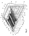
- the third utensil rack 40 comprises a frame 44 that supports a pair of removable basket elements 46A, 46B, which can hold several types of utensils having various sizes and shapes.
- the frame 44 comprises an upper U-shaped wire 48 and a generally rectangular lower peripheral wire 50 joined by a plurality of spaced and generally vertical connecting wires 52.
- the peripheral wires 48, 50 form spaced front and rear ends 54, 56 connected by opposing sides 58, 60.
- the U-shaped wire 48 is oriented such that it opens at the rear end 56, and the lower peripheral wire 50 is formed by a pair of opposed, U-shaped front and rear lower peripheral wires 50A, 50B that join at the opposing sides 58, 60.
- the frame 44 further comprises a front upper support rail 62 and a rear upper support rail 63 that extend between and above the opposing sides 58, 60 of the upper peripheral wire 48 and are parallel to and spaced from the front end 54 and the rear end 56, respectively. Additionally, the frame 44 includes a first pair of opposing lower support rails 64 and a second pair of opposing lower support rails 66 on the opposing sides 58, 60 of the frame 44.
- the first pair of lower support rails 64 is integral with the front upper support rail 62, and, similarly, the second pair of lower support rails 66 is integral with the rear upper support rail 63.
- Each of the lower support rails 64, 66 is elongated and generally U-shaped and depends from the upper peripheral wire 48 such that it extends below the lower peripheral wire 50.
- the upper support rails 62, 63 are vertically spaced from the lower support rails 64, 66.
- the upper and lower peripheral wires 48, 50, the upper support rails 62, 63, and the lower support rails 64, 66 are preferably metal wires coated with polymeric materials that can withstand the environment of the wash chamber 24 and protect the metal wires from corrosion.
- the upper and lower peripheral wires 48, 50, the upper support rails 62, 63, and the lower support rails 64, 66 can be composed entirely of polymeric materials.
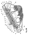
- the basket elements 46A, 46B which rest on the frame 44, each comprise an upstanding peripheral wall 70 and a grid formed by a plurality of intersecting ribs 72 that form a bottom wall surrounded by the peripheral wall 70.
- the intersecting ribs 72 are spaced from one another a distance suitable for holding utensils such as silverware, spatulas, and the like.
- the bottom wall optionally includes at least one small item support area 68 comprising intersecting support ribs 86 that are spaced closer than the intersecting ribs 72 to support small items, such as com cob holders, that can potentially fall between the intersecting ribs 72.
- the small item support areas 68 are preferably located in corners of basket elements 46A, 46B, but they can be located in any suitable region of the bottom wall.
- the peripheral wall 70 comprises parallel and spaced first and second edges 70A, 70B joined by spaced third and fourth edges 70C, 70D.
- Each of the first and second edges 70A, 70B are substantially straight and can include a carry handle 80 formed integrally therewith.
- Each of the handles can comprise a lateral hook or flange 82 sized to receive the upper and lower support rails 62, 63, 64, 66.
- the third edge 70C is generally straight and perpendicular to the first and second edges 70A, 70B, while the fourth edge 70D can comprise an intermediate curve 74 to form a first basket element portion 76 and a second basket element portion 78 that is wider than the first basket element portion 76.
- utensils of different length can be efficiently arranged within the basket elements 46A, 46B.
- relatively short utensils A such as standard forks and spoons
- medium length utensils B such as table knives
- the basket elements 46A, 46B are sized so that relatively long utensils C, such as spatulas, mixing spoons, chef knives, and the like, can be arranged across both the first and second basket element portions 76, 78 in an orientation parallel to the third edge 70C and generally perpendicular to the relatively short utensils A and the medium length utensils B. As illustrated in Fig. 4, the relatively long utensils C are longer than the medium length utensils B, which are longer than the relatively short utensils A.
- the utensils can be placed in any suitable location of the basket elements 46A, 46B.
- the relatively short utensils A can be placed in the second basket element portion 78, if desired.
- Each basket element 46A, 46B can further comprise a plurality of tines 88 projecting upward from the intersecting ribs 72 to support and separate individual utensils.
- the tines 88 can be arranged in groups so that the user can efficiently position utensils of different length in different areas of the basket elements 46A, 46B.
- a first tine group 90 extends along the fourth edge 70D for holding utensils in an orientation parallel to the first and second edges 70A, 70B, and a second tine group 92 is disposed along the second edge 70B for holding utensils in an orientation parallel to the third edge 70C.
- the tines 88 in the first tine group 90 are spaced to hold relatively thin utensils, such as table knives, spoons, and forks (i.e., the relatively short utensils A and the medium length utensils B), while the tines 88 in the second tine group 92 are spaced farther apart to accommodate wider utensils, such as spatulas (i.e., the relatively long utensils C).
- the tines 88 are preferably arranged in pairs of tines to form two parallel rows 88A, 88B of tines 88.
- the utensils positioned between the tines 88 are held by the tines 88 at two locations along the length thereof, and, therefore, the rows 88A, 88B of tines 88 prevent pivotal movement of the utensils and maintain the utensils in the orientation generally parallel to the first and second edges 70A, 70B or parallel to the third edge 70C.
- the second group of tines 92 includes a third row 88C of tines 88 along the first edge 70A for securing both ends of the relatively long utensils C to prevent the pivotal movement thereof.
- the fourth edges 70D of the basket elements 46A, 46B are complementary and matingly abut one another when the basket elements 46A, 46B are seated on the frame 44.
- the first edges 70A, the second edges 70B, and the third edges 70C of both of the basket elements 46A, 46B form a generally rectangular periphery with a minor discontinuation at the interface between the basket elements 46A, 46B.
- the basket elements 46A, 46B are complementary, the basket elements 46A, 46B mate to form a whole, generally rectangular basket.
- the whole basket is defined by the rectangular periphery and has a surface area slightly less than the area defined between the front and rear ends 54, 56 and the opposing sides 58, 60 of the frame 44.
- the whole basket corresponds to a single basket sized to span in one direction between the upper support rails 62, 63 and in the other direction a distance slightly less than the distance between the first and second pairs of opposing lower support rails 64, 66.
- the first basket element portion 76 of the first basket element 46A aligns with the second basket element portion 78 of the second basket element 46B
- the second basket element portion 78 of the first basket element 46A aligns with the first basket element portion 76 of the second basket element 46B to form the whole basket, which has a constant width equal to the sum of the individual widths of the basket element portions 76, 78.
- the basket elements 46A, 46B are identical in shape and size so that each of the basket elements 46A, 46B accounts for about one half of the whole basket. Further, production costs are minimized when the basket elements 46A, 46B are identical because only a single mold design is required for all of the basket elements 46A, 46B.
- the basket elements 46A, 46B are adjustably mounted to the frame 44 to accommodate utensils held by the second utensil rack 30 and utensils held by the basket elements 46A, 46B and to efficiently utilize the limited space in the wash chamber 24.
- the basket elements 46A, 46B can be vertically adjustable on the frame 44 and, therefore, within the wash chamber 24.
- the basket elements 46A, 46B can be mounted in an upper position wherein the flanges 82 on the first and second edges 70A, 70B rest on the upper support rails 62, 63. As shown in Figs.
- the basket elements 46A, 46B can be mounted in a lower position, wherein the flanges 82 on the first and second edges 70A, 70B rest on the first and second pairs of opposing lower support rails 64, 66.
- a comparison of Figs. 5 and 7 shows that the basket elements 46A, 46B are located higher in the wash chamber 24 when in the upper position.
- the bottom walls formed by the intersecting ribs 72 of the basket elements 46A, 46B are spaced from the second utensil rack 30 a greater distance when the basket elements 46A, 46B are in the upper position than when the basket elements 46A, 46B are in the lower position, but clearance between the bottom walls and the upper wall 14 of the cabinet 12 is greater when the basket elements 46A, 46B are in the lower position than when in the upper position. Mounting the basket elements 46A, 46B in the upper and the lower positions is, therefore, a compromise between spacing between the second utensil rack 30 and the third utensil rack 40 and clearance between the third utensil rack 40 and the upper wall 14 of the cabinet 12.
- the basket elements 46A, 46B in the upper position are oriented generally orthogonal to the basket elements 46A, 46B in the lower position because the portions of the frame 44 that support the basket elements 46A, 46B in these two positions are oriented orthogonal to one another.
- Such an arrangement facilitates mounting the basket elements 46A, 46B to the frame 44 since the upper support rails 62, 63 do not interfere with the basket elements 46A, 46B when mounting them on the first and second pairs of opposing lower support rails 64, 66 and vice-versa.
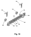
- the slides 42 that slidably mount the third utensil rack 40 to the cabinet 12 each comprise a track 100 having a generally vertical middle wall 102 with an aperture 103 near a front end thereof and pairs of upper and lower L-shaped flanges 104, 106 extending along the middle wall 102 to define an inner raceway 110 on an interior side (i.e., the side closer to the third utensil rack 40) of the middle wall 102 and an outer raceway 110 on an outer side (i.e., the side farther from the third utensil rack 40) of the middle wall 102.
- the raceways 110, 112 terminate at a pair of stops in the form of front flanges 108 at the front end of the track 100.
- the upper flange 104 that partially defines the inner raceway 110 is spaced from the front flange 108 on the interior side of the middle wall 102 to form an access opening 114 therebetween.
- a closure 120 pivotally mounted to the upper and lower flanges 104, 106 of the track 100 selectively blocks the access opening 114.
- the closure 120 comprises parallel upper and lower walls 122, 124 joined by a side wall 126 and a front wall 128 orthogonal to the side wall 126.
- the side wall 126 and the front wall 128 form a grip 130 sized to be grasped between a user's fingers for pivotally moving the closure 120.
- the closure 120 includes a detent 132 that extends from the side wall 126 and is sized to mate with the aperture 103.
- the closure 120 is movable between a closed position, as shown in Fig. 9A, wherein the upper wall 122 blocks the access opening 114, and an opened position, as illustrated in Fig. 9B, wherein the closure 120 is pivoted away from the track 100 so that the upper wall 122 is spaced from the access opening 114.
- a wheel support 140 couples each opposing side 58, 60 of the third utensil rack 40 to its corresponding slide 42.
- Each wheel support 140 is an elongated, generally rectangular member with front and rear wheels 142, 144 rotatably mounted to an outer side thereof.
- the wheels 142, 144 are sized for receipt within the access opening 114 and the inner raceway 110.
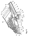
- the wheel support 140 further includes a pair of parallel grooves 146 on an interior side thereof for receiving the upper and lower peripheral wires 48, 50 of the frame 44. Snap clamps 150 adjacent the grooves 146 are sized to securely receive at least one of the upper and lower peripheral wires 48, 50 to prevent lateral translation of the wheel support 140 relative to the frame 44.
- the interior side of the wheel support 140 includes sets of vertically aligned U-shaped projections 148 between the grooves 146 sized to receive brackets 152 for sandwiching the frame 44 between the wheel support 140 and the brackets 152 to thereby mount the wheel support 140 to the frame 44.
- the wheel support 140 also comprises an upwardly and outwardly extending overhang 154 to facilitate mounting the wheel support 140 to the track 100.
- Each of the slides 42 is mounted to the dishwasher 10 by attaching the track 100 to a conventional slide mount (not shown) on the corresponding opposing side wall 18, 20.
- the track 100 receives the slide mount within the outer raceway 112 so that the track 100 can slide relative to the cabinet 12.
- the wheel supports 140 are mounted to the opposing sides 58, 60 of the frame 44 by aligning the upper and lower peripheral wires 48, 50 with the grooves 146, snapping the lower peripheral wire 50 into the snap clamps 150, and inserting the brackets 152 into the projections 148 to clamp the upper and lower peripheral wires 48, 50 between the wheel support 140 and the brackets 150.
- the user pivots the closures 120 on the slides 42 to the opened position so that the rear wheels 144 can be inserted into the inner raceways 110 through the access openings 114.
- the user then pushes the frame 44 towards the wash chamber 24 so that the rear wheels 144 travel along the inner raceway 110 until the front wheels 142 are aligned with the access openings 114, as shown in Fig. 11.
- the user pivots the closures 120 toward the track 100 to the closed position, wherein the detents 132 mate with the apertures 103, and the upper walls 122 block the access openings 114 to prevent inadvertent removal of the front wheels 142 from the inner raceways 110, as shown in Fig. 9A.
- the overhangs 154 of the wheel supports 140 rest on the upper flanges 104 of the track 100 to help support the frame 44 on the slides 42.
- the user can mount the basket elements 46A, 46B to the frame 44 in either the upper position or the lower position depending on the desired configuration of the utensil racks 28, 30, 40 in the wash chamber 24, the sizes of the utensils in the second utensil rack 30, and the sizes of the utensils to be held in the third utensil rack 40.
- the basket elements 46A, 46B are placed adjacent one another in the upper position, as shown in Figs. 2 and 5, with the flanges 82 on the upper support rails 62, 63.
- the basket elements 46A, 46B are positioned with their complementary, fourth edges 70D in abutting contact to form the whole basket.
- the basket elements 46A, 46B are rotated 90-degrees and placed adjacent one another in the lower position, as illustrated in Figs. 6 and 7, with the flanges 82 on the first and second opposing pairs of lower support rails 64, 66.
- the basket elements 46A, 46B are positioned with their complementary, fourth edges 70D in abutting contact to form the whole basket.
- the user can fill the basket elements 46A, 46B with various shapes and sizes of utensils, including the relatively short utensils A, the medium length utensils B, and the relatively long utensils C, as described above.
- the utensils can be arranged in the basket elements 46A, 46B in any suitable fashion to maximize the quantity of utensils held by the third utensil rack 40 without compromising the ability of the dishwasher 10 to clean the utensils.
- the user can place small items, such as corn cob holders, in the small item support areas 68. During operation of a wash cycle, the tines 88 surrounding the small item support areas 68 help retain the small items in the small item support areas 68.
- the user pulls the third utensil rack 40 from the wash chamber to empty the basket elements 46A, 46B.
- the front stop flanges 108 limit the forward movement of the frame 44 relative to the slides 42.
- the user removes the utensils from the third utensil rack 40 in any suitable manner.
- the user can either manually remove each utensil from the basket elements 46A, 46B while the basket elements 46A, 46B are mounted to the frame 44, the user can remove at least one of the basket elements 46A, 46B with the utensils therein and empty the at least one basket element 46A, 46B at a location separate from the dishwasher 10, or the user can remove at least one of the basket elements 46A, 46B with the utensils therein and use the at least one basket element 46A, 46B for utensil storage, such as by placing the at least one basket element 46A, 46B in a drawer.
- the user pivots the closures 120 away from the tracks 100 to the opened position, as shown in Fig. 9B, to unblock the access openings 114.
- the user aligns the front wheels 142 with the access openings 114 and lifts the frame 44 to thereby lift the front wheels 142 through the access openings 114, as illustrated in Fig. 11.
- the user pulls the frame 44 further from the wash chamber 24 until the rear wheels 144 are aligned with the access openings 114 and lifts the frame 44 to thereby lift the rear wheels 144 through the access openings 114 and disconnect the frame 44 from the slides 42.
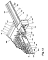
- FIG. 12 An alternative slide 42' is illustrated in Fig. 12, where components similar to those of the first embodiment slide 42 are identified with the same numeral bearing a prime (') symbol.
- the slide 42' is substantially identical to the first embodiment slide 42, except that the track 100' does not include the front flange stops 108, and the upper and the lower flanges 104', 106' extend all the way to the end of the track 100'.
- the access opening 114' is defined between the ends of the upper and lower flanges 104', 106', and the closure 120' in the closed position functions as the stop while blocking the access opening 114'.
- the access opening 114 can be located elsewhere in the track 100.
- the access opening 114 can be formed between the lower flange 106 and the front flange stop 108 if the lower flange 106 is sufficiently spaced from the front end of the track 100.
- the complementary basket elements 46A, 46B have been described with respect to the number, shape, and size shown in the figures. However, it is within the scope of the invention for the whole basket to be formed by more than two basket elements and for the basket elements to be shaped and sized in any suitable manner as long as they are complementary and together form the whole basket.
- the whole basket can be formed by two or more rectangular basket elements having straight edges, a first L-shaped basket element and a second square or rectangular basket element, two triangular basket elements, or basket elements similar to the basket elements 46A, 46B but having a fourth edge 70D with a different contour.
- the basket elements 46A, 46B are not limited to use with the frame 44; the basket elements 46A, 46B can be utilized with any suitable frame or utensil rack and are not required to be vertically adjustable within the wash chamber 24.
- the frame 44 can mount a unitary whole basket rather than separate basket elements so that the unitary whole basket is vertically adjustable within the wash chamber 24.
- the third utensil rack 40 has been shown and described as being located near the upper wall 14 of the cabinet 12 and in conjunction with the first and the second utensil racks 28, 30, it is within the scope of the invention to utilize the third utensil rack 40 in any location within the wash chamber 24, such as adjacent the lower wall 16 or in the middle of the wash chamber 24, and with or without other utensil racks.
- the slides 42 are not limited for use with the third utensil rack 40; rather, the slides 42 can be used with the first utensil rack 28, the second utensil rack 30, or any other suitable utensil rack.
- the grid of the basket elements 46A. 46B has been described as being formed by the plurality of intersecting ribs 72; however, it is within the scope of the invention for the grid to be formed by other structures having apertures or gaps that allow wash liquid to pass through the bottom wall of the basket elements 46A, 46B.
- the grid can be a molded panel with circular, rectangular, or other shaped apertures formed therein.
- the dishwasher 10 can be any type of appliance for washing dishes and is not limited to the dishwasher 10 shown in the figures.
- the dishwasher can be a drawer-type dishwasher, wherein the wash chamber is formed in an open-top drawer that is slidably mounted to a cabinet.
- the slides 42 can be used to slidably mount the drawer to the cabinet, if desired.
- the third utensil rack 40 accommodates various shapes and sizes of utensils for effective cleaning thereof without dramatically sacrificing capacity of the first and second utensil racks 28, 30. Because the basket elements 46A, 46B are vertically adjustable, the third utensil rack 40 can be arranged to accommodate the sizes of utensils in the second utensil rack 30.
- various portions of the frame 44 such as the upper support rails 62, 63 and the lower support rails 64, 66, function as height adjusters for adjustably mounting the basket elements 46A, 46B to the frame 44.
- the height adjusters can also be located on the basket elements 46A, 46B.
- the basket elements 46A, 46B can include multiple hooks vertically spaced on the peripheral wall 70 such that the basket elements 46A, 46B can be mounted to a portion of the frame 44 in different vertical orientations depending on which hooks mate with the portion of the frame 44.
Applications Claiming Priority (1)
| Application Number | Priority Date | Filing Date | Title |
|---|---|---|---|
| US11/092,453 US7455066B2 (en) | 2005-03-29 | 2005-03-29 | Dishwasher utensil rack and utensil basket therefor |
Publications (3)
| Publication Number | Publication Date |
|---|---|
| EP1707101A2 true EP1707101A2 (de) | 2006-10-04 |
| EP1707101A3 EP1707101A3 (de) | 2007-01-03 |
| EP1707101B1 EP1707101B1 (de) | 2014-06-04 |
Family
ID=36609272
Family Applications (1)
| Application Number | Title | Priority Date | Filing Date |
|---|---|---|---|
| EP06251253.8A Not-in-force EP1707101B1 (de) | 2005-03-29 | 2006-03-09 | Besteckkorb und automatischer Geschirrspüler umfassend den Besteckkorb |
Country Status (4)
| Country | Link |
|---|---|
| US (1) | US7455066B2 (de) |
| EP (1) | EP1707101B1 (de) |
| CA (1) | CA2538747C (de) |
| MX (1) | MXPA06003538A (de) |
Cited By (10)
| Publication number | Priority date | Publication date | Assignee | Title |
|---|---|---|---|---|
| EP1854395A1 (de) * | 2006-05-09 | 2007-11-14 | Whirlpool Corporation | Geschirrspüler mit Besteckkorb und Führungen dafür |
| WO2009041899A1 (en) * | 2007-09-24 | 2009-04-02 | Asko Cylinda Ab | Dish basket system for dishwashers |
| WO2010012572A1 (en) * | 2008-07-31 | 2010-02-04 | Arcelik Anonim Sirketi | A dishwasher |
| EP2371260A1 (de) * | 2010-03-30 | 2011-10-05 | FagorBrandt SAS | Hilfsvorrichtung zur Positionsbeibehaltung eines Korbs in einem Behälter einer Geschirrspülmaschine |
| WO2013098027A1 (en) * | 2011-12-27 | 2013-07-04 | Arcelik Anonim Sirketi | A dishwasher comprising a carrier |
| WO2013098029A1 (en) * | 2011-12-27 | 2013-07-04 | Arcelik Anonim Sirketi | A dishwasher comprising a carrier |
| CN107185925A (zh) * | 2016-03-15 | 2017-09-22 | 万国洗濯科技有限公司 | 适于瓶体或类似容器的容纳篮 |
| CN108042077A (zh) * | 2018-01-11 | 2018-05-18 | 苏州科洁泰电器有限公司 | 洗碗机喷淋装置 |
| EP3766402A1 (de) * | 2019-07-03 | 2021-01-20 | LG Electronics Inc. | Gestell für geschirrspülmaschine und geschirrspülmaschine damit |
| EP4245204A1 (de) * | 2022-03-15 | 2023-09-20 | Whirlpool Corporation | Geschirrspülmaschine mit tablett |
Families Citing this family (40)
| Publication number | Priority date | Publication date | Assignee | Title |
|---|---|---|---|---|
| KR101310264B1 (ko) * | 2006-09-21 | 2013-09-23 | 엘지전자 주식회사 | 식기세척기의 랙 |
| DE102006055350A1 (de) | 2006-11-23 | 2008-05-29 | BSH Bosch und Siemens Hausgeräte GmbH | Besteckkorb für eine Geschirrspülmaschine und Geschirrspülmaschine |
| DE102006055352A1 (de) * | 2006-11-23 | 2008-05-29 | BSH Bosch und Siemens Hausgeräte GmbH | Besteckkorb für eine Geschirrspülmaschine und Geschirrspülmaschine |
| US20080156358A1 (en) * | 2006-12-29 | 2008-07-03 | Shin Gap Su | Dishwasher and rack assembly therefor |
| KR101318361B1 (ko) * | 2006-12-29 | 2013-10-15 | 엘지전자 주식회사 | 식기세척기 |
| US7735481B1 (en) * | 2007-08-17 | 2010-06-15 | Capital Cooking Equipment, Inc. | Oven rack having hinged rollers |
| PL2326237T3 (pl) * | 2008-07-30 | 2016-11-30 | Zmywarka do naczyń z szufladą przymocowaną do górnej ścianki komory | |
| DE102008062761B3 (de) * | 2008-12-18 | 2010-03-25 | Miele & Cie. Kg | Besteckschublade für eine Geschirrspülmaschine |
| EP2364636B2 (de) | 2010-03-12 | 2020-08-12 | Electrolux Home Products Corporation N.V. | Geschirrfach, Geschirrspülmaschinenkorb und Geschirrspülmaschine |
| DE102011080842B4 (de) * | 2011-08-11 | 2016-06-23 | BSH Hausgeräte GmbH | Geschirrspülmaschine mit mindestens einer mit Anordnungshinweisen versehenen Spülgut-Aufnahmestruktur |
| EP2750548A4 (de) * | 2011-08-31 | 2015-01-14 | Marie Ireland | Speichersystem |
| WO2014048235A1 (zh) * | 2012-09-26 | 2014-04-03 | 佛山市顺德区美的洗涤电器制造有限公司 | 用于洗碗机的托盘支撑装置、刀叉托盘组件和洗碗机 |
| KR101961373B1 (ko) * | 2012-11-19 | 2019-03-22 | 엘지전자 주식회사 | 식기세척기 |
| PL2934277T3 (pl) | 2012-12-21 | 2017-09-29 | Electrolux Home Products Corporation N.V. | Stojak na sztućce |
| WO2014094894A1 (en) * | 2012-12-21 | 2014-06-26 | Electrolux Home Products Corporation N. V. | Cutlery tray module for a dishwasher and dishwasher comprising at least one cutlery tray module |
| ITTO20121172A1 (it) * | 2012-12-31 | 2014-07-01 | Indesit Co Spa | Vassoio portaposate per una lavastoviglie |
| AU354062S (en) | 2013-08-05 | 2014-03-03 | Electrolux Appliances AB | A dishwasher component |
| US20150196189A1 (en) * | 2014-01-10 | 2015-07-16 | General Electric Company | Dishwasher appliance |
| US9656308B2 (en) | 2015-07-10 | 2017-05-23 | NGL Solids Solutions, LLC | Systems and processes for cleaning tanker truck interiors |
| US10589287B2 (en) | 2015-07-10 | 2020-03-17 | NGL Solids Solutions, LLC | Systems and methods for oil field solid waste processing for re-injection |
| US9925572B2 (en) | 2015-07-10 | 2018-03-27 | NGL Solids Solutions, LLC | Devices, systems, and processes for cleaning the interiors of frac tanks |
| US10010239B2 (en) * | 2016-08-04 | 2018-07-03 | Whirlpool Corporation | Rack assembly for a dishwasher |
| TWM551449U (zh) * | 2017-05-24 | 2017-11-11 | Shen Hao Metal Working Co Ltd | 網籃式抽屜結構 |
| US10034597B1 (en) | 2017-08-11 | 2018-07-31 | Haier Us Appliance Solutions, Inc. | Rack mounting features for a dishwasher appliance |
| US10004381B1 (en) * | 2017-11-02 | 2018-06-26 | Haier Us Appliance Solutions, Inc. | Rack mounting features for a dishwasher appliance |
| US10174785B1 (en) | 2017-11-15 | 2019-01-08 | Electrolux Home Products, Inc. | Wheel bushing |
| US10602910B2 (en) | 2018-03-29 | 2020-03-31 | Bsh Home Appliances Corporation | Modular dishwasher rack with interchangeable and customizable basket inserts |
| US10813530B2 (en) | 2018-05-30 | 2020-10-27 | Haier Us Appliance Solutions, Inc. | Rack mount for a dishwasher appliance |
| US11134824B2 (en) | 2018-08-21 | 2021-10-05 | Illinois Tool Works Inc. | Warewash machine with rack track support member |
| WO2020094296A1 (en) * | 2018-11-06 | 2020-05-14 | Arcelik Anonim Sirketi | A dishwasher comprising a drawer |
| WO2020132823A1 (zh) * | 2018-12-24 | 2020-07-02 | 佛山市顺德区美的洗涤电器制造有限公司 | 滑动结构、碗篮及洗碗机 |
| US10694924B1 (en) | 2019-03-14 | 2020-06-30 | Whirlpool Corporation | Dishwasher with guide rail |
| US20220211247A1 (en) * | 2019-04-25 | 2022-07-07 | Electrolux Appliances Aktiebolag | Dishwasher |
| US11497381B2 (en) * | 2019-08-30 | 2022-11-15 | Midea Group Co., Ltd. | Basket for a dish washing appliance |
| IT202000000388U1 (it) * | 2020-01-29 | 2021-07-29 | Candy Spa | Lavastoviglie con terzo cestello |
| US11911732B2 (en) | 2020-04-03 | 2024-02-27 | Nublu Innovations, Llc | Oilfield deep well processing and injection facility and methods |
| US11712148B2 (en) * | 2021-08-13 | 2023-08-01 | Haier Us Appliance Solutions, Inc. | Collapsible rack for dishwasher appliance |
| US11771300B2 (en) * | 2021-10-18 | 2023-10-03 | Haier Us Appliance Solutions, Inc. | Universal bracket for supporting racks in a dishwasher appliance |
| US11826005B2 (en) | 2022-03-29 | 2023-11-28 | Midea Group Co., Ltd. | Exhibiting a dishwasher rack to the user |
| US11969132B2 (en) | 2022-03-29 | 2024-04-30 | Midea Group Co., Ltd. | Exhibiting a dishwasher rack to the user |
Citations (7)
| Publication number | Priority date | Publication date | Assignee | Title |
|---|---|---|---|---|
| GB993999A (en) * | 1962-09-14 | 1965-06-02 | Braun Ag | Improved tableware basket for dish-washing machines |
| US3556625A (en) * | 1969-04-17 | 1971-01-19 | Gen Electric | Rack assembly for a front-opening dishwasher |
| DE4437472A1 (de) * | 1994-10-19 | 1996-04-25 | Bosch Siemens Hausgeraete | Geschirrkorb für eine Haushalt-Geschirrspülmaschine |
| GB2349330A (en) * | 1999-04-27 | 2000-11-01 | Electrolux Zanussi Elettrodome | Dishwasher with removable dish baskets |
| JP2003325427A (ja) * | 2002-05-09 | 2003-11-18 | Toshiba Corp | 食器洗浄機 |
| JP2004105269A (ja) * | 2002-09-13 | 2004-04-08 | Matsushita Electric Ind Co Ltd | 食器洗い機 |
| DE10322423A1 (de) * | 2003-05-16 | 2004-12-02 | Electrolux Home Products Corporation N.V. | Modulare Geschirrkörbe in einer Geschirrspülmaschine |
Family Cites Families (7)
| Publication number | Priority date | Publication date | Assignee | Title |
|---|---|---|---|---|
| DE3447302A1 (de) | 1984-12-24 | 1986-06-26 | Miele & Cie GmbH & Co, 4830 Gütersloh | Geschirrspuelmaschine fuer den haushalt |
| DE3721689A1 (de) * | 1987-07-01 | 1989-01-12 | Miele & Cie | Besteckkorb fuer eine geschirrspuelmaschine |
| CA2056284C (en) * | 1991-10-18 | 1997-02-04 | David I. Ellingson | Dishwasher utensil tray |
| US5242222A (en) * | 1992-03-02 | 1993-09-07 | Maytag Corporation | Channel-stop assembly |
| US7032604B2 (en) * | 2002-05-28 | 2006-04-25 | Maytag Corporation | Three rack dishwasher |
| USD481179S1 (en) * | 2002-10-24 | 2003-10-21 | Maytag Corporation | Dishwasher utility basket |
| US20060250058A1 (en) * | 2005-03-29 | 2006-11-09 | Whirlpool Corporation | Dishwasher with Utensil Rack and Slides Therefor |
-
2005
- 2005-03-29 US US11/092,453 patent/US7455066B2/en active Active
-
2006
- 2006-03-07 CA CA2538747A patent/CA2538747C/en not_active Expired - Fee Related
- 2006-03-09 EP EP06251253.8A patent/EP1707101B1/de not_active Not-in-force
- 2006-03-28 MX MXPA06003538A patent/MXPA06003538A/es not_active Application Discontinuation
Patent Citations (7)
| Publication number | Priority date | Publication date | Assignee | Title |
|---|---|---|---|---|
| GB993999A (en) * | 1962-09-14 | 1965-06-02 | Braun Ag | Improved tableware basket for dish-washing machines |
| US3556625A (en) * | 1969-04-17 | 1971-01-19 | Gen Electric | Rack assembly for a front-opening dishwasher |
| DE4437472A1 (de) * | 1994-10-19 | 1996-04-25 | Bosch Siemens Hausgeraete | Geschirrkorb für eine Haushalt-Geschirrspülmaschine |
| GB2349330A (en) * | 1999-04-27 | 2000-11-01 | Electrolux Zanussi Elettrodome | Dishwasher with removable dish baskets |
| JP2003325427A (ja) * | 2002-05-09 | 2003-11-18 | Toshiba Corp | 食器洗浄機 |
| JP2004105269A (ja) * | 2002-09-13 | 2004-04-08 | Matsushita Electric Ind Co Ltd | 食器洗い機 |
| DE10322423A1 (de) * | 2003-05-16 | 2004-12-02 | Electrolux Home Products Corporation N.V. | Modulare Geschirrkörbe in einer Geschirrspülmaschine |
Non-Patent Citations (1)
| Title |
|---|
| PATENT ABSTRACTS OF JAPAN vol. 2003, no. 12, 5 December 2003 (2003-12-05) -& JP 2004 105269 A (MATSUSHITA ELECTRIC IND CO LTD), 8 April 2004 (2004-04-08) * |
Cited By (16)
| Publication number | Priority date | Publication date | Assignee | Title |
|---|---|---|---|---|
| EP1854395A1 (de) * | 2006-05-09 | 2007-11-14 | Whirlpool Corporation | Geschirrspüler mit Besteckkorb und Führungen dafür |
| EP2207468A4 (de) * | 2007-09-24 | 2014-12-31 | Asko Cylinda Ab | Geschirrkorbsystem für geschirrspülmaschinen |
| WO2009041899A1 (en) * | 2007-09-24 | 2009-04-02 | Asko Cylinda Ab | Dish basket system for dishwashers |
| EP2207468A1 (de) * | 2007-09-24 | 2010-07-21 | Asko Cylinda Ab | Geschirrkorbsystem für geschirrspülmaschinen |
| WO2010012572A1 (en) * | 2008-07-31 | 2010-02-04 | Arcelik Anonim Sirketi | A dishwasher |
| EP2371260A1 (de) * | 2010-03-30 | 2011-10-05 | FagorBrandt SAS | Hilfsvorrichtung zur Positionsbeibehaltung eines Korbs in einem Behälter einer Geschirrspülmaschine |
| FR2958144A1 (fr) * | 2010-03-30 | 2011-10-07 | Fagorbrandt Sas | Dispositif d'aide au maintien d'un panier dans une cuve de lave-vaisselle |
| WO2013098027A1 (en) * | 2011-12-27 | 2013-07-04 | Arcelik Anonim Sirketi | A dishwasher comprising a carrier |
| WO2013098029A1 (en) * | 2011-12-27 | 2013-07-04 | Arcelik Anonim Sirketi | A dishwasher comprising a carrier |
| CN107185925A (zh) * | 2016-03-15 | 2017-09-22 | 万国洗濯科技有限公司 | 适于瓶体或类似容器的容纳篮 |
| CN107185925B (zh) * | 2016-03-15 | 2021-05-14 | 万国洗濯科技有限公司 | 适于瓶体或类似容器的容纳篮 |
| CN108042077A (zh) * | 2018-01-11 | 2018-05-18 | 苏州科洁泰电器有限公司 | 洗碗机喷淋装置 |
| EP3766402A1 (de) * | 2019-07-03 | 2021-01-20 | LG Electronics Inc. | Gestell für geschirrspülmaschine und geschirrspülmaschine damit |
| AU2020204432B2 (en) * | 2019-07-03 | 2022-02-10 | Lg Electronics Inc. | Rack for dishwasher and dishwasher having the same |
| US11406244B2 (en) | 2019-07-03 | 2022-08-09 | Lg Electronics Inc. | Rack for dishwasher and dishwasher having the same |
| EP4245204A1 (de) * | 2022-03-15 | 2023-09-20 | Whirlpool Corporation | Geschirrspülmaschine mit tablett |
Also Published As
| Publication number | Publication date |
|---|---|
| MXPA06003538A (es) | 2006-09-28 |
| EP1707101B1 (de) | 2014-06-04 |
| EP1707101A3 (de) | 2007-01-03 |
| US20060219271A1 (en) | 2006-10-05 |
| US7455066B2 (en) | 2008-11-25 |
| CA2538747A1 (en) | 2006-09-29 |
| CA2538747C (en) | 2014-08-12 |
Similar Documents
| Publication | Publication Date | Title |
|---|---|---|
| CA2538747C (en) | Dishwasher utensil rack and utensil basket therefor | |
| EP1854395A1 (de) | Geschirrspüler mit Besteckkorb und Führungen dafür | |
| US6546942B2 (en) | Dishwasher with auxiliary basket | |
| US10602910B2 (en) | Modular dishwasher rack with interchangeable and customizable basket inserts | |
| CA2056284C (en) | Dishwasher utensil tray | |
| US6571965B1 (en) | Dishwasher rack with pivotable fences | |
| US10548457B2 (en) | Dishwasher utensil basket | |
| US5431294A (en) | Modular flatware basket assembly | |
| EP2723226B1 (de) | Eine geschirrspülmaschine | |
| EP2245975B1 (de) | Geschirrhalterträger für Geschirrkorb einer Geschirrspülmaschine | |
| US20070039904A1 (en) | Brackets for supporting article holders | |
| US9119524B2 (en) | Dishwasher rack insert | |
| CA2242942C (en) | Dishwasher rack accessory | |
| US7665475B2 (en) | Utility shelf for a dishwasher dish rack | |
| US20100155280A1 (en) | Cutlery tray for a dishwasher | |
| US20020139809A1 (en) | Dishwasher silverware basket with swivel handle | |
| US20040079713A1 (en) | Dishwasher utility basket | |
| US10694921B2 (en) | Wire dishware and cutlery rack for dishwasher | |
| US10136795B2 (en) | Dish rack retaining clip | |
| US8151810B2 (en) | Basket assembly for a dishwasher, and associated apparatus | |
| US5833075A (en) | Rack for kitchen ware | |
| CA2473527A1 (en) | Three rack dishwasher with door mounted silverware basket | |
| US6902072B2 (en) | Cooking utensil holder for preventing intermingling of cooking liquids and residue | |
| WO2007048543A1 (en) | Dishes basket for dishwashing machines | |
| US11826004B2 (en) | Dish rack |
Legal Events
| Date | Code | Title | Description |
|---|---|---|---|
| PUAI | Public reference made under article 153(3) epc to a published international application that has entered the european phase |
Free format text: ORIGINAL CODE: 0009012 |
|
| AK | Designated contracting states |
Kind code of ref document: A2 Designated state(s): AT BE BG CH CY CZ DE DK EE ES FI FR GB GR HU IE IS IT LI LT LU LV MC NL PL PT RO SE SI SK TR |
|
| AX | Request for extension of the european patent |
Extension state: AL BA HR MK YU |
|
| PUAL | Search report despatched |
Free format text: ORIGINAL CODE: 0009013 |
|
| AK | Designated contracting states |
Kind code of ref document: A3 Designated state(s): AT BE BG CH CY CZ DE DK EE ES FI FR GB GR HU IE IS IT LI LT LU LV MC NL PL PT RO SE SI SK TR |
|
| AX | Request for extension of the european patent |
Extension state: AL BA HR MK YU |
|
| 17P | Request for examination filed |
Effective date: 20070621 |
|
| AKX | Designation fees paid |
Designated state(s): AT BE BG CH CY CZ DE DK EE ES FI FR GB GR HU IE IS IT LI LT LU LV MC NL PL PT RO SE SI SK TR |
|
| 17Q | First examination report despatched |
Effective date: 20070816 |
|
| GRAP | Despatch of communication of intention to grant a patent |
Free format text: ORIGINAL CODE: EPIDOSNIGR1 |
|
| INTG | Intention to grant announced |
Effective date: 20131216 |
|
| GRAS | Grant fee paid |
Free format text: ORIGINAL CODE: EPIDOSNIGR3 |
|
| GRAA | (expected) grant |
Free format text: ORIGINAL CODE: 0009210 |
|
| AK | Designated contracting states |
Kind code of ref document: B1 Designated state(s): AT BE BG CH CY CZ DE DK EE ES FI FR GB GR HU IE IS IT LI LT LU LV MC NL PL PT RO SE SI SK TR |
|
| REG | Reference to a national code |
Ref country code: GB Ref legal event code: FG4D |
|
| REG | Reference to a national code |
Ref country code: CH Ref legal event code: EP |
|
| REG | Reference to a national code |
Ref country code: AT Ref legal event code: REF Ref document number: 670558 Country of ref document: AT Kind code of ref document: T Effective date: 20140615 |
|
| REG | Reference to a national code |
Ref country code: IE Ref legal event code: FG4D |
|
| REG | Reference to a national code |
Ref country code: DE Ref legal event code: R096 Ref document number: 602006041763 Country of ref document: DE Effective date: 20140710 |
|
| REG | Reference to a national code |
Ref country code: AT Ref legal event code: MK05 Ref document number: 670558 Country of ref document: AT Kind code of ref document: T Effective date: 20140604 |
|
| REG | Reference to a national code |
Ref country code: NL Ref legal event code: VDEP Effective date: 20140604 |
|
| PG25 | Lapsed in a contracting state [announced via postgrant information from national office to epo] |
Ref country code: GR Free format text: LAPSE BECAUSE OF FAILURE TO SUBMIT A TRANSLATION OF THE DESCRIPTION OR TO PAY THE FEE WITHIN THE PRESCRIBED TIME-LIMIT Effective date: 20140905 Ref country code: FI Free format text: LAPSE BECAUSE OF FAILURE TO SUBMIT A TRANSLATION OF THE DESCRIPTION OR TO PAY THE FEE WITHIN THE PRESCRIBED TIME-LIMIT Effective date: 20140604 Ref country code: CY Free format text: LAPSE BECAUSE OF FAILURE TO SUBMIT A TRANSLATION OF THE DESCRIPTION OR TO PAY THE FEE WITHIN THE PRESCRIBED TIME-LIMIT Effective date: 20140604 Ref country code: LT Free format text: LAPSE BECAUSE OF FAILURE TO SUBMIT A TRANSLATION OF THE DESCRIPTION OR TO PAY THE FEE WITHIN THE PRESCRIBED TIME-LIMIT Effective date: 20140604 |
|
| REG | Reference to a national code |
Ref country code: LT Ref legal event code: MG4D |
|
| PG25 | Lapsed in a contracting state [announced via postgrant information from national office to epo] |
Ref country code: LV Free format text: LAPSE BECAUSE OF FAILURE TO SUBMIT A TRANSLATION OF THE DESCRIPTION OR TO PAY THE FEE WITHIN THE PRESCRIBED TIME-LIMIT Effective date: 20140604 Ref country code: SE Free format text: LAPSE BECAUSE OF FAILURE TO SUBMIT A TRANSLATION OF THE DESCRIPTION OR TO PAY THE FEE WITHIN THE PRESCRIBED TIME-LIMIT Effective date: 20140604 Ref country code: AT Free format text: LAPSE BECAUSE OF FAILURE TO SUBMIT A TRANSLATION OF THE DESCRIPTION OR TO PAY THE FEE WITHIN THE PRESCRIBED TIME-LIMIT Effective date: 20140604 |
|
| PG25 | Lapsed in a contracting state [announced via postgrant information from national office to epo] |
Ref country code: ES Free format text: LAPSE BECAUSE OF FAILURE TO SUBMIT A TRANSLATION OF THE DESCRIPTION OR TO PAY THE FEE WITHIN THE PRESCRIBED TIME-LIMIT Effective date: 20140604 Ref country code: SK Free format text: LAPSE BECAUSE OF FAILURE TO SUBMIT A TRANSLATION OF THE DESCRIPTION OR TO PAY THE FEE WITHIN THE PRESCRIBED TIME-LIMIT Effective date: 20140604 Ref country code: CZ Free format text: LAPSE BECAUSE OF FAILURE TO SUBMIT A TRANSLATION OF THE DESCRIPTION OR TO PAY THE FEE WITHIN THE PRESCRIBED TIME-LIMIT Effective date: 20140604 Ref country code: PT Free format text: LAPSE BECAUSE OF FAILURE TO SUBMIT A TRANSLATION OF THE DESCRIPTION OR TO PAY THE FEE WITHIN THE PRESCRIBED TIME-LIMIT Effective date: 20141006 Ref country code: EE Free format text: LAPSE BECAUSE OF FAILURE TO SUBMIT A TRANSLATION OF THE DESCRIPTION OR TO PAY THE FEE WITHIN THE PRESCRIBED TIME-LIMIT Effective date: 20140604 Ref country code: RO Free format text: LAPSE BECAUSE OF FAILURE TO SUBMIT A TRANSLATION OF THE DESCRIPTION OR TO PAY THE FEE WITHIN THE PRESCRIBED TIME-LIMIT Effective date: 20140604 |
|
| PG25 | Lapsed in a contracting state [announced via postgrant information from national office to epo] |
Ref country code: IS Free format text: LAPSE BECAUSE OF FAILURE TO SUBMIT A TRANSLATION OF THE DESCRIPTION OR TO PAY THE FEE WITHIN THE PRESCRIBED TIME-LIMIT Effective date: 20141004 Ref country code: NL Free format text: LAPSE BECAUSE OF FAILURE TO SUBMIT A TRANSLATION OF THE DESCRIPTION OR TO PAY THE FEE WITHIN THE PRESCRIBED TIME-LIMIT Effective date: 20140604 Ref country code: PL Free format text: LAPSE BECAUSE OF FAILURE TO SUBMIT A TRANSLATION OF THE DESCRIPTION OR TO PAY THE FEE WITHIN THE PRESCRIBED TIME-LIMIT Effective date: 20140604 |
|
| REG | Reference to a national code |
Ref country code: DE Ref legal event code: R097 Ref document number: 602006041763 Country of ref document: DE |
|
| PLBE | No opposition filed within time limit |
Free format text: ORIGINAL CODE: 0009261 |
|
| STAA | Information on the status of an ep patent application or granted ep patent |
Free format text: STATUS: NO OPPOSITION FILED WITHIN TIME LIMIT |
|
| PG25 | Lapsed in a contracting state [announced via postgrant information from national office to epo] |
Ref country code: IT Free format text: LAPSE BECAUSE OF FAILURE TO SUBMIT A TRANSLATION OF THE DESCRIPTION OR TO PAY THE FEE WITHIN THE PRESCRIBED TIME-LIMIT Effective date: 20140604 Ref country code: DK Free format text: LAPSE BECAUSE OF FAILURE TO SUBMIT A TRANSLATION OF THE DESCRIPTION OR TO PAY THE FEE WITHIN THE PRESCRIBED TIME-LIMIT Effective date: 20140604 |
|
| 26N | No opposition filed |
Effective date: 20150305 |
|
| REG | Reference to a national code |
Ref country code: DE Ref legal event code: R097 Ref document number: 602006041763 Country of ref document: DE Effective date: 20150305 |
|
| PG25 | Lapsed in a contracting state [announced via postgrant information from national office to epo] |
Ref country code: BE Free format text: LAPSE BECAUSE OF FAILURE TO SUBMIT A TRANSLATION OF THE DESCRIPTION OR TO PAY THE FEE WITHIN THE PRESCRIBED TIME-LIMIT Effective date: 20140604 |
|
| PG25 | Lapsed in a contracting state [announced via postgrant information from national office to epo] |
Ref country code: SI Free format text: LAPSE BECAUSE OF FAILURE TO SUBMIT A TRANSLATION OF THE DESCRIPTION OR TO PAY THE FEE WITHIN THE PRESCRIBED TIME-LIMIT Effective date: 20140604 |
|
| PG25 | Lapsed in a contracting state [announced via postgrant information from national office to epo] |
Ref country code: MC Free format text: LAPSE BECAUSE OF FAILURE TO SUBMIT A TRANSLATION OF THE DESCRIPTION OR TO PAY THE FEE WITHIN THE PRESCRIBED TIME-LIMIT Effective date: 20140604 Ref country code: LU Free format text: LAPSE BECAUSE OF FAILURE TO SUBMIT A TRANSLATION OF THE DESCRIPTION OR TO PAY THE FEE WITHIN THE PRESCRIBED TIME-LIMIT Effective date: 20150309 |
|
| REG | Reference to a national code |
Ref country code: CH Ref legal event code: PL |
|
| GBPC | Gb: european patent ceased through non-payment of renewal fee |
Effective date: 20150309 |
|
| REG | Reference to a national code |
Ref country code: FR Ref legal event code: ST Effective date: 20151130 |
|
| REG | Reference to a national code |
Ref country code: IE Ref legal event code: MM4A |
|
| PG25 | Lapsed in a contracting state [announced via postgrant information from national office to epo] |
Ref country code: GB Free format text: LAPSE BECAUSE OF NON-PAYMENT OF DUE FEES Effective date: 20150309 Ref country code: LI Free format text: LAPSE BECAUSE OF NON-PAYMENT OF DUE FEES Effective date: 20150331 Ref country code: IE Free format text: LAPSE BECAUSE OF NON-PAYMENT OF DUE FEES Effective date: 20150309 Ref country code: CH Free format text: LAPSE BECAUSE OF NON-PAYMENT OF DUE FEES Effective date: 20150331 |
|
| PG25 | Lapsed in a contracting state [announced via postgrant information from national office to epo] |
Ref country code: FR Free format text: LAPSE BECAUSE OF NON-PAYMENT OF DUE FEES Effective date: 20150331 |
|
| PG25 | Lapsed in a contracting state [announced via postgrant information from national office to epo] |
Ref country code: BG Free format text: LAPSE BECAUSE OF FAILURE TO SUBMIT A TRANSLATION OF THE DESCRIPTION OR TO PAY THE FEE WITHIN THE PRESCRIBED TIME-LIMIT Effective date: 20140604 Ref country code: HU Free format text: LAPSE BECAUSE OF FAILURE TO SUBMIT A TRANSLATION OF THE DESCRIPTION OR TO PAY THE FEE WITHIN THE PRESCRIBED TIME-LIMIT; INVALID AB INITIO Effective date: 20060309 |
|
| PG25 | Lapsed in a contracting state [announced via postgrant information from national office to epo] |
Ref country code: TR Free format text: LAPSE BECAUSE OF FAILURE TO SUBMIT A TRANSLATION OF THE DESCRIPTION OR TO PAY THE FEE WITHIN THE PRESCRIBED TIME-LIMIT Effective date: 20140604 |
|
| PGFP | Annual fee paid to national office [announced via postgrant information from national office to epo] |
Ref country code: DE Payment date: 20210224 Year of fee payment: 16 |
|
| REG | Reference to a national code |
Ref country code: DE Ref legal event code: R119 Ref document number: 602006041763 Country of ref document: DE |
|
| PG25 | Lapsed in a contracting state [announced via postgrant information from national office to epo] |
Ref country code: DE Free format text: LAPSE BECAUSE OF NON-PAYMENT OF DUE FEES Effective date: 20221001 |