EP1705427B1 - One-piece can combustor - Google Patents
One-piece can combustor Download PDFInfo
- Publication number
- EP1705427B1 EP1705427B1 EP06251027A EP06251027A EP1705427B1 EP 1705427 B1 EP1705427 B1 EP 1705427B1 EP 06251027 A EP06251027 A EP 06251027A EP 06251027 A EP06251027 A EP 06251027A EP 1705427 B1 EP1705427 B1 EP 1705427B1
- Authority
- EP
- European Patent Office
- Prior art keywords
- combustor
- transition piece
- sleeve
- piece
- liner
- Prior art date
- Legal status (The legal status is an assumption and is not a legal conclusion. Google has not performed a legal analysis and makes no representation as to the accuracy of the status listed.)
- Not-in-force
Links
Images


Classifications
-
- F—MECHANICAL ENGINEERING; LIGHTING; HEATING; WEAPONS; BLASTING
- F23—COMBUSTION APPARATUS; COMBUSTION PROCESSES
- F23R—GENERATING COMBUSTION PRODUCTS OF HIGH PRESSURE OR HIGH VELOCITY, e.g. GAS-TURBINE COMBUSTION CHAMBERS
- F23R3/00—Continuous combustion chambers using liquid or gaseous fuel
- F23R3/02—Continuous combustion chambers using liquid or gaseous fuel characterised by the air-flow or gas-flow configuration
- F23R3/16—Continuous combustion chambers using liquid or gaseous fuel characterised by the air-flow or gas-flow configuration with devices inside the flame tube or the combustion chamber to influence the air or gas flow
- F23R3/18—Flame stabilising means, e.g. flame holders for after-burners of jet-propulsion plants
- F23R3/22—Flame stabilising means, e.g. flame holders for after-burners of jet-propulsion plants movable, e.g. to an inoperative position; adjustable, e.g. self-adjusting
-
- F—MECHANICAL ENGINEERING; LIGHTING; HEATING; WEAPONS; BLASTING
- F23—COMBUSTION APPARATUS; COMBUSTION PROCESSES
- F23R—GENERATING COMBUSTION PRODUCTS OF HIGH PRESSURE OR HIGH VELOCITY, e.g. GAS-TURBINE COMBUSTION CHAMBERS
- F23R3/00—Continuous combustion chambers using liquid or gaseous fuel
- F23R3/42—Continuous combustion chambers using liquid or gaseous fuel characterised by the arrangement or form of the flame tubes or combustion chambers
- F23R3/60—Support structures; Attaching or mounting means
-
- F—MECHANICAL ENGINEERING; LIGHTING; HEATING; WEAPONS; BLASTING
- F23—COMBUSTION APPARATUS; COMBUSTION PROCESSES
- F23R—GENERATING COMBUSTION PRODUCTS OF HIGH PRESSURE OR HIGH VELOCITY, e.g. GAS-TURBINE COMBUSTION CHAMBERS
- F23R3/00—Continuous combustion chambers using liquid or gaseous fuel
- F23R3/42—Continuous combustion chambers using liquid or gaseous fuel characterised by the arrangement or form of the flame tubes or combustion chambers
- F23R3/44—Combustion chambers comprising a single tubular flame tube within a tubular casing
-
- F—MECHANICAL ENGINEERING; LIGHTING; HEATING; WEAPONS; BLASTING
- F23—COMBUSTION APPARATUS; COMBUSTION PROCESSES
- F23R—GENERATING COMBUSTION PRODUCTS OF HIGH PRESSURE OR HIGH VELOCITY, e.g. GAS-TURBINE COMBUSTION CHAMBERS
- F23R3/00—Continuous combustion chambers using liquid or gaseous fuel
- F23R3/42—Continuous combustion chambers using liquid or gaseous fuel characterised by the arrangement or form of the flame tubes or combustion chambers
- F23R3/46—Combustion chambers comprising an annular arrangement of several essentially tubular flame tubes within a common annular casing or within individual casings
Landscapes
- Engineering & Computer Science (AREA)
- Chemical & Material Sciences (AREA)
- Combustion & Propulsion (AREA)
- Mechanical Engineering (AREA)
- General Engineering & Computer Science (AREA)
- Turbine Rotor Nozzle Sealing (AREA)
Description
- This invention relates generally to turbine components and more particularly to a combustion chamber.
- Industrial gas turbine combustors are typically designed as a plurality of discrete combustion chambers or "cans" in an array around the circumference of the turbine. Conventionally, the walls of an industrial gas turbine can combustion chamber are formed from two major pieces: a cylindrical or cone-shaped sheet metal liner engaging the round head end and a sheet metal transition piece that transitions the hot gas flowpath from the round cross-section of the liner to an arc-shaped sector of the inlet to the turbine. These two pieces are mated with a flexible joint, which requires some portion of compressor discharge air to be consumed in cooling flow and leakage at the joint.
- Traditional gas turbine combustors use diffusion (i.e., non-premixed) combustion in which fuel and air enter the combustion chamber separately. The process of mixing and burning produces flame temperatures exceeding 2149° C (3900° F). Since conventional combustor liners and/or transition pieces having metallic walls are generally capable of withstanding a maximum metal temperature on the order of only about 816° C (1500° F) for about ten thousand hours (10,000 hrs.), steps to protect the combustor liner and/or transition piece must be taken.
- Because diatomic nitrogen rapidly dissociates at temperatures exceeding about 3000° F. (about 1650° C.), the high temperatures of diffusion combustion result in relatively high NOx emissions. One approach to reducing NOx emissions has been to premix the maximum possible amount of compressor air with fuel. The resulting lean premixed combustion produces cooler flame temperatures and thus lower NOx emissions. The assignee of the present invention has used the term "Dry Low NOx" (DLN) to refer to lean premixed combustion systems with no diluents (e.g., water injection) for further flame temperature reduction. Although lean premixed combustion is cooler than diffusion combustion, the flame temperature is still too hot for uncooled combustor components to withstand.
- Furthermore, because the advanced combustors premix the maximum possible amount of air with the fuel for NOx reduction, little or no cooling air is available, making film-cooling of the combustor liner and transition piece impractical. Nevertheless, combustor chamber walls require active cooling to maintain material temperatures below limits. In DLN combustion systems, this cooling can only be supplied as cold side convection. Such cooling must be performed within the requirements of thermal gradients and pressure loss. Thus, means such as thermal barrier coatings in conjunction with "backside" cooling have been considered to protect the combustor liner and transition piece from destruction by such high heat. Backside cooling involves passing the compressor discharge air over the outer surface of the transition piece and combustor liner prior to premixing the air with the fuel.
- At temperatures consistent with current-technology DLN combustion, some enhancement of backside convective heat transfer is needed, over and above the heat transfer that can be achieved with simple convective cooling and within acceptable pressure losses. With respect to the combustor liner, one current practice is to impingement cool the liner. Another practice is to provide linear turbulators on the exterior surface of the liner. Another more recent practice is to provide an array of concavities on the exterior or outside surface of the liner (see
U.S. Pat. No. 6,098,397 ). The various known techniques enhance heat transfer but with varying effects on thermal gradients and pressure losses. Turbulation strips work by providing a blunt body in the flow which disrupts the flow creating shear layers and high turbulence to enhance heat transfer on the surface. Dimple concavities function by providing organized vortices that enhance flow mixing and scrub the surface to improve heat transfer. - A low heat transfer rate from the cold side of the liner can lead to high liner surface temperatures and ultimately loss of strength. Several potential failure modes due to the high temperature of the liner include, but are not limited to, cracking, bulging and oxidation. These mechanisms shorten the life of the liner, requiring replacement of the part prematurely.
- Additionally, conventional can combustors present a long flow path to the system, resulting in high pressure loss and long residence time of the hot gas. Long residence time is beneficial to CO reduction at low power, low temperature conditions, but is detrimental to NOx formation at high power, high temperature conditions.
-
EP-A-0 896 193 discloses a combustor for a gas-or liquid-fuelled turbine having a compressor to supply air to the combustor for combustion and cooling. InEP-A-1 160 512 a combustion liner and cooling sleeve assembly for a turbine combustor includes a substantially cylindrical combustion liner and a substantially cylindrical outer cooling sleeve secured to the combustion liner by a weld. - Accordingly, there remains a need for a combustor that completes combustion with low emissions and low pressure loss, that presents sufficient residence time to the hot gas to complete the combustion process without excessive CO formation, and that allows for adequate mixing of the burned gases to reduce the temperature non-uniformity entering the turbine, and that preserves the maximum possible amount of compressor discharge air for premixing.
- The above discussed and other drawbacks and deficiencies are overcome or alleviated in exemplary embodiments of the invention by a can combustor that includes a transition piece transitioning directly from a combustor head-end to a turbine inlet using a single piece transition piece for an industrial turbine. The can combustor includes means for supporting the transition piece with a forward sleeve during assembly, before a cap is assembled thereto, said means for supporting including one of protrusions and keys on a forward portion of said forward sleeve that engage in keyway slots in the compressor casing. In an exemplary embodiment, the transition piece is jointless.
- The invention will now be described in greater detail, by way of example, with reference to the drawings, in which:-
-
Figure. 1 is a schematic representation of a known gas turbine combustor; -
Figure. 2 is a schematic representation of a one-piece combustor liner or extended transition piece surrounded by an impingement sleeve in accordance with an exemplary embodiment; -
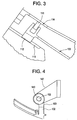
Figure 3 is detail view of the phantom line circle ofFigure 2 depicting a means of locating and positioning the transition piece and a forward sleeve during assembly; and -
Figure 4 is a schematic representation of an aft mounting bracket illustrating elongated slots to facilitate installation of the one-piece combustor liner ofFigure. 2 in accordance with an exemplary embodiment. - Referring to
FIG. 1 , a can-annular reverse-flow combustor 10 is illustrated. Thecombustor 10 generates the gases needed to drive the rotary motion of a turbine by combusting air and fuel within a confined space and discharging the resulting combustion gases through a stationary row of vanes, In operation,discharge air 11 from a compressor (compressed to a pressure on the order of about 176-281 tonnes/ m2 (250-400 lb/sq-in) reverses direction as it passes over the outside of the combustors (one shown at 14) and again as it enters the combustor en route to the turbine (first stage indicated at 16). Compressed air and fuel are burned in thecombustion chamber 18, producing gases with a temperature of about 1500° C or about 2730° F. These combustion gases flow at a high velocity intoturbine section 16 viatransition piece 20. Thetransition piece 20 connects to acombustor liner 24 atconnector 22, but in some applications, a discrete connector segment may be located between thetransition piece 20 and the combustor liner. As thedischarge air 11 flows over theoutside surface 26 of thetransition piece 20 andcombustor liner 24, it provides convective cooling to the combustor components. - In particular, there is an annular flow of the
discharge air 11 that is convectively processed over the outside surface 26 (cold side) ofliner 24. In an exemplary embodiment, the discharge air flows through a first flow sleeve 29 (e.g., impingement sleeve) and then asecond flow sleeve 28, which form anannular gap 30 so that the flow velocities can be sufficiently high to produce high heat transfer coefficients. The first and second flow sleeves 29 and 28, which are located at both thetransition piece 20 and thecombustor liner 24, respectively, are two separate sleeves connected together. Specifically, the impingement sleeve 29 (or, first flow sleeve) of thetransition piece 20 is received in a telescoping relationship in a mounting flange on the aft end of the combustor flow sleeve 28 (or, second flow sleeve), and thetransition piece 20 also receives thecombustor liner 24 in a telescoping relationship. Theimpingement sleeve 29 surrounds thetransition piece 20 forming a flow annulus 31 (or, first flow annulus) therebetween. Similarly, thecombustor flow sleeve 28 surrounds thecombustor liner 24 creating a flow annulus 30 (or, second flow annulus) therebetween. It can be seen from theflow arrow 32, that cross flow cooling air traveling in theannulus 31 continues to flow into theannulus 30 in a direction perpendicular to impingement cooling air flowing through cooling holes, slots, or other openings formed about the circumference of theflow sleeve 28 andimpingement sleeve 29. Theflow sleeve 28 andimpingement sleeve 29 have a series of holes, slots, or other openings (not shown) that allow thedischarge air 11 to move into theflow sleeve 28 andimpingement sleeve 29 at velocities that properly balance the competing requirements of high heat transfer and low pressure drop. - Can combustors are expensive because of their high parts count. The major parts as illustrated in
Figure 1 include acircular cap 34, anend cover 36 supporting a plurality of fuel nozzles 38, thecylindrical liner 24, thecylindrical flow sleeve 28, forward andaft pressure casings transition piece 20, and the impingement sleeve 29 controlling flow around thetransition piece 20. - In an exemplary embodiment referring to
Figure 2 , thecylindrical combustor liner 24 ofFigure 1 is eliminated, and atransition piece 120 transitions directly from a circular combustor head-end 100 to a turbine annulus sector 102 (corresponding to the first stage of the turbine indicated at 16) with a single piece. The singlepiece transition piece 120 may be formed from two halves or several components welded or joined together for ease of assembly or manufacture. Likewise, thefirst flow sleeve 28 is eliminated, and an impingement sleeve 129 transitions directly from the circular combustor head-end 100 to theaft frame 128 of thetransition piece 120 with a single piece. The singlepiece impingement sleeve 129 may be formed from two halves and welded or joined together for ease of assembly. The joint between theimpingement sleeve 129 and theaft frame 128 forms a substantially closed end to thecooling annulus 124. It should be noted that "single" also means multiple pieces joined together wherein the joining is by any appropriate means to join elements, and/or unitary, and/or one-piece, and the like. - The major components include, similar to the prior art: a
circular cap 134, anend cover 136 supporting a plurality offuel nozzles 138, thetransition piece 120 andimpingement sleeve 129. Thetransition piece 120 also supports aforward sleeve 122 that may be fixedly attached to thetransition piece 120 throughradial struts 124, e.g., by welding. Major components eliminated by this exemplary configuration include the forward andaft pressure cases cylindrical combustor liner 24, and thecylindrical flow sleeve 28 surroundingliner 24. Depending upon the configuration, other components not shown inFigure 1 may be eliminated such as outer crossfire tubes (since the crossfire tubes may be enclosed in the compressor discharge casing) and the transition piece support bracket, or "bullhorn bracket." - At the forward end, the combustor transition piece is supported on a
conventional hula seal 110 attached to thecap 134. More specifically,cap 134 is fitted with an associated compression-type seal 110, commonly referred to as a "hula seal", located betweentransition piece 120 andcap 134. In this configuration,cap 134 is fixedly mounted to endcover 136. While the above described exemplary embodiment is one solution that was worked out for one configuration of a gas turbine manufactured by the assignee of the present application, there are other conceivable configurations that would preserve the intent of a one-piece can combustor. For example, the hula seal could be inverted and attached to thetransition piece 120. In another example, theforward sleeve 122 is optionally integral withtransition piece 120, by casting, for example, but not limited thereto. - The arrangement described above provides location and support of the transition piece in operation using the
hula seal 110 joint with the fixedly-mountedcap assembly 134. During assembly of the combustion hardware, thecap 134 is not in place, and another means of support of the transition piece at its forward end is needed. The means of support is provided in accordance with an exemplary embodiment depicted in the detail view ofFigure 3 . Specifically, protrusions orkeys 112 are provided on the forward portion of theforward sleeve 122 that engage inkeyway slots 113 in the compressor casing, thereby locating and positioning the transition piece andforward sleeve 122 during assembly. Also at the forward end, apiston ring 111 slidingly engages anouter surface 114 of thecap 134 to seal against uncontrolled leakage of compressor discharge air past the impingement sleeve and flow sleeve assemblies. While the features shown inFigure 3 represent one embodiment of the invention, other configurations are conceivable that would satisfy the need for locating and sealing of the head-end of the one-piece can combustor. For example, thekeys 112 andkeyway slots 113 could be replaced by pins engaging slots (as depicted inFIG. 4 ) or holes in the compressor casing, or a conventional bracket with slidably-engaging slots on the transition piece are optionally employed. Similarly, the piston ring seal is optionally replaced by a hula seal. - While this invention is described in relation to a conventional can combustor with a round or circular head-end, it may be feasible or practical in some embodiments to form the head-end in a shape that is other than round or circular, including, for instance, an elliptical shape. Such alternative embodiments fall within the scope of this invention.
- In accordance with the disclosure, to be effective at its primary function, i.e., complete combustion with low emissions, the one piece can combustor configuration must present sufficient residence time to the hot gas to complete the combustion process without excessive CO formation, and the flow path must allow for adequate mixing of the burned gases to reduce the temperature non-uniformity entering the turbine. The configuration depicted in
Figure 2 has been shown analytically to be capable of accomplishing these goals without the added length of theliner 24 inFigure 1 . Features enabling a shorter length oftransition piece 120 inFigure 2 compared totransition piece 20 andliner 24 ofFigure 1 include a large-diameter head-end resulting in reduced bulk fluid velocity and increased residence time in the head-end, and flame temperature control using variable-geometry features of the remainder of the turbine. These variable-geometry features are not a part of this invention and are not discussed further here. Further marginal CO improvement is expected by a reduced surface area ofliner 24 andtransition piece 120, where reaction quenching normally takes place in the boundary layer, as well as reduced quenching associated with leakage and cooling flow in an interface betweentransition piece 20 andliner 24 with reference toFigure 1 . - It will be recognized by one skilled in the pertinent art that the mechanical assembly of the combustor is challenged with a single-piece construction, because there are fewer degrees of freedom of motion to accommodate dimensional stack up tolerances. More specifically, the circumferential positioning of the head-end of the transition piece must allow for stack up errors such that the support means at the head-end are not excessively statically loaded due to misalignments. In an exemplary embodiment referring to
Figure 4 , the allowance for circumferential assembly tolerances is made by a slight elongation of slots generally indicated at 140 in a mountingbracket 142 at the aft end, permitting slight side-to-side motion at the head-end 100. This feature is illustrated schematically inFigure 4 . More specifically,elongated slots 140 on either side of mountingbracket 142 allow fore-to-aft movement thereof when mounting theaft support lug 103 having or receiving mounting pins 152. The fore-to-aft movement ofaft end 102 oftransition piece 120 is limited by translation ofpins 152 in arespective slot 140. Hence, side-to-side motion of thehead end 100 of the transition piece is effected by moving one side ofpin 152 forward in thebracket 142, and the other side ofpin 152 aft in thebracket 142.Pin 152 may also be implemented as a bolt or bolts. - Advantages of exemplary embodiments of a one piece can combustor include application to existing turbine designs, low cost, improved performance, ease of assembly, and high reliability. Exemplary embodiments of the invention address the high cost of conventional can combustors by eliminating several major components. Exemplary embodiments of the invention also provide for better performance and emissions by reducing pressure losses and by reducing the exposure of the hot gas to relatively cold metal walls. A further advantage includes reduction of airflow used for cooling and leakage, since the joint between the transition piece and liner is eliminated. The reduced surface area decreases the heat pickup of the combustion air before it enters the flame zone, and reduces the CO quenching in the boundary layer. It is further envisioned that reliability is improved primarily as a result of the reduced parts count and the reduced number of rubbing interfaces. The one-piece can combustor configuration disclosed herein may be employed in the context of a standard or diffusion-type combustor without departing from the scope of the invention.
Claims (10)
- A can combustor for an industrial turbine comprising a transition piece (120) transitioning directly from a combustor head-end (100) to a turbine inlet (102) using a single piece transition piece (120);
characterised by:means for supporting the transition piece with a forward sleeve (122) during assembly, before a cap (134) is assembled thereto, said means for supporting including one of protrusions and keys (112) on a forward portion of said forward sleeve that engage in keyway slots (113) in the compressor casing. - The can combustor of claim 1, wherein the transition piece (120) is jointless.
- The can combustor of claim 1, further comprising an impingement sleeve (129) surrounding the transition piece (120), the impingement sleeve (129) having a plurality of cooling apertures formed about a circumference thereof receptive to directing cooling air from compressor discharge air (11) into a flow annulus (124) between the impingement sleeve (129) and the transition piece (120).
- The can combustor of claim 3, wherein the impingement sleeve (129) transitions directly from a combustor forward sleeve (122) to an aft frame (128) of the transition piece (120) using a single piece sleeve.
- The can combustor of claim 1, further comprising a mounting bracket (142) disposed at an aft end of the transition piece (120), the bracket having elongated slots (140) receptive to mounting pins (152) extending therethrough permitting side-to-side motion at a head end (100) of the transition piece (120).
- The can combustor of claim 5, wherein the bracket (142) includes a pair of the elongated slots (140) disposed at opposing sides of the bracket (142).
- The can combustor of claim 1, further comprising a hula seal (110) attached to an outer surface (114) of a cap (134).
- The can combustor of claim 7, wherein said hula seal (110) is receptive to engaging the head end (100) of the transition piece (120).
- The can combustor of claim 7, wherein the cap (34, 134) is fixedly mounted to an end cover (136) at the head end (100) of the combustor.
- The can combustor of claim 7, wherein said forward sleeve (122) is fixedly attached to the transition piece (120).
Applications Claiming Priority (1)
| Application Number | Priority Date | Filing Date | Title |
|---|---|---|---|
| US10/906,688 US7082766B1 (en) | 2005-03-02 | 2005-03-02 | One-piece can combustor |
Publications (2)
| Publication Number | Publication Date |
|---|---|
| EP1705427A1 EP1705427A1 (en) | 2006-09-27 |
| EP1705427B1 true EP1705427B1 (en) | 2009-07-01 |
Family
ID=36293366
Family Applications (1)
| Application Number | Title | Priority Date | Filing Date |
|---|---|---|---|
| EP06251027A Not-in-force EP1705427B1 (en) | 2005-03-02 | 2006-02-27 | One-piece can combustor |
Country Status (6)
| Country | Link |
|---|---|
| US (1) | US7082766B1 (en) |
| EP (1) | EP1705427B1 (en) |
| JP (1) | JP4694387B2 (en) |
| KR (1) | KR101240072B1 (en) |
| CN (1) | CN1828140B (en) |
| DE (1) | DE602006007507D1 (en) |
Families Citing this family (78)
| Publication number | Priority date | Publication date | Assignee | Title |
|---|---|---|---|---|
| JP2005171795A (en) * | 2003-12-09 | 2005-06-30 | Mitsubishi Heavy Ind Ltd | Gas turbine combustion equipment |
| US7010921B2 (en) * | 2004-06-01 | 2006-03-14 | General Electric Company | Method and apparatus for cooling combustor liner and transition piece of a gas turbine |
| US8769963B2 (en) * | 2007-01-30 | 2014-07-08 | Siemens Energy, Inc. | Low leakage spring clip/ring combinations for gas turbine engine |
| GB2449267A (en) * | 2007-05-15 | 2008-11-19 | Alstom Technology Ltd | Cool diffusion flame combustion |
| US7762075B2 (en) * | 2007-08-14 | 2010-07-27 | General Electric Company | Combustion liner stop in a gas turbine |
| JP5010521B2 (en) * | 2008-03-28 | 2012-08-29 | 三菱重工業株式会社 | Combustor transition piece guide jig, gas turbine combustor removal method, and manufacturing method |
| US20090249791A1 (en) * | 2008-04-08 | 2009-10-08 | General Electric Company | Transition piece impingement sleeve and method of assembly |
| US9038396B2 (en) * | 2008-04-08 | 2015-05-26 | General Electric Company | Cooling apparatus for combustor transition piece |
| US8096133B2 (en) * | 2008-05-13 | 2012-01-17 | General Electric Company | Method and apparatus for cooling and dilution tuning a gas turbine combustor liner and transition piece interface |
| US8087228B2 (en) * | 2008-09-11 | 2012-01-03 | General Electric Company | Segmented combustor cap |
| JP2010085052A (en) | 2008-10-01 | 2010-04-15 | Mitsubishi Heavy Ind Ltd | Combustor tail pipe, designing method therefor, and gas turbine |
| JP5173720B2 (en) * | 2008-10-01 | 2013-04-03 | 三菱重工業株式会社 | Combustor connection structure and gas turbine |
| US9822649B2 (en) * | 2008-11-12 | 2017-11-21 | General Electric Company | Integrated combustor and stage 1 nozzle in a gas turbine and method |
| US20100170258A1 (en) * | 2009-01-06 | 2010-07-08 | General Electric Company | Cooling apparatus for combustor transition piece |
| US20100170257A1 (en) * | 2009-01-08 | 2010-07-08 | General Electric Company | Cooling a one-piece can combustor and related method |
| US20100205972A1 (en) * | 2009-02-17 | 2010-08-19 | General Electric Company | One-piece can combustor with heat transfer surface enhacements |
| US7926283B2 (en) * | 2009-02-26 | 2011-04-19 | General Electric Company | Gas turbine combustion system cooling arrangement |
| US8438856B2 (en) * | 2009-03-02 | 2013-05-14 | General Electric Company | Effusion cooled one-piece can combustor |
| US8528336B2 (en) * | 2009-03-30 | 2013-09-10 | General Electric Company | Fuel nozzle spring support for shifting a natural frequency |
| US20100257863A1 (en) * | 2009-04-13 | 2010-10-14 | General Electric Company | Combined convection/effusion cooled one-piece can combustor |
| US8516822B2 (en) * | 2010-03-02 | 2013-08-27 | General Electric Company | Angled vanes in combustor flow sleeve |
| US8276391B2 (en) * | 2010-04-19 | 2012-10-02 | General Electric Company | Combustor liner cooling at transition duct interface and related method |
| US8307655B2 (en) | 2010-05-20 | 2012-11-13 | General Electric Company | System for cooling turbine combustor transition piece |
| GB201011854D0 (en) | 2010-07-14 | 2010-09-01 | Isis Innovation | Vane assembly for an axial flow turbine |
| US20120186269A1 (en) * | 2011-01-25 | 2012-07-26 | General Electric Company | Support between transition piece and impingement sleeve in combustor |
| US8887508B2 (en) * | 2011-03-15 | 2014-11-18 | General Electric Company | Impingement sleeve and methods for designing and forming impingement sleeve |
| US9249679B2 (en) | 2011-03-15 | 2016-02-02 | General Electric Company | Impingement sleeve and methods for designing and forming impingement sleeve |
| US8997501B2 (en) * | 2011-06-02 | 2015-04-07 | General Electric Company | System for mounting combustor transition piece to frame of gas turbine engine |
| US8915087B2 (en) | 2011-06-21 | 2014-12-23 | General Electric Company | Methods and systems for transferring heat from a transition nozzle |
| US8966910B2 (en) * | 2011-06-21 | 2015-03-03 | General Electric Company | Methods and systems for cooling a transition nozzle |
| US8448450B2 (en) * | 2011-07-05 | 2013-05-28 | General Electric Company | Support assembly for transition duct in turbine system |
| US8650852B2 (en) * | 2011-07-05 | 2014-02-18 | General Electric Company | Support assembly for transition duct in turbine system |
| US9103551B2 (en) | 2011-08-01 | 2015-08-11 | General Electric Company | Combustor leaf seal arrangement |
| EP2742291B1 (en) * | 2011-08-11 | 2020-07-08 | General Electric Company | System for injecting fuel in a gas turbine engine |
| CN104246373B (en) * | 2011-10-24 | 2016-06-08 | 阿尔斯通技术有限公司 | Combustion gas turbine |
| JP6029274B2 (en) * | 2011-11-10 | 2016-11-24 | 三菱日立パワーシステムズ株式会社 | Seal assembly and gas turbine provided with the same |
| US9188340B2 (en) * | 2011-11-18 | 2015-11-17 | General Electric Company | Gas turbine combustor endcover with adjustable flow restrictor and related method |
| US9435535B2 (en) * | 2012-02-20 | 2016-09-06 | General Electric Company | Combustion liner guide stop and method for assembling a combustor |
| US9291063B2 (en) * | 2012-02-29 | 2016-03-22 | Siemens Energy, Inc. | Mid-section of a can-annular gas turbine engine with an improved rotation of air flow from the compressor to the turbine |
| US9145778B2 (en) * | 2012-04-03 | 2015-09-29 | General Electric Company | Combustor with non-circular head end |
| US9109447B2 (en) * | 2012-04-24 | 2015-08-18 | General Electric Company | Combustion system including a transition piece and method of forming using a cast superalloy |
| US20130305739A1 (en) * | 2012-05-18 | 2013-11-21 | General Electric Company | Fuel nozzle cap |
| US9657949B2 (en) * | 2012-10-15 | 2017-05-23 | Pratt & Whitney Canada Corp. | Combustor skin assembly for gas turbine engine |
| US9316155B2 (en) | 2013-03-18 | 2016-04-19 | General Electric Company | System for providing fuel to a combustor |
| US10436445B2 (en) | 2013-03-18 | 2019-10-08 | General Electric Company | Assembly for controlling clearance between a liner and stationary nozzle within a gas turbine |
| US9322556B2 (en) | 2013-03-18 | 2016-04-26 | General Electric Company | Flow sleeve assembly for a combustion module of a gas turbine combustor |
| US9316396B2 (en) | 2013-03-18 | 2016-04-19 | General Electric Company | Hot gas path duct for a combustor of a gas turbine |
| US9383104B2 (en) | 2013-03-18 | 2016-07-05 | General Electric Company | Continuous combustion liner for a combustor of a gas turbine |
| US9360217B2 (en) | 2013-03-18 | 2016-06-07 | General Electric Company | Flow sleeve for a combustion module of a gas turbine |
| US9631812B2 (en) | 2013-03-18 | 2017-04-25 | General Electric Company | Support frame and method for assembly of a combustion module of a gas turbine |
| US9400114B2 (en) | 2013-03-18 | 2016-07-26 | General Electric Company | Combustor support assembly for mounting a combustion module of a gas turbine |
| CN104234859B (en) * | 2013-06-07 | 2016-08-31 | 常州兰翔机械有限责任公司 | A kind of manufacture method of gas turbine starter fuel cover |
| US11732892B2 (en) | 2013-08-14 | 2023-08-22 | General Electric Company | Gas turbomachine diffuser assembly with radial flow splitters |
| FR3022613B1 (en) * | 2014-06-24 | 2019-04-19 | Safran Helicopter Engines | BOSSAGE FOR COMBUSTION CHAMBER. |
| EP3002519B1 (en) | 2014-09-30 | 2020-05-27 | Ansaldo Energia Switzerland AG | Combustor arrangement with fastening system for combustor parts |
| CN104595926A (en) * | 2015-01-23 | 2015-05-06 | 北京华清燃气轮机与煤气化联合循环工程技术有限公司 | Integral combustion chamber for heat-channel components |
| US20160281992A1 (en) * | 2015-03-24 | 2016-09-29 | General Electric Company | Injection boss for a unibody combustor |
| US9945295B2 (en) * | 2015-06-01 | 2018-04-17 | United Technologies Corporation | Composite piston ring seal for axially and circumferentially translating ducts |
| US10197278B2 (en) * | 2015-09-02 | 2019-02-05 | General Electric Company | Combustor assembly for a turbine engine |
| US10371383B2 (en) * | 2017-01-27 | 2019-08-06 | General Electric Company | Unitary flow path structure |
| KR101984396B1 (en) | 2017-09-29 | 2019-05-30 | 두산중공업 주식회사 | Fuel nozzle, combustor and gas turbine having the same |
| KR102011903B1 (en) | 2017-10-27 | 2019-08-19 | 두산중공업 주식회사 | Fuel nozzle, combustor and gas turbine having the same |
| KR102049042B1 (en) | 2017-10-27 | 2019-11-26 | 두산중공업 주식회사 | Fuel nozzle assembly, combustor and gas turbine having the same |
| KR102046455B1 (en) | 2017-10-30 | 2019-11-19 | 두산중공업 주식회사 | Fuel nozzle, combustor and gas turbine having the same |
| KR102019091B1 (en) | 2017-10-31 | 2019-11-04 | 두산중공업 주식회사 | Fuel nozzle assembly, combustor and gas turbine having the same |
| KR102064295B1 (en) | 2017-10-31 | 2020-01-09 | 두산중공업 주식회사 | Fuel nozzle, combustor and gas turbine having the same |
| KR20190048905A (en) | 2017-10-31 | 2019-05-09 | 두산중공업 주식회사 | Fuel nozzle, combustor and gas turbine having the same |
| KR102021129B1 (en) | 2017-10-31 | 2019-11-04 | 두산중공업 주식회사 | Fuel nozzle, combustor and gas turbine having the same |
| KR102047368B1 (en) | 2017-10-31 | 2019-11-21 | 두산중공업 주식회사 | Fuel nozzle, combustor and gas turbine having the same |
| KR102047369B1 (en) | 2017-11-14 | 2019-11-21 | 두산중공업 주식회사 | Fuel nozzle, combustor and gas turbine having the same |
| CN108131399B (en) * | 2017-11-20 | 2019-06-28 | 北京动力机械研究所 | A kind of engine bearing seat cooling structure |
| KR102142140B1 (en) | 2018-09-17 | 2020-08-06 | 두산중공업 주식회사 | Fuel nozzle, combustor and gas turbine having the same |
| US11248797B2 (en) * | 2018-11-02 | 2022-02-15 | Chromalloy Gas Turbine Llc | Axial stop configuration for a combustion liner |
| US11377970B2 (en) | 2018-11-02 | 2022-07-05 | Chromalloy Gas Turbine Llc | System and method for providing compressed air to a gas turbine combustor |
| KR102226740B1 (en) | 2020-01-02 | 2021-03-11 | 두산중공업 주식회사 | Fuel nozzle, combustor and gas turbine having the same |
| US11371709B2 (en) | 2020-06-30 | 2022-06-28 | General Electric Company | Combustor air flow path |
| KR102460672B1 (en) | 2021-01-06 | 2022-10-27 | 두산에너빌리티 주식회사 | Fuel nozzle, fuel nozzle module and combustor having the same |
| GB202210143D0 (en) | 2022-07-11 | 2022-08-24 | Rolls Royce Plc | Combustor casing component for a gas turbine engine |
Family Cites Families (21)
| Publication number | Priority date | Publication date | Assignee | Title |
|---|---|---|---|---|
| GB1112131A (en) * | 1965-08-19 | 1968-05-01 | Lucas Industries Ltd | Gas turbine engine combustion apparatus |
| US4297842A (en) * | 1980-01-21 | 1981-11-03 | General Electric Company | NOx suppressant stationary gas turbine combustor |
| JPS62168932A (en) * | 1986-01-20 | 1987-07-25 | Hitachi Ltd | Gas turbine combustor |
| US5237813A (en) * | 1992-08-21 | 1993-08-24 | Allied-Signal Inc. | Annular combustor with outer transition liner cooling |
| GB2328011A (en) | 1997-08-05 | 1999-02-10 | Europ Gas Turbines Ltd | Combustor for gas or liquid fuelled turbine |
| JPH1183017A (en) * | 1997-09-08 | 1999-03-26 | Mitsubishi Heavy Ind Ltd | Combustor for gas turbine |
| US6098397A (en) * | 1998-06-08 | 2000-08-08 | Caterpillar Inc. | Combustor for a low-emissions gas turbine engine |
| US6494044B1 (en) * | 1999-11-19 | 2002-12-17 | General Electric Company | Aerodynamic devices for enhancing sidepanel cooling on an impingement cooled transition duct and related method |
| US6735950B1 (en) * | 2000-03-31 | 2004-05-18 | General Electric Company | Combustor dome plate and method of making the same |
| US6334310B1 (en) | 2000-06-02 | 2002-01-01 | General Electric Company | Fracture resistant support structure for a hula seal in a turbine combustor and related method |
| US6442946B1 (en) * | 2000-11-14 | 2002-09-03 | Power Systems Mfg., Llc | Three degrees of freedom aft mounting system for gas turbine transition duct |
| US6543233B2 (en) * | 2001-02-09 | 2003-04-08 | General Electric Company | Slot cooled combustor liner |
| US6606861B2 (en) * | 2001-02-26 | 2003-08-19 | United Technologies Corporation | Low emissions combustor for a gas turbine engine |
| JP2002317650A (en) * | 2001-04-24 | 2002-10-31 | Mitsubishi Heavy Ind Ltd | Gas turbine combustor |
| US6513331B1 (en) * | 2001-08-21 | 2003-02-04 | General Electric Company | Preferential multihole combustor liner |
| EP1288574A1 (en) * | 2001-09-03 | 2003-03-05 | Siemens Aktiengesellschaft | Combustion chamber arrangement |
| JP2003201863A (en) * | 2001-10-29 | 2003-07-18 | Mitsubishi Heavy Ind Ltd | Combustor and gas turbine with it |
| US6751961B2 (en) * | 2002-05-14 | 2004-06-22 | United Technologies Corporation | Bulkhead panel for use in a combustion chamber of a gas turbine engine |
| EP1413831A1 (en) * | 2002-10-21 | 2004-04-28 | Siemens Aktiengesellschaft | Annular combustor for a gas turbine and gas turbine |
| EP1426558A3 (en) * | 2002-11-22 | 2005-02-09 | General Electric Company | Gas turbine transition piece with dimpled surface and cooling method for such a transition piece |
| US6895761B2 (en) * | 2002-12-20 | 2005-05-24 | General Electric Company | Mounting assembly for the aft end of a ceramic matrix composite liner in a gas turbine engine combustor |
-
2005
- 2005-03-02 US US10/906,688 patent/US7082766B1/en active Active
-
2006
- 2006-02-27 DE DE602006007507T patent/DE602006007507D1/en active Active
- 2006-02-27 EP EP06251027A patent/EP1705427B1/en not_active Not-in-force
- 2006-02-28 KR KR1020060019711A patent/KR101240072B1/en not_active IP Right Cessation
- 2006-02-28 JP JP2006052424A patent/JP4694387B2/en not_active Expired - Fee Related
- 2006-03-02 CN CN2006100594081A patent/CN1828140B/en not_active Expired - Fee Related
Also Published As
| Publication number | Publication date |
|---|---|
| EP1705427A1 (en) | 2006-09-27 |
| JP4694387B2 (en) | 2011-06-08 |
| CN1828140B (en) | 2011-11-23 |
| DE602006007507D1 (en) | 2009-08-13 |
| KR20060096319A (en) | 2006-09-11 |
| KR101240072B1 (en) | 2013-03-06 |
| US7082766B1 (en) | 2006-08-01 |
| CN1828140A (en) | 2006-09-06 |
| JP2006242559A (en) | 2006-09-14 |
Similar Documents
| Publication | Publication Date | Title |
|---|---|---|
| EP1705427B1 (en) | One-piece can combustor | |
| US7010921B2 (en) | Method and apparatus for cooling combustor liner and transition piece of a gas turbine | |
| EP2481983B1 (en) | Turbulated Aft-End liner assembly and cooling method for gas turbine combustor | |
| US8141370B2 (en) | Methods and apparatus for radially compliant component mounting | |
| US5724816A (en) | Combustor for a gas turbine with cooling structure | |
| JP5374031B2 (en) | Apparatus and gas turbine engine for making it possible to reduce NOx emissions in a turbine engine | |
| JP4216052B2 (en) | Suppressive seal with thermal compliance | |
| US20090120093A1 (en) | Turbulated aft-end liner assembly and cooling method | |
| US7975487B2 (en) | Combustor assembly for gas turbine engine | |
| JP4675071B2 (en) | Combustor dome assembly of a gas turbine engine having an improved deflector plate | |
| EP3220047B1 (en) | Gas turbine flow sleeve mounting | |
| EP2642078B1 (en) | System and method for recirculating a hot gas flowing through a gas turbine | |
| EP2728263B1 (en) | A combustor | |
| JP2001289062A (en) | Wall surface cooling structure for gas turbine combustor | |
| EP2375160A2 (en) | Angled seal cooling system | |
| US20120304654A1 (en) | Combustion liner having turbulators | |
| US20190128523A1 (en) | Double skin combustor | |
| EP1426558A2 (en) | Gas turbine transition piece with dimpled surface and cooling method for such a transition piece | |
| US10508813B2 (en) | Gas turbine combustor cross fire tube assembly with opening restricting member and guide plates | |
| US20100300107A1 (en) | Method and flow sleeve profile reduction to extend combustor liner life | |
| US10837299B2 (en) | System and method for transition piece seal | |
| US9046038B2 (en) | Combustor | |
| US7578134B2 (en) | Methods and apparatus for assembling gas turbine engines | |
| US20180258789A1 (en) | System and method for transition piece seal |
Legal Events
| Date | Code | Title | Description |
|---|---|---|---|
| PUAI | Public reference made under article 153(3) epc to a published international application that has entered the european phase |
Free format text: ORIGINAL CODE: 0009012 |
|
| AK | Designated contracting states |
Kind code of ref document: A1 Designated state(s): AT BE BG CH CY CZ DE DK EE ES FI FR GB GR HU IE IS IT LI LT LU LV MC NL PL PT RO SE SI SK TR |
|
| AX | Request for extension of the european patent |
Extension state: AL BA HR MK YU |
|
| 17P | Request for examination filed |
Effective date: 20070327 |
|
| 17Q | First examination report despatched |
Effective date: 20070425 |
|
| AKX | Designation fees paid |
Designated state(s): CH DE FR GB IT LI |
|
| GRAP | Despatch of communication of intention to grant a patent |
Free format text: ORIGINAL CODE: EPIDOSNIGR1 |
|
| GRAS | Grant fee paid |
Free format text: ORIGINAL CODE: EPIDOSNIGR3 |
|
| GRAA | (expected) grant |
Free format text: ORIGINAL CODE: 0009210 |
|
| AK | Designated contracting states |
Kind code of ref document: B1 Designated state(s): CH DE FR GB IT LI |
|
| REG | Reference to a national code |
Ref country code: GB Ref legal event code: FG4D |
|
| REG | Reference to a national code |
Ref country code: CH Ref legal event code: EP Ref country code: CH Ref legal event code: NV Representative=s name: SERVOPATENT GMBH |
|
| REF | Corresponds to: |
Ref document number: 602006007507 Country of ref document: DE Date of ref document: 20090813 Kind code of ref document: P |
|
| PLBE | No opposition filed within time limit |
Free format text: ORIGINAL CODE: 0009261 |
|
| STAA | Information on the status of an ep patent application or granted ep patent |
Free format text: STATUS: NO OPPOSITION FILED WITHIN TIME LIMIT |
|
| 26N | No opposition filed |
Effective date: 20100406 |
|
| REG | Reference to a national code |
Ref country code: FR Ref legal event code: PLFP Year of fee payment: 11 |
|
| PGFP | Annual fee paid to national office [announced via postgrant information from national office to epo] |
Ref country code: CH Payment date: 20160226 Year of fee payment: 11 |
|
| PGFP | Annual fee paid to national office [announced via postgrant information from national office to epo] |
Ref country code: FR Payment date: 20160217 Year of fee payment: 11 Ref country code: GB Payment date: 20160226 Year of fee payment: 11 |
|
| REG | Reference to a national code |
Ref country code: CH Ref legal event code: PL |
|
| GBPC | Gb: european patent ceased through non-payment of renewal fee |
Effective date: 20170227 |
|
| PG25 | Lapsed in a contracting state [announced via postgrant information from national office to epo] |
Ref country code: LI Free format text: LAPSE BECAUSE OF NON-PAYMENT OF DUE FEES Effective date: 20170228 Ref country code: CH Free format text: LAPSE BECAUSE OF NON-PAYMENT OF DUE FEES Effective date: 20170228 |
|
| REG | Reference to a national code |
Ref country code: FR Ref legal event code: ST Effective date: 20171031 |
|
| PG25 | Lapsed in a contracting state [announced via postgrant information from national office to epo] |
Ref country code: FR Free format text: LAPSE BECAUSE OF NON-PAYMENT OF DUE FEES Effective date: 20170228 |
|
| PG25 | Lapsed in a contracting state [announced via postgrant information from national office to epo] |
Ref country code: GB Free format text: LAPSE BECAUSE OF NON-PAYMENT OF DUE FEES Effective date: 20170227 |
|
| PGFP | Annual fee paid to national office [announced via postgrant information from national office to epo] |
Ref country code: DE Payment date: 20200121 Year of fee payment: 15 Ref country code: IT Payment date: 20200121 Year of fee payment: 15 |
|
| REG | Reference to a national code |
Ref country code: DE Ref legal event code: R119 Ref document number: 602006007507 Country of ref document: DE |
|
| PG25 | Lapsed in a contracting state [announced via postgrant information from national office to epo] |
Ref country code: DE Free format text: LAPSE BECAUSE OF NON-PAYMENT OF DUE FEES Effective date: 20210901 |
|
| PG25 | Lapsed in a contracting state [announced via postgrant information from national office to epo] |
Ref country code: IT Free format text: LAPSE BECAUSE OF NON-PAYMENT OF DUE FEES Effective date: 20210227 |