EP1160512A2 - Fracture resistant support structure for a hula seal in a turbine combustor and related method - Google Patents
Fracture resistant support structure for a hula seal in a turbine combustor and related method Download PDFInfo
- Publication number
- EP1160512A2 EP1160512A2 EP01304762A EP01304762A EP1160512A2 EP 1160512 A2 EP1160512 A2 EP 1160512A2 EP 01304762 A EP01304762 A EP 01304762A EP 01304762 A EP01304762 A EP 01304762A EP 1160512 A2 EP1160512 A2 EP 1160512A2
- Authority
- EP
- European Patent Office
- Prior art keywords
- cooling sleeve
- combustion liner
- outer cooling
- liner
- sleeve
- Prior art date
- Legal status (The legal status is an assumption and is not a legal conclusion. Google has not performed a legal analysis and makes no representation as to the accuracy of the status listed.)
- Withdrawn
Links
Images
Classifications
-
- F—MECHANICAL ENGINEERING; LIGHTING; HEATING; WEAPONS; BLASTING
- F23—COMBUSTION APPARATUS; COMBUSTION PROCESSES
- F23R—GENERATING COMBUSTION PRODUCTS OF HIGH PRESSURE OR HIGH VELOCITY, e.g. GAS-TURBINE COMBUSTION CHAMBERS
- F23R3/00—Continuous combustion chambers using liquid or gaseous fuel
- F23R3/002—Wall structures
-
- F—MECHANICAL ENGINEERING; LIGHTING; HEATING; WEAPONS; BLASTING
- F01—MACHINES OR ENGINES IN GENERAL; ENGINE PLANTS IN GENERAL; STEAM ENGINES
- F01D—NON-POSITIVE DISPLACEMENT MACHINES OR ENGINES, e.g. STEAM TURBINES
- F01D9/00—Stators
- F01D9/02—Nozzles; Nozzle boxes; Stator blades; Guide conduits, e.g. individual nozzles
- F01D9/023—Transition ducts between combustor cans and first stage of the turbine in gas-turbine engines; their cooling or sealings
-
- F—MECHANICAL ENGINEERING; LIGHTING; HEATING; WEAPONS; BLASTING
- F23—COMBUSTION APPARATUS; COMBUSTION PROCESSES
- F23D—BURNERS
- F23D2214/00—Cooling
-
- Y—GENERAL TAGGING OF NEW TECHNOLOGICAL DEVELOPMENTS; GENERAL TAGGING OF CROSS-SECTIONAL TECHNOLOGIES SPANNING OVER SEVERAL SECTIONS OF THE IPC; TECHNICAL SUBJECTS COVERED BY FORMER USPC CROSS-REFERENCE ART COLLECTIONS [XRACs] AND DIGESTS
- Y10—TECHNICAL SUBJECTS COVERED BY FORMER USPC
- Y10T—TECHNICAL SUBJECTS COVERED BY FORMER US CLASSIFICATION
- Y10T29/00—Metal working
- Y10T29/49—Method of mechanical manufacture
- Y10T29/49229—Prime mover or fluid pump making
- Y10T29/4927—Cylinder, cylinder head or engine valve sleeve making
- Y10T29/49272—Cylinder, cylinder head or engine valve sleeve making with liner, coating, or sleeve
Definitions
- This invention relates to gas turbine combustors, and particularly to a fracture resistant support structure for a so-called "hula seal" between a combustion liner and a transition piece.
- the support structure is placed between the hula seal and combustion liner.
- the liner will expand more than the outer sleeve, and will therefore create compressive radial stresses at the interface, and tensile hoop stresses in the outer sleeve.
- the resulting thermally induced deformations cause hoop extension such that the outer sleeve diameter increases to the extent that the sleeve is permanently deformed.
- the liner contracts but the outer sleeve cannot return to its original diameter due to the permanently set deformation.
- the inability of the outer sleeve to recover its original shape creates a radial gap which acts as a crack opening displacement, impinging on the fillet weld. This crack opening displacement may increase the stress intensity factor to the critical stress intensity factor (KIC) in order to drive the crack into the weld.
- KIC critical stress intensity factor
- the outer sleeve is made slightly oversized to produce a radial gap between the liner and the outer sleeve at ambient temperature.
- the gap is calculated by considering the operating temperatures of both components and their respective thermal expansion coefficients. The calculated value is the value that will create no thermal mismatch stresses.
- the outer sleeve can be formed with the appropriate diameter. The aft end of the outer sleeve is swaged inwards an amount equal to the gap value to insure that the edge of the outer sleeve touches the liner. After welding prep is applied, the outer sleeve is welded over the liner.
- the crack tip that impinges on the fillet weld is no longer infinitely sharp. Rather, a blunt crack tip is provided that reduces the stress intensity factor in the weld, and thus reduces the propensity for cracking.
- the outer sleeve may be separated into multiple segments at the welded end. Each segment is welded with an independent fillet weld so that the fracture energy in each segment is limited, and the segments are flexible during thermal growth. These segments are positioned with respect to axial slots in the liner and the in respective cooling holes in the outer sleeve.
- the axial channels in the liner are completely covered by the outer sleeve.
- the air inlet holes in the outer sleeve are placed over a circumferential channel which acts as a plenum and feeds air into the axial channels.
- the axial channels extend beyond the length of the outer sleeve.
- the exposed length of the axial channels provides air inlet locations, thus replacing the inlet holes of the previous design.
- the number or location of the segments can be independent of the number and location of the axial channels and the location of air inlet holes.
- the present invention relates to a combustion liner and outer cooling sleeve assembly for a turbine combustor comprising a substantially cylindrical combustion liner having a forward end and an aft end; and a substantially cylindrical outer cooling sleeve surrounding at least an axial portion of the combustion liner; wherein the outer cooling sleeve is secured to the combustion liner by a weld at an end of the outer cooling sleeve, with a predetermined radial gap between the combustion liner and the outer cooling sleeve extending at least partially about the combustion liner, the radial gap determined by respective operating temperatures and thermal expansion coefficients of the combustion liner and the outer cooling sleeve.
- the invention in another aspect, relates to a combustion liner and cooling sleeve assembly for a turbine combustor comprising a substantially cylindrical combustion liner; and a substantially cylindrical cooling sleeve surrounding at least an axial portion of the combustion liner; wherein the outer cooling sleeve is secured to the combustion liner by a weld at one end of the outer cooling sleeve, with a predetermined radial gap between the combustion liner and the cooling sleeve; wherein the end is circumferentially divided into segments and wherein the weld is continuous in each segment; and further wherein the end is swaged radially inwardly an amount equal to the radial gap such that the end engages an outer surface of the combustion liner.
- the invention provides a method of reducing crack propensity in a substantially cylindrical combustion liner and substantially cylindrical outer cooling sleeve assembly where one end of the outer cooling sleeve is welded to the combustion liner, the method comprising a) determining a radial gap between the combination liner and the outer cooling sleeve as a function of operating temperatures and thermal expansion coefficients of the combustion liner and the cooling sleeve; b) forming the outer cooling sleeve with a diameter sufficient to provide the radial gap; c) swaging the end of the outer cooling sleeve to bring the end into engagement with the combustion liner; and d) welding the outer cooling sleeve to the combustion liner about the end.
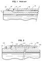
- Figure 1 illustrates, in partial section, the aft end of a current combustor liner 10 and a surrounding outer cooling sleeve 12.
- the radially outer cooling sleeve 12 is provided with a circumferentially arranged row of cooling holes 14 (one shown but two or more rows can be utilized) that permits cooling air to impinge on the liner 10.
- the liner 10 is provided with a circumferential groove 16 in axial alignment with the row of cooling holes 14, and a plurality of axially extending, circumferentially spaced cooling channels 18 communicate at one end with the groove 16.
- the outer cooling sleeve 12 is attached to the liner with a circumferential fillet weld 20 which may be an intermittent or "stitch" weld, or a continuous 360° weld.
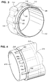
- FIG. 2 and 3 an exemplary embodiment of this invention is illustrated and, for convenience, certain reference numerals similar to those in Figure 1, but with the prefix "1" added, are used to identify corresponding components.
- the combustion liner 110 is surrounded by an outer cooling sleeve 112.
- a circumferential row of cooling holes 114 supply cooling air to the liner, the air impinging on a circumferential cooling groove 116 that supplies air to the axially extending cooling channels 118.
- the outer sleeve 112 is made slightly oversize, creating a radial air gap 124 between the liner and the sleeve.
- welding prep is applied, based on the fillet weld size, and the outer sleeve 112 is welded over the liner, with weld 120 either a continuous 360° weld, or an intermittent stitch weld as best seen in Figure 3.
- the crack tip 122 that impinges on the fillet weld is blunt, reducing the stress intensity factor in the weld, and thus reducing the propensity for cracking.
- the radial gap 124 between the combustion liner 110 and the outer cooling sleeve 112 is calculated by considering the operating temperatures of both components and their respective thermal expansion coefficients (the latter may be the same or different).
- the combustion liner 110 expands more than the outer cooling sleeve 112. This is so even if the thermal expansion coefficients are the same, because the liner 110 is considerably hotter (e.g., 1400°F vs. 900°F).
- the radial gap 124 provides room for thermal growth. As the combustion liner 110 expands, the gap will close, but not entirely, leaving a residual gap. As a result, the outer cooling sleeve 112 is not deformed and both components regain substantially their original shapes upon cooling. This factor, along with the smooth bend at the weld 120 and the blunt crack tip geometry at 122, significantly reduces the likelihood of cracking.
- the radial gap 124 need not extend a full 360° between the liner 110 and sleeve 112.
- the liner 110 and sleeve could be configured to create for example, a radial gap that extends only 180° (or any other suitable extent).
- the stitch weld 120 is interrupted by axial slots 125 originating in certain of the cooling holes 114, and defining the segments 126.
- the weld 120 is continuous within each segment, and the number of segments may vary (preferably four or more). Separating the forward end of the outer cooling sleeve 112 into multiple segments increases the flexibility of the weld connection. Separation also decreases the tendency for weld cracking because less elastic strain energy becomes available to the crack tip.
- a circumferential groove 116 it will be appreciated that it is not necessary to align the cooling holes 114 with the axially extending channels 118.
- Figure 4 illustrates a similar arrangement, but where the segments 226 of the outer cooling sleeve 212 are defined by notches or cut-outs 225. Radially inward of the segment cut-outs 225 are axial cooling channels 218 which extend axially forward and rearward of the stitch weld 220. These channels may communicate with a circumferential cooling groove 216 in the combustion liner 210.
- a preferably segmented centering ridge 128 may be machined in the outer surface of the combustion liner 110 or, alternatively, machined on the inner surface of the outer cooling sleeve 112. While there may be some localized deformation of the outer cooling sleeve 112 as the combustion liner 110 expands, it will not directly affect the remote weld 120.
- the ridge can also have an optional stop portion 130 that will prevent excessive axial movement of the outer cooling sleeve in the event of weld failure.
Landscapes
- Engineering & Computer Science (AREA)
- Mechanical Engineering (AREA)
- General Engineering & Computer Science (AREA)
- Chemical & Material Sciences (AREA)
- Combustion & Propulsion (AREA)
- Turbine Rotor Nozzle Sealing (AREA)
Abstract
Description
- Liner Material = Nimonic 263
- Liner Temperature = 1350 deg. F.
- Thermal Expansion at Temp = 8.4e-6 in/in
- Liner Young's Mod = 24e6 psi
- Liner Thickness (effective) = 0.125" for 7FA,
Crack Opening Displacement (COD), Radial Gap = (14/2) * (8.4e-6 * (1400-70) - 7.4e-6 *(850-70)) = 0.0378 in.
Claims (10)
- A combustion liner and outer cooling sleeve assembly for a turbine combustor comprising:a substantially cylindrical combustion liner (110, 210) having a forward end and an aft end; anda substantially cylindrical outer cooling sleeve (112, 212) surrounding at least an axial portion of said combustion liner; wherein said outer cooling sleeve is secured to said combustion liner by a weld (120, 220) at an end of said outer cooling sleeve, with a predetermined radial gap (124, 224) between said combustion liner and said outer cooling sleeve extending at least partially about said combustion liner, said radial gap determined by respective operating temperatures and thermal expansion coefficients of said combustion liner and said outer cooling sleeve.
- A combustion liner and cooling sleeve assembly for a turbine combustor comprising:a substantially cylindrical combustion liner (110, 210); anda substantially cylindrical cooling sleeve (112, 212) surrounding at least an axial portion of said combustion liner; wherein said outer cooling sleeve is secured to said combustion liner by a weld (120, 220) at one end of said outer cooling sleeve, with a predetermined radial gap (124, 224) between said combustion liner and said outer cooling sleeve; wherein said end is circumferentially divided into segments (126, 226) and wherein said weld (120, 220) is continuous in each segment; and further wherein said end is swaged radially inwardly an amount equal to said radial gap (124, 224 such that said end engages an outer surface of said combustion liner (110, 210)
- The assembly of claim 1 or claim 2 wherein said outer cooling sleeve (112) has at least one circumferentially arranged row of cooling holes (114) adjacent said end.
- The assembly of any preceding claim wherein said combustion liner (112) has a circumferentially extending cooling groove (116) substantially axially aligned with said at least one row of cooling holes (114).
- The assembly of claim 4 wherein said liner (110) is provided with one or more axially extending cooling channels (118) communicating with said cooling groove (116).
- The assembly of claim 2 wherein said segments (126) are defined by axially extending slots (125).
- A method of reducing crack propensity in a substantially cylindrical combustion liner (110, 210) and substantially cylindrical outer cooling sleeve (112, 212) assembly where one end of said outer cooling sleeve is welded to said combustion liner, the method comprising:a) determining a radial gap (124, 224) between said combination liner and said outer cooling sleeve (112, 212) as a function of operating temperatures and thermal expansion coefficients of said combustion liner and said outer cooling sleeve;b) forming said outer cooling sleeve (112, 212) with a diameter sufficient to provide said radial gap (124, 224);c) swaging said end of said outer cooling sleeve (112, 212) to bring said end into engagement with said combustion liner; andd) welding said cooling sleeve (112, 212) to said liner about said end.
- The method of claim 7 wherein said radial gap (124, 224) is sufficiently large so that, during operation, a residual gap will be maintained between said combustion liner and said outer cooling sleeve (112).
- The method of claim 7 wherein said thermal expansion coefficients are identical.
- The method of claim 7 wherein said weld (120, 220) is a continuous 360° weld about said edge.
Applications Claiming Priority (2)
| Application Number | Priority Date | Filing Date | Title |
|---|---|---|---|
| US586043 | 2000-06-02 | ||
| US09/586,043 US6334310B1 (en) | 2000-06-02 | 2000-06-02 | Fracture resistant support structure for a hula seal in a turbine combustor and related method |
Publications (2)
| Publication Number | Publication Date |
|---|---|
| EP1160512A2 true EP1160512A2 (en) | 2001-12-05 |
| EP1160512A3 EP1160512A3 (en) | 2002-06-19 |
Family
ID=24344065
Family Applications (1)
| Application Number | Title | Priority Date | Filing Date |
|---|---|---|---|
| EP01304762A Withdrawn EP1160512A3 (en) | 2000-06-02 | 2001-05-31 | Fracture resistant support structure for a hula seal in a turbine combustor and related method |
Country Status (3)
| Country | Link |
|---|---|
| US (1) | US6334310B1 (en) |
| EP (1) | EP1160512A3 (en) |
| JP (1) | JP2002089843A (en) |
Cited By (5)
| Publication number | Priority date | Publication date | Assignee | Title |
|---|---|---|---|---|
| EP1705427A1 (en) | 2005-03-02 | 2006-09-27 | General Electric Company | One-piece can combustor |
| US7155800B2 (en) | 2005-02-24 | 2007-01-02 | General Electric Company | Automated seal strip assembly method and apparatus for rotary machines |
| WO2007106087A1 (en) * | 2006-03-14 | 2007-09-20 | United Technologies Corporation | Crack resistant combustor |
| US7284378B2 (en) | 2004-06-04 | 2007-10-23 | General Electric Company | Methods and apparatus for low emission gas turbine energy generation |
| CN104246373A (en) * | 2011-10-24 | 2014-12-24 | 阿尔斯通技术有限公司 | Gas turbine |
Families Citing this family (30)
| Publication number | Priority date | Publication date | Assignee | Title |
|---|---|---|---|---|
| US6722134B2 (en) | 2002-09-18 | 2004-04-20 | General Electric Company | Linear surface concavity enhancement |
| US6761031B2 (en) | 2002-09-18 | 2004-07-13 | General Electric Company | Double wall combustor liner segment with enhanced cooling |
| US7104067B2 (en) * | 2002-10-24 | 2006-09-12 | General Electric Company | Combustor liner with inverted turbulators |
| US6681578B1 (en) | 2002-11-22 | 2004-01-27 | General Electric Company | Combustor liner with ring turbulators and related method |
| US7186084B2 (en) * | 2003-11-19 | 2007-03-06 | General Electric Company | Hot gas path component with mesh and dimpled cooling |
| US6984102B2 (en) * | 2003-11-19 | 2006-01-10 | General Electric Company | Hot gas path component with mesh and turbulated cooling |
| US7096668B2 (en) * | 2003-12-22 | 2006-08-29 | Martling Vincent C | Cooling and sealing design for a gas turbine combustion system |
| US7082770B2 (en) * | 2003-12-24 | 2006-08-01 | Martling Vincent C | Flow sleeve for a low NOx combustor |
| US7007482B2 (en) * | 2004-05-28 | 2006-03-07 | Power Systems Mfg., Llc | Combustion liner seal with heat transfer augmentation |
| US7269957B2 (en) * | 2004-05-28 | 2007-09-18 | Martling Vincent C | Combustion liner having improved cooling and sealing |
| US7010921B2 (en) * | 2004-06-01 | 2006-03-14 | General Electric Company | Method and apparatus for cooling combustor liner and transition piece of a gas turbine |
| US7246995B2 (en) * | 2004-12-10 | 2007-07-24 | Siemens Power Generation, Inc. | Seal usable between a transition and a turbine vane assembly in a turbine engine |
| US7524167B2 (en) * | 2006-05-04 | 2009-04-28 | Siemens Energy, Inc. | Combustor spring clip seal system |
| US7802431B2 (en) * | 2006-07-27 | 2010-09-28 | Siemens Energy, Inc. | Combustor liner with reverse flow for gas turbine engine |
| US8051663B2 (en) | 2007-11-09 | 2011-11-08 | United Technologies Corp. | Gas turbine engine systems involving cooling of combustion section liners |
| US8096133B2 (en) * | 2008-05-13 | 2012-01-17 | General Electric Company | Method and apparatus for cooling and dilution tuning a gas turbine combustor liner and transition piece interface |
| US8186167B2 (en) * | 2008-07-07 | 2012-05-29 | General Electric Company | Combustor transition piece aft end cooling and related method |
| US7926283B2 (en) * | 2009-02-26 | 2011-04-19 | General Electric Company | Gas turbine combustion system cooling arrangement |
| US8528336B2 (en) | 2009-03-30 | 2013-09-10 | General Electric Company | Fuel nozzle spring support for shifting a natural frequency |
| US8429919B2 (en) | 2009-05-28 | 2013-04-30 | General Electric Company | Expansion hula seals |
| KR101107460B1 (en) | 2009-06-23 | 2012-01-19 | 연세대학교 산학협력단 | Joint assembly of gas turbine combustor and manufacturing method thereof. |
| ES2571107T3 (en) * | 2010-03-16 | 2016-05-24 | Nelson Irrigation Corp | Pressure regulator housing assembly |
| US8276391B2 (en) * | 2010-04-19 | 2012-10-02 | General Electric Company | Combustor liner cooling at transition duct interface and related method |
| US8955330B2 (en) | 2011-03-29 | 2015-02-17 | Siemens Energy, Inc. | Turbine combustion system liner |
| US9103551B2 (en) | 2011-08-01 | 2015-08-11 | General Electric Company | Combustor leaf seal arrangement |
| EP2742291B1 (en) * | 2011-08-11 | 2020-07-08 | General Electric Company | System for injecting fuel in a gas turbine engine |
| US9046038B2 (en) | 2012-08-31 | 2015-06-02 | General Electric Company | Combustor |
| US8684130B1 (en) | 2012-09-10 | 2014-04-01 | Alstom Technology Ltd. | Damping system for combustor |
| CN104949153B (en) * | 2014-03-31 | 2017-09-26 | 北京航天动力研究所 | A kind of the high compression combustion chamber coolant jacket import and export mix and its processing method |
| US11859818B2 (en) * | 2019-02-25 | 2024-01-02 | General Electric Company | Systems and methods for variable microchannel combustor liner cooling |
Family Cites Families (8)
| Publication number | Priority date | Publication date | Assignee | Title |
|---|---|---|---|---|
| US3652181A (en) * | 1970-11-23 | 1972-03-28 | Carl F Wilhelm Jr | Cooling sleeve for gas turbine combustor transition member |
| US3938323A (en) * | 1971-12-15 | 1976-02-17 | Phillips Petroleum Company | Gas turbine combustor with controlled fuel mixing |
| DE3663847D1 (en) * | 1985-06-07 | 1989-07-13 | Ruston Gas Turbines Ltd | Combustor for gas turbine engine |
| FR2599821B1 (en) * | 1986-06-04 | 1988-09-02 | Snecma | COMBUSTION CHAMBER FOR TURBOMACHINES WITH MIXING HOLES PROVIDING THE POSITIONING OF THE HOT WALL ON THE COLD WALL |
| US5024058A (en) * | 1989-12-08 | 1991-06-18 | Sundstrand Corporation | Hot gas generator |
| US5349817A (en) * | 1993-11-12 | 1994-09-27 | Benteler Industries, Inc. | Air gap manifold port flange connection |
| US5724816A (en) * | 1996-04-10 | 1998-03-10 | General Electric Company | Combustor for a gas turbine with cooling structure |
| GB2328011A (en) * | 1997-08-05 | 1999-02-10 | Europ Gas Turbines Ltd | Combustor for gas or liquid fuelled turbine |
-
2000
- 2000-06-02 US US09/586,043 patent/US6334310B1/en not_active Expired - Fee Related
-
2001
- 2001-05-31 EP EP01304762A patent/EP1160512A3/en not_active Withdrawn
- 2001-06-01 JP JP2001165972A patent/JP2002089843A/en not_active Withdrawn
Cited By (9)
| Publication number | Priority date | Publication date | Assignee | Title |
|---|---|---|---|---|
| US7284378B2 (en) | 2004-06-04 | 2007-10-23 | General Electric Company | Methods and apparatus for low emission gas turbine energy generation |
| US7155800B2 (en) | 2005-02-24 | 2007-01-02 | General Electric Company | Automated seal strip assembly method and apparatus for rotary machines |
| EP1705427A1 (en) | 2005-03-02 | 2006-09-27 | General Electric Company | One-piece can combustor |
| CN1828140B (en) * | 2005-03-02 | 2011-11-23 | 通用电气公司 | One-piece can combustor |
| WO2007106087A1 (en) * | 2006-03-14 | 2007-09-20 | United Technologies Corporation | Crack resistant combustor |
| US9476591B2 (en) | 2006-03-14 | 2016-10-25 | United Technologies Corporation | Crack resistant combustor |
| CN104246373A (en) * | 2011-10-24 | 2014-12-24 | 阿尔斯通技术有限公司 | Gas turbine |
| CN104246373B (en) * | 2011-10-24 | 2016-06-08 | 阿尔斯通技术有限公司 | Combustion gas turbine |
| US9708920B2 (en) | 2011-10-24 | 2017-07-18 | General Electric Technology Gmbh | Gas turbine support element permitting thermal expansion between combustor shell and rotor cover at turbine inlet |
Also Published As
| Publication number | Publication date |
|---|---|
| JP2002089843A (en) | 2002-03-27 |
| US6334310B1 (en) | 2002-01-01 |
| EP1160512A3 (en) | 2002-06-19 |
Similar Documents
| Publication | Publication Date | Title |
|---|---|---|
| US6334310B1 (en) | Fracture resistant support structure for a hula seal in a turbine combustor and related method | |
| US6568187B1 (en) | Effusion cooled transition duct | |
| EP0801210B1 (en) | Gas turbine combustor wall cooling | |
| CA2604278C (en) | Method of manufacturing a heat shield for a fuel manifold | |
| US6904757B2 (en) | Mounting assembly for the forward end of a ceramic matrix composite liner in a gas turbine engine combustor | |
| EP1316677B1 (en) | Thermally compliant discourager seal | |
| US7052234B2 (en) | Turbine vane collar seal | |
| US7043921B2 (en) | Tube cooled combustor | |
| EP1443190A1 (en) | Mounting assembly for igniter in a gas turbine engine combustor having a ceramic matrix composite liner | |
| CN106968725A (en) | Apparatus and method for preventing the air between multiple turbine components from leaking | |
| US11619387B2 (en) | Liner for a combustor of a gas turbine engine with metallic corrugated member | |
| JP4812553B2 (en) | Thermal alignment clip | |
| EP2657606A2 (en) | A combustor and a method for repairing the combustor | |
| EP0503018B1 (en) | Gas turbine combustion system | |
| EP0972993A2 (en) | Crossfire tube for gas turbine combustors | |
| JP4912786B2 (en) | Thermally matched turbine shroud mounting assembly | |
| JP4266754B2 (en) | Assembly cowl for gas turbine engine dual annular combustor and its fabrication method. | |
| EP2532836A2 (en) | Combustion liner and transistion piece | |
| CA2935760C (en) | Gas turbine engine combustor and method of forming same | |
| US20060162314A1 (en) | Cooling system for a transition bracket of a transition in a turbine engine | |
| JP2010185438A (en) | Combustor liner unit and method of assembling combustor liner unit |
Legal Events
| Date | Code | Title | Description |
|---|---|---|---|
| PUAI | Public reference made under article 153(3) epc to a published international application that has entered the european phase |
Free format text: ORIGINAL CODE: 0009012 |
|
| AK | Designated contracting states |
Kind code of ref document: A2 Designated state(s): AT BE CH CY DE DK ES FI FR GB GR IE IT LI LU MC NL PT SE TR |
|
| AX | Request for extension of the european patent |
Free format text: AL;LT;LV;MK;RO;SI |
|
| PUAL | Search report despatched |
Free format text: ORIGINAL CODE: 0009013 |
|
| AK | Designated contracting states |
Kind code of ref document: A3 Designated state(s): AT BE CH CY DE DK ES FI FR GB GR IE IT LI LU MC NL PT SE TR |
|
| AX | Request for extension of the european patent |
Free format text: AL;LT;LV;MK;RO;SI |
|
| 17P | Request for examination filed |
Effective date: 20021219 |
|
| AKX | Designation fees paid |
Designated state(s): CH DE FR GB IT LI |
|
| 17Q | First examination report despatched |
Effective date: 20030606 |
|
| STAA | Information on the status of an ep patent application or granted ep patent |
Free format text: STATUS: THE APPLICATION IS DEEMED TO BE WITHDRAWN |
|
| 18D | Application deemed to be withdrawn |
Effective date: 20031017 |