EP1705427B1 - Einteilige becherförmige Brennkammer - Google Patents
Einteilige becherförmige Brennkammer Download PDFInfo
- Publication number
- EP1705427B1 EP1705427B1 EP06251027A EP06251027A EP1705427B1 EP 1705427 B1 EP1705427 B1 EP 1705427B1 EP 06251027 A EP06251027 A EP 06251027A EP 06251027 A EP06251027 A EP 06251027A EP 1705427 B1 EP1705427 B1 EP 1705427B1
- Authority
- EP
- European Patent Office
- Prior art keywords
- combustor
- transition piece
- sleeve
- piece
- liner
- Prior art date
- Legal status (The legal status is an assumption and is not a legal conclusion. Google has not performed a legal analysis and makes no representation as to the accuracy of the status listed.)
- Not-in-force
Links
Images


Classifications
-
- F—MECHANICAL ENGINEERING; LIGHTING; HEATING; WEAPONS; BLASTING
- F23—COMBUSTION APPARATUS; COMBUSTION PROCESSES
- F23R—GENERATING COMBUSTION PRODUCTS OF HIGH PRESSURE OR HIGH VELOCITY, e.g. GAS-TURBINE COMBUSTION CHAMBERS
- F23R3/00—Continuous combustion chambers using liquid or gaseous fuel
- F23R3/02—Continuous combustion chambers using liquid or gaseous fuel characterised by the air-flow or gas-flow configuration
- F23R3/16—Continuous combustion chambers using liquid or gaseous fuel characterised by the air-flow or gas-flow configuration with devices inside the flame tube or the combustion chamber to influence the air or gas flow
- F23R3/18—Flame stabilising means, e.g. flame holders for after-burners of jet-propulsion plants
- F23R3/22—Flame stabilising means, e.g. flame holders for after-burners of jet-propulsion plants movable, e.g. to an inoperative position; adjustable, e.g. self-adjusting
-
- F—MECHANICAL ENGINEERING; LIGHTING; HEATING; WEAPONS; BLASTING
- F23—COMBUSTION APPARATUS; COMBUSTION PROCESSES
- F23R—GENERATING COMBUSTION PRODUCTS OF HIGH PRESSURE OR HIGH VELOCITY, e.g. GAS-TURBINE COMBUSTION CHAMBERS
- F23R3/00—Continuous combustion chambers using liquid or gaseous fuel
- F23R3/42—Continuous combustion chambers using liquid or gaseous fuel characterised by the arrangement or form of the flame tubes or combustion chambers
- F23R3/60—Support structures; Attaching or mounting means
-
- F—MECHANICAL ENGINEERING; LIGHTING; HEATING; WEAPONS; BLASTING
- F23—COMBUSTION APPARATUS; COMBUSTION PROCESSES
- F23R—GENERATING COMBUSTION PRODUCTS OF HIGH PRESSURE OR HIGH VELOCITY, e.g. GAS-TURBINE COMBUSTION CHAMBERS
- F23R3/00—Continuous combustion chambers using liquid or gaseous fuel
- F23R3/42—Continuous combustion chambers using liquid or gaseous fuel characterised by the arrangement or form of the flame tubes or combustion chambers
- F23R3/44—Combustion chambers comprising a single tubular flame tube within a tubular casing
-
- F—MECHANICAL ENGINEERING; LIGHTING; HEATING; WEAPONS; BLASTING
- F23—COMBUSTION APPARATUS; COMBUSTION PROCESSES
- F23R—GENERATING COMBUSTION PRODUCTS OF HIGH PRESSURE OR HIGH VELOCITY, e.g. GAS-TURBINE COMBUSTION CHAMBERS
- F23R3/00—Continuous combustion chambers using liquid or gaseous fuel
- F23R3/42—Continuous combustion chambers using liquid or gaseous fuel characterised by the arrangement or form of the flame tubes or combustion chambers
- F23R3/46—Combustion chambers comprising an annular arrangement of several essentially tubular flame tubes within a common annular casing or within individual casings
Definitions
- This invention relates generally to turbine components and more particularly to a combustion chamber.
- Industrial gas turbine combustors are typically designed as a plurality of discrete combustion chambers or “cans" in an array around the circumference of the turbine.
- the walls of an industrial gas turbine can combustion chamber are formed from two major pieces: a cylindrical or cone-shaped sheet metal liner engaging the round head end and a sheet metal transition piece that transitions the hot gas flowpath from the round cross-section of the liner to an arc-shaped sector of the inlet to the turbine. These two pieces are mated with a flexible joint, which requires some portion of compressor discharge air to be consumed in cooling flow and leakage at the joint.
- Dry Low NOx refers to lean premixed combustion systems with no diluents (e.g., water injection) for further flame temperature reduction.
- a low heat transfer rate from the cold side of the liner can lead to high liner surface temperatures and ultimately loss of strength.
- Several potential failure modes due to the high temperature of the liner include, but are not limited to, cracking, bulging and oxidation. These mechanisms shorten the life of the liner, requiring replacement of the part prematurely.
- conventional can combustors present a long flow path to the system, resulting in high pressure loss and long residence time of the hot gas. Long residence time is beneficial to CO reduction at low power, low temperature conditions, but is detrimental to NOx formation at high power, high temperature conditions.
- EP-A-0 896 193 discloses a combustor for a gas-or liquid-fuelled turbine having a compressor to supply air to the combustor for combustion and cooling.
- a combustion liner and cooling sleeve assembly for a turbine combustor includes a substantially cylindrical combustion liner and a substantially cylindrical outer cooling sleeve secured to the combustion liner by a weld.
- a can combustor that includes a transition piece transitioning directly from a combustor head-end to a turbine inlet using a single piece transition piece for an industrial turbine.
- the can combustor includes means for supporting the transition piece with a forward sleeve during assembly, before a cap is assembled thereto, said means for supporting including one of protrusions and keys on a forward portion of said forward sleeve that engage in keyway slots in the compressor casing.
- the transition piece is jointless.
- a can-annular reverse-flow combustor 10 is illustrated.
- the combustor 10 generates the gases needed to drive the rotary motion of a turbine by combusting air and fuel within a confined space and discharging the resulting combustion gases through a stationary row of vanes,
- discharge air 11 from a compressor (compressed to a pressure on the order of about 176-281 tonnes/ m 2 (250-400 lb/sq-in) reverses direction as it passes over the outside of the combustors (one shown at 14) and again as it enters the combustor en route to the turbine (first stage indicated at 16).
- Compressed air and fuel are burned in the combustion chamber 18, producing gases with a temperature of about 1500° C or about 2730° F. These combustion gases flow at a high velocity into turbine section 16 via transition piece 20.
- the transition piece 20 connects to a combustor liner 24 at connector 22, but in some applications, a discrete connector segment may be located between the transition piece 20 and the combustor liner. As the discharge air 11 flows over the outside surface 26 of the transition piece 20 and combustor liner 24, it provides convective cooling to the combustor components.
- the discharge air 11 there is an annular flow of the discharge air 11 that is convectively processed over the outside surface 26 (cold side) of liner 24.
- the discharge air flows through a first flow sleeve 29 (e.g., impingement sleeve) and then a second flow sleeve 28, which form an annular gap 30 so that the flow velocities can be sufficiently high to produce high heat transfer coefficients.
- the first and second flow sleeves 29 and 28, which are located at both the transition piece 20 and the combustor liner 24, respectively, are two separate sleeves connected together.
- the impingement sleeve 29 (or, first flow sleeve) of the transition piece 20 is received in a telescoping relationship in a mounting flange on the aft end of the combustor flow sleeve 28 (or, second flow sleeve), and the transition piece 20 also receives the combustor liner 24 in a telescoping relationship.
- the impingement sleeve 29 surrounds the transition piece 20 forming a flow annulus 31 (or, first flow annulus) therebetween.
- the combustor flow sleeve 28 surrounds the combustor liner 24 creating a flow annulus 30 (or, second flow annulus) therebetween.
- cross flow cooling air traveling in the annulus 31 continues to flow into the annulus 30 in a direction perpendicular to impingement cooling air flowing through cooling holes, slots, or other openings formed about the circumference of the flow sleeve 28 and impingement sleeve 29.
- the flow sleeve 28 and impingement sleeve 29 have a series of holes, slots, or other openings (not shown) that allow the discharge air 11 to move into the flow sleeve 28 and impingement sleeve 29 at velocities that properly balance the competing requirements of high heat transfer and low pressure drop.
- Can combustors are expensive because of their high parts count.
- the major parts as illustrated in Figure 1 include a circular cap 34, an end cover 36 supporting a plurality of fuel nozzles 38, the cylindrical liner 24, the cylindrical flow sleeve 28, forward and aft pressure casings 40 and 42, the transition piece 20, and the impingement sleeve 29 controlling flow around the transition piece 20.
- the cylindrical combustor liner 24 of Figure 1 is eliminated, and a transition piece 120 transitions directly from a circular combustor head-end 100 to a turbine annulus sector 102 (corresponding to the first stage of the turbine indicated at 16) with a single piece.
- the single piece transition piece 120 may be formed from two halves or several components welded or joined together for ease of assembly or manufacture.
- the first flow sleeve 28 is eliminated, and an impingement sleeve 129 transitions directly from the circular combustor head-end 100 to the aft frame 128 of the transition piece 120 with a single piece.
- the single piece impingement sleeve 129 may be formed from two halves and welded or joined together for ease of assembly.
- the joint between the impingement sleeve 129 and the aft frame 128 forms a substantially closed end to the cooling annulus 124.
- “single” also means multiple pieces joined together wherein the joining is by any appropriate means to join elements, and/or unitary, and/or one-piece, and the like.
- the major components include, similar to the prior art: a circular cap 134, an end cover 136 supporting a plurality of fuel nozzles 138, the transition piece 120 and impingement sleeve 129.
- the transition piece 120 also supports a forward sleeve 122 that may be fixedly attached to the transition piece 120 through radial struts 124, e.g., by welding.
- Major components eliminated by this exemplary configuration include the forward and aft pressure cases 40 and 42, respectively, the cylindrical combustor liner 24, and the cylindrical flow sleeve 28 surrounding liner 24.
- other components not shown in Figure 1 may be eliminated such as outer crossfire tubes (since the crossfire tubes may be enclosed in the compressor discharge casing) and the transition piece support bracket, or "bullhorn bracket.”
- the combustor transition piece is supported on a conventional hula seal 110 attached to the cap 134. More specifically, cap 134 is fitted with an associated compression-type seal 110, commonly referred to as a "hula seal", located between transition piece 120 and cap 134. In this configuration, cap 134 is fixedly mounted to end cover 136. While the above described exemplary embodiment is one solution that was worked out for one configuration of a gas turbine manufactured by the assignee of the present application, there are other conceivable configurations that would preserve the intent of a one-piece can combustor. For example, the hula seal could be inverted and attached to the transition piece 120. In another example, the forward sleeve 122 is optionally integral with transition piece 120, by casting, for example, but not limited thereto.
- the arrangement described above provides location and support of the transition piece in operation using the hula seal 110 joint with the fixedly-mounted cap assembly 134.
- the cap 134 is not in place, and another means of support of the transition piece at its forward end is needed.
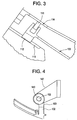
- the means of support is provided in accordance with an exemplary embodiment depicted in the detail view of Figure 3 .
- protrusions or keys 112 are provided on the forward portion of the forward sleeve 122 that engage in keyway slots 113 in the compressor casing, thereby locating and positioning the transition piece and forward sleeve 122 during assembly.
- a piston ring 111 slidingly engages an outer surface 114 of the cap 134 to seal against uncontrolled leakage of compressor discharge air past the impingement sleeve and flow sleeve assemblies.
- the keys 112 and keyway slots 113 could be replaced by pins engaging slots (as depicted in FIG. 4 ) or holes in the compressor casing, or a conventional bracket with slidably-engaging slots on the transition piece are optionally employed.
- the piston ring seal is optionally replaced by a hula seal.
- the one piece can combustor configuration must present sufficient residence time to the hot gas to complete the combustion process without excessive CO formation, and the flow path must allow for adequate mixing of the burned gases to reduce the temperature non-uniformity entering the turbine.
- the configuration depicted in Figure 2 has been shown analytically to be capable of accomplishing these goals without the added length of the liner 24 in Figure 1 .
- Features enabling a shorter length of transition piece 120 in Figure 2 compared to transition piece 20 and liner 24 of Figure 1 include a large-diameter head-end resulting in reduced bulk fluid velocity and increased residence time in the head-end, and flame temperature control using variable-geometry features of the remainder of the turbine.
- variable-geometry features are not a part of this invention and are not discussed further here.
- Further marginal CO improvement is expected by a reduced surface area of liner 24 and transition piece 120, where reaction quenching normally takes place in the boundary layer, as well as reduced quenching associated with leakage and cooling flow in an interface between transition piece 20 and liner 24 with reference to Figure 1 .
- elongated slots 140 on either side of mounting bracket 142 allow fore-to-aft movement thereof when mounting the aft support lug 103 having or receiving mounting pins 152.
- the fore-to-aft movement of aft end 102 of transition piece 120 is limited by translation of pins 152 in a respective slot 140.
- side-to-side motion of the head end 100 of the transition piece is effected by moving one side of pin 152 forward in the bracket 142, and the other side of pin 152 aft in the bracket 142.
- Pin 152 may also be implemented as a bolt or bolts.
- exemplary embodiments of a one piece can combustor include application to existing turbine designs, low cost, improved performance, ease of assembly, and high reliability.
- Exemplary embodiments of the invention address the high cost of conventional can combustors by eliminating several major components.
- Exemplary embodiments of the invention also provide for better performance and emissions by reducing pressure losses and by reducing the exposure of the hot gas to relatively cold metal walls.
- a further advantage includes reduction of airflow used for cooling and leakage, since the joint between the transition piece and liner is eliminated. The reduced surface area decreases the heat pickup of the combustion air before it enters the flame zone, and reduces the CO quenching in the boundary layer. It is further envisioned that reliability is improved primarily as a result of the reduced parts count and the reduced number of rubbing interfaces.
- the one-piece can combustor configuration disclosed herein may be employed in the context of a standard or diffusion-type combustor without departing from the scope of the invention.
Claims (10)
- Rohrbrennkammer für eine Industrieturbine mit einem Übergangsstück (120), das unter Anwendung eines einteiligen Übergangsstückes (120) direkt von einem Brennkammerkopfende (100) zu einem Turbineneinlass übergeht;
gekennzeichnet durch:Mittel zum Unterstützen des Übergangsstückes mit einer vorderen Hülse (122) während des Zusammenbaus, bevor eine Kappe (134) daran angebaut wird, wobei die Mittel zum Unterstützen eines von Vorsprüngen und Keilen (112) auf einem vorderen Abschnitt der vorderen Hülse beinhalten, die in Keilnutschlitzen (113) in dem Verdichtergehäuse eingreifen. - Rohrbrennkammer nach Anspruch 1, wobei das Übergangsstück (120) fugenlos ist.
- Rohrbrennkammer nach Anspruch 1, welche ferner eine das Übergangsstück (120) umgebende Prallhülse (129) aufweist, wobei die Prallhülse (129) mehrere um ihren Umfang herum ausgebildete zur Einführung von Kühlluft von der Verdichterauslassluft (11) in einen Strömungsringraum (124) zwischen der Prallhülse (122) und dem Übergangsstück (120) bereite Kühllöcher hat.
- Rohrbrennkammer nach Anspruch 3, wobei die Prallhülse (129) direkt von einer vorderen Hülse (122) der Brennkammer zu einem hinteren Rahmen (128) des Übergangsstückes (120) unter Anwendung einer einteiligen Hülse übergeht.
- Rohrbrennkammer nach Anspruch 1, welche ferner einen Befestigungsträger (142) aufweist, der an einem hinteren Ende des Übergangsstückes (120) angeordnet ist, wobei der Träger für die Aufnahme sich dadurch hindurch erstreckender Befestigungsstifte (152) bereite Längsschlitze (140) hat, die eine seitliche Bewegung an einem Kopfende (100) des Übergangsstückes (120) ermöglichen.
- Rohrbrennkammer nach Anspruch 5, wobei der Träger (142) ein Paar von den Längsschlitzen (140) enthält, die an gegenüberliegenden Seiten des Trägers (142) angeordnet sind.
- Rohrbrennkammer nach Anspruch 1, welche ferner eine Ringdichtung (110) aufweist, die an einer Außenoberfläche (114) einer Kappe (134) befestigt ist.
- Rohrbrennkammer nach Anspruch 7, wobei die Ringdichtung (110) für einen Eingriff mit dem Kopfende (100) des Übergangsstückes (120) bereit ist.
- Rohrbrennkammer nach Anspruch 7, wobei die Kappe (34, 134) fest an einer Endabdeckung (136) an dem Kopfende (100) der Brennkammer montiert ist.
- Rohrbrennkammer nach Anspruch 7, wobei die vordere Hülse (122) fest an dem Übergangsstück (120) angebracht ist.
Applications Claiming Priority (1)
| Application Number | Priority Date | Filing Date | Title |
|---|---|---|---|
| US10/906,688 US7082766B1 (en) | 2005-03-02 | 2005-03-02 | One-piece can combustor |
Publications (2)
| Publication Number | Publication Date |
|---|---|
| EP1705427A1 EP1705427A1 (de) | 2006-09-27 |
| EP1705427B1 true EP1705427B1 (de) | 2009-07-01 |
Family
ID=36293366
Family Applications (1)
| Application Number | Title | Priority Date | Filing Date |
|---|---|---|---|
| EP06251027A Not-in-force EP1705427B1 (de) | 2005-03-02 | 2006-02-27 | Einteilige becherförmige Brennkammer |
Country Status (6)
| Country | Link |
|---|---|
| US (1) | US7082766B1 (de) |
| EP (1) | EP1705427B1 (de) |
| JP (1) | JP4694387B2 (de) |
| KR (1) | KR101240072B1 (de) |
| CN (1) | CN1828140B (de) |
| DE (1) | DE602006007507D1 (de) |
Families Citing this family (78)
| Publication number | Priority date | Publication date | Assignee | Title |
|---|---|---|---|---|
| JP2005171795A (ja) * | 2003-12-09 | 2005-06-30 | Mitsubishi Heavy Ind Ltd | ガスタービン燃焼装置 |
| US7010921B2 (en) * | 2004-06-01 | 2006-03-14 | General Electric Company | Method and apparatus for cooling combustor liner and transition piece of a gas turbine |
| US8769963B2 (en) * | 2007-01-30 | 2014-07-08 | Siemens Energy, Inc. | Low leakage spring clip/ring combinations for gas turbine engine |
| GB2449267A (en) * | 2007-05-15 | 2008-11-19 | Alstom Technology Ltd | Cool diffusion flame combustion |
| US7762075B2 (en) * | 2007-08-14 | 2010-07-27 | General Electric Company | Combustion liner stop in a gas turbine |
| JP5010521B2 (ja) * | 2008-03-28 | 2012-08-29 | 三菱重工業株式会社 | 燃焼器尾筒案内治具及びガスタービンの燃焼器の取り外し方法、並びに製造方法 |
| US9038396B2 (en) * | 2008-04-08 | 2015-05-26 | General Electric Company | Cooling apparatus for combustor transition piece |
| US20090249791A1 (en) * | 2008-04-08 | 2009-10-08 | General Electric Company | Transition piece impingement sleeve and method of assembly |
| US8096133B2 (en) * | 2008-05-13 | 2012-01-17 | General Electric Company | Method and apparatus for cooling and dilution tuning a gas turbine combustor liner and transition piece interface |
| US8087228B2 (en) * | 2008-09-11 | 2012-01-03 | General Electric Company | Segmented combustor cap |
| JP2010085052A (ja) * | 2008-10-01 | 2010-04-15 | Mitsubishi Heavy Ind Ltd | 燃焼器尾筒およびその設計方法ならびにガスタービン |
| JP5173720B2 (ja) * | 2008-10-01 | 2013-04-03 | 三菱重工業株式会社 | 燃焼器接続構造およびガスタービン |
| US9822649B2 (en) * | 2008-11-12 | 2017-11-21 | General Electric Company | Integrated combustor and stage 1 nozzle in a gas turbine and method |
| US20100170258A1 (en) * | 2009-01-06 | 2010-07-08 | General Electric Company | Cooling apparatus for combustor transition piece |
| US20100170257A1 (en) * | 2009-01-08 | 2010-07-08 | General Electric Company | Cooling a one-piece can combustor and related method |
| US20100205972A1 (en) | 2009-02-17 | 2010-08-19 | General Electric Company | One-piece can combustor with heat transfer surface enhacements |
| US7926283B2 (en) * | 2009-02-26 | 2011-04-19 | General Electric Company | Gas turbine combustion system cooling arrangement |
| US8438856B2 (en) * | 2009-03-02 | 2013-05-14 | General Electric Company | Effusion cooled one-piece can combustor |
| US8528336B2 (en) * | 2009-03-30 | 2013-09-10 | General Electric Company | Fuel nozzle spring support for shifting a natural frequency |
| US20100257863A1 (en) * | 2009-04-13 | 2010-10-14 | General Electric Company | Combined convection/effusion cooled one-piece can combustor |
| US8516822B2 (en) * | 2010-03-02 | 2013-08-27 | General Electric Company | Angled vanes in combustor flow sleeve |
| US8276391B2 (en) | 2010-04-19 | 2012-10-02 | General Electric Company | Combustor liner cooling at transition duct interface and related method |
| US8307655B2 (en) | 2010-05-20 | 2012-11-13 | General Electric Company | System for cooling turbine combustor transition piece |
| GB201011854D0 (en) | 2010-07-14 | 2010-09-01 | Isis Innovation | Vane assembly for an axial flow turbine |
| US20120186269A1 (en) * | 2011-01-25 | 2012-07-26 | General Electric Company | Support between transition piece and impingement sleeve in combustor |
| US8887508B2 (en) * | 2011-03-15 | 2014-11-18 | General Electric Company | Impingement sleeve and methods for designing and forming impingement sleeve |
| US9249679B2 (en) | 2011-03-15 | 2016-02-02 | General Electric Company | Impingement sleeve and methods for designing and forming impingement sleeve |
| US8997501B2 (en) * | 2011-06-02 | 2015-04-07 | General Electric Company | System for mounting combustor transition piece to frame of gas turbine engine |
| US8915087B2 (en) | 2011-06-21 | 2014-12-23 | General Electric Company | Methods and systems for transferring heat from a transition nozzle |
| US8966910B2 (en) * | 2011-06-21 | 2015-03-03 | General Electric Company | Methods and systems for cooling a transition nozzle |
| US8650852B2 (en) * | 2011-07-05 | 2014-02-18 | General Electric Company | Support assembly for transition duct in turbine system |
| US8448450B2 (en) * | 2011-07-05 | 2013-05-28 | General Electric Company | Support assembly for transition duct in turbine system |
| US9103551B2 (en) | 2011-08-01 | 2015-08-11 | General Electric Company | Combustor leaf seal arrangement |
| WO2013022367A1 (en) * | 2011-08-11 | 2013-02-14 | General Electric Company | System for injecting fuel in a gas turbine engine |
| IN2014DN03773A (de) * | 2011-10-24 | 2015-07-10 | Alstom Technology Ltd | |
| JP6029274B2 (ja) * | 2011-11-10 | 2016-11-24 | 三菱日立パワーシステムズ株式会社 | シール組立体、及びこれを備えたガスタービン |
| US9188340B2 (en) * | 2011-11-18 | 2015-11-17 | General Electric Company | Gas turbine combustor endcover with adjustable flow restrictor and related method |
| US9435535B2 (en) | 2012-02-20 | 2016-09-06 | General Electric Company | Combustion liner guide stop and method for assembling a combustor |
| US9291063B2 (en) * | 2012-02-29 | 2016-03-22 | Siemens Energy, Inc. | Mid-section of a can-annular gas turbine engine with an improved rotation of air flow from the compressor to the turbine |
| US9145778B2 (en) * | 2012-04-03 | 2015-09-29 | General Electric Company | Combustor with non-circular head end |
| US9109447B2 (en) | 2012-04-24 | 2015-08-18 | General Electric Company | Combustion system including a transition piece and method of forming using a cast superalloy |
| US20130305739A1 (en) * | 2012-05-18 | 2013-11-21 | General Electric Company | Fuel nozzle cap |
| US9657949B2 (en) * | 2012-10-15 | 2017-05-23 | Pratt & Whitney Canada Corp. | Combustor skin assembly for gas turbine engine |
| US9383104B2 (en) | 2013-03-18 | 2016-07-05 | General Electric Company | Continuous combustion liner for a combustor of a gas turbine |
| US9322556B2 (en) | 2013-03-18 | 2016-04-26 | General Electric Company | Flow sleeve assembly for a combustion module of a gas turbine combustor |
| US9631812B2 (en) | 2013-03-18 | 2017-04-25 | General Electric Company | Support frame and method for assembly of a combustion module of a gas turbine |
| US9316155B2 (en) | 2013-03-18 | 2016-04-19 | General Electric Company | System for providing fuel to a combustor |
| US9316396B2 (en) | 2013-03-18 | 2016-04-19 | General Electric Company | Hot gas path duct for a combustor of a gas turbine |
| US9360217B2 (en) | 2013-03-18 | 2016-06-07 | General Electric Company | Flow sleeve for a combustion module of a gas turbine |
| US9400114B2 (en) | 2013-03-18 | 2016-07-26 | General Electric Company | Combustor support assembly for mounting a combustion module of a gas turbine |
| US10436445B2 (en) | 2013-03-18 | 2019-10-08 | General Electric Company | Assembly for controlling clearance between a liner and stationary nozzle within a gas turbine |
| CN104234859B (zh) * | 2013-06-07 | 2016-08-31 | 常州兰翔机械有限责任公司 | 一种燃气涡轮起动机用燃油盖的制造方法 |
| US11732892B2 (en) | 2013-08-14 | 2023-08-22 | General Electric Company | Gas turbomachine diffuser assembly with radial flow splitters |
| FR3022613B1 (fr) * | 2014-06-24 | 2019-04-19 | Safran Helicopter Engines | Bossage pour chambre de combustion. |
| EP3002519B1 (de) * | 2014-09-30 | 2020-05-27 | Ansaldo Energia Switzerland AG | Brennkammer mit befestigungssystem für brennkammerteile |
| CN104595926A (zh) * | 2015-01-23 | 2015-05-06 | 北京华清燃气轮机与煤气化联合循环工程技术有限公司 | 热通道部件一体燃烧室 |
| US20160281992A1 (en) * | 2015-03-24 | 2016-09-29 | General Electric Company | Injection boss for a unibody combustor |
| US9945295B2 (en) * | 2015-06-01 | 2018-04-17 | United Technologies Corporation | Composite piston ring seal for axially and circumferentially translating ducts |
| US10197278B2 (en) * | 2015-09-02 | 2019-02-05 | General Electric Company | Combustor assembly for a turbine engine |
| US10371383B2 (en) * | 2017-01-27 | 2019-08-06 | General Electric Company | Unitary flow path structure |
| KR101984396B1 (ko) | 2017-09-29 | 2019-05-30 | 두산중공업 주식회사 | 트랜지션 피스, 이를 포함하는 연소기 및 가스 터빈 |
| KR102049042B1 (ko) | 2017-10-27 | 2019-11-26 | 두산중공업 주식회사 | 연료 노즐 조립체, 이를 포함하는 연소기 및 가스 터빈 |
| KR102011903B1 (ko) | 2017-10-27 | 2019-08-19 | 두산중공업 주식회사 | 연료 노즐, 이를 포함하는 연소기 및 가스 터빈 |
| KR102046455B1 (ko) | 2017-10-30 | 2019-11-19 | 두산중공업 주식회사 | 연료 노즐, 이를 포함하는 연소기 및 가스 터빈 |
| KR102019091B1 (ko) | 2017-10-31 | 2019-11-04 | 두산중공업 주식회사 | 연료 노즐 조립체, 이를 포함하는 연소기 및 가스 터빈 |
| KR20190048905A (ko) | 2017-10-31 | 2019-05-09 | 두산중공업 주식회사 | 연료 노즐, 이를 포함하는 연소기 및 가스 터빈 |
| KR102064295B1 (ko) | 2017-10-31 | 2020-01-09 | 두산중공업 주식회사 | 연료 노즐, 이를 포함하는 연소기 및 가스 터빈 |
| KR102021129B1 (ko) | 2017-10-31 | 2019-11-04 | 두산중공업 주식회사 | 연료 노즐, 이를 포함하는 연소기 및 가스 터빈 |
| KR102047368B1 (ko) | 2017-10-31 | 2019-11-21 | 두산중공업 주식회사 | 연료 노즐, 이를 포함하는 연소기 및 가스 터빈 |
| KR102047369B1 (ko) | 2017-11-14 | 2019-11-21 | 두산중공업 주식회사 | 연료 노즐, 이를 포함하는 연소기 및 가스 터빈 |
| CN108131399B (zh) * | 2017-11-20 | 2019-06-28 | 北京动力机械研究所 | 一种发动机轴承座冷却结构 |
| KR102142140B1 (ko) | 2018-09-17 | 2020-08-06 | 두산중공업 주식회사 | 연료 노즐, 이를 포함하는 연소기 및 가스 터빈 |
| US11377970B2 (en) | 2018-11-02 | 2022-07-05 | Chromalloy Gas Turbine Llc | System and method for providing compressed air to a gas turbine combustor |
| US11248797B2 (en) * | 2018-11-02 | 2022-02-15 | Chromalloy Gas Turbine Llc | Axial stop configuration for a combustion liner |
| KR102226740B1 (ko) | 2020-01-02 | 2021-03-11 | 두산중공업 주식회사 | 연료 노즐, 이를 포함하는 연소기 및 가스 터빈 |
| US11371709B2 (en) | 2020-06-30 | 2022-06-28 | General Electric Company | Combustor air flow path |
| KR102460672B1 (ko) | 2021-01-06 | 2022-10-27 | 두산에너빌리티 주식회사 | 연료 노즐, 연료 노즐 모듈 및 이를 포함하는 연소기 |
| GB202210143D0 (en) | 2022-07-11 | 2022-08-24 | Rolls Royce Plc | Combustor casing component for a gas turbine engine |
Family Cites Families (21)
| Publication number | Priority date | Publication date | Assignee | Title |
|---|---|---|---|---|
| GB1112131A (en) * | 1965-08-19 | 1968-05-01 | Lucas Industries Ltd | Gas turbine engine combustion apparatus |
| US4297842A (en) * | 1980-01-21 | 1981-11-03 | General Electric Company | NOx suppressant stationary gas turbine combustor |
| JPS62168932A (ja) * | 1986-01-20 | 1987-07-25 | Hitachi Ltd | ガスタ−ビン燃焼器 |
| US5237813A (en) * | 1992-08-21 | 1993-08-24 | Allied-Signal Inc. | Annular combustor with outer transition liner cooling |
| GB2328011A (en) | 1997-08-05 | 1999-02-10 | Europ Gas Turbines Ltd | Combustor for gas or liquid fuelled turbine |
| JPH1183017A (ja) * | 1997-09-08 | 1999-03-26 | Mitsubishi Heavy Ind Ltd | ガスタービン用燃焼器 |
| US6098397A (en) * | 1998-06-08 | 2000-08-08 | Caterpillar Inc. | Combustor for a low-emissions gas turbine engine |
| US6494044B1 (en) * | 1999-11-19 | 2002-12-17 | General Electric Company | Aerodynamic devices for enhancing sidepanel cooling on an impingement cooled transition duct and related method |
| US6735950B1 (en) * | 2000-03-31 | 2004-05-18 | General Electric Company | Combustor dome plate and method of making the same |
| US6334310B1 (en) | 2000-06-02 | 2002-01-01 | General Electric Company | Fracture resistant support structure for a hula seal in a turbine combustor and related method |
| US6442946B1 (en) * | 2000-11-14 | 2002-09-03 | Power Systems Mfg., Llc | Three degrees of freedom aft mounting system for gas turbine transition duct |
| US6543233B2 (en) * | 2001-02-09 | 2003-04-08 | General Electric Company | Slot cooled combustor liner |
| US6606861B2 (en) * | 2001-02-26 | 2003-08-19 | United Technologies Corporation | Low emissions combustor for a gas turbine engine |
| JP2002317650A (ja) * | 2001-04-24 | 2002-10-31 | Mitsubishi Heavy Ind Ltd | ガスタービン燃焼器 |
| US6513331B1 (en) * | 2001-08-21 | 2003-02-04 | General Electric Company | Preferential multihole combustor liner |
| EP1288574A1 (de) * | 2001-09-03 | 2003-03-05 | Siemens Aktiengesellschaft | Brennkammeranordnung |
| JP2003201863A (ja) * | 2001-10-29 | 2003-07-18 | Mitsubishi Heavy Ind Ltd | 燃焼器及びこれを備えたガスタービン |
| US6751961B2 (en) * | 2002-05-14 | 2004-06-22 | United Technologies Corporation | Bulkhead panel for use in a combustion chamber of a gas turbine engine |
| EP1413831A1 (de) * | 2002-10-21 | 2004-04-28 | Siemens Aktiengesellschaft | Ringbrennkammern für eine Gasturbine und Gasturbine |
| EP1426558A3 (de) * | 2002-11-22 | 2005-02-09 | General Electric Company | Gasturbinenübergangsstück mit geprägter Oberfläche, sowie Kühlverfahren für ein solches Gasturbinenübergangsstück |
| US6895761B2 (en) * | 2002-12-20 | 2005-05-24 | General Electric Company | Mounting assembly for the aft end of a ceramic matrix composite liner in a gas turbine engine combustor |
-
2005
- 2005-03-02 US US10/906,688 patent/US7082766B1/en active Active
-
2006
- 2006-02-27 DE DE602006007507T patent/DE602006007507D1/de active Active
- 2006-02-27 EP EP06251027A patent/EP1705427B1/de not_active Not-in-force
- 2006-02-28 JP JP2006052424A patent/JP4694387B2/ja not_active Expired - Fee Related
- 2006-02-28 KR KR1020060019711A patent/KR101240072B1/ko not_active IP Right Cessation
- 2006-03-02 CN CN2006100594081A patent/CN1828140B/zh not_active Expired - Fee Related
Also Published As
| Publication number | Publication date |
|---|---|
| EP1705427A1 (de) | 2006-09-27 |
| CN1828140A (zh) | 2006-09-06 |
| KR20060096319A (ko) | 2006-09-11 |
| JP4694387B2 (ja) | 2011-06-08 |
| DE602006007507D1 (de) | 2009-08-13 |
| US7082766B1 (en) | 2006-08-01 |
| JP2006242559A (ja) | 2006-09-14 |
| CN1828140B (zh) | 2011-11-23 |
| KR101240072B1 (ko) | 2013-03-06 |
Similar Documents
| Publication | Publication Date | Title |
|---|---|---|
| EP1705427B1 (de) | Einteilige becherförmige Brennkammer | |
| US7010921B2 (en) | Method and apparatus for cooling combustor liner and transition piece of a gas turbine | |
| EP2481983B1 (de) | Turbulenz erzeugende Hinterkantenverkleidungsanordnung und Kühlungsverfahren für Gasturbinenbrennkammer | |
| US8141370B2 (en) | Methods and apparatus for radially compliant component mounting | |
| US5724816A (en) | Combustor for a gas turbine with cooling structure | |
| JP5374031B2 (ja) | タービンエンジンにおけるNOxエミッションを低減するのを可能にするための装置及びガスタービンエンジン | |
| JP4216052B2 (ja) | 熱コンプライアンス性を有する抑制シール | |
| US20090120093A1 (en) | Turbulated aft-end liner assembly and cooling method | |
| US7975487B2 (en) | Combustor assembly for gas turbine engine | |
| JP4675071B2 (ja) | 改良型デフレクタプレートを有するガスタービンエンジンの燃焼器ドーム組立体 | |
| EP3220047B1 (de) | Gasturbinenstromhülsenhalterung | |
| EP2642078B1 (de) | System und Verfahren zur Rückführung eines durch eine Gasturbine strömenden Heißgases | |
| EP2728263B1 (de) | Brennkammer | |
| JP2001289062A (ja) | ガスタービン燃焼器の壁面冷却構造 | |
| EP2375160A2 (de) | Kühlsystem mit abgewinkelter Dichtung | |
| US20120304654A1 (en) | Combustion liner having turbulators | |
| US20190128523A1 (en) | Double skin combustor | |
| EP1426558A2 (de) | Gasturbinenübergangsstück mit geprägter Oberfläche, sowie Kühlverfahren für ein solches Gasturbinenübergangsstück | |
| US10508813B2 (en) | Gas turbine combustor cross fire tube assembly with opening restricting member and guide plates | |
| US20100300107A1 (en) | Method and flow sleeve profile reduction to extend combustor liner life | |
| US10837299B2 (en) | System and method for transition piece seal | |
| US9046038B2 (en) | Combustor | |
| US7578134B2 (en) | Methods and apparatus for assembling gas turbine engines | |
| US20180258789A1 (en) | System and method for transition piece seal |
Legal Events
| Date | Code | Title | Description |
|---|---|---|---|
| PUAI | Public reference made under article 153(3) epc to a published international application that has entered the european phase |
Free format text: ORIGINAL CODE: 0009012 |
|
| AK | Designated contracting states |
Kind code of ref document: A1 Designated state(s): AT BE BG CH CY CZ DE DK EE ES FI FR GB GR HU IE IS IT LI LT LU LV MC NL PL PT RO SE SI SK TR |
|
| AX | Request for extension of the european patent |
Extension state: AL BA HR MK YU |
|
| 17P | Request for examination filed |
Effective date: 20070327 |
|
| 17Q | First examination report despatched |
Effective date: 20070425 |
|
| AKX | Designation fees paid |
Designated state(s): CH DE FR GB IT LI |
|
| GRAP | Despatch of communication of intention to grant a patent |
Free format text: ORIGINAL CODE: EPIDOSNIGR1 |
|
| GRAS | Grant fee paid |
Free format text: ORIGINAL CODE: EPIDOSNIGR3 |
|
| GRAA | (expected) grant |
Free format text: ORIGINAL CODE: 0009210 |
|
| AK | Designated contracting states |
Kind code of ref document: B1 Designated state(s): CH DE FR GB IT LI |
|
| REG | Reference to a national code |
Ref country code: GB Ref legal event code: FG4D |
|
| REG | Reference to a national code |
Ref country code: CH Ref legal event code: EP Ref country code: CH Ref legal event code: NV Representative=s name: SERVOPATENT GMBH |
|
| REF | Corresponds to: |
Ref document number: 602006007507 Country of ref document: DE Date of ref document: 20090813 Kind code of ref document: P |
|
| PLBE | No opposition filed within time limit |
Free format text: ORIGINAL CODE: 0009261 |
|
| STAA | Information on the status of an ep patent application or granted ep patent |
Free format text: STATUS: NO OPPOSITION FILED WITHIN TIME LIMIT |
|
| 26N | No opposition filed |
Effective date: 20100406 |
|
| REG | Reference to a national code |
Ref country code: FR Ref legal event code: PLFP Year of fee payment: 11 |
|
| PGFP | Annual fee paid to national office [announced via postgrant information from national office to epo] |
Ref country code: CH Payment date: 20160226 Year of fee payment: 11 |
|
| PGFP | Annual fee paid to national office [announced via postgrant information from national office to epo] |
Ref country code: FR Payment date: 20160217 Year of fee payment: 11 Ref country code: GB Payment date: 20160226 Year of fee payment: 11 |
|
| REG | Reference to a national code |
Ref country code: CH Ref legal event code: PL |
|
| GBPC | Gb: european patent ceased through non-payment of renewal fee |
Effective date: 20170227 |
|
| PG25 | Lapsed in a contracting state [announced via postgrant information from national office to epo] |
Ref country code: LI Free format text: LAPSE BECAUSE OF NON-PAYMENT OF DUE FEES Effective date: 20170228 Ref country code: CH Free format text: LAPSE BECAUSE OF NON-PAYMENT OF DUE FEES Effective date: 20170228 |
|
| REG | Reference to a national code |
Ref country code: FR Ref legal event code: ST Effective date: 20171031 |
|
| PG25 | Lapsed in a contracting state [announced via postgrant information from national office to epo] |
Ref country code: FR Free format text: LAPSE BECAUSE OF NON-PAYMENT OF DUE FEES Effective date: 20170228 |
|
| PG25 | Lapsed in a contracting state [announced via postgrant information from national office to epo] |
Ref country code: GB Free format text: LAPSE BECAUSE OF NON-PAYMENT OF DUE FEES Effective date: 20170227 |
|
| PGFP | Annual fee paid to national office [announced via postgrant information from national office to epo] |
Ref country code: DE Payment date: 20200121 Year of fee payment: 15 Ref country code: IT Payment date: 20200121 Year of fee payment: 15 |
|
| REG | Reference to a national code |
Ref country code: DE Ref legal event code: R119 Ref document number: 602006007507 Country of ref document: DE |
|
| PG25 | Lapsed in a contracting state [announced via postgrant information from national office to epo] |
Ref country code: DE Free format text: LAPSE BECAUSE OF NON-PAYMENT OF DUE FEES Effective date: 20210901 |
|
| PG25 | Lapsed in a contracting state [announced via postgrant information from national office to epo] |
Ref country code: IT Free format text: LAPSE BECAUSE OF NON-PAYMENT OF DUE FEES Effective date: 20210227 |